JP2004258397A - Apparatus and method for image formation - Google Patents
Apparatus and method for image formation Download PDFInfo
- Publication number
- JP2004258397A JP2004258397A JP2003049810A JP2003049810A JP2004258397A JP 2004258397 A JP2004258397 A JP 2004258397A JP 2003049810 A JP2003049810 A JP 2003049810A JP 2003049810 A JP2003049810 A JP 2003049810A JP 2004258397 A JP2004258397 A JP 2004258397A
- Authority
- JP
- Japan
- Prior art keywords
- transfer material
- image
- paper
- information
- unit
- Prior art date
- Legal status (The legal status is an assumption and is not a legal conclusion. Google has not performed a legal analysis and makes no representation as to the accuracy of the status listed.)
- Withdrawn
Links
Images


Landscapes
- Fax Reproducing Arrangements (AREA)
- Laser Beam Printer (AREA)
- Developing For Electrophotography (AREA)
- Exposure Or Original Feeding In Electrophotography (AREA)
- Control Or Security For Electrophotography (AREA)
Abstract
Description
【0001】
【発明の属する技術分野】
本発明は、紙の粗さに応じてトナー付着量を制御する電子写真方式の画像形成装置および画像形成方法に関する。
【0002】
【従来の技術】
いわゆる普通紙と呼ばれるプリント用紙は、叩解されて高さ5μm、幅10μm程度の扁平な繊維が複雑に交差する構造をなし、平均的に5μm程度の凹凸を形成しているが、交差部がなす網目部分には10μm〜20μmに達する窪みを形成していることがある。画像解像度が600dpi の場合、画素間隔42μmに相当する径内の領域に、最大で20μmの凹凸を有することになる。
【0003】
電子写真方式の画像形成装置では、紙表面の凹凸を埋めるに十分な量のトナーを付着させることで、繊維を有する普通紙でも良好な画質が得られるという特徴がある。
【0004】
近年、省資源・省エネルギーの観点から、トナーの低付着量化を行う必要が生じてきた。しかし、トナーの付着量が紙表面の凹凸を埋めるに不充分な場合には、凹部ではトナーが十分に定着されず、抜けが生じたり、また定着された場合でも、トナー表面から紙繊維が露出しやすくなったりすることにより明度のムラが生じる。特に長い繊維を有する紙では、連続する網点間で明度が上がる可能性が高くなることで、粒状性を悪化させる原因となり、さらなる画質の向上に限界が生じることは明らかである。
【0005】
従って、トナーが低付着量である場合においても画質が劣化しない画像を得るためには、紙表面に塗工液を塗布して平滑性を高めたり、あるいは表面に繊維構造がない塗工紙を用いたりすることになる。この場合、普通紙と塗工紙を判別し、紙の表面特性に応じて画像形成条件を変更する必要があるが、従来広く採用されている画像形成方法においては、ユーザがプリンタドライバのメニューや、画像形成装置に供えられた操作パネルから、紙種選択を行い、紙種に応じた画像を出力するように制御して画像を出力している。たとえば、光沢仕上げをするようにユーザが指定した場合、光沢を有する紙では鏡面反射率が普通紙よりも高いという特性を利用して、紙表面の反射率を測定して、トレイに収納された紙が光沢紙であるかどうかを判断し、光沢紙であれば光沢仕上げを行う条件で画像出力を行う。その他、厚紙、OHPシート、トレーシングペーパーなどの種別に応じて画像出力が可能となっている。
【0006】
用紙の種類に関する情報をもとに、画像形成条件を変えて画像出力する技術として、プリンタで使用する用紙の種類は、操作パネルによる入力や、包装紙のバーコードを読み取り入力で特定され、用紙の特性又は画像形成条件をデータベースから取得して、用紙の種類・特性(例えば表面粗さ)に応じた画像形成条件で画像形成し、用紙の種類(銘柄など)、およびその特性、または対応する画像形成条件の入力操作によりデータベースへの登録を可能とし、用紙の仕様が変わった場合などには、用紙データベースのアップデートが可能とする画像形成装置がある(例えば、特許文献1参照)。また、給紙カセットに用紙を包装紙ごと収納し、包装紙上に記録された紙に関する情報を読み取ることで紙種を認識する画像形成装置がある(例えば、特許文献2参照)。また、紫外線で可視化する透明な蛍光インクにより用紙に関する情報がバーコードで記録された用紙への印刷に関するもので、用紙上に記録されたバーコード情報にもとづいて、あらかじめ与えられた印刷条件と合致したか否かを判断して印刷するかしないか等を決める印刷装置がある(例えば、特許文献3参照)。また、用紙の表面状態を画像形成装置内で測定し、画像形成条件を変えて画像出力する技術例としては、熱伝導性を高める理由により必然的に表面が固い定着ローラを用いる定着方式の場合に、粗い紙では接触による熱伝導性が悪くなるという問題から、紙の粗さを圧電素子による振動センサで検知し、該振動センサからの測定情報にもとづいて紙の粗さを推測して定着温度を変える画像形成装置がある(例えば、特許文献4参照)。また同様の従来技術としては、用紙搬送路中のセンサにより用紙の紙の光沢度や抵抗値を検知し、検知された情報により、転写分離条件、現像条件、定着条件を制御する画像形成装置がある(例えば、特許文献5参照)。また、画像形成装置本体に備えられた操作パネルで紙種を選択し、それに応じて画像形成条件を制御し、用紙の特性は表面粗さで、画像形成条件は転写条件であり、特殊紙や両面画像出力の場合における、用紙のジャム、転写不良や定着不良を防止する画像形成装置がある(例えば、特許文献6参照)。
【0007】
【特許文献1】
特開2002−73291号公報
【特許文献2】
特開平9−301551号公報
【特許文献3】
特開平9−30073号公報
【特許文献4】
特開2002−340518号公報
【特許文献5】
特開平8−36329号公報
【特許文献6】
特開2002−202638号公報
【0008】
【発明が解決しようとする課題】
しかし、紙の特性によって画像形成装置のプロセス条件変動を抑制し紙種によらず安定に画質を得るための従来の画像形成技術では、トナーが低付着量化すると粗い紙では凹凸を覆い切れず画質が低下するという問題を考慮していない。
【0009】
本発明は、以上の問題を考慮してなされたもので、トナー付着量の少ない場合に高品質な画質を得るには、繊維構造がないような平滑な塗工紙を用い、それに対して繊維構造を有する普通紙に対しては、紙繊維を覆うに十分なトナー量を付着させる。すなわち、これから画像形成をしようとしている用紙の種類に関する情報を得て、紙種の表面構造に応じてトナー量を制御して良好な画質を得る画像形成装置および画像形成方法を提供することを目的とする。
【0010】
【課題を解決するための手段】
かかる目的を達成するために、請求項1記載の画像形成装置は、転写材上に形成されたトナー像を転写材に定着することで可視像を固定する画像形成装置において、転写材に関する情報を取得する情報取得手段と、情報取得手段によって取得された情報に基づき、画像形成条件を制御する制御手段と、転写材の種類に関する情報を取得する転写材種別取得手段と、転写材の種別に対応した表面粗さに関するデータを蓄積したデータベース手段を備え、情報取得手段が取得する情報は転写材の表面粗さであり、制御手段は前記転写材の表面が粗いほどトナー付着量が増加するように制御を行う制御手段であることを特徴とする。従って、平滑な用紙では必要最小限のトナー量で画像が形成され、表面粗さが大きな用紙ではより多くのトナーを付着させて、画像形成が行われる。
【0011】
また、請求項2記載の画像形成装置は、請求項1記載の画像形成装置において、像担持体および、像担持体上の潜像をトナー像として顕像化する現像手段を有し、制御手段は、転写材に定着するトナー像の厚さが、所定の最小値および所定の最大値の範囲内で、情報取得手段取得した転写材の表面粗さに関する増加関数となるように、現像手段への印加量を制御することを特徴とする。従って、用紙の表面粗さにふさわしい厚さのトナー層が用紙上に形成される。
【0012】
また、請求項3記載の画像形成装置は、請求項1記載の画像形成装置において、情報取得手段は、用紙情報を読み取る用紙読み取り手段をさらに備え、転写材上の転写材に関する情報を、用紙読み取り手段により検出し、転写材の種別情報を取得する情報取得手段であることを特徴とする。従って、紙の表面構造または、あらかじめ用紙上に印刷された用紙に関する情報を有するバーコードを読み取って、紙種情報を紙自体から直接得て、請求項1記載の画像形成が行なわれる。
【0013】
また、請求項4記載の画像形成装置は、請求項3記載の画像形成装置において、用紙読み取り手段は、転写材の搬送経路において転写材の表面にトナー像を転写する位置の手前に設置され、転写材の表面にトナー像が転写される以前に、転写材上の用紙情報を読み取ることを特徴とする。従って、用紙の粗さや用紙上のバーコード等から紙種情報を得て、請求項1記載の画像形成が行なわれる。
【0014】
また、請求項5記載の画像形成装置は、請求項1記載の画像形成装置において、原稿読み取り用スキャナ、給紙カセット検知手段を備え、情報取得手段は、給紙カセット検知手段により、給紙カセットが引き出されたことを検知したときに、原稿読み取り用スキャナにより、転写材を所定枚数納めた包装体、または包装体を所定入り数納めた収納箱の表面に記録された符号パターンを読み取ることで転写材の種別情報を取得する情報取得装置であることを特徴とする。従って、画像形成装置が複写機の場合には、複写機自身の原稿スキャナでバーコード情報を読み取り、紙種に関する情報を得て、画像形成が行なわれる。
【0015】
また、請求項6記載の画像形成装置は、請求項1記載の画像形成装置において、給紙カセットが引き出されたことを検知する給紙カセット検知手段、固有情報発信手段との間で交信する交信手段を備え、情報取得手段は、給紙カセット検知手段により、給紙カセットが引き出されたことを検知したときに、転写材を所定枚数納めた包装体、または包装体を所定入り数納めた箱等に貼付された固有情報発信手段からの送信信号を交信手段により読み取り、転写材の種別情報を取得する情報取得手段であることを特徴とする。従って、バーコードの代わりに固有情報発信手段の付いた用紙の包装紙や収納箱をプリンタや複写機周辺の所定位置に置いておき、固有情報発信手段と無線交信することで、紙種に関する情報を得る。
【0016】
また、請求項7記載の画像形成装置は、請求項1記載の画像形成装置において、制御手段は、取得した転写材の表面粗さが大きいほど、より多くの露光量となるように前記光書きこみ手段を制御することを特徴とする。従って、用紙の表面が粗いほど、より強くトナーを吸着、またはより拡大した潜像を発生させることで、定着後のトナー付着量を増加させる。
【0017】
また、請求項8記載の画像形成装置は、請求項1記載の画像形成装置において、制御手段は、取得した転写材の表面粗さが大きいほど、大きな網点を生成する画像処理手段を含むことを特徴とする。従って、用紙の表面が粗いほど、より大きな網点の中間調画像データを生成することで、定着後のトナー付着量を増加させる。
【0018】
また、請求項9記載の画像形成装置は、請求項1記載の画像形成装置において、制御手段は、情報取得手段が第1の転写材から取得した情報に基づき、第1の転写材以降の転写材への画像形成条件を制御する制御手段であることを特徴とする。 従って、1枚目取得した紙の情報をもとにトナー付着状態を制御することで、後続する紙についても画像形成が行なわれる。
【0019】
また、請求項10記載の画像形成装置は、請求項9記載の画像形成装置において、情報取得手段は、所定回数の画像形成動作毎に転写材の表面構造に関する情報を取得することを特徴とする。従って、所定枚数毎に情報を取得しなおして画像形成が行なわれる。
【0020】
また、請求項11記載の画像形成装置は、請求項9記載の画像形成装置において、給紙手段が給紙可能状態とされたことを検知する給紙検知手段をさらに有し、情報取得手段は、給紙検知手段からの情報に基づいて、給紙可能状態とされた給紙手段に格納された転写材に対して、最初に画像形成を行う際には転写材の表面構造に関する情報を新たに取得することを特徴とする。従って、給紙カセットまたは手差し給紙トレイが開けられるたびに情報を取得しなおすことで、画像形成行なわれる。
【0021】
また、請求項12記載の画像形成方法は、中間調画像データに基づいて、帯電させた像担持体上に潜像を形成する露光ステップと、像担持体および像担持体上の潜像をトナー像として顕像化する現像ステップと、像担持体上のトナー像を転写材上に密着させることで転写する転写ステップと、転写材上に形成されたトナー像を転写材に定着することで可視像を固定する定着ステップと、転写材の表面構造に関する情報を取得する情報取得ステップと、情報取得ステップによって取得された情報に基づき、画像形成条件を制御する制御ステップと、転写材の種類に関する情報を取得する転写材種別取得ステップと、転写材の種別に対応した表面粗さに関するデータを蓄積したデータベースステップとを有し、情報取得ステップが取得する情報は転写材の表面粗さであり、制御ステップは表面粗さが大きいほどトナー付着量が増加するように制御を行うことを特徴とする。従って、平滑な用紙では必要最小限のトナー量で画像が形成され、表面粗さが大きな用紙ではより多くのトナーを付着させて、画像形成が行われる。
【0022】
【発明の実施の形態】
以下、本発明の実施形態について添付図面を参照して詳細に説明する。
【0023】
図1は、本発明を単色のトナー像を形成する場合の画像形成装置に適用した一例において、主要部分の概略を示す断面構成図である。図1に示す画像形成装置は、装置内に感光体ドラム1をほぼ中央に配置している。感光体ドラム1の周囲には、帯電手段2、露光手段3、現像手段4、除電手段6、クリーニング手段7が配置されている。
【0024】
図中感光体ドラム1の下方には、転写ローラ5が感光体ドラム1と接するように配置されて転写部21を構成している。図中転写ローラ5の左には、加圧ローラ8と、熱源を内蔵し加熱するための加熱ローラ9が互いに接するように設けられて、加圧ローラ8と加熱ローラ9とにより、定着部22を構成している。
【0025】
装置本体の下部には、給紙カセット10が設けられて、装置本体手前に引き出し可能に構成されている。給紙カセット10に隣接する位置には給紙カセットセンサ11aが設けられており、給紙カセット10が挿入されているか否かを検出する。給紙カセット10の上部には、給紙ローラ12a、搬送ローラ13、レジストローラ14、ガイド部材15が設けられ、給紙カセット10から転写部に用紙を搬送する紙搬送路を構成している。
【0026】
さらに、装置本体の外部には別の給紙手段として、装置本体と一体化された手差し給紙トレイ16が設けられており、給紙ローラ12およびガイド部材15により、用紙が転写部21に搬送されるように構成されている。また、手差し給紙トレイ16に隣接して手差し給紙センサ11bが設けられて、手差し給紙トレイ16に用紙が挿入されているか否かを検出する。
【0027】
紙搬送経路において、レジストローラ対14の上側には情報取得手段として用紙に関する情報を検知する、用紙読み取り手段17が設けられている。
【0028】
一方、装置本体の外部には排紙トレイ18が設けられ、図示していないが搬送ローラとガイド材により定着部22から排紙トレイ18へ紙を搬送する経路を構成している。
【0029】
また、図1には図示していないが、画像形成装置本体内には制御手段30および情報取得手段31およびデータベース手段32が備えられている(図2参照)。
【0030】
本発明の画像形成装置は、情報取得手段が備える、用紙読み取り手段17が、用紙の表面が粗いと判定した場合には、トナーを多く用紙上に付着させ、用紙の表面が平滑と判定した場合には、トナーを少なく用紙上に付着させることを主張するものである。よって、用紙表面の凹凸を過不足なく覆うトナーの厚さは、用紙表面の凹凸を表す量すなわち表面粗さに対し比例するように選べば良い。
【0031】
用紙の表面粗さを表す指標としては、所定の正方形面積内における高さ分布の標準偏差を十分広い面積にわたって平均した値とし、ここではRRMS の記号で表すことにする。既知の紙種に関してあらかじめ測定された表面粗さRRMS をデータベース手段32に、参照テーブルとして保存しておき、紙種に応じて目標とするトナーの厚さを決定すればよい。目標とするトナーの厚さは、例えば最小トナー厚さと最大トナー厚さの範囲内で紙の表面粗さRRMS に比例するような関数とすればよい。
【0032】
ここで、用紙読み取り手段17である、表面粗さセンサ19(図示せず)は、用紙表面の表面粗さを短時間で計測可能なものであれば特に手段は限定されない。例えば従来例として、圧電素子による振動センサを用い、本振動センサを搬送中の紙表面に接触させ、そのときに生じる振動による電気信号と比較することで、表面粗さRRMS を得る方法がある(例えば、特許文献1参照)。また、表面粗さセンサ19以外の用紙読み取り手段として、紫外線発光ダイオードを光源として紙面を照明し、反射光をフォトダイオードで受光するような、バーコード読み取りセンサである符号読み取りセンサ20(図示せず)も適用可能である。
【0033】
ここで、データベース手段32における参照テーブルに必要な、表面粗さRRMS を精密に測定する方法の一例について以下に説明する。
【0034】
キーエンス(Keyence )社製のレーザ走査型共焦点顕微鏡(VK−8500 )により用紙の 745μm× 560μmの面積内における高さ分布を測定し、測定領域を16×12に等分割した1辺が47μmの正方領域それぞれについて、高さ分布に関する標準偏差を求め、平均し、これをRRMS とする。図10は、以上説明した方法により測定した各種用紙における表面粗さRRMS の例である。
【0035】
所望のトナー厚さに対するトナー付着量は、
[付着量]=[トナー厚さ]×[トナーの比重] ・・・式1
の関係がほぼ成り立つ。式1において比重=1.2としたときの、表面粗さRRMS とトナー厚さの関係の一例を示したグラフを図3に示す。
【0036】
平滑な用紙に対しては2μm、粗い紙に対して5μmの厚さのトナーを堆積させたい場合には、比重ρ=1.2トナーの場合には、ベタ付着量を0.24[mg/cm2 ]とし、粗い用紙に対してはベタ付着量を0.6[mg/cm2 ]とすればよい。
【0037】
トナーの付着量は主に現像手段4における印加量、すなわち現像バイアスで決まり、現像手段4においてトナーの付着量を制御する際には、現像バイアスを高くすれば付着量が増加し、現像バイアスを低くすれば付着量が減少する。
【0038】
図4は、電子写真方式の画像形成装置の実験機において、現像バイアスを変えて、用紙にベタ画像を定着させたときにおけるトナー付着量の関係の一例を示すグラフである。
【0039】
図5は、ベタ画像出力時のトナー厚さが、たとえばRRMS と等しくなるように、現像手段4への印加量を制御し、前述の図4で示した現像特性の画像形成装置を用いて、現像バイアスの下限を350V、上限を550Vとした場合の、制御手段30が表面粗さセンサ19から受け取る表面粗さRRMS と、現像手段4に印加すべき現像バイアスの関係の一例を示すグラフである。破線は、現像バイアス範囲に制限がない場合の仮想的な参照ラインである。
【0040】
制御手段30は、図5で示す表面粗さRRMS と、現像手段4に印加する現像バイアスの関係と等価な変換手段を保持し、現像手段4への現像バイアスを印加するように制御を行えばよい。
【0041】
上記で説明した方法により測定される表面粗さの精度によっては、測定された表面粗さは、ランクに分割して、印加現像バイアスを決定してもよい。例えば、上記図5で示した表面粗さと印加現像バイアスの関係のグラフから、表面粗さと現像バイアスの関係を以下の表1に示す。
【0042】
【表1】

図10で示した各紙種の表面粗さデータにおいては、紙種A〜Dの塗工紙に対しては現像バイアスを350V、紙種E〜Jの普通紙に対しては現像バイアス450Vに対応しており、少なくとも、塗工紙と普通紙が区別できるような精度、すなわち2ランクで表面粗さが測定できればよい。
【0044】
上記のように構成された本実施形態における画像形成装置をプリンタ動作させる場合の画像形成動作について図1および図2を参照して説明する。
【0045】
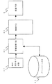
図2は現像手段4によるトナー付着量の制御方法の概略を示す機能ブロック図である。情報源35からの信号を入力として情報取得手段31が取得した用紙の紙種情報は、データベース手段32とリンクして用紙の表面粗さに関する情報を得て、その情報を制御手段30に与え、制御手段30は、現像手段4の印加量を制御する構成となっている。情報源35は、紙種を検知する方法であり、例として、後述するバーコード読み取りや無線IDタグなどがある。
【0046】
画像書きこみのための信号は、ネットワーク等を介して接続されたホストコンピュータから送られてくるものとする。まず、ホストコンピュータが画像形成装置に対して、画像データや指令を含む画像信号を送る。
【0047】
画像形成装置の制御手段30がホストコンピュータからの画像信号を受けると、所定の初期設定動作を経た後で、給紙ローラ12、搬送ローラ13が回転し、給紙カセット10あるいは手差し給紙トレイ16の先端部に用紙Pが引き出され、レジストローラ14により用紙が搬送される。
【0048】
用紙Pが転写部21に至る途中までに、情報取得手段31は紙種に関する情報を取得し、データベース手段32が保有するデータを参照することで、制御手段30に表面粗さに関する情報を送出する。制御手段30は、情報取得手段31から用紙の表面粗さ情報を受け取ると、現像手段4に与える印加量を決定する。
【0049】
また、上記の画像形成条件決定までの動作を行うと同時に、受け取った画像データを書きこみ信号に変換するまでの前処理も行う。現像手段4の印加量が確定すると、一定速度で回転する感光体ドラム1上に帯電手段2で帯電、露光手段3により書きこみ信号に基づいて静電潜像を形成する。現像手段4は制御手段30に与えられた信号により印加量が設定され、現像手段4により感光体ドラム上1の静電潜像が現像されてトナー顕像となる。
【0050】
転写部21において、感光体ドラム1上と転写ローラ5の間にはさみこませて搬送することで、感光体ドラム1上に担持されたトナー像は用紙に転写される。
トナー像を担持した用紙は定着部22に搬送され、加圧ローラおよび加熱ローラによって用紙をはさみ、加熱および加圧を同時に行いながら搬送することで、トナーが溶融すると同時に紙に圧接され、トナー像が用紙上に定着される。定着されたトナー像を担持した用紙は、排紙トレイ18へと送出される。
【0051】
さらに除電手段6により感光体ドラム1表面および感光体ドラム1上に残存するトナーの電荷が除かれ、クリーニング手段7により感光体ドラム1上に残存するトナーが除かれる。
【0052】
以上説明した方法を画像形成に適用することで、用紙の表面粗さに応じて過不足ないトナー量を用紙に付着させることが可能になる。
【0053】
以下、本発明の実施形態である画像形成装置の情報取得手段31が用紙の紙種情報を得る手段を有する場合について説明する。
【0054】
まず、本発明の第1の実施形態について、図1および図6にもとづいて説明する。本実施形態は、可視光のもとでは透明で、紫外線により蛍光を発するインクにより用紙に関する情報を保有したバーコードが印刷されている用紙に適用されるものである。
【0055】
図1において、給紙カセット10と転写部21の間における紙搬送経路の中間に、符号読み取りセンサ20(図示せず)を設け、用紙が符号読み取りセンサ20の下部を通過する際に、用紙上に記録された不可視のバーコードを読み取るように構成したものである。符号読み取りセンサ20は例えば、紫外線発光ダイオードを光源として紙面を照明し、反射光をフォトダイオードで受光するような、バーコード読み取りセンサである。
【0056】
図6は、現像手段4を制御する方法を示した機能ブロック図で、情報源としての符号読み取りセンサ20、制御手段30、データベース手段32、情報取得手段31、および現像手段4から構成されている。符号読み取りセンサ20により、搬送中の転写前の用紙上における不可視のバーコードを読み取り、読み取った信号を情報取得手段31に与えることで紙種に関する情報を取得する。情報取得手段31は紙種に関する情報をもとにデータベース手段32から紙の表面粗さに関する情報を得て、制御手段30に出力する。制御手段30は取得した表面粗さに関する情報をもとに現像手段4の印加量を決定し現像手段4を制御する。
【0057】
透明なバーコードが記録されていない紙については、プリントを中止したり、従来どおりの方法で現像手段4への印加量を決定し制御したりすればよい。
【0058】
以上、本発明の第1の実施形態によれば、用紙自体から紙に関する情報を得ることで、装置本体に備えられた操作パネル等からの紙種指定を行わなくとも、自動的に用紙の表面粗さに応じた付着量の画像を得ることができる。
【0059】
次に、本発明の第2の実施形態について、図1および図7にもとづいて説明する。用紙を所定枚数包装した包装体、または包装体を所定数納めた箱には、文字・記号、バーコード、その他記号で紙種に関する情報が記録されているものとする。
【0060】
原稿を読み取るスキャナを有したプリンタ、または複写機において、図1に示すように、給紙カセットに隣接して給紙カセットセンサ11aが設けられ、給紙カセットが本体に装填されているかどうかを検知する。
【0061】
図7は、現像手段を制御する方法を示した機能ブロック図で、原稿読み取りスキャナ100、制御手段30、前記給紙カセットセンサ11a、画像認識手段33、データベース手段32、情報取得手段31、原稿読み取り開始検知手段34、および現像手段4から構成されている。制御手段30は給紙カセットセンサ11aにより、給紙カセットが本体から引き出されていることを検知し、さらにユーザが読み取り開始を指示したときに、原稿読み取りスキャナで読み取り、画像認識手段32により紙種を特定し、情報取得手段30に出力する。情報取得手段30は取得した紙種に関する情報をもとにデータベース手段32から表面粗さに関する情報を得る。
【0062】
ユーザは用紙を給紙カセットに装填するときに、給紙カセット10を引き出し、原稿読み取りスキャナ100の読み取り面に、装填する用紙の包装体または箱を、載せ、複写開始ボタンを押すことで、紙種に関する情報を読み取らせる。用紙を給紙カセット10に装填後、給紙カセット10を本体に正常に装着することで、読み取った紙種情報をもとに複写またはプリントが行なわれる。
【0063】
以上、本発明の第2の実施形態によれば、複写機については複写機自身のスキャナを使用することで、別途備えつけられたバーコードリーダ等を利用することなく、紙種情報を読み取り、紙種固有の表面粗さにふさわしいトナー量の画像を得ることができる。
【0064】
次に、本発明の第3の実施形態について、図1および図8にもとづいて説明する。用紙を納めた包装紙または箱には、用紙に関する固有情報を保有する無線IDタグが装着されているものとする。また画像形成装置本体内部には、給紙カセット10に隣接して給紙カセットセンサ11aが設けられ、給紙カセット10が本体に装填されているかどうかを検知する。さらに、図示していないが、本体外部の無線IDタグと無線通信する交信手段50をそなえている。
【0065】
図8は、制御手段を制御する方法を示した機能ブロック図で、交信手段50、情報取得手段31、制御手段30、給紙カセットセンサ11a、データベース手段32、現像手段4、および無線IDタグ60から構成されている。無線IDタグ60は普段は非活動状態であるが、交信手段50のアンテナからの特定距離範囲内に接近すると、交信手段50からの特定の電波信号により活動状態に遷移し、交信手段50に対し固有の情報を伝える電波信号を発信するものである。
【0066】
給紙カセット10が本体から引き出されていることを、給紙カセット給紙検知手段11aが検知し、その情報を制御手段30に伝えると、交信手段50が無線IDタグ60と交信を始めるようにする。交信手段50はアンテナによって、無線IDタグ60の存在を検知すると、無線IDタグ60が送信した信号をもとに紙種情報を得て、情報取得手段31に出力する。画像形成時には、情報取得手段31が得た紙種情報をもとに、実施例1で説明した方法と同様の手順で現像手段4を制御する。
【0067】
従って、ユーザが用紙を給紙カセットに装填するときに、無線IDタグ60を有する用紙を納めた包装紙または箱を、所定位置すなわち交信手段50のアンテナ付近に配置し、給紙カセットを引き出すことで、無線タグとの交信を開始し、紙種に関する情報を読み取らせる。用紙を給紙カセットに装填後、給紙カセットを本体に正常に装着することで、読み取った紙種情報をもとに複写またはプリントを行うことができる。
【0068】
以上、本発明の第3の実施形態によれば、ユーザが給紙カセットに用紙補充を行うときの従来の所作とほとんど変わることなく紙種情報を読み取り、紙種固有の表面粗さにふさわしいトナー量の画像を得ることができる。
【0069】
次に、本発明の第4の実施形態について説明する。図11は現像手段によりトナー付着量を制御する方法の概略を示した機能ブロック図である。制御手段30には給紙カセットセンサ11a、手差し給紙センサ11b、表面粗さセンサ19からの信号を入力とし、トナー付着量を制御する信号を出力する構成となっている。画像処理装置内のその他の制御対象については省略している。画像書きこみのための信号は、ネットワーク等を介して接続されたホストコンピュータから送られ制御手段30に与えられるものとする。
【0070】
まず、ホストコンピュータが画像形成装置に対して、画像データや指令を含む画像信号を送る。制御手段30がホストコンピュータからの画像信号を受け取ると、所定の初期設定動作を経た後で、給紙ローラ12、搬送ローラ13が回転し、給紙カセット10あるいは手差し給紙トレイ16の先端部に用紙Pが引き出され、レジストローラ14により搬送される。用紙は転写ローラ5に至る途中で、表面粗さセンサ19により表面粗さを検出して、制御手段30に表面粗さに関する情報を送出する。制御手段30は、表面粗さセンサ19から用紙の表面粗さ情報を受け取ると、前述の図5における対応関係で現像手段4の現像バイアスを決定する。また、表面粗さセンサ19以外の用紙読み取り手段として、紫外線発光ダイオードを光源として紙面を照明し、反射光をフォトダイオードで受光するような、バーコード読み取りセンサである符号読み取りセンサ20(図示せず)も適用可能である。
【0071】
また、上記の画像形成条件決定までの動作を行うと同時に、受け取った画像データを書きこみ信号に変換するまでの前処理も行う。現像手段4の現像バイアスが確定すると、一定速度で回転する感光体ドラム1上に帯電手段2で帯電し、引き続き露光手段3により書きこみ信号に基づいて静電潜像を形成する。現像手段4は、制御手段30により与えられた信号により現像バイアスが設定され、現像手段4により感光体ドラム上1の静電潜像が現像されてトナー顕像となる。その後、用紙への転写と定着を経て、用紙の表面粗さに応じたトナー厚さの画像が得られる。
【0072】
次に、本発明の第5の実施形態であるトナー付着量を制御する方法について説明する。本実施形態は、図11に示すように制御手段30が用紙の表面粗さに応じて現像手段4を制御する代わりに、露光手段3を制御する。
【0073】
帯電させた感光体ドラム1上に露光手段3により潜像を形成する過程において、表面粗さが大きいほど1画素あたりの露光量を大きくすると、トナーに対してより強い静電気力が働くか、または、より領域が拡大した潜像が形成される。その結果、定着後の用紙上のトナー層はより厚くなる。あるいは、露光用レーザービームの光強度を一定とし、走査速度を遅くしても同様の効果が得られる。
【0074】
次に、本発明の第6の実施形態にかかるトナー付着量を制御する方法について図9に基づいて説明する。制御手段30は画像処理手段40を含み、前記画像処理手段40は、情報取得手段31が得た用紙の表面粗さ、および原画像データ52に基づいて中間調画像データ51を生成する。ここで画像処理手段40が原画像データ52を中間調画像データ51に変換する中間調中間調処理において、各階調に対応する網点サイズをより大きくすることで、網点あたりの付着量を増加させることができる。このとき高濃度側で飽和するガンマ特性となる可能性があるが、表面粗さが大きな用紙では定着時にトナーが凸凹を埋めるため、網点がつぶれて径が増大する割合は平滑な用紙の場合より小さくなる。各階調に対応する網点パターンは、ガンマ特性について最適化すればよい。
【0075】
次に、本発明の実施形態である画像形成装置にかかり、用紙の表面粗さを測定する条件あるいは頻度を規定する例について説明する。
【0076】
まず、本発明の第7の実施形態について説明する。用紙の表面粗さRRMS は、例えばプリントジョブ毎に、表面粗さセンサ19により用紙の第1枚目で表面粗さを測定し、同一のプリントジョブ内では同一の条件で画像を形成する。一旦用紙の表面粗さ情報を得ることによって、後続するプリントを継続することができ、 画像形成に適用することで、用紙の表面粗さに応じて適量のトナー量を用紙に付着させることが可能になる。また、表面粗さセンサ19以外の用紙読み取り手段として、紫外線発光ダイオードを光源として紙面を照明し、反射光をフォトダイオードで受光するような、バーコード読み取りセンサである符号読み取りセンサ20(図示せず)も適用可能である。
【0077】
次に、本発明の第8の実施形態について説明する。複数ページから構成される原稿を複数部数プリントする場合において、原稿の同一ページを連続してプリントするソーティング形態においては、原稿のページが変更する毎に表面粗さを測定する。または、2ページ毎、あるいはそれ以上のページ間隔で表面粗さを測定してもよい。
【0078】
原稿を一部毎に連続してプリントするソーティング形態においては、一部毎に最初のページで表面粗さを測定する。または、2部毎、あるいはそれ以上の部数間隔で測定してもよい。また、原稿ページ数とプリント部数の構成にかかわらず、所定枚数毎に測定するようにしてもよい。
【0079】
ここで、表面粗さを測定する頻度は、表面粗さ測定から画像形成条件を決定するまでの時間や画像品質に対する安定性に応じて適宜決めればよく、多数の枚数を連続出力する場合には、出力完了予測時間を推定し、ユーザが望む時間と画像品質に対する優先度に応じて表面粗さを測定する頻度を決定すればよい。
【0080】
次に、本発明の第9の実施形態について説明する。給紙カセット10が引き出されたことを検知、給紙カセット10が正常に本体に収納されていることを検知し、さらに用紙が装填されていることが検知された場合、プリント開始時に、最初の用紙の表面粗さを測定する。それ以降は同一の紙種とみなしてプリントを行う。手差し給紙トレイ16についても同様に上記実施形態が適用できる。さらには、表面粗さを測定する条件は前述の第8の実施形態を適用してもよい。
【0081】
給紙カセット10が引き出された場合には紙種が変更される可能性があるので、少なくとも最初の用紙については用紙の表面粗さを測定することで、紙種変更に対応できる。
【0082】
【発明の効果】
以上のように、本発明の画像形成装置および画像形成方法によれば、アート紙のような平滑な紙に対しては、トナーの付着量を少なくすることで、定着時のドットのつぶれによるドットゲインやそのばらつきが低減され、普通紙のようなラフな紙に対しては、トナーの付着量を多くすることで、紙表面の凹凸を埋めることで場所によるドット形状やドット径のばらつきを低減され、また繊維を被覆することで、繊維表面の反射による明度ムラが低減される。その結果、紙の粗さに依存しない安定な画質の画像を得ることができる。また、平滑な紙に対しては、トナーの付着量を少なくすることで、トナーの使用量を節約することが可能となる。また、紙種を自動認識して、用紙の表面構造に応じたトナー量を用紙上に定着することが可能となり、紙種への依存性が低い安定な画質を得ることが可能になる。
【図面の簡単な説明】
【図1】本発明の実施形態である画像形成装置の概略を示す断面図である。
【図2】本発明の実施形態である画像形成装置の基本機能を示すブロック図である。
【図3】トナー厚さとベタ付着量の関係の一例を示す図である。
【図4】
現像バイアスとベタ付着量の関係の一例を示す図である。
【図5】用紙の表面粗さと現像バイアスの関係の一例を示す図である。
【図6】本発明の第1の実施形態における機能ブロック図である。
【図7】本発明の第2の実施形態における機能ブロック図である。
【図8】本発明の第3の実施形態における機能ブロック図である。
【図9】画像処理手段を含む制御ブロック図である
【図10】用紙の表面粗さの例を示す図である。
【図11】現像手段を制御する場合を例とする制御ブロック図である。
【符号の説明】
1 感光体ドラム
2 帯電手段
3 露光手段
4 現像手段
5 転写ローラ
6 除電手段
7 クリーニング手段
8 加圧ローラ
9 加熱ローラ
10 給紙カセット
11a 給紙カセットセンサ
11b 手差し給紙センサ
12 給紙ローラ
13 搬送ローラ
14 レジストローラ
15 ガイド材
16 手差し給紙トレイ
17 用紙読み取り手段
18 排紙トレイ
19 表面粗さセンサ
20 符号読み取りセンサ
30 制御手段
31 情報取得手段
32 データベース手段
33 画像認識手段
35 情報源
40 画像処理手段
50 交信手段
51 中間調画像データ
52 原画像データ
60 無線IDタグ
100 原稿読み取り手段[0001]
TECHNICAL FIELD OF THE INVENTION
The present invention relates to an electrophotographic image forming apparatus and an image forming method for controlling a toner adhesion amount according to paper roughness.
[0002]
[Prior art]
Printed paper called so-called plain paper is beaten and has a structure in which flat fibers having a height of about 5 μm and a width of about 10 μm intersect in a complicated manner, and have an average roughness of about 5 μm. The mesh portion may have a depression reaching 10 μm to 20 μm in some cases. When the image resolution is 600 dpi, the area within the diameter corresponding to the pixel interval of 42 μm has irregularities of up to 20 μm.
[0003]
An electrophotographic image forming apparatus is characterized in that good image quality can be obtained even with plain paper having fibers by adhering a sufficient amount of toner to fill the irregularities on the paper surface.
[0004]
In recent years, it has become necessary to reduce the amount of toner adhesion from the viewpoint of resource saving and energy saving. However, if the amount of adhered toner is insufficient to fill the irregularities on the surface of the paper, the toner is not sufficiently fixed in the concave portions, and the paper fibers are exposed from the surface of the toner even if the toner is removed. The brightness unevenness occurs due to the fact that it becomes easy to perform. In particular, in the case of paper having a long fiber, it is clear that the possibility that the brightness increases between continuous halftone dots increases, which causes deterioration in graininess and limits the further improvement in image quality.
[0005]
Therefore, in order to obtain an image in which the image quality does not deteriorate even when the toner has a low adhesion amount, a coating liquid is applied to the paper surface to improve smoothness, or a coated paper having no fiber structure on the surface is used. Will be used. In this case, it is necessary to discriminate between plain paper and coated paper, and to change image forming conditions according to the surface characteristics of the paper. In addition, a paper type is selected from an operation panel provided to the image forming apparatus, and an image is output by controlling to output an image corresponding to the paper type. For example, when the user designates a glossy finish, the reflectance of the paper surface is measured by utilizing the characteristic that the specular reflectance of glossy paper is higher than that of plain paper, and the paper is stored in the tray. It is determined whether or not the paper is glossy paper. If the paper is glossy paper, an image is output under the condition of performing gloss finishing. In addition, images can be output according to the type of thick paper, OHP sheet, tracing paper, or the like.
[0006]
As a technology for changing the image forming conditions and outputting an image based on information about the type of paper, the type of paper used in the printer is specified by inputting from the operation panel or by reading the barcode of the wrapping paper. Is acquired from a database, an image is formed under image forming conditions corresponding to the type and characteristics of the paper (for example, surface roughness), and the type of paper (brand, etc.) and its characteristics or corresponding characteristics are obtained. 2. Description of the Related Art There is an image forming apparatus that enables registration in a database by inputting image forming conditions and enables updating of a paper database when paper specifications are changed (for example, see Patent Document 1). There is also an image forming apparatus that stores sheets of paper together with wrapping paper in a paper feed cassette and recognizes a paper type by reading information about the paper recorded on the wrapping paper (for example, see Patent Document 2). In addition, it relates to printing on paper with barcode recorded information about the paper with transparent fluorescent ink visualized by ultraviolet rays. Based on the barcode information recorded on the paper, it matches printing conditions given in advance. There is a printing apparatus that determines whether or not printing has been performed and determines whether or not to perform printing (for example, see Patent Document 3). In addition, as an example of a technique for measuring the surface state of a sheet in an image forming apparatus and changing an image forming condition to output an image, a fixing method using a fixing roller having a hard surface inevitably due to a reason for enhancing thermal conductivity is used. However, due to the problem that thermal conductivity deteriorates due to contact with rough paper, the roughness of the paper is detected by a vibration sensor using a piezoelectric element, and the paper roughness is estimated and fixed based on the measurement information from the vibration sensor. There is an image forming apparatus that changes the temperature (for example, see Patent Document 4). Further, as a similar conventional technique, there is an image forming apparatus that detects glossiness and resistance value of a sheet of paper by a sensor in a sheet transport path and controls transfer separation condition, development condition, and fixing condition based on the detected information. (For example, see Patent Document 5). Further, the paper type is selected on the operation panel provided in the image forming apparatus main body, and the image forming conditions are controlled in accordance with the selection. The characteristics of the paper are surface roughness, the image forming conditions are transfer conditions, the special paper and the like. There is an image forming apparatus that prevents paper jam, transfer failure, and fixing failure in the case of double-sided image output (for example, see Patent Document 6).
[0007]
[Patent Document 1]
JP-A-2002-73291
[Patent Document 2]
JP-A-9-301551
[Patent Document 3]
JP-A-9-30073
[Patent Document 4]
JP-A-2002-340518
[Patent Document 5]
JP-A-8-36329
[Patent Document 6]
JP 2002-202638 A
[0008]
[Problems to be solved by the invention]
However, with the conventional image forming technology that suppresses process condition fluctuations of the image forming apparatus due to the characteristics of the paper and stably obtains image quality regardless of the type of paper, when the amount of toner attached is low, rough paper cannot cover unevenness. Does not take into account the problem of a decline.
[0009]
The present invention has been made in consideration of the above problems, and in order to obtain high quality image when the amount of toner adhesion is small, use a smooth coated paper having no fiber structure, For plain paper having a structure, a sufficient amount of toner is applied to cover the paper fibers. That is, it is an object of the present invention to provide an image forming apparatus and an image forming method which obtain information on the type of paper on which an image is to be formed and control the amount of toner according to the surface structure of the paper type to obtain good image quality. And
[0010]
[Means for Solving the Problems]
In order to achieve the above object, an image forming apparatus according to
[0011]
According to a second aspect of the present invention, there is provided the image forming apparatus according to the first aspect, further comprising an image carrier, and a developing device for visualizing a latent image on the image carrier as a toner image. To the developing means so that the thickness of the toner image fixed to the transfer material becomes an increasing function related to the surface roughness of the transfer material obtained by the information obtaining means within a range of a predetermined minimum value and a predetermined maximum value. It is characterized in that the application amount of is controlled. Therefore, a toner layer having a thickness suitable for the surface roughness of the paper is formed on the paper.
[0012]
According to a third aspect of the present invention, in the image forming apparatus according to the first aspect, the information acquisition unit further includes a sheet reading unit that reads sheet information, and reads information on the transfer material on the transfer material. The information acquisition unit detects the transfer material and acquires the type information of the transfer material. Therefore, the bar code having information on the paper surface structure or the paper previously printed on the paper is read, and the paper type information is directly obtained from the paper itself.
[0013]
According to a fourth aspect of the present invention, in the image forming apparatus according to the third aspect, the sheet reading means is installed in a transfer path of the transfer material before a position where the toner image is transferred onto the surface of the transfer material; Before the toner image is transferred onto the surface of the transfer material, paper information on the transfer material is read. Therefore, the image formation according to the first aspect is performed by obtaining the paper type information from the paper roughness, the bar code on the paper, and the like.
[0014]
An image forming apparatus according to a fifth aspect of the present invention is the image forming apparatus according to the first aspect, further comprising a document reading scanner and a paper feed cassette detecting means, and the information acquisition means is provided by the paper feed cassette detecting means. When it is detected that the paper has been pulled out, the original reading scanner reads the code pattern recorded on the surface of the package containing the predetermined number of transfer materials or the storage box containing the predetermined number of the packages. It is an information acquisition device for acquiring type information of a transfer material. Therefore, when the image forming apparatus is a copying machine, the bar code information is read by the document scanner of the copying machine itself, and information on the paper type is obtained to form an image.
[0015]
According to a sixth aspect of the present invention, there is provided the image forming apparatus according to the first aspect, wherein the communication is performed between a sheet cassette detecting means for detecting that the sheet cassette has been pulled out and a unique information transmitting means. Means, and the information acquisition means, when the paper cassette detection means detects that the paper cassette has been pulled out, a package containing a predetermined number of transfer materials, or a box containing a predetermined number of packages. It is an information acquisition unit that reads a transmission signal from the unique information transmission unit attached to the communication information unit and acquires the type information of the transfer material. Therefore, instead of a bar code, a paper wrapping paper or a storage box with a unique information transmitting means is placed at a predetermined position around a printer or a copying machine, and the information on the paper type is communicated by wireless communication with the unique information transmitting means. Get.
[0016]
In the image forming apparatus according to a seventh aspect, in the image forming apparatus according to the first aspect, the control unit may be configured to control the optical writing so that the larger the surface roughness of the obtained transfer material, the larger the exposure amount. It is characterized by controlling the squeezing means. Therefore, the rougher the surface of the sheet, the more strongly the toner is adsorbed or the larger the latent image is generated, thereby increasing the amount of adhered toner after fixing.
[0017]
According to an eighth aspect of the present invention, in the image forming apparatus of the first aspect, the control unit includes an image processing unit that generates a larger halftone dot as the acquired surface roughness of the transfer material is larger. It is characterized. Therefore, as the surface of the paper becomes rougher, halftone image data having larger halftone dots is generated, thereby increasing the toner adhesion amount after fixing.
[0018]
In the image forming apparatus according to a ninth aspect, in the image forming apparatus according to the first aspect, the control unit is configured to transfer the first and second transfer materials based on information acquired from the first transfer material by the information acquisition unit. It is a control means for controlling image forming conditions on a material. Therefore, by controlling the toner adhesion state based on the information of the first acquired paper, image formation is performed on the succeeding paper.
[0019]
According to a tenth aspect of the present invention, in the image forming apparatus according to the ninth aspect, the information acquiring means acquires information on the surface structure of the transfer material every predetermined number of image forming operations. . Therefore, information is acquired again every predetermined number of sheets, and image formation is performed.
[0020]
An image forming apparatus according to an eleventh aspect of the present invention is the image forming apparatus according to the ninth aspect, further comprising a paper feed detecting unit configured to detect that the paper feeding unit is in a paper possible state, When the first image formation is performed on the transfer material stored in the paper supply unit in the paper supply enabled state based on the information from the paper supply detection unit, information on the surface structure of the transfer material is newly added. Is acquired. Therefore, an image is formed by re-acquiring information each time the sheet feeding cassette or the manual sheet feeding tray is opened.
[0021]
An image forming method according to
[0022]
BEST MODE FOR CARRYING OUT THE INVENTION
Hereinafter, embodiments of the present invention will be described in detail with reference to the accompanying drawings.
[0023]
FIG. 1 is a sectional view schematically showing a main part in an example in which the present invention is applied to an image forming apparatus for forming a monochromatic toner image. In the image forming apparatus shown in FIG. 1, a
[0024]
In the drawing, a
[0025]
A
[0026]
Further, a manual
[0027]
In the paper transport path, above the
[0028]
On the other hand, a
[0029]
Although not shown in FIG. 1, a
[0030]
In the image forming apparatus of the present invention, when the
[0031]
As an index representing the surface roughness of the paper, a value obtained by averaging the standard deviation of the height distribution within a predetermined square area over a sufficiently large area is used. RMS Will be represented by the following symbol. Surface roughness R previously measured for a known paper type RMS May be stored in the database means 32 as a reference table, and the target toner thickness may be determined according to the paper type. The target toner thickness is, for example, within the range of the minimum toner thickness and the maximum toner thickness. RMS May be a function proportional to.
[0032]
Here, the surface roughness sensor 19 (not shown) serving as the
[0033]
Here, the surface roughness R required for the reference table in the database means 32 RMS An example of a method for precisely measuring is described below.
[0034]
The height distribution of the paper within an area of 745 μm × 560 μm was measured using a laser scanning confocal microscope (VK-8500) manufactured by Keyence Corporation, and the measurement area was equally divided into 16 × 12 with a side of 47 μm. For each square area, the standard deviation for the height distribution is determined, averaged, and RMS And FIG. 10 shows the surface roughness R of various papers measured by the method described above. RMS This is an example.
[0035]
The toner adhesion amount for the desired toner thickness is
[Adhesion amount] = [Toner thickness] × [Toner specific gravity]
The relationship is almost satisfied. Surface roughness R when specific gravity = 1.2 in
[0036]
When it is desired to deposit a toner having a thickness of 2 μm on smooth paper and a thickness of 5 μm on coarse paper, when the specific gravity ρ is 1.2 toner, the solid adhesion amount is 0.24 [mg / mg]. cm 2 ], And for solid paper, the solid adhesion amount is 0.6 [mg / cm 2 ]And it is sufficient.
[0037]
The amount of toner adhered is mainly determined by the amount of application in the developing
[0038]
FIG. 4 is a graph showing an example of the relationship between the amounts of toner adhered when a solid image is fixed on a sheet by changing the developing bias in an experimental machine of an electrophotographic image forming apparatus.
[0039]
FIG. 5 shows that the toner thickness when a solid image is output is, for example, R RMS In the case where the lower limit of the developing bias is set to 350 V and the upper limit is set to 550 V by using the image forming apparatus having the developing characteristics shown in FIG. Surface roughness R received by the
[0040]
The control means 30 controls the surface roughness R shown in FIG. RMS And the conversion means equivalent to the relationship between the developing bias applied to the developing
[0041]
Depending on the accuracy of the surface roughness measured by the method described above, the measured surface roughness may be divided into ranks to determine the applied developing bias. For example, from the graph of the relationship between the surface roughness and the applied developing bias shown in FIG. 5, the relationship between the surface roughness and the developing bias is shown in Table 1 below.
[0042]
[Table 1]
The surface roughness data of each paper type shown in FIG. 10 corresponds to a developing bias of 350 V for the coated paper of the paper types A to D and a developing bias of 450 V for the plain paper of the paper types E to J. It suffices that at least the surface roughness can be measured with an accuracy such that coated paper and plain paper can be distinguished, that is, two ranks.
[0044]
An image forming operation when the image forming apparatus according to the present embodiment configured as described above is operated as a printer will be described with reference to FIGS.
[0045]
FIG. 2 is a functional block diagram schematically showing a method of controlling the amount of toner adhered by the developing
[0046]
A signal for writing an image is transmitted from a host computer connected via a network or the like. First, the host computer sends an image signal including image data and a command to the image forming apparatus.
[0047]
When the control means 30 of the image forming apparatus receives an image signal from the host computer, after a predetermined initializing operation, the
[0048]
By the time the sheet P reaches the
[0049]
In addition, at the same time as performing the above-described operations up to the determination of the image forming conditions, pre-processing until the received image data is converted into a write signal is also performed. When the applied amount of the developing
[0050]
In the
The sheet carrying the toner image is conveyed to the fixing
[0051]
Further, the charge of the toner remaining on the surface of the
[0052]
By applying the method described above to image formation, it is possible to cause a sufficient amount of toner to adhere to a sheet according to the surface roughness of the sheet.
[0053]
Hereinafter, a case will be described in which the information acquisition unit 31 of the image forming apparatus according to the embodiment of the present invention has a unit for acquiring sheet type information of a sheet.
[0054]
First, a first embodiment of the present invention will be described with reference to FIGS. The present embodiment is applied to a sheet on which a barcode having information on the sheet is printed using ink which is transparent under visible light and emits fluorescence by ultraviolet rays.
[0055]
In FIG. 1, a code reading sensor 20 (not shown) is provided in the middle of a paper conveyance path between the
[0056]
FIG. 6 is a functional block diagram showing a method of controlling the developing
[0057]
For paper on which a transparent barcode is not recorded, printing may be stopped, or the amount applied to the developing
[0058]
As described above, according to the first embodiment of the present invention, the information on the paper is obtained from the paper itself, so that the front side of the paper is automatically specified without specifying the paper type from an operation panel or the like provided in the apparatus main body. It is possible to obtain an image having an attached amount according to the roughness.
[0059]
Next, a second embodiment of the present invention will be described with reference to FIGS. A package in which a predetermined number of sheets of paper are packed, or a box in which a predetermined number of packages are stored, is assumed to have information about the paper type recorded in characters, symbols, bar codes, and other symbols.
[0060]
As shown in FIG. 1, in a printer or a copier having a scanner for reading an original, a
[0061]
FIG. 7 is a functional block diagram showing a method for controlling the developing means. The
[0062]
When the user loads paper into the paper feed cassette, the user pulls out the
[0063]
As described above, according to the second embodiment of the present invention, the paper type information is read by using the scanner of the copying machine itself without using a barcode reader or the like separately provided, and the paper type is read. It is possible to obtain an image with a toner amount appropriate for the surface roughness inherent to the species.
[0064]
Next, a third embodiment of the present invention will be described with reference to FIGS. It is assumed that a wrapping paper or a box containing the paper is provided with a wireless ID tag holding unique information on the paper. Further, inside the image forming apparatus main body, a paper
[0065]
FIG. 8 is a functional block diagram showing a method of controlling the control means. The communication means 50, the information acquisition means 31, the control means 30, the
[0066]
When the feed cassette
[0067]
Therefore, when the user loads paper into the paper feed cassette, the user places the wrapping paper or box containing the paper having the wireless ID tag 60 at a predetermined position, that is, near the antenna of the communication means 50, and pulls out the paper feed cassette. Then, communication with the wireless tag is started, and information on the paper type is read. After the paper is loaded in the paper cassette, the paper cassette is normally mounted on the main body, so that copying or printing can be performed based on the read paper type information.
[0068]
As described above, according to the third embodiment of the present invention, the paper type information is read almost in the same manner as the conventional operation when the user replenishes the paper in the paper feed cassette, and the toner suitable for the surface roughness inherent to the paper type is read. A quantity of images can be obtained.
[0069]
Next, a fourth embodiment of the present invention will be described. FIG. 11 is a functional block diagram schematically showing a method for controlling the amount of toner adhesion by the developing means. The
[0070]
First, the host computer sends an image signal including image data and a command to the image forming apparatus. When the control means 30 receives the image signal from the host computer, after a predetermined initial setting operation, the
[0071]
In addition, at the same time as performing the above-described operations up to the determination of the image forming conditions, pre-processing until the received image data is converted into a write signal is also performed. When the developing bias of the developing
[0072]
Next, a method of controlling a toner adhesion amount according to a fifth embodiment of the present invention will be described. In the present embodiment, as shown in FIG. 11, the
[0073]
In the process of forming a latent image on the charged
[0074]
Next, a method for controlling the toner adhesion amount according to a sixth embodiment of the present invention will be described with reference to FIG. The
[0075]
Next, an example will be described in which the image forming apparatus according to the embodiment of the present invention defines conditions or frequencies for measuring the surface roughness of a sheet.
[0076]
First, a seventh embodiment of the present invention will be described. Paper surface roughness R RMS For example, for each print job, the surface roughness of the first sheet of paper is measured by the
[0077]
Next, an eighth embodiment of the present invention will be described. In the case of printing a plurality of copies of a document composed of a plurality of pages, in a sorting mode in which the same pages of the document are continuously printed, the surface roughness is measured every time the pages of the document are changed. Alternatively, the surface roughness may be measured every two pages or at intervals of two or more pages.
[0078]
In a sorting mode in which a document is continuously printed every part, the surface roughness is measured on the first page for every part. Alternatively, it may be measured every two copies or at intervals of more copies. Also, the measurement may be performed for each predetermined number of sheets regardless of the configuration of the number of original pages and the number of print copies.
[0079]
Here, the frequency of measuring the surface roughness may be appropriately determined according to the time from the surface roughness measurement to the determination of the image forming conditions and the stability to the image quality, and in the case of continuously outputting a large number of sheets, The estimated output completion time may be estimated, and the frequency of measuring the surface roughness may be determined according to the time desired by the user and the priority for the image quality.
[0080]
Next, a ninth embodiment of the present invention will be described. If it is detected that the
[0081]
When the
[0082]
【The invention's effect】
As described above, according to the image forming apparatus and the image forming method of the present invention, for smooth paper such as art paper, by reducing the amount of toner adherence, the dot due to dot collapse at the time of fixing is reduced. The gain and its variation are reduced, and for rough paper such as plain paper, the amount of toner attached is increased to fill in irregularities on the paper surface, thereby reducing dot shape and dot diameter variations due to locations. In addition, by coating the fiber, unevenness in brightness due to reflection on the fiber surface is reduced. As a result, it is possible to obtain an image of stable image quality that does not depend on the paper roughness. Further, it is possible to reduce the amount of toner used on smooth paper by reducing the amount of toner attached. Further, the paper type can be automatically recognized, and the amount of toner corresponding to the surface structure of the paper can be fixed on the paper, so that a stable image quality with little dependence on the paper type can be obtained.
[Brief description of the drawings]
FIG. 1 is a sectional view schematically showing an image forming apparatus according to an embodiment of the present invention.
FIG. 2 is a block diagram illustrating basic functions of the image forming apparatus according to the exemplary embodiment of the present invention.
FIG. 3 is a diagram illustrating an example of a relationship between a toner thickness and a solid adhesion amount.
FIG. 4
FIG. 6 is a diagram illustrating an example of a relationship between a developing bias and a solid adhesion amount.
FIG. 5 is a diagram illustrating an example of a relationship between a surface roughness of a sheet and a developing bias.
FIG. 6 is a functional block diagram according to the first embodiment of the present invention.
FIG. 7 is a functional block diagram according to a second embodiment of the present invention.
FIG. 8 is a functional block diagram according to a third embodiment of the present invention.
FIG. 9 is a control block diagram including an image processing unit.
FIG. 10 is a diagram illustrating an example of the surface roughness of a sheet.
FIG. 11 is a control block diagram illustrating an example of controlling a developing unit.
[Explanation of symbols]
1 Photoconductor drum
2 Charging means
3 Exposure means
4 Developing means
5 Transfer roller
6 Static elimination means
7 Cleaning means
8 Pressure roller
9 Heating roller
10 Paper cassette
11a Paper cassette sensor
11b Manual feed sensor
12 Paper feed roller
13 Transport rollers
14 Registration roller
15 Guide material
16 Manual paper feed tray
17 Paper reading means
18 Output tray
19 Surface roughness sensor
20 Code reading sensor
30 control means
31 Information acquisition means
32 Database means
33 Image Recognition Means
35 information sources
40 Image processing means
50 Communication means
51 Halftone image data
52 Original image data
60 Wireless ID tag
100 Document reading means
Claims (12)
前記像担持体および前記像担持体上の前記潜像をトナー像として顕像化する現像手段と、
前記像担持体上の前記トナー像を転写材上に密着させることで転写する転写手段と、
前記転写材上に形成された前記トナー像を前記転写材に定着することで可視像を固定する定着手段と、
前記転写材の表面構造に関する情報を取得する情報取得手段と、
前記情報取得手段によって取得された情報に基づき、画像形成条件を制御する制御手段と、
前記転写材の種類に関する情報を取得する転写材種別取得手段と、
前記転写材の種別に対応した表面粗さに関するデータを蓄積したデータベース手段とを有し、
前記情報取得手段が取得する情報は前記転写材の表面粗さであり、前記制御手段は前記表面粗さが大きいほどトナー付着量が増加するように制御を行うことを特徴とする画像形成装置。Exposure means for forming a latent image on a charged image carrier based on halftone image data,
Developing means for developing the latent image on the image carrier and the image carrier as a toner image,
Transfer means for transferring the toner image on the image carrier by bringing the toner image into close contact with a transfer material,
Fixing means for fixing a visible image by fixing the toner image formed on the transfer material to the transfer material,
Information acquisition means for acquiring information about the surface structure of the transfer material,
Control means for controlling image forming conditions based on the information obtained by the information obtaining means,
Transfer material type obtaining means for obtaining information on the type of the transfer material,
Database means for storing data relating to the surface roughness corresponding to the type of the transfer material,
The information obtained by the information obtaining means is the surface roughness of the transfer material, and the control means performs control so that the larger the surface roughness, the larger the amount of toner adhesion.
前記転写材上に記録された転写材に関する情報を、前記用紙読み取り手段によって検出し、前記転写材の種別情報を取得することを特徴とする請求項1記載の画像形成装置。The information acquisition unit further includes a sheet reading unit that reads sheet information,
The image forming apparatus according to claim 1, wherein information about the transfer material recorded on the transfer material is detected by the paper reading unit, and the type information of the transfer material is acquired.
前記転写材の表面に前記トナー像が転写される以前に、前記転写材上の用紙情報を読み取ることを特徴とする請求項3記載の画像形成装置。The paper reading unit is installed in a transfer path of the transfer material before a position where the toner image is transferred to a surface of the transfer material,
4. The image forming apparatus according to claim 3, wherein paper information on the transfer material is read before the toner image is transferred onto the surface of the transfer material.
前記情報取得手段は、前記給紙カセット検知手段によって前記給紙カセットが引き出されたことを検知した時に、前記原稿読み取り用スキャナにより前記転写材を所定枚数納めた包装体、または包装体を所定入り数納めた収納箱の表面に記録された符号パターンを読み取ることで前記転写材の種別情報を取得することを特徴とする請求項3記載の画像形成装置。An original reading scanner, and a paper feed cassette detecting means for detecting that the paper feed cassette has been pulled out,
The information obtaining means, when the paper feed cassette detecting means detects that the paper feed cassette has been pulled out, inserts a predetermined number of packages containing the transfer material by the original reading scanner, or a predetermined number of packages. 4. The image forming apparatus according to claim 3, wherein the type information of the transfer material is acquired by reading a code pattern recorded on a surface of the storage box in which the storage material is stored.
固有情報発信手段との間で交信する交信手段とをさらに有し、
前記情報取得手段は、前記給紙カセット検知手段によって前記給紙カセットが引き出されたことを検知した時に、前記転写材を所定枚数納めた包装体、または包装体を所定入り数納めた箱に貼付された前記固有情報発信手段からの送信信号を前記交信手段により読み取り、前記転写材の種別情報を取得することを特徴とする請求項1記載の画像形成装置。Paper cassette detecting means for detecting that the paper cassette has been pulled out,
Communication means for communicating with the unique information transmission means,
The information acquisition unit, when detecting that the paper cassette has been pulled out by the paper cassette detection unit, affixes the package containing a predetermined number of the transfer materials or a box containing a predetermined number of the packages. 2. The image forming apparatus according to claim 1, wherein the communication unit reads the transmitted transmission signal from the unique information transmission unit and acquires the type information of the transfer material.
前記情報取得手段は、前記給紙検知手段からの情報に基づいて、給紙可能状態とされた前記給紙手段に格納された転写材に対して最初に画像形成を行う際には前記転写材の表面構造に関する情報を新たに取得することを特徴とする請求項9記載の画像形成装置。Further comprising paper feed detecting means for detecting that the paper feed means is in a paper ready state,
The information acquisition unit is configured to perform the image formation on the transfer material stored in the sheet supply unit in the sheet supply enabled state for the first time based on the information from the sheet supply detection unit. The image forming apparatus according to claim 9, wherein information regarding a surface structure of the image forming apparatus is newly acquired.
前記像担持体および前記像担持体上の前記潜像をトナー像として顕像化する現像ステップと、
前記像担持体上の前記トナー像を転写材上に密着させることで転写する転写ステップと、
前記転写材上に形成された前記トナー像を前記転写材に定着することで可視像を固定する定着ステップと、
前記転写材の表面構造に関する情報を取得する情報取得ステップと、
前記情報取得ステップによって取得された情報に基づき、画像形成条件を制御する制御ステップと、
前記転写材の種類に関する情報を取得する転写材種別取得ステップと、
前記転写材の種別に対応した表面粗さに関するデータを蓄積したデータベースステップとを有し、
前記情報取得ステップが取得する情報は前記転写材の表面粗さであり、前記制御ステップは前記表面粗さが大きいほどトナー付着量が増加するように制御を行うことを特徴とする画像形成方法。An exposure step of forming a latent image on the charged image carrier based on the halftone image data;
A developing step of visualizing the latent image on the image carrier and the image carrier as a toner image,
A transfer step of transferring the toner image on the image carrier by bringing the toner image into close contact with a transfer material,
A fixing step of fixing a visible image by fixing the toner image formed on the transfer material to the transfer material,
Information acquisition step of acquiring information about the surface structure of the transfer material,
A control step of controlling image forming conditions based on the information obtained by the information obtaining step,
A transfer material type obtaining step of obtaining information on the type of the transfer material,
A database step of storing data on surface roughness corresponding to the type of the transfer material,
The information obtained by the information obtaining step is a surface roughness of the transfer material, and the control step performs control so that the toner adhesion amount increases as the surface roughness increases.
Priority Applications (1)
| Application Number | Priority Date | Filing Date | Title |
|---|---|---|---|
| JP2003049810A JP2004258397A (en) | 2003-02-26 | 2003-02-26 | Apparatus and method for image formation |
Applications Claiming Priority (1)
| Application Number | Priority Date | Filing Date | Title |
|---|---|---|---|
| JP2003049810A JP2004258397A (en) | 2003-02-26 | 2003-02-26 | Apparatus and method for image formation |
Publications (1)
| Publication Number | Publication Date |
|---|---|
| JP2004258397A true JP2004258397A (en) | 2004-09-16 |
Family
ID=33115422
Family Applications (1)
| Application Number | Title | Priority Date | Filing Date |
|---|---|---|---|
| JP2003049810A Withdrawn JP2004258397A (en) | 2003-02-26 | 2003-02-26 | Apparatus and method for image formation |
Country Status (1)
| Country | Link |
|---|---|
| JP (1) | JP2004258397A (en) |
Cited By (19)
| Publication number | Priority date | Publication date | Assignee | Title |
|---|---|---|---|---|
| JP2006091349A (en) * | 2004-09-22 | 2006-04-06 | Fuji Xerox Co Ltd | Image forming apparatus and image forming system |
| JP2006259031A (en) * | 2005-03-16 | 2006-09-28 | Ricoh Co Ltd | Process cartridge, image forming apparatus, and image forming method |
| JP2006293161A (en) * | 2005-04-13 | 2006-10-26 | Sharp Corp | Image forming apparatus and its control program |
| JP2007033494A (en) * | 2005-07-22 | 2007-02-08 | Konica Minolta Business Technologies Inc | Image forming apparatus |
| JP2007286182A (en) * | 2006-04-13 | 2007-11-01 | Canon Inc | Method for measuring recording material amount, image forming method, device for measuring recording material amount and image forming apparatus |
| JP2008083595A (en) * | 2006-09-28 | 2008-04-10 | Sharp Corp | Image forming apparatus |
| JP2009139561A (en) * | 2007-12-05 | 2009-06-25 | Fuji Xerox Co Ltd | Image forming apparatus |
| US7903987B2 (en) | 2008-05-09 | 2011-03-08 | Ricoh Company Limited | Image forming apparatus and control method therefor |
| WO2011096085A1 (en) * | 2010-02-08 | 2011-08-11 | キヤノン株式会社 | Image formation device |
| US8059981B2 (en) | 2008-06-26 | 2011-11-15 | Ricoh Company Limited | Image forming apparatus and control method therefor |
| EP2500782A2 (en) | 2011-03-18 | 2012-09-19 | Ricoh Company, Ltd. | Image forming apparatus and image forming method |
| JP2012194445A (en) * | 2011-03-17 | 2012-10-11 | Ricoh Co Ltd | Optical sensor and image forming apparatus |
| US8599438B2 (en) | 2009-01-30 | 2013-12-03 | Konica Minolta Business Technologies, Inc. | Image forming apparatus |
| US8923716B2 (en) | 2010-08-18 | 2014-12-30 | Ricoh Company, Limited | Transfer device, image forming apparatus, and transfer method |
| JP2015003402A (en) * | 2013-06-19 | 2015-01-08 | 富士フイルム株式会社 | Image forming apparatus and image forming method |
| EP2405305A3 (en) * | 2007-09-28 | 2015-07-01 | Oki Data Corporation | Image forming apparatus |
| US9176438B2 (en) | 2013-03-15 | 2015-11-03 | Ricoh Company, Ltd. | Image forming apparatus and method of arranging sheet detector |
| JP2020073338A (en) * | 2020-01-28 | 2020-05-14 | キヤノン株式会社 | Printing device, printing device control method and program |
| US10948840B2 (en) | 2018-11-27 | 2021-03-16 | Oki Data Corporation | Toner container, image forming unit, and image forming apparatus |
-
2003
- 2003-02-26 JP JP2003049810A patent/JP2004258397A/en not_active Withdrawn
Cited By (24)
| Publication number | Priority date | Publication date | Assignee | Title |
|---|---|---|---|---|
| JP2006091349A (en) * | 2004-09-22 | 2006-04-06 | Fuji Xerox Co Ltd | Image forming apparatus and image forming system |
| JP2006259031A (en) * | 2005-03-16 | 2006-09-28 | Ricoh Co Ltd | Process cartridge, image forming apparatus, and image forming method |
| JP2006293161A (en) * | 2005-04-13 | 2006-10-26 | Sharp Corp | Image forming apparatus and its control program |
| JP2007033494A (en) * | 2005-07-22 | 2007-02-08 | Konica Minolta Business Technologies Inc | Image forming apparatus |
| JP2007286182A (en) * | 2006-04-13 | 2007-11-01 | Canon Inc | Method for measuring recording material amount, image forming method, device for measuring recording material amount and image forming apparatus |
| JP2008083595A (en) * | 2006-09-28 | 2008-04-10 | Sharp Corp | Image forming apparatus |
| EP2405305A3 (en) * | 2007-09-28 | 2015-07-01 | Oki Data Corporation | Image forming apparatus |
| JP2009139561A (en) * | 2007-12-05 | 2009-06-25 | Fuji Xerox Co Ltd | Image forming apparatus |
| US7903987B2 (en) | 2008-05-09 | 2011-03-08 | Ricoh Company Limited | Image forming apparatus and control method therefor |
| US8059981B2 (en) | 2008-06-26 | 2011-11-15 | Ricoh Company Limited | Image forming apparatus and control method therefor |
| US8599438B2 (en) | 2009-01-30 | 2013-12-03 | Konica Minolta Business Technologies, Inc. | Image forming apparatus |
| US8199181B2 (en) | 2010-02-08 | 2012-06-12 | Canon Kabushiki Kaisha | Image forming apparatus |
| WO2011096085A1 (en) * | 2010-02-08 | 2011-08-11 | キヤノン株式会社 | Image formation device |
| JP5430681B2 (en) * | 2010-02-08 | 2014-03-05 | キヤノン株式会社 | Image forming apparatus |
| US8923716B2 (en) | 2010-08-18 | 2014-12-30 | Ricoh Company, Limited | Transfer device, image forming apparatus, and transfer method |
| JP2012194445A (en) * | 2011-03-17 | 2012-10-11 | Ricoh Co Ltd | Optical sensor and image forming apparatus |
| US8712267B2 (en) | 2011-03-18 | 2014-04-29 | Ricoh Company, Ltd. | Image forming apparatus and image forming method |
| EP2500782A2 (en) | 2011-03-18 | 2012-09-19 | Ricoh Company, Ltd. | Image forming apparatus and image forming method |
| US9285723B2 (en) | 2011-03-18 | 2016-03-15 | Ricoh Company, Ltd. | Image forming apparatus and image forming method |
| US9176438B2 (en) | 2013-03-15 | 2015-11-03 | Ricoh Company, Ltd. | Image forming apparatus and method of arranging sheet detector |
| JP2015003402A (en) * | 2013-06-19 | 2015-01-08 | 富士フイルム株式会社 | Image forming apparatus and image forming method |
| US10948840B2 (en) | 2018-11-27 | 2021-03-16 | Oki Data Corporation | Toner container, image forming unit, and image forming apparatus |
| US11256189B2 (en) | 2018-11-27 | 2022-02-22 | Oki Electric Industry Co., Ltd. | Toner container, image forming unit, and image forming apparatus |
| JP2020073338A (en) * | 2020-01-28 | 2020-05-14 | キヤノン株式会社 | Printing device, printing device control method and program |
Similar Documents
| Publication | Publication Date | Title |
|---|---|---|
| JP2004258397A (en) | Apparatus and method for image formation | |
| JP5303265B2 (en) | Image forming apparatus and image forming method | |
| JP4781191B2 (en) | Image forming apparatus and image forming method | |
| US7283762B2 (en) | Glossing system for use in a printing architecture | |
| US7412180B2 (en) | Glossing system for use in a printing system | |
| JP4671824B2 (en) | Image forming apparatus | |
| CN1892468B (en) | Paper detection apparatus and printing method | |
| US7382992B2 (en) | Sheet material identification apparatus and image forming apparatus therewith | |
| US6856430B1 (en) | Calculation of toner usage | |
| US20090324259A1 (en) | Condition determining system, method of detecting abnormality of condition determining system, and image forming apparatus | |
| US8582179B2 (en) | Image forming apparatus and image forming system for adjusting a density of a formed image based on measured densities of a prescribed test image | |
| US20110008086A1 (en) | Image forming apparatus, clear layer forming apparatus, and image forming system | |
| US7184180B2 (en) | Image forming apparatus, image forming method and program, and recording medium | |
| KR20100030047A (en) | Image forming apparatus and method for cleaning contaminated portions of the image forming apparatus | |
| JP2013029871A (en) | Image forming apparatus and image forming method | |
| JP2004323197A (en) | Image formation device | |
| JP2005208105A (en) | Image forming apparatus and image forming method therefor | |
| US9612560B2 (en) | Printing system method and apparatus for comparing calculated sheets needed against sheets available | |
| KR101563014B1 (en) | Method and apparatus for automatically adjusting nip width based on a scanned nip print image on ultraviolet-sensitive media in an image production device | |
| JP2006126281A (en) | Image forming apparatus | |
| JP2977462B2 (en) | Image forming device | |
| JP2002003014A (en) | Image forming device | |
| JP7534903B2 (en) | Image forming device | |
| US20040001722A1 (en) | Apparatus and method of providing replacement instructions for consumable items used in an image forming apparatus | |
| US7903991B2 (en) | Method and apparatus for measuring nip width in an image production device |
Legal Events
| Date | Code | Title | Description |
|---|---|---|---|
| A300 | Withdrawal of application because of no request for examination |
Free format text: JAPANESE INTERMEDIATE CODE: A300 Effective date: 20060509 |