JP2004254285A - Receiver, transmitter and receiving method - Google Patents
Receiver, transmitter and receiving method Download PDFInfo
- Publication number
- JP2004254285A JP2004254285A JP2003366249A JP2003366249A JP2004254285A JP 2004254285 A JP2004254285 A JP 2004254285A JP 2003366249 A JP2003366249 A JP 2003366249A JP 2003366249 A JP2003366249 A JP 2003366249A JP 2004254285 A JP2004254285 A JP 2004254285A
- Authority
- JP
- Japan
- Prior art keywords
- signal
- reception
- antenna
- channel
- unit
- Prior art date
- Legal status (The legal status is an assumption and is not a legal conclusion. Google has not performed a legal analysis and makes no representation as to the accuracy of the status listed.)
- Granted
Links
- 238000000034 method Methods 0.000 title claims description 96
- 230000005540 biological transmission Effects 0.000 claims abstract description 346
- 238000012545 processing Methods 0.000 claims abstract description 181
- 239000011159 matrix material Substances 0.000 claims abstract description 176
- 238000004891 communication Methods 0.000 claims abstract description 55
- 238000004364 calculation method Methods 0.000 claims description 120
- 230000005684 electric field Effects 0.000 claims description 47
- 230000015572 biosynthetic process Effects 0.000 claims description 22
- 238000003786 synthesis reaction Methods 0.000 claims description 22
- 238000001514 detection method Methods 0.000 claims description 9
- 238000000926 separation method Methods 0.000 abstract description 35
- 238000012937 correction Methods 0.000 description 114
- 238000010586 diagram Methods 0.000 description 39
- 230000007480 spreading Effects 0.000 description 35
- 238000006243 chemical reaction Methods 0.000 description 25
- 230000008569 process Effects 0.000 description 23
- 239000000969 carrier Substances 0.000 description 12
- 238000007476 Maximum Likelihood Methods 0.000 description 8
- 230000008859 change Effects 0.000 description 7
- 238000005562 fading Methods 0.000 description 4
- 238000001228 spectrum Methods 0.000 description 4
- 238000001308 synthesis method Methods 0.000 description 4
- 230000002194 synthesizing effect Effects 0.000 description 4
- 238000009792 diffusion process Methods 0.000 description 3
- 230000000694 effects Effects 0.000 description 3
- 230000007274 generation of a signal involved in cell-cell signaling Effects 0.000 description 3
- 238000010187 selection method Methods 0.000 description 3
- 238000004088 simulation Methods 0.000 description 3
- 238000013461 design Methods 0.000 description 2
- 239000000203 mixture Substances 0.000 description 2
- 230000003044 adaptive effect Effects 0.000 description 1
- 230000003321 amplification Effects 0.000 description 1
- 230000008901 benefit Effects 0.000 description 1
- 239000002131 composite material Substances 0.000 description 1
- 230000007423 decrease Effects 0.000 description 1
- 238000005516 engineering process Methods 0.000 description 1
- 230000006872 improvement Effects 0.000 description 1
- 238000003199 nucleic acid amplification method Methods 0.000 description 1
- 230000010363 phase shift Effects 0.000 description 1
- 238000012827 research and development Methods 0.000 description 1
- 230000003595 spectral effect Effects 0.000 description 1
- 230000009466 transformation Effects 0.000 description 1
Images


Classifications
-
- H—ELECTRICITY
- H04—ELECTRIC COMMUNICATION TECHNIQUE
- H04B—TRANSMISSION
- H04B7/00—Radio transmission systems, i.e. using radiation field
- H04B7/02—Diversity systems; Multi-antenna system, i.e. transmission or reception using multiple antennas
- H04B7/04—Diversity systems; Multi-antenna system, i.e. transmission or reception using multiple antennas using two or more spaced independent antennas
- H04B7/0413—MIMO systems
- H04B7/0426—Power distribution
- H04B7/043—Power distribution using best eigenmode, e.g. beam forming or beam steering
-
- H—ELECTRICITY
- H04—ELECTRIC COMMUNICATION TECHNIQUE
- H04B—TRANSMISSION
- H04B17/00—Monitoring; Testing
- H04B17/30—Monitoring; Testing of propagation channels
- H04B17/309—Measuring or estimating channel quality parameters
- H04B17/318—Received signal strength
-
- H—ELECTRICITY
- H04—ELECTRIC COMMUNICATION TECHNIQUE
- H04B—TRANSMISSION
- H04B7/00—Radio transmission systems, i.e. using radiation field
- H04B7/02—Diversity systems; Multi-antenna system, i.e. transmission or reception using multiple antennas
- H04B7/04—Diversity systems; Multi-antenna system, i.e. transmission or reception using multiple antennas using two or more spaced independent antennas
- H04B7/06—Diversity systems; Multi-antenna system, i.e. transmission or reception using multiple antennas using two or more spaced independent antennas at the transmitting station
- H04B7/0613—Diversity systems; Multi-antenna system, i.e. transmission or reception using multiple antennas using two or more spaced independent antennas at the transmitting station using simultaneous transmission
- H04B7/0615—Diversity systems; Multi-antenna system, i.e. transmission or reception using multiple antennas using two or more spaced independent antennas at the transmitting station using simultaneous transmission of weighted versions of same signal
- H04B7/0619—Diversity systems; Multi-antenna system, i.e. transmission or reception using multiple antennas using two or more spaced independent antennas at the transmitting station using simultaneous transmission of weighted versions of same signal using feedback from receiving side
- H04B7/0621—Feedback content
-
- H—ELECTRICITY
- H04—ELECTRIC COMMUNICATION TECHNIQUE
- H04B—TRANSMISSION
- H04B17/00—Monitoring; Testing
- H04B17/20—Monitoring; Testing of receivers
- H04B17/24—Monitoring; Testing of receivers with feedback of measurements to the transmitter
-
- H—ELECTRICITY
- H04—ELECTRIC COMMUNICATION TECHNIQUE
- H04B—TRANSMISSION
- H04B7/00—Radio transmission systems, i.e. using radiation field
- H04B7/02—Diversity systems; Multi-antenna system, i.e. transmission or reception using multiple antennas
- H04B7/04—Diversity systems; Multi-antenna system, i.e. transmission or reception using multiple antennas using two or more spaced independent antennas
- H04B7/08—Diversity systems; Multi-antenna system, i.e. transmission or reception using multiple antennas using two or more spaced independent antennas at the receiving station
- H04B7/0837—Diversity systems; Multi-antenna system, i.e. transmission or reception using multiple antennas using two or more spaced independent antennas at the receiving station using pre-detection combining
- H04B7/0842—Weighted combining
- H04B7/0848—Joint weighting
-
- H—ELECTRICITY
- H04—ELECTRIC COMMUNICATION TECHNIQUE
- H04W—WIRELESS COMMUNICATION NETWORKS
- H04W52/00—Power management, e.g. TPC [Transmission Power Control], power saving or power classes
- H04W52/04—TPC
- H04W52/38—TPC being performed in particular situations
- H04W52/42—TPC being performed in particular situations in systems with time, space, frequency or polarisation diversity
Abstract
Description
本発明は受信装置、送信装置及び受信方法に関し、特にマルチアンテナを用いた無線通信システムに適用される受信装置、送信装置及び受信方法に関するものである。 The present invention relates to a receiving apparatus, a transmitting apparatus, and a receiving method, and more particularly to a receiving apparatus, a transmitting apparatus, and a receiving method that are applied to a wireless communication system using a multi-antenna.
従来、限られた周波数帯域でより多くのデータの送受信を可能とするためにマルチアンテナを用いた無線通信システムの研究・開発が盛んに行われている。マルチアンテナを用いた無線通信システムの例としては、送信装置と受信装置の双方に複数アンテナを設けたMIMO(Multiple-Input Multiple-Output)システムや、送信装置に複数アンテナを設け受信装置に1つのアンテナを設けたMISO(Multiple-Input Single-Output)システムがある。このうちMISOシステムにおける受信品質を向上させる技術として、例えば特許文献1に開示された発明が知られている。
2. Description of the Related Art Conventionally, research and development of a wireless communication system using a multi-antenna has been actively performed in order to enable transmission / reception of more data in a limited frequency band. Examples of a wireless communication system using a multi-antenna include a MIMO (Multiple-Input Multiple-Output) system in which a plurality of antennas are provided in both a transmission device and a reception device, and a reception device in which a plurality of antennas are provided in the transmission device. There is a MISO (Multiple-Input Single-Output) system provided with an antenna. Among these, as a technique for improving the reception quality in the MISO system, for example, the invention disclosed in
図50に、MISOシステムの原理的な構成を示す。変調信号生成部3はディジタル信号1、2を入力とし、これらを変調して変調信号4、5を出力する。無線部6は変調信号4、5を入力とし、ディジタルアナログ変換や無線周波数変換等の無線処理を行うことで送信信号7、8を得る。送信信号7、8はそれぞれアンテナ9、10から電波として送信される。無線部13は、アンテナ11で受信した受信信号12を入力とし、ダウンコンバートやアナログディジタル変換等の無線処理を行うことでベースバンド信号14を得る。ここでベースバンド信号14は伝搬路上で変調信号4、5が多重された状態の信号であるため、復調部15はベースバンド信号14を各信号に対して分離処理を含む復調処理を施して受信ディジタル信号16を得る。
ところで、このようにマルチアンテナ技術を用いた無線通信システムでは、複数のアンテナから送信した変調信号が伝搬路上で多重されて受信側のアンテナで受信されるため、信号分離処理を含む復調処理を高精度で行うことができないと、受信データの誤り率特性が劣化し、結果としてデータ伝送速度を向上させるといった当初の目的を達することができなくなる。 By the way, in the wireless communication system using the multi-antenna technology as described above, the modulation signals transmitted from a plurality of antennas are multiplexed on the propagation path and received by the receiving antenna, so that demodulation processing including signal separation processing is enhanced. If it cannot be performed with accuracy, the error rate characteristics of the received data deteriorate, and as a result, the original purpose of improving the data transmission speed cannot be achieved.
各変調信号の分離復調精度を向上させるためには、各変調信号に挿入するパイロットシンボルを増やすことなどが考えられるが、パイロットシンボルを増やすとその分だけデータの伝送効率が低下してしまう。 In order to improve the separation / demodulation accuracy of each modulation signal, it is conceivable to increase the number of pilot symbols to be inserted into each modulation signal. However, if the number of pilot symbols is increased, the data transmission efficiency decreases accordingly.
本発明はかかる点を考慮してなされたもので、マルチアンテナを用いた無線通信システムにおいて、各変調信号の分離処理を含む復調精度を向上させて受信データの誤り率特性を向上し得る受信装置、送信装置及び受信方法を提供することを目的とする。 The present invention has been made in view of such points, and in a wireless communication system using a multi-antenna, a receiving apparatus capable of improving demodulation accuracy including separation processing of each modulation signal and improving error rate characteristics of received data. An object of the present invention is to provide a transmission device and a reception method.
上記課題を解決するため本発明の受信装置においては、各アンテナで受信した複数の変調信号それぞれのチャネル変動値に基づいて変調信号の実効受信電力(すなわち受信装置で得られる受信電力のうち、各変調信号を復調する際に有効に利用できる実質的な受信電力)を求め、この実効受信電力に基づいて受信アンテナの選択や、各変調信号の合成、軟判定復号値に対する重み付け処理を行って、各変調信号を復調する。これにより、変調信号の実効受信電力に準じた復調処理ができるようになるので、各変調信号の復調精度を向上させることができるようになる。 In order to solve the above-described problem, in the receiving apparatus of the present invention, the effective received power of the modulated signal based on the channel fluctuation value of each of the plurality of modulated signals received by each antenna (that is, among the received power obtained by the receiving apparatus, Substantial received power that can be used effectively when demodulating the modulated signal), and based on this effective received power, selection of the receiving antenna, synthesis of each modulated signal, weighting processing for the soft decision decoding value, Each modulated signal is demodulated. As a result, demodulation processing according to the effective received power of the modulation signal can be performed, so that the demodulation accuracy of each modulation signal can be improved.
また本発明の受信装置においては、複数アンテナから送信された各変調信号の伝搬路上でのチャネル変動値を推定し、各アンテナ受信信号と各変調信号を関連付けるために上記チャネル変動値を要素として形成したチャネル変動行列の固有値を求め、当該固有値を用いて、受信アンテナの選択や、各変調信号の合成、軟判定復号値に対する重み付け処理を行って、各変調信号を復調する。これにより、変調信号の実効受信電力(すなわち受信装置で得られる受信電力のうち、各変調信号を復調する際に有効に利用できる実質的な受信電力)に準じた復調処理ができるようになるので、各変調信号の復調精度を向上させることができるようになる。 In the receiving apparatus of the present invention, the channel fluctuation value on the propagation path of each modulated signal transmitted from a plurality of antennas is estimated, and the above channel fluctuation value is formed as an element in order to associate each antenna received signal with each modulated signal. The eigenvalues of the channel variation matrix obtained are obtained, and using the eigenvalues, receiving antenna selection, synthesis of each modulation signal, weighting processing for the soft decision decoding value are performed, and each modulation signal is demodulated. As a result, it is possible to perform demodulation processing in accordance with the effective received power of the modulated signal (that is, the substantial received power that can be effectively used when demodulating each modulated signal out of the received power obtained by the receiving device). Thus, the demodulation accuracy of each modulation signal can be improved.
また本発明の受信装置においては、さらなる工夫として、上記チャネル変動行列の各要素(チャネル変動値)のパワーを等しくして固有値を求めることを提案する。これにより、無線部での信号増幅処理やアナログディジタル変換処理によって生じる、固有値と実効受信電力との関係の崩れを抑制し得、実効受信電力を一段と的確に反映した固有値を求めることができるようになる。因みに、このチャネル変動行列の各要素のパワーを等しくする処理は、チャネル変動行列の位相のみを用いて固有値を近似的に求めることに相当するので、少ない演算量で実効電力を的確に反映した固有値を求めることができるようになる。 Further, in the receiving apparatus of the present invention, as a further contrivance, it is proposed to obtain the eigenvalue by making the power of each element (channel fluctuation value) of the channel fluctuation matrix equal. As a result, it is possible to suppress the collapse of the relationship between the eigenvalue and the effective received power caused by the signal amplification process and the analog-digital conversion process in the radio unit, and to obtain the eigenvalue more accurately reflecting the effective received power. Become. Incidentally, the process of equalizing the power of each element of this channel fluctuation matrix is equivalent to obtaining the eigenvalue approximately using only the phase of the channel fluctuation matrix, so the eigenvalue accurately reflects the effective power with a small amount of computation. Can be requested.
さらに本発明の送信装置においては、各アンテナから送信する変調信号の送信電力を、受信装置からフィードバックされた各変調信号のチャネル変動値や受信電界強度等の情報に基づいて、各アンテナ独立に制御することを提案する。これにより、より的確に各変調信号の実効受信電力を変更することができるため、受信装置での各変調信号の復調精度を一段と向上させることができるようになる。 Furthermore, in the transmission apparatus of the present invention, the transmission power of the modulation signal transmitted from each antenna is controlled independently for each antenna based on information such as the channel fluctuation value of each modulation signal fed back from the reception apparatus and the received electric field strength. Suggest to do. Thereby, since the effective received power of each modulated signal can be changed more accurately, the demodulation accuracy of each modulated signal in the receiving apparatus can be further improved.
このように本発明によれば、マルチアンテナを用いた無線通信システムにおいて、複数アンテナから送信された複数の変調信号の実効受信電力を考慮した復調処理及び送信処理を行うようにしたことにより、各変調信号の分離処理を含む復調の精度を向上させて受信データの誤り率特性を向上させることができる受信装置、送信装置及び受信方法を実現できる。 As described above, according to the present invention, in the wireless communication system using multi-antennas, the demodulation processing and the transmission processing are performed in consideration of the effective reception power of the plurality of modulated signals transmitted from the plurality of antennas. It is possible to realize a receiving apparatus, a transmitting apparatus, and a receiving method capable of improving the accuracy of demodulation including modulation signal separation processing and improving the error rate characteristics of received data.
本発明の発明者らは、マルチアンテナを用いた無線通信システムにおいて、単純に各変調信号を分離復調するのではなく、受信される変調信号の実効受信電力(すなわち受信装置で得られる受信電力のうち、各変調信号を復調する際に有効に利用できる実質的な受信電力)を考慮した復調処理及び送信処理を行うことで、各変調信号の復調精度を向上させることができると考え、本発明に至った。 The inventors of the present invention do not simply separate and demodulate each modulated signal in a wireless communication system using a multi-antenna, but rather the effective received power of the received modulated signal (that is, the received power obtained by the receiving device). It is considered that the demodulation accuracy of each modulation signal can be improved by performing demodulation processing and transmission processing in consideration of the substantial reception power that can be effectively used when demodulating each modulation signal. It came to.
本発明においては、実効受信電力の指標としてチャネル変動行列の固有値を用いる。チャネル変動行列は、受信装置で各変調信号を分離するために、各アンテナ受信信号と各変調信号をチャネル変動値を要素として関連付けたものである。つまりチャネル変動値を要素とした行列である。そして一般にマルチアンテナ通信で用いられる受信装置では、チャネル変動行列の逆行列を求めて、受信された信号から各変調信号を分離する。 In the present invention, the eigenvalue of the channel fluctuation matrix is used as an index of effective received power. The channel variation matrix is obtained by associating each antenna reception signal and each modulation signal with a channel variation value as an element in order to separate each modulation signal by the receiving apparatus. That is, it is a matrix having channel fluctuation values as elements. In general, a receiving apparatus used in multi-antenna communication obtains an inverse matrix of a channel fluctuation matrix and separates each modulated signal from the received signal.
本発明においては、このように一般に用いられるチャネル変動行列から固有値を求め、これを実効受信電力の指標として用いているので、比較的少ない演算量及び比較的少ない構成の追加で、実効受信電力を求めることができるようになされている。 In the present invention, the eigenvalue is obtained from the channel variation matrix that is generally used in this way, and this is used as an index of the effective received power. Therefore, the effective received power can be reduced by adding a relatively small amount of calculation and a relatively small configuration. It is made to be able to ask.
以下の実施の形態の形態では、主に、本発明の次のような態様について説明する。 In the following embodiments, the following aspects of the present invention will be mainly described.
本発明の一つの態様は、複数のアンテナから複数の変調信号を送信する送信装置において、送信する複数の変調信号の送信電力の変更を各アンテナで独立に行うようにした。また前記送信電力の制御を、通信相手が推定した受信電界強度やチャネル変動を用いて制御するようにした。これにより、データの伝送品質を向上させることができる。具体的には、実効受信電力が最適になるような変調信号の送信電力制御を行うことができるようになるので、受信側での各変調信号の復調精度を向上させることができる。 According to one aspect of the present invention, in a transmission apparatus that transmits a plurality of modulated signals from a plurality of antennas, the transmission power of the plurality of modulated signals to be transmitted is changed independently at each antenna. Further, the transmission power is controlled using the received electric field strength and channel fluctuation estimated by the communication partner. Thereby, the transmission quality of data can be improved. Specifically, since it becomes possible to perform transmission power control of the modulation signal so that the effective reception power is optimized, it is possible to improve the demodulation accuracy of each modulation signal on the reception side.
本発明のさらに一つの態様は、上記送信装置が送信した変調信号を受信する受信装置において、受信信号から受信電界強度を推定する受信電界強度推定部を設け、推定した受信電界強度情報を上記送信装置にフィードバックするようにした。また受信信号から各変調信号のチャネル変動を推定するチャネル変動推定部を設け、推定したチャネル変動情報を上記送信装置にフィードバックするようにした。これにより、送信装置は、受信電界強度情報やチャネル変動情報に基づいて、実際に受信側での実効受信電力が最適となるような変調信号の送信電力制御を行うことができるようになる。 According to still another aspect of the present invention, a reception device that receives a modulated signal transmitted by the transmission device includes a reception field strength estimation unit that estimates a reception field strength from the reception signal, and transmits the estimated reception field strength information. Feedback was provided to the device. In addition, a channel fluctuation estimation unit for estimating the channel fluctuation of each modulated signal from the received signal is provided, and the estimated channel fluctuation information is fed back to the transmitter. As a result, the transmission apparatus can perform transmission power control of the modulation signal so that the effective reception power on the reception side is actually optimized based on the reception field strength information and channel fluctuation information.
本発明のさらに一つの態様は、マルチキャリア方式を用いて複数のアンテナから複数の変調信号を送信する送信装置において、送信する複数の変調信号の送信電力の変更を各アンテナで独立に、かつ、キャリアごとに独立に行うようにした。また上記送信電力の制御を、通信相手が推定したキャリアごとの受信電界強度やキャリアごとのチャネル変動を用いて制御するようにした。これにより、各アンテナで独立に、かつ、各キャリアで独立に実効受信電力が最適になるような変調信号の送信電力制御を行うことができるようになる。 According to still another aspect of the present invention, in a transmission device that transmits a plurality of modulated signals from a plurality of antennas using a multicarrier scheme, the transmission power of the plurality of modulated signals to be transmitted is changed independently at each antenna, and I made it to each carrier independently. Further, the transmission power is controlled by using the received electric field strength for each carrier estimated by the communication partner and the channel fluctuation for each carrier. As a result, transmission power control of the modulated signal can be performed so that the effective reception power is optimized independently for each antenna and independently for each carrier.
本発明のさらに一つの態様は、上記マルチキャリア送信装置が送信した変調信号を受信する受信装置において、受信信号からキャリアごとの受信電界強度を推定する受信電界強度推定部を設け、推定したキャリアごとの受信電界強度情報を上記マルチキャリア送信装置にフィードバックするようにした。また受信信号からキャリアごとにチャネル変動を推定するチャネル変動推定部を設け、推定したキャリアごとのチャネル変動情報を上記マルチキャリア送信装置にフィードバックするようにした。これにより、マルチキャリア送信装置は、キャリアごとの受信電界強度情報やチャネル変動情報に基づいて、実際に受信側での実効受信電力が最適となるような変調信号の送信電力制御をキャリアごとに行うことができるようになる。 According to still another aspect of the present invention, in the receiving device that receives the modulated signal transmitted by the multicarrier transmitting device, a receiving electric field strength estimating unit that estimates a receiving electric field strength for each carrier from the received signal is provided, and for each estimated carrier The received electric field strength information is fed back to the multicarrier transmission apparatus. In addition, a channel fluctuation estimation unit for estimating the channel fluctuation for each carrier from the received signal is provided, and the estimated channel fluctuation information for each carrier is fed back to the multicarrier transmission apparatus. As a result, the multicarrier transmission apparatus performs transmission power control of the modulated signal for each carrier so that the effective reception power on the reception side is actually optimized based on the reception field strength information and channel fluctuation information for each carrier. Will be able to.
本発明のさらに一つの態様は、複数のアンテナから送信された複数の変調信号を送信アンテナよりも多い複数の受信アンテナで受信する受信装置において、複数のアンテナ受信信号の組み合わせを作り、組み合わせごとにチャネル変動行列を形成し、組み合わせごとのチャネル変動行列の固有値を算出し、固有値の最小パワーが最も大きい組み合わせのアンテナ受信信号を選択して復調処理を行うようにした。これにより、変調信号の実効受信電力の最も大きくなるアンテナ受信信号の組み合わせを用いて各変調信号を復調できるようになるので、全てのアンテナ受信信号を用いて各変調信号を復調する場合と比較して、変調信号の復調精度を向上させることができるようになる。 According to still another aspect of the present invention, in a receiving apparatus that receives a plurality of modulated signals transmitted from a plurality of antennas by a plurality of receiving antennas that are larger than transmitting antennas, a combination of a plurality of antenna received signals is created for each combination. A channel variation matrix is formed, an eigenvalue of the channel variation matrix for each combination is calculated, and an antenna reception signal having a maximum minimum eigenvalue power is selected to perform demodulation processing. As a result, each modulation signal can be demodulated using a combination of antenna reception signals that maximizes the effective reception power of the modulation signal. Compared to the case where each modulation signal is demodulated using all antenna reception signals. Thus, the demodulation accuracy of the modulation signal can be improved.
本発明のさらに一つの態様は、複数のアンテナから送信された複数の変調信号を送信アンテナよりも多い複数の受信アンテナで受信する受信装置において、複数のアンテナ受信信号の組み合わせを作り、各組み合わせごとにチャネル変動行列を形成し、組み合わせごとのチャネル変動行列の固有値を算出する。そして、各組み合わせのアンテナ受信信号とその組み合わせに対応するチャネル変動行列を使って各変調信号を分離すると共に、各組み合わせで分離した変調信号を分離の際に用いたチャネル変動行列の固有値を使って重み付け合成する。これにより、変調信号の実効受信電力に応じて各変調信号を重み付け合成できるので、変調信号の復調精度を向上させることができるようになる。 According to another aspect of the present invention, in a receiving apparatus that receives a plurality of modulated signals transmitted from a plurality of antennas using a plurality of receiving antennas that are greater than the number of transmitting antennas, a combination of a plurality of antenna received signals is created. A channel variation matrix is formed at e, and eigenvalues of the channel variation matrix for each combination are calculated. Then, each modulation signal is separated using the antenna reception signal of each combination and the channel variation matrix corresponding to the combination, and the eigenvalue of the channel variation matrix used for separation of the modulation signal separated by each combination is used. Weighted composition. As a result, each modulation signal can be weighted and synthesized according to the effective received power of the modulation signal, so that the demodulation accuracy of the modulation signal can be improved.
本発明のさらに一つの態様は、誤り訂正符号化され複数のアンテナから送信された複数の変調信号を受信する受信装置において、チャネル変動行列の固有値を求め、この固有値と受信直交ベースバンド信号とから軟判定値を求める軟判定値計算部を設けるようにした。 According to still another aspect of the present invention, an eigenvalue of a channel variation matrix is obtained in a receiving apparatus that receives a plurality of modulated signals that have been error correction encoded and transmitted from a plurality of antennas, and is obtained from the eigenvalue and a received quadrature baseband signal. A soft decision value calculation unit for obtaining a soft decision value is provided.
本発明のさらに一つの態様は、誤り訂正符号化され複数のアンテナから送信された複数の変調信号を受信する受信装置において、受信レベルとチャネル変動行列の固有値とから実効受信レベルを求め、この実効受信レベルと受信直交ベースバンド信号とから軟判定値を求める軟判定値計算部を設けるようにした。 According to another aspect of the present invention, an effective reception level is obtained from a reception level and an eigenvalue of a channel variation matrix in a receiving apparatus that receives a plurality of modulated signals that have been error correction encoded and transmitted from a plurality of antennas. A soft decision value calculation unit for obtaining a soft decision value from the reception level and the reception quadrature baseband signal is provided.
これにより、軟判定値を実効受信レベルで重み付けして求めることで、軟判定値に適切な尤度をもたせることが可能となり、変調信号の復調精度を向上させることができるようになる。 Thus, by obtaining the soft decision value by weighting with the effective reception level, it is possible to give the soft decision value an appropriate likelihood, and the demodulation accuracy of the modulation signal can be improved.
本発明のさらに一つの態様は、チャネル変動行列の固有値を用いて復調処理を行う際に、各アンテナで受信された受信信号の信号レベルの制御を、各アンテナに対し共通して行うようにした。これにより、固有値がより正確に求まるため、実効受信電力を一段と的確に反映した固有値に基づいて復調処理を行うことができるので、各変調信号の復調精度を一段と向上させることができる。 In another aspect of the present invention, when performing demodulation processing using eigenvalues of the channel variation matrix, control of the signal level of the received signal received by each antenna is commonly performed for each antenna. . Thereby, since the eigenvalue can be obtained more accurately, demodulation processing can be performed based on the eigenvalue that more accurately reflects the effective received power, so that the demodulation accuracy of each modulation signal can be further improved.
以下、添付図面を用いて本発明の実施の形態について説明する。 Embodiments of the present invention will be described below with reference to the accompanying drawings.
(実施の形態1)
本実施の形態では、各アンテナから送信する変調信号の送信電力を独立に変更する送信装置について説明する。
(Embodiment 1)
In the present embodiment, a description will be given of a transmission apparatus that independently changes the transmission power of a modulated signal transmitted from each antenna.
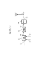
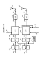
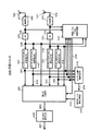
図1に、本実施の形態における送信装置の送信ユニットの構成の一例を示し、例えば無線基地局(以下、単に基地局と呼ぶ)に設けられている。送信ユニット100の変調部102は送信ディジタル信号101、フレーム構成信号生成部121で生成されたタイミング信号122を入力とし、送信ディジタル信号101に対してQPSK(Quadrature Phase Shift Keying)や16QAM(Quadrature Amplitude Modulation)等の直交変調処理を施すと共にタイミング信号122にしたがったフレーム構成(図3(A))とすることにより送信直交ベースバンド信号103を形成して出力する。拡散部104は送信直交ベースバンド信号103を入力とし、この送信直交ベースバンド信号103に対して所定の拡散符号を用いた拡散処理を施すことにより拡散信号105を形成して出力する。無線部106は拡散信号105を入力とし、拡散信号105に対してディジタルアナログ変換処理やアップコンバート等の所定の無線処理を施すことにより変調信号107を形成して出力する。
FIG. 1 shows an example of a configuration of a transmission unit of a transmission apparatus according to the present embodiment, and is provided in, for example, a radio base station (hereinafter simply referred to as a base station). The
送信パワー変更部108は、変調信号107、受信パワーから求めた係数125、固有値から求めた係数124を入力とし、変調信号107に係数125、124を乗じることにより送信信号109を得てこれを出力する。これにより、受信パワー及び固有値に基づいて変調信号107の送信パワーが決定される。送信信号109はアンテナ110から電波として出力される。
The transmission
変調部112は送信ディジタル信号111、タイミング信号122を入力とし、送信ディジタル信号111に対してQPSKや16QAM等の直交変調処理を施すと共にタイミング信号122にしたがったフレーム構成(図3(B))とすることにより送信直交ベースバンド信号113を形成して出力する。拡散部114は送信直交ベースバンド信号113を入力とし、この送信直交ベースバンド信号113に対して所定の拡散符号を用いた拡散処理を施すことにより拡散信号115を形成して出力する。因みに、拡散部114は拡散部104で用いた拡散符号と異なる拡散符号を用いて拡散処理を行う。無線部116は拡散信号115を入力とし、拡散信号115に対してディジタルアナログ変換処理やアップコンバート等の所定の無線処理を施すことにより変調信号117を形成して出力する。
The
送信パワー変更部118は、変調信号117、受信パワーから求めた係数126、固有値から求めた係数124を入力とし、変調信号117に係数126、124を乗じることにより送信信号119を得てこれを出力する。これにより、受信パワー及び固有値に基づいて変調信号117の送信パワーが決定される。送信信号119はアンテナ120から電波として出力される。
The transmission
このように本実施の形態の送信装置に設けられた送信ユニット100においては、各アンテナ110、120から送信する変調信号の送信電力を独立に変更できるようになっている。
As described above, in the transmission unit 100 provided in the transmission apparatus of the present embodiment, the transmission power of the modulated signal transmitted from each
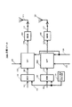
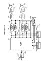
図2に、本実施の形態における送信装置の受信ユニットの構成の一例を示す。受信ユニット200は、図1の送信ユニット100と同じ基地局に設けられる。受信ユニット200の無線部203はアンテナ201で受信した受信信号202を入力とし、受信信号202に対してダウンコンバートやアナログディジタル変換等の所定の無線処理を施すことにより受信直交ベースバンド信号204を形成して出力する。復調部205は受信直交ベースバンド信号204を入力とし、受信直交ベースバンド信号204に対してQPSK復調や16QAM復調等の直交復調処理を施すことにより受信ディジタル信号206を形成して出力する。
FIG. 2 shows an example of the configuration of the reception unit of the transmission apparatus in this embodiment. The receiving unit 200 is provided in the same base station as the transmitting unit 100 in FIG. The
データ分離部207は受信ディジタル信号206を入力とし、受信ディジタル信号206をデータ208、電界強度推定情報209、チャネル変動推定情報210に分離して出力する。
The
受信パワーによる係数計算部211は電界強度推定情報209を入力とし、この電界強度推定情報209に基づいて、送信ユニット100の送信パワー変更部108、118で用いる係数125、126を算出して送信パワー変更部108、118に送出する。この係数125、126の求め方の詳細については後述する。
固有値による係数計算部214はチャネル変動推定情報210を入力とし、このチャネル変動推定情報210に基づいて、送信ユニット100の送信パワー変更部108、118で用いる係数124を算出して送信パワー変更部108、118に送出する。この係数124の求め方の詳細については後述する。
The coefficient calculation unit 214 based on the eigenvalue receives the channel
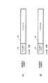
図3に、送信ユニット100の各アンテナ110、120から送信される各送信信号109(拡散信号A)、119(拡散信号B)の時間軸におけるフレーム構成の一例を示す。図3(A)に示す拡散信号Aと図3(B)に示す拡散信号Bは、各アンテナ110、120から同時に送信される。拡散信号Aのチャネル推定シンボル301と拡散信号Bのチャネル推定シンボル301は例えば互いに直交した符号とされており、端末の受信ユニットにおいて分離可能なものを用いる。これにより、端末の受信ユニットが、各拡散信号A、Bに含まれるチャネル推定シンボル301に基づき、アンテナ110、120から送信された信号のチャネル変動をそれぞれ推定することができるようになる。
FIG. 3 shows an example of a frame structure on the time axis of each transmission signal 109 (spread signal A) and 119 (spread signal B) transmitted from each
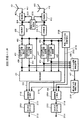
図4に、本実施の形態における受信装置の受信ユニットの構成の一例を示す。受信ユニット400は通信端末に設けられており、図1の送信ユニット100から送信された信号を受信復調する。受信ユニット400の無線部403はアンテナ401で受信した受信信号402を入力とし、受信信号402に対してダウンコンバートやアナログディジタル変換等の所定の無線処理を施すことにより受信直交ベースバンド信号404を形成して出力する。逆拡散部405は受信直交ベースバンド信号404を入力とし、受信直交ベースバンド信号404に対して図1の拡散部104及び拡散部114で用いた拡散符号と同じ拡散符号を用いた逆拡散処理を施すことにより逆拡散後の受信直交ベースバンド信号406を形成して出力する。
FIG. 4 shows an example of the configuration of the receiving unit of the receiving apparatus in this embodiment. The receiving unit 400 is provided in the communication terminal, and receives and demodulates the signal transmitted from the transmitting unit 100 in FIG. The
拡散信号Aのチャネル変動推定部407は逆拡散後の受信直交ベースバンド信号406を入力とし、チャネル推定シンボルに基づき拡散信号A(アンテナ110から送信された拡散信号)のチャネル変動を推定しチャネル変動推定信号408として出力する。これにより、アンテナ110とアンテナ401間のチャネル変動が推定される。拡散信号Bのチャネル変動推定部409は逆拡散後の受信直交ベースバンド信号406を入力とし、チャネル推定シンボルに基づき拡散信号B(アンテナ120から送信された拡散信号)のチャネル変動を推定しチャネル変動推定信号410として出力する。これによりアンテナ120とアンテナ401間のチャネル変動が推定される。
Channel
無線部413はアンテナ411で受信した受信信号412を入力とし、受信信号412に対してダウンコンバートやアナログディジタル変換等の所定の無線処理を施すことにより受信直交ベースバンド信号414を形成して出力する。逆拡散部415は受信直交ベースバンド信号414を入力とし、受信直交ベースバンド信号414に対して図1の拡散部104及び拡散部114で用いた拡散符号と同じ拡散符号を用いた逆拡散処理を施すことにより逆拡散後の受信直交ベースバンド信号416を形成して出力する。
The
拡散信号Aのチャネル変動推定部417は逆拡散後の受信直交ベースバンド信号416を入力とし、チャネル推定シンボルに基づき拡散信号A(アンテナ110から送信された拡散信号)のチャネル変動を推定しチャネル変動推定信号418として出力する。これにより、アンテナ110とアンテナ411間のチャネル変動が推定される。拡散信号Bのチャネル変動推定部419は逆拡散後の受信直交ベースバンド信号416を入力とし、チャネル推定シンボルに基づき拡散信号B(アンテナ120から送信された拡散信号)のチャネル変動を推定しチャネル変動推定信号420として出力する。これによりアンテナ120とアンテナ411間のチャネル変動が推定される。
Channel
信号処理部421は受信直交ベースバンド信号406、416、拡散信号Aのチャネル変動推定信号408、418、拡散信号Bのチャネル変動推定信号410、420を入力とし、チャネル変動推定値408、410、418、420を要素とするチャネル変動行列の逆行列を用いた演算を行うことにより、拡散信号Aの受信直交ベースバンド信号422、拡散信号Bの受信直交ベースバンド信号423を出力する。このチャネル変動行列の詳細については後述する。
The
受信電界強度推定部424は受信直交ベースバンド信号406、416を入力とし、これらの信号の受信電界強度を求めて受信電界強度推定情報425を出力する。なおこの実施の形態では、受信電界強度を受信直交ベースバンド信号から求めているがこれに限ったものではなく、受信信号から求めてもよい。また受信電界強度は、拡散信号A、拡散信号Bについて別々に受信電界強度を求めてもよいし、合成波の受信電界強度を求めてもよい。
Reception field
チャネル変動情報生成部426は拡散信号Aのチャネル変動推定信号408、418、拡散信号Bのチャネル変動推定信号410、420を入力とし、チャネル変動推定情報427を形成して出力する。
The channel fluctuation
図5に、本実施の形態における受信装置の送信ユニットの構成の一例を示す。送信ユニット500は受信ユニット400と同じ通信端末に設けられている。送信ユニット500の情報生成部504はデータ501、受信電界強度推定情報425、チャネル変動推定情報427を入力とし、これらを所定の順序で配列して送信ディジタル信号505を出力する。変調信号生成部506は送信ディジタル信号505を入力とし、送信ディジタル信号505に対して変調処理を施すことにより変調信号507を形成して出力する。無線部508は変調信号507を入力とし、変調信号507に対してディジタルアナログ変換処理やアップコンバート等の所定の無線処理を施すことにより送信信号509を形成して出力する。送信信号509はアンテナ510から電波として出力される。
FIG. 5 shows an example of the configuration of the transmission unit of the reception apparatus in this embodiment. The
図6に、送信ユニット500から送信される送信信号のフレーム構成の一例を示す。図中、601はチャネル変動推定情報シンボル、602は電界強度推定情報シンボル、603はデータシンボルである。
FIG. 6 shows an example of a frame configuration of a transmission signal transmitted from the
図7に、送信信号と受信信号の関係の一例を示す。送信アンテナ110から送信された変調信号Ta(t)は、チャネル変動h11(t)、h12(t)を受けた後にアンテナ401、402で受信される。また送信アンテナ120から送信された変調信号Tb(t)は、チャネル変動h21(t)、h22(t)を受けた後にアンテナ401、402で受信される。
FIG. 7 shows an example of the relationship between the transmission signal and the reception signal. Modulated signal Ta (t) transmitted from transmitting
次に、図1〜図7を用いて本実施の形態における送信装置および受信装置の動作について詳しく説明する。 Next, operations of the transmission apparatus and the reception apparatus in the present embodiment will be described in detail with reference to FIGS.
先ず、基地局(送信装置)の送信動作について説明する。図1に示す基地局の送信ユニット100で重要な動作は、各アンテナ110、120から送信する変調信号の送信パワーを各アンテナ110、120で独立に制御する点である。このため送信ユニット100においては、送信パワー変更部108、118で送信信号に係数を乗算する。
First, the transmission operation of the base station (transmission apparatus) will be described. An important operation in the transmission unit 100 of the base station shown in FIG. 1 is that the transmission power of the modulated signal transmitted from each
ここで送信パワー変更部108での動作を詳しく説明する。受信パワーから求めた乗算係数125の値をCa、変調信号107をXa(t)、固有値から求めた係数124をDとすると、送信パワー変更部108は、次式で表すように送信信号109の送信パワーXa’(t)を制御する。
Here, the operation of the transmission
![]()
![]()
![]()
![]()
また受信パワーから求めた係数を、各送信アンテナの送信パワー変更部108、118で独立して乗算するようにしたことにより、一段と効果的に受信品質を向上させることができる。なぜなら、受信パワーから求めた係数は、受信端末のアンテナでの各変調信号の受信電界強度を向上させるための送信パワー制御に相当するからである。
In addition, since the coefficient obtained from the reception power is multiplied independently by the transmission
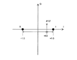
次に、基地局(送信装置)の受信動作について説明する。図7に示すように、tを時間とし、アンテナ110からの変調信号をTa(t)、アンテナ120からの変調信号をTb(t)、アンテナ401の受信信号をR1(t)、アンテナ402の受信信号をR2(t)、チャネル変動をそれぞれ、h11(t)、h12(t)、h21(t)、h22(t)とすると、次式のような関係が成立する。つまり、各アンテナ受信信号R1(t)、R2(t)と各変調信号Ta(t)、Tb(t)を、チャネル変動値h11(t)、h12(t)、h21(t)、h22(t)を要素とするチャネル変動行列によって関連付けることができる。
Next, the receiving operation of the base station (transmitting device) will be described. As shown in FIG. 7, t is time, the modulation signal from the

例えば、係数125を、h11(t)、h21(t)の推定値から求める。なぜなら、h11(t)、h21(t)は図1のアンテナ110から出力される信号の送信パワーで決定される変動値であるからである。同様に、係数126を、h12(t)、h22(t)の推定値から求める。なぜなら、h12(t)、h22(t)は図1のアンテナ120から出力される信号の送信パワーで決定される変動値であるからである。
For example, the
つまり、R1(t)とR2(t)の受信電界強度は共にアンテナ110からの信号とアンテナ120からの信号が合成された信号の電界強度なので、その受信電界強度のみに基づいて係数125、126を決定すると、各アンテナからの信号パワーを適切に調整するには不十分である。そこで本実施の形態においては、受信電界強度に加えて、各送信信号の受信時のチャネル変動値h11(t)、h21(t)及びh12(t)、h22(t)を用いて各アンテナ110、120から送信する信号パワーを制御するための係数125、126を決定する。これにより、各アンテナ110、120から送信される各信号の受信時のパワーを適切なものとすることができる。
That is, since the received electric field strengths of R1 (t) and R2 (t) are both the electric field strengths of the signal obtained by combining the signal from the
具体的に説明すると、受信電界強度が小さい場合には、当然送信電力が大きくなるように係数125、126の値を大きくする。さらにチャネル変動値h11(t)、h21(t)の大きさが小さいほど、アンテナ110で用いる係数125の値を大きくする。同様にチャネル変動値h12(t)、h22(t)の大きさが小さいほど、アンテナ120で用いる係数126の値を大きくする。
More specifically, when the received electric field strength is small, the values of the
固有値による係数計算部214は、端末から受け取ったチャネル変動h11(t)、h12(t)、h21(t)、h22(t)の推定値を要素とする(3)式のチャネル変動行列の固有値を計算し、固有値のパワーのうち最もパワーの小さい値に基づいて係数124を求める。
The coefficient calculation unit 214 based on eigenvalues is an eigenvalue of the channel fluctuation matrix of Equation (3) whose elements are estimated values of channel fluctuations h11 (t), h12 (t), h21 (t), and h22 (t) received from the terminal. , And the
ここで固有値を求める計算方法としては、例えばJacobi法、Givens法、Housefolde法、QR法、QL法、陰的シフトつきQL法、逆反復法があり、本発明ではどのような計算方法を用いてもよい。また固有値のパワーとは、固有値をa+bj(a、b:実数、j:虚数)のように表した場合、a2+b2で表される値である。これらは、後述する他の実施の形態でも同様である。 Here, the calculation method for obtaining the eigenvalue includes, for example, the Jacobi method, Givens method, Housefolde method, QR method, QL method, QL method with implicit shift, and inverse iteration method. In the present invention, any calculation method is used. Also good. The power of the eigenvalue is a value represented by a 2 + b 2 when the eigenvalue is represented as a + bj (a, b: real number, j: imaginary number). The same applies to other embodiments described later.
次に、通信端末(受信装置)の受信動作について説明する。図4の受信ユニット400の拡散信号Aのチャネル変動推定部407は図3(A)に示す拡散信号Aのチャネル推定シンボル301から、拡散信号Aのチャネル変動つまり(3)式のh11(t)を推定し、推定結果を拡散信号Aのチャネル変動推定信号408として出力する。拡散信号Bのチャネル変動推定部409は図3(B)に示す拡散信号Bのチャネル推定シンボル301から、拡散信号Bのチャネル変動つまり(3)式のh12(t)を推定し、推定結果を拡散信号Bのチャネル変動推定信号410として出力する。
Next, the receiving operation of the communication terminal (receiving device) will be described. The channel
拡散信号Aのチャネル変動推定部417は図3(A)に示す拡散信号Aのチャネル推定シンボル301から、拡散信号Aのチャネル変動つまり(3)式のh21(t)を推定し、推定結果を拡散信号Aのチャネル変動推定信号418として出力する。拡散信号Bのチャネル変動推定部419は図3(B)に示す拡散信号Bのチャネル推定シンボル301から、拡散信号Bのチャネル変動つまり(3)式のh22(t)を推定し、推定結果を拡散信号Bのチャネル変動推定信号420として出力する。
The channel
信号処理部421は、(3)式においてチャネル変動行列の逆行列を両辺に乗じる逆行列演算を行うことで、拡散信号A、Bの受信直交ベースバンド信号422、423を求める。これにより、受信直交ベースバンド信号422と受信直交ベースバンド信号423が分離される。チャネル変動情報生成部426は、拡散信号Aのチャネル変動推定信号408、418、拡散信号Bのチャネル変動推定信号410、420として、推定されたチャネル変動h11(t)、h12(t)、h21(t)、h22(t)を入力し、これらをチャネル変動推定情報427として出力する。
The
かくして以上の構成によれば、マルチアンテナ送信を行う送信装置において、各アンテナ110、120から送信した変調信号の受信時のチャネル変動値h11(t)、h12(t)、h21(t)、h22(t)を通信相手局から受け取り、このチャネル変動値h11(t)、h12(t)、h21(t)、h22(t)に基づき各アンテナ110、120から送信する変調信号の送信電力を各アンテナ110、120で独立に制御するようにしたことにより、各変調信号の受信時の受信電界強度を適切なものとすることができるので、各変調信号の受信品質を向上させることができる。
Thus, according to the above configuration, in a transmission apparatus that performs multi-antenna transmission, channel fluctuation values h11 (t), h12 (t), h21 (t), h22 at the time of receiving modulated signals transmitted from the
加えて、チャネル変動値h11(t)、h12(t)、h21(t)、h22(t)を要素とするチャネル変動行列の固有値も加味して送信電力を制御するようにしたことにより、実効受信電界強度を大きくすることができるので、各変調信号の受信品質を一段と向上させることができる。 In addition, the transmission power is controlled by taking into account the eigenvalues of the channel variation matrix having the channel variation values h11 (t), h12 (t), h21 (t), and h22 (t) as elements. Since the reception electric field strength can be increased, the reception quality of each modulated signal can be further improved.
なお上述した実施の形態では、基地局つまり送信側で各アンテナ110、120の送信電力を制御するための係数124、125、126を決定する場合について述べたが、本発明はこれに限らず、端末つまり受信側で係数124、125、126を決定し、決定した係数を送信側にフィードバックするようにしてもよい。これは、以下に説明する他の実施の形態についても同様である。
In the above-described embodiment, the case where the base station, that is, the transmission side, determines the
また上述した実施の形態では、アンテナ数が2つで、多重される変調信号数が2つの場合について述べたが、本発明はこれに限らず、要は複数アンテナを用い各アンテナから異なる変調信号を送信する場合に広く適用できる。また例えばアダプティブアレイアンテナのように各変調信号を送信する1つのアンテナ(例えばアンテナ110)を複数のアンテナから構成するようにしてもよい。これは、以下に説明する他の実施の形態についても同様である。 In the above-described embodiment, the case where the number of antennas is two and the number of modulated signals to be multiplexed is two has been described. However, the present invention is not limited to this, and in short, the modulation signals differ from each antenna using a plurality of antennas. It can be widely applied when transmitting. Further, for example, one antenna (for example, the antenna 110) that transmits each modulation signal, such as an adaptive array antenna, may be configured by a plurality of antennas. The same applies to other embodiments described below.
また上述した実施の形態では、受信電界強度と記述しているが、受信電界強度を、受信レベル、受信強度、受信パワー、受信振幅又はキャリアパワー対ノイズパワーなどに置き換えても同様に実施することができる。これは、以下に説明する他の実施の形態についても同様である。 In the above-described embodiment, the reception electric field strength is described. However, the reception electric field strength is replaced with a reception level, reception intensity, reception power, reception amplitude, carrier power versus noise power, or the like. Can do. The same applies to other embodiments described below.
また上述した実施の形態では、チャネル変動を推定するために送信するシンボルをチャネル推定シンボル301(図3)と呼んだが、チャネル推定シンボル301をパイロットシンボル、プリアンブル、制御シンボル、既知シンボル又はユニークワードと呼んでもよいし、他の名称で呼んでもよい。また、図6のチャネル変動推定情報シンボル601、電界強度推定情報シンボル602は、制御シンボルと呼んでもよいし、他の名称で呼んでもよい。つまり、これらのシンボルを用いても上述の実施の形態と同様に本発明を実施できる。これは、以下に説明する他の実施の形態についても同様である。
In the embodiment described above, a symbol to be transmitted to estimate channel fluctuation is called a channel estimation symbol 301 (FIG. 3). However, the
また上述した実施の形態では、スペクトル拡散通信方式を例に説明したが、これに限ったものではなく、例えば、拡散部を有しないシングルキャリア方式、OFDM方式においても同様に実施することができる。シングルキャリア方式の場合、拡散部104、114(図1)、逆拡散部405、415(図4)を有しない構成となる。これは、スペクトル拡散方式を例にとって説明する以下の全ての実施の形態についても同様である。また本発明をOFDM方式に適用した場合については、実施の形態2において詳しく説明する。
In the above-described embodiment, the spread spectrum communication method has been described as an example. However, the present invention is not limited to this. For example, the present invention can be similarly applied to a single carrier method and an OFDM method that do not have a spreading unit. In the case of the single carrier method, the
さらに本発明の送信装置及び受信装置の構成は、図1、図2、図4、図5の構成に限ったものではない。例えば上述した実施の形態では、送信パワー変更部108、118を設け、この送信パワー変更部によって、固有値から求めた係数124、受信パワーから求めた係数125、126に基づいて各アンテナ110、120から送信する変調信号の送信電力を各アンテナ110、120で独立に制御する場合について説明したが、要は、各アンテナでの変調信号を独立に制御すればよいのであって、その構成は図1に示すものに限らない。
Furthermore, the configurations of the transmission device and the reception device of the present invention are not limited to the configurations of FIGS. 1, 2, 4, and 5. For example, in the above-described embodiment, the transmission
図8に、本実施の形態における基地局の送信ユニットの別の構成例を示す。図8では、図1の送信ユニット100と同様に動作するものについては同一符号を付した。図8の送信ユニット700と図1の送信ユニット100との違いは、図1の送信ユニット100が送信パワー変更部108、118によって各アンテナから送信する変調信号のパワーを制御したのに対して、拡散部701、702によって各アンテナから送信する変調信号のパワーを制御するようにしたことである。
FIG. 8 shows another configuration example of the transmission unit of the base station in the present embodiment. In FIG. 8, components that operate in the same manner as the transmission unit 100 of FIG. The transmission unit 700 in FIG. 8 differs from the transmission unit 100 in FIG. 1 in that the transmission unit 100 in FIG. 1 controls the power of the modulated signal transmitted from each antenna by the transmission
具体的には、拡散部701は送信直交ベースバンド信号103、受信パワーから求めた係数125、固有値から求めた係数124を入力とし、これらの係数125、124に応じたパワーの拡散信号105を出力する。同様に、拡散部702は送信直交ベースバンド信号113、受信パワーから求めた係数126、固有値から求めた係数124を入力とし、これらの係数126、124に応じたパワーの拡散信号115を出力する。
Specifically, the spreading
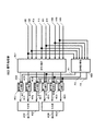
図9に、拡散部701、702の構成例を示す。拡散機能部804はチャネルXの送信直交ベースバンド信号801、チャネルYの送信直交ベースバンド信号802、チャネルZの送信直交ベースバンド信号803を入力とし、これらを異なる拡散コードを用いて拡散処理することによりチャネルXの拡散信号805、チャネルYの拡散信号806、チャネルZの拡散信号807を形成して出力する。ここでチャネルXの信号とは端末X宛の信号を示し、チャネルYの信号とは端末Y宛の信号を示し、チャネルZの信号とは端末Z宛の信号を示すものとする。つまり、送信ユニット700は、各アンテナ110、120からそれぞれ3つの端末X、Y、Z宛の拡散変調信号を出力する。
FIG. 9 shows a configuration example of the
係数乗算機能部810はチャネルXの拡散信号805、チャネルYの拡散信号806、チャネルZの拡散信号807、受信パワーから求めた係数125(126)、固有値から求めた係数124を入力とし、これらの係数125(126)、124に応じた係数を乗算することにより係数乗算後のチャネルXの拡散信号811、係数乗算後のチャネルYの拡散信号812、係数乗算後のチャネルZの拡散信号813を形成して出力する。
The coefficient
ここでチャネルXの拡散信号805に乗じる、受信パワーから求めた係数125(126)、固有値から求めた係数124は、端末Xから送られてきた受信電界強度推定情報、チャネル変動推定情報に基づいて求められたものである。またチャネルYの拡散信号806に乗じる、受信パワーから求めた係数125(126)、固有値から求めた係数124は、端末Yから送られてきた受信電界強度推定情報、チャネル変動推定情報に基づいて求められたものである。またチャネルZの拡散信号807に乗じる、受信パワーから求めた係数125(126)、固有値から求めた係数124は、端末Zから送られてきた受信電界強度推定情報、チャネル変動推定情報に基づいて求められたものである。 Here, the coefficient 125 (126) obtained from the received power and the coefficient 124 obtained from the eigenvalue multiplied by the spread signal 805 of the channel X are based on the received electric field strength estimation information and the channel fluctuation estimation information transmitted from the terminal X. It is what was sought. Further, the coefficient 125 (126) obtained from the received power and the coefficient 124 obtained from the eigenvalue multiplied by the spread signal 806 of the channel Y are obtained based on the received electric field strength estimation information and the channel fluctuation estimation information sent from the terminal Y. It is what was done. The coefficient 125 (126) obtained from the received power and the coefficient 124 obtained from the eigenvalue multiplied by the spread signal 807 of the channel Z are obtained based on the received electric field strength estimation information and the channel fluctuation estimation information sent from the terminal Z. It is what was done.
加算機能部814は、係数乗算後のチャネルXの拡散信号811、係数乗算後のチャネルYの拡散信号812、係数乗算後のチャネルZの拡散信号813を加算し、拡散信号105(115)として出力する。
The
このように送信ユニット700は、複数の端末宛の送信信号を同時に生成するようになっている。この際、送信ユニット700は、各端末から受信電界強度推定情報及びチャネル変動推定情報を受け取り、各端末用の受信パワーから求めた係数、固有値から求めた係数を求め、各端末によって異なるこれらの係数を各端末宛の拡散変調信号に乗じるようにしたことにより、各アンテナ独立にかつ各端末宛の変調信号独立に送信パワーを制御できるようになる。この結果、複数アンテナから複数端末宛の変調信号を同時に送信する場合において、複数端末全てにおける実効受信電力を最適化して、伝送速度を下げることなく複数端末全ての受信品質を向上させることができるようになる。 As described above, the transmission unit 700 is configured to simultaneously generate transmission signals addressed to a plurality of terminals. At this time, the transmission unit 700 receives the received electric field strength estimation information and the channel fluctuation estimation information from each terminal, obtains a coefficient obtained from the received power for each terminal, a coefficient obtained from the eigenvalue, and these coefficients that are different for each terminal. Is multiplied by the spread modulation signal addressed to each terminal, so that the transmission power can be controlled independently of each antenna and independently of the modulation signal addressed to each terminal. As a result, when simultaneously transmitting modulated signals addressed to a plurality of terminals from a plurality of antennas, it is possible to optimize the effective received power in all of the plurality of terminals and improve the reception quality of all of the plurality of terminals without reducing the transmission rate. become.
かくして本実施の形態によれば、受信装置からチャネル変動情報及び受信電界強度情報等の実効受信電力の指標となる情報をフィードバック情報として受け取り、この情報に基づいて各アンテナから送信する変調信号の送信電力を各アンテナ独立に変更するようにしたことにより、各アンテナから送信される変調信号の実効受信電力を増加させることができ、変調信号の受信品質を向上し得る送信装置を実現できる。 Thus, according to the present embodiment, information serving as an index of effective received power, such as channel fluctuation information and received electric field strength information, is received as feedback information from the receiving apparatus, and transmission of modulated signals transmitted from each antenna based on this information By changing the power independently for each antenna, the effective reception power of the modulated signal transmitted from each antenna can be increased, and a transmission apparatus capable of improving the reception quality of the modulated signal can be realized.
(実施の形態2)
本実施の形態では、各アンテナから送信する変調信号の送信電力を各アンテナで独立に、かつ、各キャリアごとに独立に変更する送信装置について説明する。
(Embodiment 2)
In the present embodiment, a description will be given of a transmission apparatus that changes the transmission power of a modulated signal transmitted from each antenna independently for each antenna and independently for each carrier.
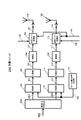
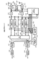
図10に、本実施の形態における送信装置の送信ユニットの構成の一例を示す。送信ユニット1000は例えば基地局に設けられている。基地局の受信ユニットは例えば図2に示すように構成されており、基地局と通信を行う端末の送信ユニットは例えば図5に示すように構成されており、端末の送信ユニットから送信される送信信号のフレーム構成は例えば図6に示すようになっており、これらは既に実施の形態1で説明したのでその説明は省略する。
FIG. 10 shows an example of the configuration of the transmission unit of the transmission apparatus in this embodiment. The
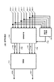
送信ユニット1000は、変調部102に、送信ディジタル信号101、タイミング信号122を入力し、送信ディジタル信号101に対してQPSKや16QAM等の直交変調処理を施すと共にタイミング信号122にしたがったフレーム構成(図11(A))とすることにより送信直交ベースバンド信号103を形成して出力する。IDFT1001は送信直交ベースバンド信号103、受信パワーから求めた係数125、固有値から求めた係数124を入力とし、係数125、124に基づいて送信パワーを変更すると共に逆フーリエ変換を行い、逆フーリエ変換後の信号1002を出力する。
The
同様に、送信ユニット1000は、変調部112に、送信ディジタル信号111、タイミング信号122を入力し、送信ディジタル信号111に対してQPSKや16QAM等の直交変調処理を施すと共にタイミング信号122にしたがったフレーム構成(図11(B))とすることにより送信直交ベースバンド信号113を形成して出力する。IDFT1003は、送信直交ベースバンド信号113、受信パワーから求めた係数126、固有値から求めた係数124を入力とし、係数126、124に基づいて送信パワーを変更すると共に逆フーリエ変換を行い、逆フーリエ変換後の信号1004を出力する。
Similarly, the
図11に、送信ユニット1000から送信される変調信号のフレーム構成例を示す。図11(A)はアンテナ110から送信される信号(チャネルA)のフレーム構成を示し、図11(B)はアンテナ120から送信される信号(チャネルB)のフレーム構成を示す。この例では、推定用シンボル1101は特定の時刻1に全てのサブキャリアに配置されて送信され、情報シンボル1102は他の時刻2〜9に送信されるようになっている。
FIG. 11 shows a frame configuration example of a modulated signal transmitted from the
図12に、本実施の形態における受信装置の受信ユニットの構成の一例を示す。受信ユニット1200は通信端末に設けられており、図10の送信ユニット1000から送信された信号を受信復調する。受信ユニット1200の無線部1203はアンテナ1201で受信した受信信号1202を入力とし、受信信号1202に対してダウンコンバートやアナログディジタル変換等の所定の無線処理を施すことにより受信直交ベースバンド信号1204を形成して出力する。フーリエ変換部(dft)1205は受信直交ベースバンド信号1204を入力とし、受信直交ベースバンド信号1204に対してフーリエ変換処理を施すことによりフーリエ変換後の信号1206を形成して出力する。
FIG. 12 illustrates an example of a configuration of a reception unit of the reception device in this embodiment. The receiving unit 1200 is provided in the communication terminal, and receives and demodulates the signal transmitted from the
チャネルAのチャネル変動推定部1207はフーリエ変換後の信号1206を入力とし、チャネルAのチャネル推定用シンボルに基づきチャネルAの信号(アンテナ110から送信されたOFDM信号)のチャネル変動を推定しチャネル変動推定群信号1208として出力する。これにより、アンテナ110とアンテナ1201間のチャネル変動が推定される。チャネルBのチャネル変動推定部1209はフーリエ変換後の信号1206を入力とし、チャネルBのチャネル推定用シンボルに基づきチャネルBの信号(アンテナ120から送信されたOFDM信号)のチャネル変動を推定しチャネル変動推定群信号1210として出力する。これにより、アンテナ120とアンテナ1201間のチャネル変動が推定される。
Channel A channel
無線部1213はアンテナ1211で受信した受信信号1212を入力とし、受信信号1212に対してダウンコンバートやアナログディジタル変換等の所定の無線処理を施すことにより受信直交ベースバンド信号1214を形成して出力する。フーリエ変換部(dft)1215は受信直交ベースバンド信号1214を入力とし、受信直交ベースバンド信号1214に対してフーリエ変換処理を施すことによりフーリエ変換後の信号1216を形成して出力する。
The
チャネルAのチャネル変動推定部1217はフーリエ変換後の信号1216を入力とし、チャネルAのチャネル推定用シンボルに基づきチャネルAの信号(アンテナ110から送信されたOFDM信号)のチャネル変動を推定しチャネル変動推定群信号1218として出力する。これにより、アンテナ110とアンテナ1211間のチャネル変動が推定される。チャネルBのチャネル変動推定部1219はフーリエ変換後の信号1216を入力とし、チャネルBのチャネル推定用シンボルに基づきチャネルBの信号(アンテナ120から送信されたOFDM信号)のチャネル変動を推定しチャネル変動推定群信号1220として出力する。これにより、アンテナ120とアンテナ1211間のチャネル変動が推定される。
Channel A channel
信号処理部1221はフーリエ変換後の信号1206、1216、チャネルAのチャネル変動推定信号1208、1218、チャネルBのチャネル変動推定信号1210、1220を入力とし、チャネル変動推定値1208、1218、1210、1220を要素とするチャネル変動行列の逆行列を用いた演算を行うことにより、チャネルAの受信直交ベースバンド信号群1222、チャネルBの受信直交ベースバンド信号群1223を出力する。
The
チャネルAの復調部1224はチャネルAの受信直交ベースバンド信号群1222を入力とし、その信号に対して送信ユニット1000(図10)の変調部102に対応する復調処理を施すことにより受信ディジタル信号1225を形成して出力する。チャネルBの復調部1226はチャネルBの受信直交ベースバンド信号群1223を入力とし、その信号に対して送信ユニット1000の変調部112に対応する復調処理を施すことにより受信ディジタル信号1227を形成して出力する。
The channel
受信電界強度推定部1228はフーリエ変換後の信号1206、1216を入力とし、これらの信号の受信電界強度を求めて受信電界強度推定情報1229を出力する。
Received electric field
チャネル変動推定部1230はチャネルAのチャネル変動推定信号群1208、1218、チャネルBのチャネル変動推定信号群1210、1220を入力とし、チャネル変動推定情報1231を形成して出力する。
Channel
図13に、図10の送信ユニット1000に設けられたIDFT1001、1003の構成例を示す。ここでIDFT1001とIDFT1003は同様の構成なので、IDFT1001について説明する。
FIG. 13 shows a configuration example of
IDFT1001は送信パワー変更部1307を有する。送信パワー変更部1307は、キャリア1の送信直交ベースバンド信号1301、キャリア2の送信直交ベースバンド信号1302、キャリア3の送信直交ベースバンド信号1303、キャリア4の送信直交ベースバンド信号1304、受信パワーから求めた係数125、固有値から求めた係数124を入力とし、各キャリアの送信直交ベースバンド信号1301〜1304に係数125、124を乗ずることにより、係数乗算後のキャリア1の送信直交ベースバンド信号1308、係数乗算後のキャリア2の送信直交ベースバンド信号1309、係数乗算後のキャリア3の送信直交ベースバンド信号1310、係数乗算後のキャリア4の送信直交ベースバンド信号1311を得てこれを出力する。
The
ここでこの実施の形態における受信パワーから求めた係数125、固有値から求めた係数124は、キャリアごとに求められたものである。そして送信パワー変更部1307は、互いに対応するキャリアの送信直交ベースバンド信号と係数125、124とを乗算することにより、キャリアごとに送信パワーを変更するようになっている。
Here, the
逆フーリエ変換部(IDFT部)1312は、係数乗算後のキャリア1の送信直交ベースバンド信号1308、係数乗算後のキャリア2の送信直交ベースバンド信号1309、係数乗算後のキャリア3の送信直交ベースバンド信号1310、係数乗算後のキャリア4の送信直交ベースバンド信号1311を入力とし、これらの信号に対して逆フーリエ変換処理を施すことにより逆フーリエ変換後の信号1313を得てこれを出力する。
The inverse Fourier transform unit (IDFT unit) 1312 includes a transmission orthogonal baseband signal 1308 of
次に、本実施の形態における送信装置および受信装置の動作について詳しく説明する。なおここでは、説明を簡単化するために、実施の形態1で用いた図面(図2、図6)を流用する。
Next, operations of the transmission device and the reception device in the present embodiment will be described in detail. Here, in order to simplify the description, the drawings (FIGS. 2 and 6) used in
先ず、基地局(送信装置)の動作について説明する。図10に示す基地局の送信ユニット1000で重要な動作は、第1に、各アンテナ110、120から送信するOFDM信号の送信パワーを各アンテナ110、120で独立に制御する点であり、第2に、キャリアごとに送信パワーを制御する点である。このため送信ユニット1000は、IDFT1001、1003において送信直交ベースバンド信号103、113の送信パワーを変更するために係数を乗算する。
First, the operation of the base station (transmitting device) will be described. An important operation in the
その詳しい動作を図13を用いて説明する。図13は、図10のIDFT1001、1003の詳細の構成を示している。図10の送信直交ベースバンド群103、113は、図13のキャリア1の送信直交ベースバンド信号1301、キャリア2の送信直交ベースバンド信号1302、キャリア3の送信直交ベースバンド信号1303、キャリア4の送信直交ベースバンド信号1304に相当し、サブキャリアごとに直交ベースバンド信号が存在する。
The detailed operation will be described with reference to FIG. FIG. 13 shows a detailed configuration of the
そして送信パワー変更部1307は、互いに対応するキャリアの送信直交ベースバンド信号と係数125、124とを乗算することにより、キャリアごとに送信パワーを変更するようになっている。つまり、受信パワーから求めた係数125、固有値126は、各キャリアごとの係数で構成されている。なお送信パワー変更部1307による係数乗算方法は、キャリアごとに係数を乗算することが異なるだけで、基本的には実施の形態1で説明したとおりである。
The transmission
次に、基地局(送信装置)の受信動作について説明する。この実施の形態の場合、図2の受信ユニット200は、通信端末(受信装置)からキャリアごとの電界強度推定情報209を受け取ると共に、キャリアごとのチャネル推定情報210を受け取る。そして受信パワーによる係数計算部211によってキャリアごとの係数125、126を求め、固有値による係数計算部214によってキャリアごとの係数124を求める。このようにして、通信端末(受信装置)から送られてきたキャリアごとの電界強度推定情報209、チャネル変動推定情報210を基にして、キャリアごとの係数125、126、124を求める。なお受信パワーによる係数計算部211及び固有値による係数計算部214による係数算出方法は、キャリアごとに係数を算出することが異なるだけで、基本的には実施の形態1で説明したとおりである。
Next, the receiving operation of the base station (transmitting device) will be described. In the case of this embodiment, the receiving unit 200 of FIG. 2 receives the electric field
次に、通信端末(受信装置)の受信動作について説明する。図12の受信ユニット1200のフーリエ変換部(dft)1205、1215から出力されるフーリエ変換後の信号1206、1216は、各キャリアごとの信号で構成されている。
Next, the receiving operation of the communication terminal (receiving device) will be described.
チャネルAのチャネル変動推定部1207は、図11(A)の推定用シンボル1101を検出し、キャリアごとにチャネル変動を推定する。つまり、キャリアごとに(3)式のh11(t)を推定し、チャネルAのチャネル変動推定信号群1208として出力する。チャネルBのチャネル変動推定部1209は、図11(B)の推定用シンボル1101を検出し、キャリアごとにチャネル変動を推定する。つまり、キャリアごとに(3)式のh12(t)を推定し、チャネルBのチャネル変動推定信号群1210として出力する。
Channel A channel
チャネルAのチャネル変動推定部1217は、図11(A)の推定用シンボル1101を検出し、キャリアごとにチャネル変動を推定する。つまり、キャリアごとに(3)式のh21(t)を推定し、チャネルAのチャネル変動推定信号群1218として出力する。チャネルBのチャネル変動推定部1219は、図11(B)の推定用シンボル1101を検出し、キャリアごとにチャネル変動を推定する。つまり、キャリアごとに(3)式のh22(t)を推定し、チャネルBのチャネル変動推定信号群1219として出力する。
Channel A channel
受信電界強度推定部1228は、フーリエ変換後の信号1206、1216を入力とし、各キャリアごとに受信電界強度を求め、受信電界強度推定信号1229として出力する。
Received electric field
チャネル変動推定部1230は、チャネルAのチャネル変動推定信号群1208、1218、チャネルBのチャネル変動推定信号群1210、1220を入力とし、各キャリアごとのチャネル変動推定情報を生成し、チャネル変動推定情報1231として出力する。
Channel
このようにして形成したキャリアごとの受信電界強度推定情報、キャリアごとのチャネル変動推定情報は、図5に示すような送信ユニット500によって基地局にフィードバック情報として送られる。なお図5の受信電界強度推定情報425は図12の1229に対応し、図5のチャネル変動推定情報427は図12の1231に対応する。
The reception field strength estimation information for each carrier and the channel fluctuation estimation information for each carrier formed in this way are sent as feedback information to the base station by the
かくして本実施の形態によれば、複数アンテナからマルチキャリア信号を送信する場合に、受信装置からキャリアごとのチャネル変動情報及びキャリアごとの受信電界強度情報等の実効受信電力の指標となる情報をフィードバック情報として受け取り、この情報に基づいて各アンテナから送信するマルチキャリア信号の送信電力を各アンテナ独立に、かつ各キャリア独立に変更するようにしたことにより、各アンテナから送信されるマルチキャリア信号の実効受信電力をキャリアごとに増加させることができ、マルチキャリア信号の誤り率特性を全てのキャリアに亘って向上し得る送信装置を実現できる。 Thus, according to the present embodiment, when a multicarrier signal is transmitted from a plurality of antennas, information that serves as an index of effective received power, such as channel fluctuation information for each carrier and received field strength information for each carrier, is fed back from the receiving device. By changing the transmission power of the multicarrier signal transmitted from each antenna based on this information independently for each antenna and each carrier independently, the effective multicarrier signal transmitted from each antenna is changed. The reception power can be increased for each carrier, and a transmission apparatus that can improve the error rate characteristics of a multicarrier signal over all carriers can be realized.
なおこの実施の形態では、IDFT1001、1003でキャリマルチキャリアアごとの送信パワーを変える場合について説明したが、送信パワーを変更するのはIDFT1001、1003でなくてもよく、例えば変調部102、112や無線部106、116で変えるようにしてもよい。
In this embodiment, the case where the
またこの実施の形態ではOFDM方式を例にとって説明したが、方式や、OFDM処理と拡散処理とを組み合わせた方式(例えばOFDM−CDMA方式)についても同様に実施することができる。 In this embodiment, the OFDM method has been described as an example. However, a method and a method combining OFDM processing and spreading processing (for example, OFDM-CDMA method) can be similarly implemented.
(実施の形態3)
本実施の形態では、複数のアンテナから送信された複数の変調信号を、複数のアンテナで受信する受信装置において、受信アンテナを選択し、選択した受信アンテナからの受信信号のみを用いて受信信号の復調を行う受信装置について説明する。
(Embodiment 3)
In the present embodiment, in a receiving apparatus that receives a plurality of modulated signals transmitted from a plurality of antennas using a plurality of antennas, the receiving antenna is selected, and only the received signals from the selected receiving antennas are used. A receiving apparatus that performs demodulation will be described.
具体的には、複数のアンテナ受信信号の組み合わせを作り、各組み合わせごとにチャネル変動行列を形成し、組み合わせごとのチャネル変動行列の固有値を算出し、固有値の最小パワーが最も大きい組み合わせのアンテナ受信信号を選択して復調処理を行うようにする。 Specifically, a combination of a plurality of antenna reception signals is created, a channel variation matrix is formed for each combination, an eigenvalue of the channel variation matrix for each combination is calculated, and an antenna reception signal of a combination having the largest eigenvalue minimum power Is selected to perform demodulation processing.
図14に、本実施の形態における受信装置の受信ユニットの構成の一例を示す。図14では、図4との対応する部分には同一符号を付し、その説明は省略する。受信ユニット1400は例えば通信端末に設けられている。ここで受信ユニット1400が設けられた通信端末と通信を行う基地局の送信ユニットは例えば図1に示すように構成されており、基地局から送信される信号は図3に示すように構成されているものとする。 FIG. 14 illustrates an example of a configuration of a reception unit of the reception device in this embodiment. 14, parts corresponding to those in FIG. 4 are given the same reference numerals, and descriptions thereof are omitted. The receiving unit 1400 is provided in a communication terminal, for example. Here, the transmission unit of the base station that communicates with the communication terminal provided with the reception unit 1400 is configured as shown in FIG. 1, for example, and the signal transmitted from the base station is configured as shown in FIG. It shall be.
受信ユニット1400は3つのアンテナ401、411、1401を有し、各アンテナ401、411、1401で、図1の送信ユニット100から送信された2つの変調信号(拡散信号A、拡散信号B)を受信するようになっている。
The reception unit 1400 includes three
受信ユニット1400の無線部1403はアンテナ1401で受信した受信信号1402を入力とし、受信信号1402に対してダウンコンバートやアナログディジタル変換等の所定の無線処理を施すことにより受信直交ベースバンド信号1404を形成して出力する。逆拡散部1405は受信直交ベースバンド信号1404を入力とし、受信直交ベースバンド信号1404に対して図1の拡散部104及び拡散部114で用いた拡散符号と同じ拡散符号を用いた逆拡散処理を施すことにより逆拡散後の受信直交ベースバンド信号1406を形成して出力する。
The
拡散信号Aのチャネル変動推定部1407は逆拡散後の受信直交ベースバンド信号1406を入力とし、チャネル推定シンボルに基づき拡散信号A(アンテナ110から送信された拡散信号)のチャネル変動を推定しチャネル変動推定信号1408として出力する。これにより、アンテナ110とアンテナ1401間のチャネル変動が推定される。拡散信号Bのチャネル変動推定部1409は逆拡散後の受信直交ベースバンド信号1406を入力とし、チャネル推定シンボルに基づき拡散信号B(アンテナ120から送信された拡散信号)のチャネル変動を推定しチャネル変動推定信号1410として出力する。これによりアンテナ120とアンテナ1401間のチャネル変動が推定される。
Channel
アンテナ選択部1411は、拡散信号Aのチャネル変動推定信号408、418、1408、拡散信号Bのチャネル変動推定信号410、420、1410、逆拡散後の受信直交ベースバンド信号406、416、1406を入力し、この中から復調するのに最適なアンテナ受信信号の組み合わせを選択する。その選択の仕方については後述する。アンテナ選択部1411は、選択した拡散信号Aのチャネル変動推定信号1412、1415、選択した拡散信号Bのチャネル変動推定信号1413、1416、選択した逆拡散後の受信直交ベースバンド信号1414、1417を出力する。
The
図15に、アンテナ選択部1411の構成例を示す。アンテナ選択部1411は固有値計算部1501及び信号選択部1503を有する。固有値計算部1501は、拡散信号Aのチャネル変動推定信号408、418、1408、拡散信号Bのチャネル変動推定信号410、420、1410を入力する。つまり、この実施の形態の場合には、3本のアンテナが設けられているので、3系統のチャネル変動値を入力する。そして3系統のチャネル変動値の中から2系統の組み合わせを作って(この実施の形態の場合、3通りの組み合わせとなる)、その組み合わせごとにチャネル変動行列を作成し、各チャネル変動行列の固有値を計算する。そして固有値の計算結果に基づいて逆行列演算を行うための2系統の信号を選択し、どの2系統を選択したかを示す制御信号1502を出力する。
FIG. 15 shows a configuration example of the
信号選択部1503は、拡散信号Aのチャネル変動推定信号408、418、1408、拡散信号Bのチャネル変動推定信号410、420、1410、逆拡散後の受信直交ベースバンド信号406、416、1406、制御信号1502を入力とし、制御信号1502に基づいて2系統の信号(2つのアンテナの信号)を、選択された拡散信号Aのチャネル変動推定信号1412、1415、選択された拡散信号Bのチャネル変動推定信号1413、1416、選択された逆拡散後の受信直交ベースバンド信号1414、1417として出力する。
The
次に、本実施の形態における送信装置および受信装置の動作について詳しく説明する。 Next, operations of the transmission device and the reception device in the present embodiment will be described in detail.
基地局(送信装置)の動作は、実施の形態1での説明と同様であり、図3のフレーム構成にしたがった送信信号を送信する。
The operation of the base station (transmitting device) is the same as that described in
通信端末(受信装置)は、図14の受信ユニット1400に設けられた3つのアンテナで送信信号を受信する。ここでの特徴は、送信装置で送信したチャネル数より、アンテナ数を多くし、アンテナ選択を行うという点である。つまり、アンテナ選択部1411は、アンテナ401で得られた信号群406、408、410、アンテナ411で得られた信号群416、418、420、アンテナ1401で得られた信号群1406、1408、1410のいずれか2つの信号群を選択し、選択した信号群のみを用いて変調信号を分離復調する。
The communication terminal (receiving device) receives the transmission signal with three antennas provided in the receiving unit 1400 in FIG. The feature here is that antenna selection is performed by increasing the number of antennas compared to the number of channels transmitted by the transmission apparatus. That is, the
そのときの、信号群の選択方法について説明する。先ず、図15に示す固有値計算部1501が、図7の関係にあるチャネル変動推定信号408、410、418、420を用いて(3)式で示すようなチャネル変動行列を作成し、その固有値のうちパワーの小さいものの値P1を求める。また図7の関係にあるチャネル変動推定信号408、410、1408、1410を用いて(3)式で示すようなチャネル変動行列を作成し、その固有値のうちパワーの小さいものの値P2を求める。さらに図7の関係にあるチャネル変動推定信号418、420、1408、1410を用いて(3)式で示すようなチャネル変動行列を作成し、その固有値のうちパワーの小さいものの値P3を求める。
A signal group selection method at that time will be described. First, the
そして固有値計算部1501は、P1、P2、P3のなかで最も大きい値を検索する。もしもP1が最も大きかった場合、固有値計算部1501は、信号408、410、406、418、420、416を選択することを指示する制御信号1502を出力する。つまり、図14のアンテナ401、411から得られる信号群を選択することを信号選択部1503に指示する。
The
このとき信号選択部1503は、信号1412として信号408、信号1413として信号410、信号1414として信号406、信号1415として信号418、信号1416として信号420、信号1417として信号416を出力する。同様にして、P2が大きい場合は、アンテナ401、1401で得られる信号群を選択する。P3が大きい場合は、アンテナ411、1401で得られる信号群を選択する。
At this time, the
図14の信号処理部421は、入力された信号1412、1413、1414、1415、1416、1417を用いて、図7の関係における(3)式を立て、その式の逆行列演算を行うことにより、各チャネルの信号を分離し、分離したチャネル信号422、423を出力する。
The
このようにチャネル変動行列の固有値のパワーの最小値を基準に受信アンテナを切り替えるようにしたことにより、最も受信品質の良いアンテナを選択することができる。これにより、復調データの誤り率特性を向上させることができる。 As described above, the antenna having the best reception quality can be selected by switching the reception antenna based on the minimum value of the power of the eigenvalue of the channel variation matrix. Thereby, the error rate characteristic of demodulated data can be improved.
固有値の最小パワーとはその固有値を得るために用いたアンテナ受信信号に含まれる変調信号の実効受信電力に相当するので、固有値の最小パワーが最大となるアンテナ受信信号を選択することは、変調信号の実効受信電力の最も大きくなるアンテナ受信信号の組み合わせを選択することに相当する。よって、変調信号の実効受信電力の最も大きくなるアンテナ受信信号の組み合わせを用いて各変調信号を復調できるようになるので、全てのアンテナ受信信号を用いて各変調信号を復調する場合と比較して、一段と変調信号の復調精度を向上させることができるようになる。 Since the minimum power of the eigenvalue corresponds to the effective received power of the modulation signal included in the antenna reception signal used to obtain the eigenvalue, selecting the antenna reception signal that maximizes the minimum power of the eigenvalue This is equivalent to selecting a combination of antenna reception signals having the largest effective reception power. Therefore, since each modulation signal can be demodulated using a combination of antenna reception signals with the largest effective reception power of the modulation signal, compared to the case where each antenna reception signal is demodulated compared to the case where each antenna reception signal is demodulated. Thus, the demodulation accuracy of the modulation signal can be further improved.
かくして本実施の形態によれば、複数のアンテナ受信信号の組み合わせを作り、組み合わせごとにチャネル変動行列を形成し、組み合わせごとのチャネル変動行列の固有値を算出し、固有値の最小パワーが最も大きい組み合わせのアンテナ受信信号を選択して復調処理を行うようにしたことにより、受信した複数チャネル信号の誤り率特性を向上し得る受信装置を実現することができる。 Thus, according to the present embodiment, a combination of a plurality of antenna reception signals is formed, a channel variation matrix is formed for each combination, an eigenvalue of the channel variation matrix for each combination is calculated, and the combination of the largest eigenvalue minimum power is calculated. By selecting the antenna reception signal and performing the demodulation process, it is possible to realize a receiving apparatus that can improve the error rate characteristics of the received multiple channel signals.
なおこの実施の形態では、2本のアンテナから送信した2チャネルの変調信号を3本のアンテナで受信する場合について説明したが、送信アンテナ及び受信アンテナの数はこれに限らない。要は、送信アンテナを複数個設けると共に、受信アンテナをそれよりも多く設け、複数の受信アンテナ信号の中からチャネル数分の受信アンテナを選択する場合に広く適用することができる。 In this embodiment, a case has been described in which two-channel modulated signals transmitted from two antennas are received by three antennas, but the number of transmission antennas and reception antennas is not limited thereto. In short, the present invention can be widely applied to a case where a plurality of transmission antennas are provided and more reception antennas are provided, and reception antennas corresponding to the number of channels are selected from a plurality of reception antenna signals.
(実施の形態4)
本実施の形態では、実施の形態3で説明した処理をOFDM通信に適用した場合について説明する。具体的には、複数のアンテナ受信信号の組み合わせを作り、各組み合わせごとにチャネル変動行列を形成し、組み合わせごとのチャネル変動行列の固有値を算出し、固有値の最小パワーが最も大きい組み合わせのアンテナ受信信号を選択して復調処理を行うといった処理を、サブキャリアごとに行うようにする。
(Embodiment 4)
In this embodiment, a case where the processing described in Embodiment 3 is applied to OFDM communication will be described. Specifically, a combination of a plurality of antenna reception signals is created, a channel variation matrix is formed for each combination, an eigenvalue of the channel variation matrix for each combination is calculated, and an antenna reception signal of a combination having the largest eigenvalue minimum power The process of selecting and performing the demodulation process is performed for each subcarrier.
図16に、本実施の形態における受信装置の受信ユニットの構成の一例を示す。この実施の形態の受信ユニット1600は、実施の形態2と実施の形態3を組み合わせた部分が多いので、実施の形態2で説明した図12との対応部分には図12と同一符号を付し、実施の形態3で説明した図14との対応部分には図14と同一符号を付して、その説明は省略する。 FIG. 16 illustrates an example of a configuration of a reception unit of the reception device in this embodiment. Since the receiving unit 1600 of this embodiment has many parts that combine the second embodiment and the third embodiment, the same reference numerals as those in FIG. Parts corresponding to those in FIG. 14 described in the third embodiment are denoted by the same reference numerals as those in FIG. 14, and description thereof is omitted.
受信ユニット1600は例えば通信端末に設けられている。ここで受信ユニット1600が設けられた通信端末と通信を行う基地局の送信ユニットは例えば図10に示すように構成されており、基地局から送信される信号は図11に示すように構成されているものとする。 The receiving unit 1600 is provided in a communication terminal, for example. Here, the transmission unit of the base station that communicates with the communication terminal provided with the reception unit 1600 is configured as shown in FIG. 10, for example, and the signal transmitted from the base station is configured as shown in FIG. It shall be.
受信ユニット1600は3つのアンテナ401、411、1401を有し、各アンテナ401、411、1401で、図10の送信ユニット1000から送信された2つのOFDM信号を受信するようになっている。ここで受信ユニット1600の特徴は、送信ユニット1000で送信した信号のチャネル数(この実施の形態の場合、2つ)より、アンテナ数(この実施の形態の場合、3つ)を多くし、アンテナ選択を行うという点である。
The receiving unit 1600 has three
各アンテナ401、411、1401の受信信号402、412、1402は、それぞれ無線部403、413、1403によってダウンコンバートやアナログディジタル変換等の所定の無線処理が施されることにより受信直交ベースバンド信号404、414、1404とされる。受信直交ベースバンド信号404、414、1404は、それぞれフーリエ変換部(dft)1205、1215、1601によってフーリエ変換処理が施されることにより、フーリエ変換後の信号1206、1216、1602とされる。
The reception signals 402, 412, and 1402 of the
各アンテナごとに得られたフーリエ変換後の信号1206、1216、1602は、各アンテナごとに設けられたチャネルAのチャネル変動推定部1207、1217、1603、チャネルBのチャネル変動推定部1209、1219、1605に送出される。チャネルAのチャネル変動推定部1207、1217、1603は、チャネルAの信号の各キャリアに配置された推定用シンボルに基づいて、チャネルAについてのキャリアごとのチャネル変動推定信号群1208、1218、1604を得、これを信号処理部1607に送出する。チャネルBのチャネル変動推定部1209、1219、1605は、チャネルBの信号の各キャリアに配置された推定用シンボルに基づいて、チャネルBについてのキャリアごとのチャネル変動推定信号群1210、1220、1606を得、これを信号処理部1607に送出する。
The
信号処理部1607は、図14のアンテナ選択部1411と信号処理部421を合わせた処理を行う。すなわち固有値パワーを基準としたアンテナ信号の選択処理を行うと共に、選択したアンテナ信号を用いたチャネル信号の分離処理を行う。但し、この実施の形態の信号処理部1607は、上記アンテナ信号の選択処理及びチャネル信号の分離処理をキャリアごとに行う点が図14の受信ユニット1400と異なる。信号処理部1607は、チャネルAのチャネル変動推定信号群1208、1218、1604、チャネルBのチャネル変動推定信号群1210、1220、1606、フーリエ変換後の信号1206、1216、1602を入力とし、キャリアごとに選択処理及び分離処理が施されたチャネルAの受信直交ベースバンド信号1608、チャネルBの受信直交ベースバンド信号1609を出力する。
The
図17に、信号処理部1607の詳細構成を示す。なお図17に示す信号処理部の構成は、1キャリア分を処理するための構成であり、実際には図16の信号処理部1607は図17に示すような回路が複数キャリア分設けられている。
FIG. 17 shows a detailed configuration of the
固有値計算部1701は、実施の形態3で説明した図15の固有値計算部1501と同様の機能を有する。すなわち、固有値計算部1701は、チャネル変動推定信号群1208、1210、1218、1220のうち図11のキャリア1についてのチャネル変動推定信号1208−1、1210−1、1218−1、1220−1を用いて(3)式で示すようなチャネル変動行列を作成し、その固有値のうちパワーの小さいものの値P1を求める。またチャネル変動推定信号群1208、1210、1604、1606のうちキャリア1についてのチャネル変動推定信号1208−1、1210−1、1604−1、1606−1を用いて(3)式で示すようなチャネル変動行列を作成し、その固有値のうちパワーの小さいものの値P2を求める。さらにチャネル変動推定信号群1218、1220、1604、1606のうちキャリア1についてのチャネル変動推定信号1218−1、1220−1、1604−1、1606−1を用いて(3)式で示すようなチャネル変動行列を作成し、その固有値のうちパワーの小さいものの値P3を求める。
The
そして固有値計算部1701は、P1、P2、P3のなかで最も大きい値を検索する。もしもP1が最も大きかった場合、固有値計算部1701は、信号1208−1、1210−1、1206−1、1218−1、1220−1、1216−1を選択することを指示する制御信号1702を出力する。つまり、図16のアンテナ401、411から得られる信号群を選択することを信号選択部1703に指示する。
Then, the
このとき信号選択部1703は、信号1704として信号1208−1、信号1705として信号1210−1、信号1706として信号1206−1、信号1707として信号1218−1、信号1708として信号1220−1、信号1709として信号1216−1を出力する。同様にして、P2が大きい場合は、アンテナ401、1401で得られる信号群を選択する。P3が大きい場合は、アンテナ411、1401で得られる信号群を選択する。
At this time, the
演算部1710は、入力された信号1704〜1709を用いて、図7の関係における(3)式を立て、その式の逆行列演算を行うことにより、各チャネルの信号を分離し、分離したチャネルAのキャリア1の直交ベースバンド信号1608−1、チャネルBのキャリア1の直交ベースバンド信号1609−1を出力する。
The
次に、本実施の形態における送信装置および受信装置の動作について詳しく説明する。 Next, operations of the transmission device and the reception device in the present embodiment will be described in detail.
基地局(送信装置)の動作は、実施の形態2での説明と同様であり、図11のフレーム構成にしたがった送信信号を送信する。
The operation of the base station (transmitting apparatus) is the same as that described in
通信端末(受信装置)は、図16の受信ユニット1600に設けられた3つのアンテナでそれぞれ2チャネル分のOFDM信号を受信する。そして受信ユニット1600は、各アンテナ受信それぞれについて、チャネルごと及びキャリアごとにチャネル変動を推定する。 The communication terminal (receiving device) receives OFDM signals for two channels, respectively, using three antennas provided in the receiving unit 1600 of FIG. Then, the receiving unit 1600 estimates channel fluctuation for each channel and each carrier for each antenna reception.
次に受信ユニット1600は、複数のアンテナ受信信号の組み合わせを作り、各組み合わせごとにチャネル変動行列を形成し、組み合わせごとのチャネル変動行列の固有値を算出し、固有値の最小パワーが最も大きい組み合わせのアンテナ受信信号を選択するといった処理を、キャリアごとに行う。この実施の形態の場合には、受信されるOFDM信号のチャネル数が2で受信アンテナ数が3なので、3つの組み合わせを作り、この3つの組み合わせの中から1つの組み合わせを選択する。 Next, receiving unit 1600 creates a combination of a plurality of antenna reception signals, forms a channel variation matrix for each combination, calculates eigenvalues of the channel variation matrix for each combination, and combines the antennas having the largest eigenvalue minimum power. Processing such as selecting a received signal is performed for each carrier. In this embodiment, since the number of channels of the received OFDM signal is 2 and the number of reception antennas is 3, three combinations are created, and one combination is selected from these three combinations.
次に受信ユニット1600は、選択したアンテナ受信信号(チャネル変動推定と直交ベースバンド信号)の組み合わせを用いて逆行列演算を行うことにより、伝搬路上で多重された各チャネルの信号を分離する。そして最後に、分離した各チャネルの信号を復調することにより受信データを得る。 Next, the receiving unit 1600 performs inverse matrix calculation using a combination of the selected antenna reception signals (channel fluctuation estimation and orthogonal baseband signal), thereby separating the signals of each channel multiplexed on the propagation path. Finally, the received data is obtained by demodulating the signal of each separated channel.
このように、受信ユニット1600においては、キャリアごとに、チャネル変動行列の固有値の最小パワーが最大となるアンテナ受信信号を選択し、選択したアンテナ受信信号を用いて伝搬路上で多重された各変調信号(すなわち異なるアンテナから送信された信号)の分離、復調処理を行うようにしたので、キャリアごとに、実効受信電力の最も大きなアンテナ受信信号を用いて信号の分離復調処理を行うことができるようになる。 Thus, in receiving unit 1600, for each carrier, an antenna reception signal that maximizes the minimum power of the eigenvalue of the channel variation matrix is selected, and each modulated signal multiplexed on the propagation path using the selected antenna reception signal Since separation / demodulation processing (that is, signals transmitted from different antennas) is performed, signal separation / demodulation processing can be performed using an antenna reception signal having the largest effective reception power for each carrier. Become.
特にOFDM信号は、周波数選択性フェージング等の影響により、キャリアごとに実効受信電力が大きく異なる。本実施の形態では、これを考慮して、キャリアごとに固有値を基準としたアンテナ選択を行うことにより、キャリアごとに最適なアンテナ受信信号の組み合わせを選択する。これにより、全キャリアに亘って誤り率特性を向上させることができる。 Particularly for OFDM signals, the effective received power differs greatly from carrier to carrier due to the influence of frequency selective fading and the like. In the present embodiment, considering this, antenna selection based on eigenvalues is performed for each carrier, thereby selecting an optimal combination of antenna reception signals for each carrier. Thereby, the error rate characteristic can be improved over all carriers.
かくして本実施の形態によれば、キャリアごとに、複数のアンテナ受信信号の組み合わせを作り、組み合わせごとにチャネル変動行列を形成し、組み合わせごとのチャネル変動行列の固有値を算出し、固有値の最小パワーが最も大きい組み合わせのアンテナ受信信号を選択して復調処理を行うようにしたことにより、受信した複数チャネルのOFDM信号の誤り率特性を全キャリアに亘って向上し得る受信装置を実現することができる。 Thus, according to the present embodiment, a combination of a plurality of antenna reception signals is created for each carrier, a channel variation matrix is formed for each combination, an eigenvalue of the channel variation matrix for each combination is calculated, and the minimum power of the eigenvalue is By selecting the largest combination of antenna reception signals and performing demodulation processing, it is possible to realize a reception apparatus that can improve the error rate characteristics of received OFDM signals of a plurality of channels over all carriers.
なおこの実施の形態では、2本のアンテナから送信した2チャネルのOFDM信号を3本のアンテナで受信する場合について説明したが、送信アンテナ及び受信アンテナの数はこれに限らない。要は、送信アンテナを複数個設けると共に、受信アンテナをそれよりも多く設け、複数の受信アンテナ信号の中からチャネル数分の受信アンテナを選択する場合に広く適用することができる。 In this embodiment, the case where two-channel OFDM signals transmitted from two antennas are received by three antennas has been described. However, the number of transmission antennas and reception antennas is not limited thereto. In short, the present invention can be widely applied to a case where a plurality of transmission antennas are provided and more reception antennas are provided, and reception antennas corresponding to the number of channels are selected from a plurality of reception antenna signals.
またこの実施の形態ではOFDM方式を例にとって説明したが、実施の形態3で説明したスペクトル拡散通信方式とOFDM方式を併用した方式においても同様に実施することができ、またOFDM方式以外のマルチキャリア方式においても同様に実施することができる。また以下の実施の形態においても、OFDM方式について説明したものについては、スペクトル拡散通信方式とOFDM方式を併用した方式においても同様に実施することができ、またOFDM方式以外のマルチキャリア方式においても同様に実施することができる。 In this embodiment, the OFDM method has been described as an example. However, the present invention can be similarly applied to a method using both the spread spectrum communication method described in the third embodiment and the OFDM method, and multicarrier other than the OFDM method. The method can be similarly implemented. In the following embodiments, the description of the OFDM method can be similarly applied to a method using both the spread spectrum communication method and the OFDM method, and the same applies to a multicarrier method other than the OFDM method. Can be implemented.
(実施の形態5)
本実施の形態では、複数のアンテナから送信された複数の変調信号を、複数のアンテナで受信する受信装置において、各受信アンテナで得られた受信信号を、チャネル変動行列の固有値に基づいて重み付け合成する受信装置について説明する。
(Embodiment 5)
In this embodiment, in a receiving apparatus that receives a plurality of modulated signals transmitted from a plurality of antennas using a plurality of antennas, weighted synthesis is performed on the received signals obtained by the respective receiving antennas based on eigenvalues of a channel variation matrix. A receiving apparatus that performs this will be described.
具体的には、先ず、複数のアンテナ受信信号の組み合わせを作り、各組み合わせごとにチャネル変動行列を形成し、組み合わせごとのチャネル変動行列の固有値を算出する。そして、各組み合わせのアンテナ受信信号とその組み合わせに対応するチャネル変動行列を使って各変調信号を分離すると共に、各組み合わせで分離した変調信号を分離の際に用いたチャネル変動行列の固有値を使って重み付け合成する。 Specifically, first, a combination of a plurality of antenna reception signals is created, a channel variation matrix is formed for each combination, and an eigenvalue of the channel variation matrix for each combination is calculated. Then, each modulation signal is separated using the antenna reception signal of each combination and the channel variation matrix corresponding to the combination, and the eigenvalue of the channel variation matrix used for separation of the modulation signal separated by each combination is used. Weighted composition.
因みに、この実施の形態では、送信アンテナ数2、送信信号数2、受信アンテナ数3の場合を例に説明する。この場合、受信アンテナ数3から2本のアンテナを選択する方法は3通りある。受信アンテナの信号の合成は、この3通りの組み合わせそれぞれから得られた信号を合成することになる。送信アンテナ数m、送信信号数m、受信アンテナ数nの場合には、受信アンテナ数nからm本のアンテナを選択する組み合わせは、nCm通りある。この場合、受信アンテナの信号の合成は、このnCm通りの組み合わせそれぞれから得られた信号を合成することになる。 Incidentally, in this embodiment, a case where the number of transmission antennas is 2, the number of transmission signals is 2, and the number of reception antennas is 3 will be described as an example. In this case, there are three methods for selecting two antennas from three reception antennas. The signal from the receiving antenna is synthesized by synthesizing signals obtained from each of these three combinations. When the number of transmission antennas is m, the number of transmission signals is m, and the number of reception antennas is n, there are nCm combinations for selecting m antennas from the number of reception antennas n. In this case, the signals of the receiving antennas are synthesized by combining the signals obtained from the nCm combinations.
図18に、本実施の形態における受信装置の受信ユニットの構成の一例を示す。図18では、図14との対応する部分には同一符号を付し、その説明は省略する。受信ユニット1800は、例えば通信端末に設けられている。ここで受信ユニット1800が設けられた通信端末と通信を行う基地局の送信ユニットは例えば図1に示すように構成されており、基地局から送信される信号は図3に示すように構成されているものとする。 FIG. 18 illustrates an example of a configuration of a reception unit of the reception device in this embodiment. In FIG. 18, parts corresponding to those in FIG. 14 are denoted by the same reference numerals, and description thereof is omitted. The receiving unit 1800 is provided in a communication terminal, for example. Here, the transmission unit of the base station that communicates with the communication terminal provided with the reception unit 1800 is configured as shown in FIG. 1, for example, and the signal transmitted from the base station is configured as shown in FIG. It shall be.
ここで実施の形態3で説明した図14の受信ユニット1400と、本実施の形態の受信ユニット1800との違いは、受信ユニット1400がチャネル変動行列の固有値に基づいて分離復調に用いるアンテナ信号を選択したのに対して、本実施の形態の受信ユニット1800はチャネル変動行列の固有値に基づいて各アンテナ受信信号を重み付け合成する点である。そのため受信ユニット1800は、受信ユニット1400のアンテナ選択部1411及び信号処理部421の代わりに信号処理部1801を有し、信号処理部1801によってチャネル変動行列の固有値に基づく各アンテナ受信信号の重み付け合成処理を行うようになっている。
Here, the difference between the receiving unit 1400 of FIG. 14 described in Embodiment 3 and the receiving unit 1800 of this embodiment is that the receiving unit 1400 selects an antenna signal used for demultiplexing demodulation based on the eigenvalue of the channel variation matrix. On the other hand, the receiving unit 1800 of the present embodiment is a point that performs weighted synthesis of each antenna reception signal based on the eigenvalues of the channel variation matrix. Therefore, the receiving unit 1800 has a
すなわち信号処理部1801は、拡散信号Aのチャネル変動推定信号408、418、1408、拡散信号Bのチャネル変動推定信号410、420、1410、逆拡散後の受信直交ベースバンド信号406、416、1406の3系統のアンテナ信号を入力し、実施の形態3と同様に2系統ずつの組み合わせを作り、組み合わせごとにチャネル変動行列を作り、組み合わせごとにその固有値を算出する。また信号処理部1801は、組み合わせごとに、チャネル変動行列の逆行列演算を行うことにより、組み合わせごとにチャネルAの信号とチャネルBの信号を分離する。そして組み合わせごとに分離したチャネル信号をその組み合わせに対応する固有値を使って重み付けて合成する。そして信号処理部1801は、重み付け合成したチャネル信号422、423を出力する。
That is, the
図19に、信号処理部1801の構成例を示す。信号処理部1801は固有値計算部1901及び分離合成部1903を有する。固有値計算部1901は、拡散信号Aのチャネル変動推定信号408、418、1408、拡散信号Bのチャネル変動推定信号410、420、1410を入力する。つまり、この実施の形態の場合には、3本のアンテナが設けられているので、3系統のチャネル変動値を入力する。そして3系統のチャネル変動値の中から2系統の組み合わせを作って(この実施の形態の場合、3通りの組み合わせとなる)、その組み合わせごとにチャネル変動行列を作成し、各チャネル変動行列の固有値を計算する。そして組み合わせごとの固有値を固有値信号1902として出力する。
FIG. 19 shows a configuration example of the
分離合成部1903は、拡散信号Aのチャネル変動推定信号408、418、1408、拡散信号Bのチャネル変動推定信号410、420、1410、逆拡散後の受信直交ベースバンド信号406、416、1406、固有値信号1902を入力とし、組み合わせごとにチャネル信号の分離処理を行うと共に、固有値信号1902を用いて各アンテナ受信信号の重み付け合成処理を行う。これにより、分離合成部1903は、拡散信号Aの受信直交ベースバンド信号422、拡散信号Bの受信直交ベースバンド信号423を得てこれを出力する。
The demultiplexing / combining
次に、本実施の形態における送信装置および受信装置の動作について詳しく説明する。 Next, operations of the transmission device and the reception device in the present embodiment will be described in detail.
基地局(送信装置)の動作は、実施の形態1での説明と同様であり、図3のフレーム構成にしたがった送信信号を送信する。
The operation of the base station (transmitting device) is the same as that described in
通信端末(受信装置)は、図18の受信ユニット1800に設けられた3つのアンテナで送信信号を受信する。そして受信ユニット1800は、チャネル変動推定部407、409、417、419、1407、1409によって、各アンテナ受信それぞれについて、チャネルごとにチャネル変動を推定する。
The communication terminal (receiving device) receives the transmission signal with three antennas provided in the receiving unit 1800 in FIG. Then, the reception unit 1800 estimates the channel fluctuation for each channel for each antenna reception by the channel
次に受信ユニット1800は、複数のアンテナ受信信号の組み合わせを作り、各組み合わせごとにチャネル変動行列を形成し、組み合わせごとのチャネル変動行列の固有値を算出する。受信ユニット1800は、この組み合わせごとの固有値算出処理を固有値計算部1901によって行う。
Next, receiving unit 1800 creates a combination of a plurality of antenna reception signals, forms a channel variation matrix for each combination, and calculates an eigenvalue of the channel variation matrix for each combination. The reception unit 1800 performs eigenvalue calculation processing for each combination by the
具体的には、固有値計算部1901は、図7の関係にあるチャネル変動推定信号408、410、418、420を用いて(3)式で示すようなチャネル変動行列を作成し、その固有値のうちパワーの小さいものの値P1を求める。また図7の関係にあるチャネル変動推定信号408、410、1408、1410を用いて(3)式で示すようなチャネル変動行列を作成し、その固有値のうちパワーの小さいものの値P2を求める。さらに図7の関係にあるチャネル変動推定信号418、420、1408、1410を用いて(3)式で示すようなチャネル変動行列を作成し、その固有値のうちパワーの小さいものの値P3を求める。そして固有値計算部1901は、求めたP1、P2、P3を固有値信号1902として分離合成部1903に送出する。
Specifically, the
分離合成部1903は、先ず、アンテナ受信信号の組み合わせごとにチャネル信号の分離処理を行う。この実施の形態の場合には、3組のアンテナ受信信号に関しての分離処理を行う。すなわち、分離合成部1903は、1組目については、信号408、410、406、418、420、416を用いて、図7の関係における(3)式を立て、その式の逆行列演算を行う。これにより得られる拡散信号Aの受信直交ベースバンド信号をRa1、拡散信号Bの受信直交ベースバンド信号をRb1とする。2組目については、信号408、410、406、1408、1410、1406を用いて、図7の関係における(3)式を立て、その式の逆行列演算を行う。これにより得られる拡散信号Aの受信直交ベースバンド信号をRa2、拡散信号Bの受信直交ベースバンド信号をRb2とする。3組目については、信号418、420、416、1408、1410、1406を用いて、図7の関係における(3)式を立て、その式の逆行列演算を行う。これにより得られる拡散信号Aの受信直交ベースバンド信号をRa3、拡散信号Bの受信直交ベースバンド信号をRb3とする。
First, the demultiplexing / combining
分離合成部1903は、このようにして得た各組の受信直交ベースバンド信号Ra1、Rb1、Ra2、Rb2、Ra3、Rb3と、各組に対応する固有値パワーP1、P2、P3を用いて、次式の重み付け合成演算を行うことにより、重み付け合成した拡散信号Aの受信直交ベースバンド信号Ra(422)、拡散信号Bの受信直交ベースバンド信号Rb(423)を得る。
The demultiplexing / combining
分離合成部1903から出力された拡散信号A、Bの受信直交ベースバンド信号422、423はそれぞれ、図示しない復調部により直交復調処理が施され、受信データとされる。この結果、誤り率特性の良い各チャネルの受信データを得ることができる。
The received quadrature baseband signals 422 and 423 of the spread signals A and B output from the demultiplexing / combining
かくして本実施の形態によれば、複数のアンテナから送信された複数の変調信号を、複数のアンテナで受信する受信装置において、各受信アンテナで得られた受信信号を、チャネル変動行列の固有値に基づいて重み付け合成するようにしたことにより、実効受信電力が大きなアンテナ受信信号ほど大きな重みをつけることが可能となり、受信した複数チャネル信号の誤り率特性を向上させることができる。 Thus, according to the present embodiment, in a receiving apparatus that receives a plurality of modulated signals transmitted from a plurality of antennas using a plurality of antennas, the received signal obtained by each receiving antenna is based on the eigenvalues of the channel variation matrix. Thus, it is possible to assign a greater weight to an antenna reception signal having a larger effective reception power and improve the error rate characteristics of the received multiple channel signals.
なおこの実施の形態では、2本のアンテナから送信した2チャネルの変調信号を3本のアンテナで受信する場合について説明したが、送信アンテナ及び受信アンテナの数はこれに限らない。要は、送信アンテナを複数個設けると共に、受信アンテナをそれよりも多く設け、複数の受信アンテナ信号の中からチャネル数分の受信アンテナを選択する場合に広く適用することができる。 In this embodiment, a case has been described in which two-channel modulated signals transmitted from two antennas are received by three antennas, but the number of transmission antennas and reception antennas is not limited thereto. In short, the present invention can be widely applied to a case where a plurality of transmission antennas are provided and more reception antennas are provided, and reception antennas corresponding to the number of channels are selected from a plurality of reception antenna signals.
さらにこの実施の形態では、チャネル変動行列の固有値のパワーを重み付け係数とし、この係数により受信直交ベースバンド信号を重み付け合成する方法について説明したが、これに限ったものではない。 Further, in this embodiment, the method of weighting and combining received orthogonal baseband signals using the power of eigenvalues of the channel variation matrix as a weighting coefficient has been described, but the present invention is not limited to this.
さらに本実施の形態の方法は、畳み込み符号や、ターボ符号、低密度パリティ符号等の誤り訂正符号が施された信号を受信した場合にも適用することができる。この場合、重み付け結果に基づいてブランチメトリック、パスメトリックを順次求めて復号すればよい。例えば、“A simple transmit diversity technique for wireless communications”IEEE Journal on Select Areas in Communications,vol.16, no.8, October 1998で示されているMLD(Maximum Likelihood Detection)に対する重み付け係数として、本実施の形態で説明したチャネル変動行列の固有値のパワーを用いてもよい。MLDを行う際の復調、復号化の際の重み付け係数としてチャネル変動行列の固有値のパワーを用いると受信品質が向上する。なお、MLDに対する固有値を用いた重み付けの仕方ついては、実施の形態7以降で詳しく説明する。 Furthermore, the method of the present embodiment can also be applied to the case where a signal that has been subjected to an error correction code such as a convolutional code, a turbo code, or a low density parity code is received. In this case, a branch metric and a path metric may be obtained sequentially based on the weighting result and decoded. For example, the present embodiment is used as a weighting coefficient for MLD (Maximum Likelihood Detection) shown in “A simple transmit diversity technique for wireless communications” IEEE Journal on Select Areas in Communications, vol. 16, no. 8, October 1998. The power of the eigenvalues of the channel variation matrix described in (1) may be used. If the eigenvalue power of the channel variation matrix is used as a weighting coefficient for demodulation and decoding when performing MLD, reception quality is improved. The weighting method using eigenvalues for MLD will be described in detail in the seventh and subsequent embodiments.
(実施の形態6)
本実施の形態では、実施の形態5で説明した処理をOFDM通信に適用した場合について説明する。本実施の形態の特徴は、実施の形態5で説明した、各受信アンテナで得られた受信信号をチャネル変動行列の固有値に基づいて重み付け合成するといった処理を、キャリアごとに行う点である。
(Embodiment 6)
In this embodiment, a case where the processing described in
この実施の形態では、実施の形態5で用いた図18及び図19を流用して説明する。この実施の形態の受信ユニットは、図18の逆拡散部405、415、1405をフーリエ変換部(dft)に代え、図18のチャネル変動推定部407、409、417、419、1407、1409をキャリアごとの信号のチャネル変動を推定する構成とし、図18の信号処理部1801をキャリアごとのチャネル変動行列の固有値を重み係数として用いてキャリアごとのアンテナ受信信号を重み付け合成する構成とすればよい。
This embodiment will be described with reference to FIGS. 18 and 19 used in the fifth embodiment. The receiving unit of this embodiment replaces the
実際には、信号処理部として、図19に示すような構成をキャリア分だけ設け、キャリアごとに実施の形態5で説明したチャネル変動行列の固有値に基づく重み付け合成を行うようにすればよい。この結果、全てのキャリアの信号の誤り率特性を向上させることができるようになる。 In practice, as the signal processing unit, the configuration shown in FIG. 19 is provided for the number of carriers, and weighting synthesis based on the eigenvalues of the channel variation matrix described in the fifth embodiment may be performed for each carrier. As a result, the error rate characteristics of all carrier signals can be improved.
ここで実施の形態4でも説明したように、OFDM信号は、周波数選択性フェージング等の影響により、キャリアごとに実効受信電力が大きく異なる。本実施の形態では、これを考慮して、キャリアごとに固有値のパワーを重み係数とした信号合成を行うことにより、キャリアごとに合成時の重み係数を変更する。これにより、全キャリアに亘って誤り率特性を向上させることができる。 Here, as described in the fourth embodiment, the effective reception power of the OFDM signal differs greatly for each carrier due to the influence of frequency selective fading and the like. In the present embodiment, taking this into account, signal combining is performed using the power of the eigenvalue for each carrier as a weighting coefficient, thereby changing the weighting coefficient at the time of combining for each carrier. Thereby, the error rate characteristic can be improved over all carriers.
かくして本実施の形態によれば、複数アンテナから送信されたOFDM信号を複数アンテナで受信する場合に、実施の形態5で説明した各受信アンテナで得られた受信信号をチャネル変動行列の固有値に基づいて重み付け合成するといった処理を、キャリアごとに行うようにしたことにより、受信した複数チャネルのOFDM信号の誤り率特性を全キャリアに亘って向上し得る受信装置を実現することができる。
Thus, according to this embodiment, when OFDM signals transmitted from a plurality of antennas are received by a plurality of antennas, the received signals obtained by the respective receiving antennas described in
なおこの実施の形態では、チャネル変動行列の固有値のパワーを重み付け係数として、キャリアごとに受信直交ベースバンド信号を重み付け合成する方法について説明したが、これに限ったものではない。 In this embodiment, the method of weighting and combining the received orthogonal baseband signal for each carrier using the power of the eigenvalue of the channel variation matrix as the weighting coefficient has been described. However, the present invention is not limited to this.
例えば、“A simple transmit diversity technique for wireless communications”IEEE Journal on Select Areas in Communications,vol.16, no.8, October 1998で示されているMLD(Maximum Likelihood Detection)に対する重み付け係数として、本実施の形態で説明したチャネル変動行列の固有値のパワーを用いてもよい。つまり、復調、復号化の際のキャリアごとの重み付け係数としてキャリアごとのチャネル変動行列の固有値のパワーを用いると受信品質が向上する。なお、MLDについては、実施の形態9、実施の形態10において詳しく説明する。 For example, the present embodiment is used as a weighting coefficient for MLD (Maximum Likelihood Detection) shown in “A simple transmit diversity technique for wireless communications” IEEE Journal on Select Areas in Communications, vol. 16, no. 8, October 1998. The power of the eigenvalues of the channel variation matrix described in (1) may be used. That is, the reception quality is improved by using the power of the eigenvalue of the channel variation matrix for each carrier as the weighting coefficient for each carrier during demodulation and decoding. The MLD will be described in detail in the ninth and tenth embodiments.
(実施の形態7)
本実施の形態では、複数のアンテナから送信された複数の変調信号を、複数のアンテナで受信する受信装置において、チャネル変動行列の固有値や各アンテナ受信信号の受信電界強度を用いて、受信信号に対して重み付け処理を行って受信信号を復調する受信装置について説明する。
(Embodiment 7)
In this embodiment, in a receiving apparatus that receives a plurality of modulated signals transmitted from a plurality of antennas using a plurality of antennas, the received signal is converted into a received signal using the eigenvalues of the channel variation matrix and the received electric field strength of each antenna received signal. A receiving apparatus that performs weighting processing on the received signal and demodulates the received signal will be described.
具体的には、分離後の各変調信号の軟判定値を、チャネル変動行列の固有値を用いて重み付けする。これにより、軟判定値に変調信号の実効受信電力に応じた適切な尤度をもたせることができるようになる。この結果、復号部によって得られる受信ディジタル信号の誤り率特性が向上する。 Specifically, the soft decision value of each modulated signal after separation is weighted using the eigenvalue of the channel variation matrix. As a result, the soft decision value can have an appropriate likelihood corresponding to the effective received power of the modulation signal. As a result, the error rate characteristic of the received digital signal obtained by the decoding unit is improved.
先ず送信装置の構成について説明する。図20に、本実施の形態における送信装置の送信ユニットの構成の一例を示す。ここでこの実施の形態の送信ユニット2000と、図1の送信ユニット100との違いは、送信ユニット2000が誤り訂正符号化部2001、2002を有することである。その他の構成は、図1の送信ユニット100と同様なので、その説明は省略する。
First, the configuration of the transmission apparatus will be described. FIG. 20 shows an example of the configuration of the transmission unit of the transmission apparatus in this embodiment. Here, the difference between the transmission unit 2000 of this embodiment and the transmission unit 100 of FIG. 1 is that the transmission unit 2000 includes error
誤り訂正符号化部2001、2002はそれぞれ、送信ディジタル信号101、111を入力とし、送信ディジタル信号101、111に対して畳み込み符号を用いた誤り訂正符号化処理を施すことにより誤り訂正符号化信号2003、2004を得てこれを出力する。
Error
変調部102、112はそれぞれ、誤り訂正符号化信号2003、2004を入力とし、誤り訂正符号化信号2003、2004に対して変調処理を施す。この実施の形態では、変調部102、112が、図22に示すようなBPSK変調を施す場合について説明するが、QPSKや16QAM等の他の変調処理を施してもよい。
ここで送信ユニット2000は例えば基地局に設けられており、この基地局は図2に示すような受信ユニット200を有する。また送信ユニット2000は図3に示すようなフレーム構成の信号を送信する。 Here, the transmission unit 2000 is provided in a base station, for example, and this base station has a reception unit 200 as shown in FIG. The transmission unit 2000 transmits a signal having a frame structure as shown in FIG.
次に受信装置の構成について説明する。図21に、送信ユニット2000から送信された信号を受信する本実施の形態の受信ユニットの構成を示す。受信ユニット2100は例えば通信端末に設けられている。この実施の形態の受信ユニット2100と、図4の受信ユニット2100との違いは、受信ユニット2100が固有値による係数計算部2101、軟判定値計算部2102、2104、誤り訂正復号化部2103、2105、受信レベルによる係数計算部2106を有することである。その他の構成は、図4の受信ユニット400と同様なので、その説明は省略する。
Next, the configuration of the receiving device will be described. FIG. 21 shows the configuration of the receiving unit according to the present embodiment that receives a signal transmitted from transmitting unit 2000. The receiving unit 2100 is provided in, for example, a communication terminal. The difference between the receiving unit 2100 of this embodiment and the receiving unit 2100 of FIG. 4 is that the receiving unit 2100 has an eigenvalue-based
固有値による係数計算部2101はチャネル変動推定情報427を入力とし、固有値から求めた係数2110を出力する。具体的には、実施の形態1でも説明したように、チャネル変動推定情報427としてチャネル変動h11(t)、h12(t)、h21(t)、h22(t)の推定値を入力し、この推定値を要素とする(3)式のチャネル変動行列の固有値を計算し、固有値のパワーのうち最もパワーの小さい値に基づいて係数2101を求める。すなわち、実施の形態1で説明した固有値による係数計算部214(図2)と同じ計算を行って係数2110を求め、これを軟判定値計算部2102、2104に送出する。
A
受信レベルによる係数計算部2106は受信直交ベースバンド信号406、416を入力とし、受信直交ベースバンド信号406、416に基づいて係数2115、2116を算出し、これらの係数2115、2116をそれぞれ軟判定値計算部2102、2104に送出する。具体的には、逆拡散部405、415おのおので得られた、拡散信号Aについての逆拡散信号(受信直交ベースバンド信号)の受信レベルに基づき、拡散信号Aの受信レベルによる係数2115を求めてこれを軟判定値計算部2102に送出する。同様に逆拡散部405、415おのおので得られた、拡散信号Bについての逆拡散信号(受信直交ベースバンド信号)の受信レベルに基づき、拡散信号Bの受信レベルによる係数2116を求めてこれを軟判定値計算部2104に送出する。
軟判定値計算部2102は拡散信号Aの受信直交ベースバンド信号422、受信レベルから求めた係数2115、固有値から求めた係数2110を入力とし、拡散信号Aの受信直交ベースバンド信号422に係数2115、2110を乗じることで軟判定値を得てこれを軟判定値信号2111として出力する。誤り訂正復号化部2103は軟判定値信号2111を入力とし、軟判定値信号2111に誤り訂正復号化処理を施すことにより誤り訂正復号化された受信ディジタル信号2112を得てこれを出力する。
The soft decision
軟判定値計算部2104は拡散信号Bの受信直交バーストバンド信号423、受信レベルから求めた係数2116、固有値から求めた係数2110を入力とし、拡散信号Bの受信直交ベースバンド信号423に係数2116、2110を乗じることで軟判定値を得てこれを軟判定値信号2113として出力する。誤り訂正復号化部2105は軟判定値信号2113を入力とし、軟判定値信号2113に誤り訂正復号化処理を施すことにより誤り訂正復号化された受信ディジタル信号2114を得てこれを出力する。
The soft decision
因みに、本実施の形態における受信装置(通信端末)は、図21に示す受信ユニット2100に加えて、図5に示すような送信ユニット500を有し、送信ユニット500から図6に示すようなフレーム構成の信号を送信するものとする。
Incidentally, the receiving apparatus (communication terminal) in the present embodiment has a transmitting
次に、本実施の形態における送信装置および受信装置の動作について詳しく説明する。特に本実施の形態は、受信装置に特徴があるので受信装置の動作について詳しく説明する。また実施の形態1と同様の動作は省略し、実施の形態1と異なる動作を中心に説明する。 Next, operations of the transmission device and the reception device in the present embodiment will be described in detail. In particular, since the present embodiment is characterized by the receiving device, the operation of the receiving device will be described in detail. Further, operations similar to those of the first embodiment are omitted, and the operations different from those of the first embodiment will be mainly described.
受信ユニット2100は、複数のアンテナ401、411において受信した信号に対して、無線信号処理、逆拡散処理、各拡散信号のチャネル変動推定処理等を施した後、信号処理部421において(3)式の逆行列演算を行うことで、拡散信号Aの受信直交ベースバンド信号422、拡散信号Bの受信直交ベースバンド信号423を得る。
The reception unit 2100 performs radio signal processing, despreading processing, channel fluctuation estimation processing of each spread signal, and the like on the signals received by the plurality of
ここで受信ユニット2100が、図22に示すような信号点配置のBPSK変調信号を受信したと仮定する。BPSK変調における2点の信号点のIQ平面上での座標を(+1.0,0.0)と(−1.0,0.0)で正規化すると、図22で示される例における受信直交ベースバンド信号R’(t)の軟判定値は、図23に示すように+0.6となる。 Here, it is assumed that the receiving unit 2100 has received a BPSK modulated signal having a signal point arrangement as shown in FIG. When the coordinates on the IQ plane of two signal points in BPSK modulation are normalized by (+1.0, 0.0) and (−1.0, 0.0), the reception orthogonality in the example shown in FIG. The soft decision value of the baseband signal R ′ (t) is +0.6 as shown in FIG.
本実施の形態において重要な動作は、軟判定値計算部2102、2104において、上記のように受信直交ベースバンド信号から得られる軟判定値に対して重み付けをする点であり、特に固有値から求めた係数を用いて重み付けする点である。
An important operation in the present embodiment is that the soft
具体的には、まずチャネル変動情報生成部426において生成されたチャネル変動推定情報427、すなわち推定されたh11(t)、h12(t)、h21(t)、h22(t)を用い、固有値による係数計算部2101において(3)式に示したチャネル変動行列の固有値が求められ、固有値のうちパワーの最小となる値から係数D(t)2110が算出される。
Specifically, first, the channel
また一方で受信レベルによる係数計算部2106において、R1(t)とR2(t)の受信レベル(この実施の形態の場合、R1(t)、R2(t)は逆拡散後の信号)から受信レベルから求めた係数Ca(t)2115およびCb(t)2116が得られる。
On the other hand, the
以上のようにして得られた係数D(t)、Ca(t)および受信直交ベースバンド信号R’a(t)422を用い、軟判定値計算部2102において受信信号の軟判定値Sa(t)2111が次式により算出される。
Using the coefficients D (t) and Ca (t) and the reception quadrature baseband signal R′a (t) 422 obtained as described above, the soft decision
![]()
![]()
![]()
![]()
ここで軟判定値計算部2102、2104で用いる重み付けのための係数Ca(t)×D(t)およびCb(t)×D(t)は、実際に受信した受信電界強度に効率の係数を乗算した、実効受信電界強度を示している。この係数を乗算することで、受信特性を向上させることができる。
Here, the weighting coefficients Ca (t) × D (t) and Cb (t) × D (t) used in the soft decision
本実施の形態では、誤り訂正符号として畳み込み符号化が施されているので、例えばビタビ復号のような最尤復号が用いられる。軟判定値をどのようにして最尤復号に用いるかについては、既に様々な文献において開示されており、例えば軟判定値と各信号点との間のユークリッド距離を算出して用いる方法や、確率密度分布特性に基づいたメトリック値を算出する方法等がある。本実施の形態では、一例として2乗ユークリッド距離が算出されるものとする。すなわち、図23に示したような例では、各信号点からの尤度メトリック値M0、M1がそれぞれ以下の(7)式、(8)式に示すように算出される。これにより、ビタビ復号により復号された受信ディジタル信号2112、2113が得られる。
In this embodiment, since convolutional coding is performed as an error correction code, for example, maximum likelihood decoding such as Viterbi decoding is used. How to use the soft decision value for maximum likelihood decoding has already been disclosed in various documents. For example, a method of calculating and using the Euclidean distance between the soft decision value and each signal point, and the probability There is a method of calculating a metric value based on density distribution characteristics. In the present embodiment, as an example, the square Euclidean distance is calculated. That is, in the example as shown in FIG. 23, likelihood metric values M0 and M1 from each signal point are calculated as shown in the following equations (7) and (8), respectively. As a result, received
![]()
![]()
![]()
![]()
なおこの実施の形態では、受信レベルによる係数を計算するにあたって、受信レベルによる係数計算部2106(図21)によって、逆拡散部405、415の出力に基づいて、拡散信号Aの受信レベルによる係数2115、拡散信号Bの受信レベルによる係数2116を求めているが、実施の形態1で説明した図2の受信パワーによる係数計算部211と同様にチャネル変動推定部407、409、417、419により得られるチャネル変動推定情報h11(t)、h12(t)、h21(t)、h22(t)を用いて、係数2115、2116を求めるようにしてもよい。また各アンテナから受信された受信信号のRSSI(Received Signal Strength Indicator)から求めるようにしてもよい。これは、受信レベルによる係数を用いた処理を行う他の実施の形態についても同様である。
In this embodiment, in calculating the coefficient based on the reception level, the
またこの実施の形態では、固有値による係数2110に加えて受信レベルによる係数2115、2116を用いて軟判定値を重み付けする場合について述べたが、固有値による係数のみを用いて軟判定値を重み付けするようにしてもよい。
In this embodiment, the case where the soft decision value is weighted using the
さらに基地局の送信ユニットの構成は図20に示すものに限らない。例えば送信パワー変更部108、118は必須ではなく、変調信号107、117を各アンテナ110、120へ直接供給する構成としてもよい。
Furthermore, the configuration of the transmission unit of the base station is not limited to that shown in FIG. For example, the transmission
また必要に応じて、誤り訂正符号化部2001、2002の前段や後段に誤り検出符号化を行う機能、信号の順序を入れ替えるインタリーブ機能や信号の一部を削除して冗長度を下げるパンクチャリング機能等を設けてもよく、このような機能部を設けても本発明には影響を与えない。このことは、誤り訂正符号化部を有する他の実施の形態についても同様である。
Further, if necessary, a function for performing error detection coding before and after the error
さらにこの実施の形態では、誤り訂正符号化部2001、2002で畳み込み符号を用いた誤り訂正符号化処理を行う場合について述べたが、誤り訂正符号化処理に用いる誤り訂正符号は畳み込み符号に限らず、復号化時に軟判定値を用いて復号処理が可能な誤り訂正符号であれば他の符号を用いてもよい。例えばターボ符号や低密度パリティ符号を用いてもよい。この場合、受信ユニット2100の誤り訂正復号化部2103、2105でそれらの符号化に対応した復号化処理を行うようにすればよい。また誤り訂正符号化部2001と誤り訂正符号化部2002で必ずしも同じ形式の誤り訂正符号を用いる必要はなく、異なる符号を用いるようにしてもよい。さらには誤り訂正符号化部2001、2002を一つの誤り訂正符号化部に結合し、符号化後の信号を2系統に分離して変調部102と変調部112にそれぞれ供給する構成としてもよい。この場合、受信ユニット2100の誤り訂正復号化部2103、2105も一つの復号化処理部に結合した構成とすればよい。これらのことは、誤り訂正符号化処理部を有する他の実施の形態についても同様である。
Furthermore, in this embodiment, the case where the error
さらにこの実施の形態では、図21に示すような構成の受信ユニット2100を例にとって説明したが、要は、チャネル変動行列から算出した固有値の最小値に基づく係数を用いて軟判定値に重み付ければよいのであって、受信ユニットの構成は図21に示すものに限らず、例えば図24に示すように構成してもよい。 Furthermore, in this embodiment, the receiving unit 2100 configured as shown in FIG. 21 has been described as an example, but in essence, the soft decision value is weighted using a coefficient based on the minimum value of the eigenvalue calculated from the channel variation matrix. Therefore, the configuration of the receiving unit is not limited to that shown in FIG. 21, and may be configured as shown in FIG.
図24の受信ユニット2400と、図21の受信ユニット2100との違いは、図21の受信ユニット2100が信号処理部421で逆行列演算による信号分離処理を行ったのに対して、図24の受信ユニット2400は軟判定値計算部2401によってMLD(Maximum Likelihood Detection)を行い、続く誤り訂正復号化部2403で軟判定値信号2402を拡散信号Aの受信ディジタル信号2404と拡散信号Bの受信ディジタル信号2405に分離する点である。このMLDを行うにあたって、固有値により求めた係数2110を用いれば、上述した実施の形態と同様に受信データの誤り率特性を向上させることができる。
24 is different from the receiving unit 2100 in FIG. 21 in that the receiving unit 2100 in FIG. 21 performs signal separation processing by inverse matrix operation in the
ここでは図20に示す送信ユニット2000の変調部102、112でQPSK変調が施された信号を、図24の受信ユニット2400でMLDを行って復調する場合を例にとって説明する。
Here, a case will be described as an example where a signal subjected to QPSK modulation by
軟判定値計算部2401は受信直交ベースバンド信号406、416、チャネル変動推定情報408、410、418、420、受信レベルによる係数2115、2116、固有値による係数2110を入力とし、先ず受信直交ベースバンド信号406、416の候補信号点位置(この例の場合、QPSKを想定しており1チャネル当たり4個の候補信号点があるので、合計では4×4チャネル=16個の候補信号点位置)をチャネル変動推定情報408、410、418、420を用いて計算した後、この複数の候補点と受信点の間の信号点距離を求め、さらにその信号点距離を受信レベルによる係数2115、2116、固有値による係数2110で重み付けたものを軟判定値信号2402として出力するようになっている。
Soft decision
具体的に説明する。図25(a)に受信直交ベースバンド信号406(アンテナ401(アンテナ1)で受信された信号)の信号点位置2501と各候補信号点位置とを示し、図25(b)に受信直交ベースバンド信号416(アンテナ411(アンテナ2)で受信された信号)の信号点位置2502と各候補信号点位置とを示す。
This will be specifically described. FIG. 25A shows the
軟判定値計算部2401は、拡散信号Aのチャネル変動推定信号408および拡散信号Bのチャネル変動推定信号410から、送信4ビット(0000)、(0001)、・・・、(1111)の候補信号点を図25(a)のように定める。そして受信直交ベースバンド信号406の信号点2501と各候補信号点との距離を求める。実際には、信号点距離の2乗値(パワー値)を求める。ここで送信4ビット(0000)、(0001)、・・・、(1111)と受信点2501との信号点距離の2乗値をそれぞれx0000(t)、x0001(t)、x0010(t)、x1111(t)と記述する。
Soft decision
同様に、軟判定値計算部2401は、拡散信号Aのチャネル変動推定信号418および拡散信号Bのチャネル変動推定信号420から、送信4ビット(0000)、(0001)、・・・、(1111)の候補信号点を図25(b)のように定める。そして受信直交ベースバンド信号416の信号点2502と各候補信号点との距離を求める。実際には、信号点距離の2乗値(パワー値)を求める。ここで送信4ビット(0000)、(0001)、・・・、(1111)と受信点2502との信号点距離の2乗値をそれぞれy0000(t)、y0001(t)、y0010(t)、y1111(t)と記述する。
Similarly, soft decision
そして軟判定値計算部2401は、軟判定値を固有値による係数2110と受信レベルによる係数2115、2116を用いて重み付ける。具体的には、重み付けした軟判定値z0000(t)=Ca(t)D(t){x0000(t)+y0000(t)}のようにして求める。同様にして、z0001(t)、z0010(t)、・・・、z1111(t)を求める。なおCa(t)をCb(t)に置き換えてもよい。軟判定値計算部2401は、このようにして重み付けした軟判定値z0000(t)、z0001(t)、・・・、z1111(t)を軟判定値信号2402として出力する。
Then, the soft decision
誤り訂正復号化部2403は、このようにMLD処理および固有値により重み付け処理された軟判定値信号2402を誤り訂正復号化することにより、拡散信号Aの誤り訂正復号化信号2404及び拡散信号Bの誤り訂正復号化信号2405を得てこれを出力する。
The error
(実施の形態8)
本実施の形態では、実施の形態7で説明した処理をOFDM通信に適用した場合について説明する。本実施の形態の特徴は、チャネル変動推定結果から算出した固有値に基づく係数を用いて軟判定値を重み付けするといった処理を、サブキャリアごとに行うようにすることである。
(Embodiment 8)
In this embodiment, a case where the processing described in Embodiment 7 is applied to OFDM communication will be described. The feature of this embodiment is that processing such as weighting the soft decision value using a coefficient based on the eigenvalue calculated from the channel fluctuation estimation result is performed for each subcarrier.
図26に、本実施の形態における送信装置の送信ユニットの構成例を示す。なお図26において図10との対応部分には同一符号を付し、図10を用いて既に説明した部分については説明を省略する。 FIG. 26 shows a configuration example of the transmission unit of the transmission apparatus in this embodiment. 26 corresponding to those in FIG. 10 are denoted by the same reference numerals, and description of parts already described with reference to FIG. 10 is omitted.
図26の送信ユニット2600と図10の送信ユニット1000との違いは、送信ユニット2600が誤り訂正符号化部2601、2603を有し、誤り訂正符号化部2601、2603が送信ディジタル信号101、111に畳み込み符号等を用いた誤り訂正符号化処理を施し、誤り訂正符号化した信号2602、2604を変調部102、112に送出することである。これにより送信ユニット2600においては、誤り訂正符号化したデータをOFDM処理するので、送信データを周波数軸方向に符号化されている状態とすることができる。
The transmission unit 2600 in FIG. 26 differs from the
ここで送信ユニット2600は例えば基地局に設けられており、この基地局は図2に示すような受信ユニット200を有する。また送信ユニット2600は図11に示すようなフレーム構成の信号を送信する。 Here, the transmission unit 2600 is provided in a base station, for example, and this base station has a reception unit 200 as shown in FIG. The transmission unit 2600 transmits a signal having a frame configuration as shown in FIG.
図27に、送信ユニット2600から送信された信号を受信する本実施の形態の受信ユニットの構成を示す。ここで受信ユニット2700は、大まかには、図12で説明した受信ユニット1200と図21で説明した受信ユニット2100とを組み合わせた構成となっているので、図12及び図21で既に説明した部分については説明を省略し、本実施の形態での特徴部分のみを説明する。なお図27では、図12と対応する部分については図12と同一符号を付した。 FIG. 27 shows the configuration of a receiving unit according to the present embodiment that receives a signal transmitted from transmitting unit 2600. Here, the receiving unit 2700 is generally configured by combining the receiving unit 1200 described with reference to FIG. 12 and the receiving unit 2100 described with reference to FIG. Will be omitted, and only the features in this embodiment will be described. In FIG. 27, the same reference numerals as those in FIG.
各チャネル変動推定部1207、1209、1217、1219は、各サブキャリアに配置されていた推定用シンボルに基づいてサブキャリアごとのチャネル変動を推定する。チャネル変動情報生成部2703、固有値による係数計算部2705は、サブキャリアごとに、図21のチャネル変動生成部426、固有値による係数計算部2101と同じ処理を行うことにより、サブキャリアごとに固有値による係数2706を求め、これを軟判定値計算部2707、2711に送出する。
Each channel
受信レベルによる係数計算部2701は、無線部1203、1213からの出力信号1204、1214、離散フーリエ変換部(dft)1205、1215からの出力信号1206、1216、各チャネル変動推定部1207、1209、1217、1219からの出力信号1208、1210、1218、1220を入力し、これらのいずれか又は全てを使って、サブキャリアごとに受信レベルによる係数2702を求めてこれを軟判定値計算部2707、2711に送出する。
軟判定値計算部2707、2711は、入力されたチャネルAの受信直交ベースバンド信号群1222、チャネルBの受信直交ベースバンド信号群1223を、固有値による係数2706及び受信レベルによる係数2702によって重み付けて、軟判定値信号2708、2712を出力する。ここで軟判定値計算部2707、2711は、サブキャリアごとに、図21の軟判定値計算部2102、2104について説明したのと同様の重み付け処理を行うようになっている。つまり、同じサブキャリアの受信直交ベースバンド信号、固有値による係数、受信レベルによる係数を用いて、サブキャリアごとに異なる重み付け処理を行う。
The soft decision
このようにして、サブキャリアごとに重み付けされた軟判定値信号2708、2712が得られ、この軟判定値信号2708、2712が誤り訂正復号化部2709、2713によって誤り訂正復号化処理されて受信ディジタル信号2710、2714が得られる。
In this way, soft decision value signals 2708 and 2712 weighted for each subcarrier are obtained, and the soft decision value signals 2708 and 2712 are subjected to error correction decoding processing by the error
かくして本実施の形態によれば、複数のアンテナから送信された複数のOFDM変調信号を、複数のアンテナで受信する受信装置において、チャネル変動推定結果から算出した固有値に基づく係数を用いて軟判定値を重み付けするといった処理を、サブキャリアごとに行うようにしたことにより、周波数選択性フェージング等によりサブキャリアごとの実効受信電力が変化した場合でも、軟判定値にサブキャリアごとの実効受信電力に基づく適切な尤度をもたせることが可能となり、受信データの誤り率特性を向上させることができる。 Thus, according to the present embodiment, in a receiving apparatus that receives a plurality of OFDM modulated signals transmitted from a plurality of antennas using a plurality of antennas, a soft decision value is obtained using a coefficient based on an eigenvalue calculated from a channel fluctuation estimation result. Is performed for each subcarrier, so even if the effective received power for each subcarrier changes due to frequency selective fading, etc., the soft decision value is based on the effective received power for each subcarrier. Appropriate likelihood can be given, and the error rate characteristics of received data can be improved.
なおこの実施の形態では、図27に示すような構成の受信ユニット2700を例にとって説明したが、要は、サブキャリアごとのチャネル変動推定結果から算出したサブキャリアごとの固有値の最小値に基づく係数を用いて、サブキャリアごとの軟判定値に重み付ければよいのであって、受信ユニットの構成は図27に示すものに限らず、例えば図28に示すように構成してもよい。 In this embodiment, the receiving unit 2700 having the configuration shown in FIG. 27 has been described as an example. In short, the coefficient is based on the minimum value of the eigenvalues for each subcarrier calculated from the channel fluctuation estimation result for each subcarrier. And the soft decision value for each subcarrier may be weighted, and the configuration of the receiving unit is not limited to that shown in FIG. 27 but may be configured as shown in FIG.
図28の受信ユニット2800と、図27の受信ユニット2700との違いは、図27の受信ユニット2700が信号処理部1221で逆行列演算による信号分離処理を行ったのに対して、図28の受信ユニット2800は軟判定値計算部2801によってMLD(Maximum Likelihood Detection)を行い、続く誤り訂正復号化部2803で軟判定値信号2802を受信ディジタル信号2804と受信ディジタル信号2805に分離する点である。
The reception unit 2800 in FIG. 28 differs from the reception unit 2700 in FIG. 27 in that the reception unit 2700 in FIG. 27 performs signal separation processing by inverse matrix operation in the
MLD処理については、実施の形態7で図24を用いて説明したので、ここでの説明は省略する。但し、上述した図24の軟判定値計算部2401とこの実施の形態の図28の軟判定値計算部2801との違いは、軟判定値計算部2801がサブキャリア単位で軟判定値計算部2401と同様の処理を行うことである。すなわち、軟判定値計算部2801は、受信直交ベースバンド信号群1206、1216の全ての候補信号点位置をチャネル変動推定情報1208、1210、1218、1220を用いて計算するといった処理をサブキャリア単位で行った後、サブキャリア単位で複数の候補点と受信点の間の信号点距離を求め、さらにサブキャリア単位でその信号点距離を受信レベルによる係数2702、固有値による係数2706で重み付けたものを軟判定値信号2802として出力する。つまり、サブキャリアごとの軟判定値が軟判定値信号2802として出力される。
Since the MLD processing has been described with reference to FIG. 24 in Embodiment 7, the description thereof is omitted here. However, the difference between the soft decision
(実施の形態9)
本実施の形態の特徴は、実施の形態7と比較して、各アンテナから送信するデータを個別に誤り訂正符号化処理するのではなく、1つの誤り訂正符号化部で誤り訂正符号化処理した後に、各アンテナに供給するようにしたことである。これにより、受信側でMLD(Maximum Likelihood Detection)処理及び誤り訂正復号処理を行うにあたって、MLD処理部及び誤り訂正復号化部に一系統の誤り訂正符号が入力されるようになるので、誤り率特性の向上したデータを得ることができるようになる。
(Embodiment 9)
The feature of the present embodiment is that, compared with the seventh embodiment, the data transmitted from each antenna is not individually subjected to error correction coding processing, but is subjected to error correction coding processing by one error correction coding unit. Later, each antenna was supplied. As a result, when performing MLD (Maximum Likelihood Detection) processing and error correction decoding processing on the receiving side, a single error correction code is input to the MLD processing section and error correction decoding section. Improved data can be obtained.
図20との対応部分に同一符号を付して示す図29に、本実施の形態の送信ユニット2900の構成を示す。本実施の形態の送信ユニット2900と図20の送信ユニット2000との違いは、送信ユニット2000がアンテナ110、120ごとに誤り訂正符号化部2001、2002を設け、アンテナ110、120ごとの送信ディジタル信号101、111を個別に誤り訂正符号化処理したのに対して、送信ユニット2900は誤り訂正符号化部2902によって送信ディジタル信号2901をまとめて誤り訂正処理した後に、誤り訂正符号化データ2903、2904に分流して変調部102、112に供給する点である。
FIG. 29, in which parts corresponding to those in FIG. 20 are assigned the same reference numerals, shows the configuration of transmission unit 2900 of this embodiment. The difference between transmission unit 2900 of this embodiment and transmission unit 2000 of FIG. 20 is that transmission unit 2000 is provided with error
図24との対応部分に同一符号を付して示す図30に、本実施の形態の受信ユニット3000の構成を示す。受信ユニット3000は送信ユニット2900から送信された信号を受信する。つまり、受信ユニット3000は、1つの誤り訂正符号化部2902で誤り訂正符号化された信号を受信することになる。この結果、軟判定値計算部2401及び誤り訂正復号化部3001では、1系統の誤り訂正符号化信号の軟判定値を計算して誤り訂正復号化処理を行うことになるため、複数系統の誤り訂正符号化信号について別々に軟判定値を計算して誤り訂正復号化処理を行う場合と比較して(例えば図24の受信ユニット2400と比較して)、誤り訂正能力が向上する。これにより、誤り率特性の向上した受信ディジタル信号3002を得ることができる。
FIG. 30, in which parts corresponding to those in FIG. 24 are assigned the same reference numerals, shows the configuration of receiving unit 3000 in the present embodiment. The receiving unit 3000 receives the signal transmitted from the transmitting unit 2900. That is, receiving unit 3000 receives a signal that has been subjected to error correction coding by one error
かくして本実施の形態によれば、実施の形態7での構成と比較して、送信データを誤り訂正符号化処理して複数のアンテナから送信するにあたって、送信データを1つの誤り訂正符号化部2902で誤り訂正符号化するようにしたことにより、受信側でMLD処理及び誤り訂正復号化処理する場合の誤り訂正能力を向上させることができ、一段と誤り率特性の向上した受信データを得ることができる。
Thus, according to the present embodiment, compared to the configuration in the seventh embodiment, when transmitting data is subjected to error correction coding processing and transmitted from a plurality of antennas, the transmission data is transmitted to one error
(実施の形態10)
本実施の形態では、実施の形態9の特徴をOFDM通信に適用した場合について説明する。
(Embodiment 10)
In this embodiment, a case will be described in which the features of Embodiment 9 are applied to OFDM communication.
図31に、本実施の形態における送信装置の送信ユニットの構成例を示す。なお図31において図26との対応部分には図26と同一符号を付した。本実施の形態の送信ユニット3100と図26の送信ユニット2600との違いは、送信ユニット2600がアンテナ110、120ごとに誤り訂正符号化部2601、2602を設け、アンテナ110、120ごとの送信ディジタル信号101、111を個別に誤り訂正符号化処理したのに対して、送信ユニット3100は誤り訂正符号化部3102によって送信ディジタル信号3101をまとめて誤り訂正処理した後に、誤り訂正符号化データ3103、3104に分流して変調部102、112に供給する点である。
FIG. 31 shows a configuration example of the transmission unit of the transmission apparatus in this embodiment. In FIG. 31, the same reference numerals as those in FIG. The difference between transmission unit 3100 of this embodiment and transmission unit 2600 of FIG. 26 is that transmission unit 2600 is provided with error
図28との対応部分に同一符号を付して示す図32に、本実施の形態の受信ユニット3200の構成を示す。受信ユニット3200は送信ユニット3100から送信された信号を受信する。つまり、受信ユニット3200は、1つの誤り訂正符号化部3102で誤り訂正符号化された信号を受信することになる。この結果、軟判定値計算部2801及び誤り訂正復号化部3201では、1系統の誤り訂正符号化信号の軟判定値を計算して誤り訂正復号化処理を行うことになるため、複数系統の誤り訂正符号化信号について別々に軟判定値を計算して誤り訂正復号化処理を行う場合と比較して(例えば図28の受信ユニット2800と比較して)、誤り訂正能力が向上する。これにより、誤り率特性の向上した受信ディジタル信号3202を得ることができる。
FIG. 32, in which parts corresponding to those in FIG. 28 are assigned the same reference numerals, shows the configuration of receiving unit 3200 of this embodiment. The reception unit 3200 receives the signal transmitted from the transmission unit 3100. That is, the receiving unit 3200 receives a signal that has been subjected to error correction coding by one error
かくして本実施の形態によれば、実施の形態8での構成と比較して、送信データを誤り訂正符号化処理して複数のアンテナから送信するにあたって、送信データを1つの誤り訂正符号化部3102で誤り訂正符号化するようにしたことにより、受信側でMLD処理及び誤り訂正復号化処理する場合の誤り訂正能力を向上させることができ、一段と誤り率特性の向上した受信データを得ることができる。
Thus, according to the present embodiment, compared with the configuration in the eighth embodiment, when transmitting data is subjected to error correction coding processing and transmitted from a plurality of antennas, the transmission data is transmitted to one error
(実施の形態11)
本実施の形態の特徴は、チャネル変動行列の固有値を用いた復調処理を行う受信装置において、各アンテナ受信信号の信号レベルを検出し、各アンテナ受信信号の信号レベルを等しくする受信レベル制御部を設けるようにしたことである。
(Embodiment 11)
A feature of the present embodiment is that a reception level controller that detects the signal level of each antenna reception signal and equalizes the signal level of each antenna reception signal in a receiving apparatus that performs demodulation processing using the eigenvalues of the channel variation matrix. It is to have provided.
図21との対応部分に同一符号を付して示す図33に、本実施の形態による受信ユニット3300の構成を示す。受信ユニット3300は、受信レベル制御部3301を有することを除いて、図21の受信ユニット2100と同様の構成でなる。
FIG. 33, in which parts corresponding to those in FIG. 21 are assigned the same reference numerals, shows the configuration of receiving unit 3300 according to this embodiment. The receiving unit 3300 has the same configuration as the receiving unit 2100 in FIG. 21 except that the receiving unit 3300 includes a reception
受信レベル制御部3301は受信直交ベースバンド信号404、414を入力とし、これらの受信直交ベースバンド信号404、414の信号レベルを検出し、受信直交ベースバンド信号404、414の信号レベルを等しくするためのゲイン制御信号3302、3303を無線部403、413に送出する。無線部403、413は、ゲイン制御信号3302、3303に基づいて、増幅器のゲインを変更する。
The reception
次に本実施の形態の受信ユニット3300の動作について説明する。受信ユニット3300は、受信レベル制御部3301によってアンテナ401、411で受信したそれぞれの受信信号のレベルが等しくなるように、つまり、無線部403、413から出力されるそれぞれの受信直交ベースバンド信号404、414の出力レベルが等しくなるように制御する。
Next, the operation of the receiving unit 3300 of this embodiment will be described. The reception unit 3300 is configured so that the levels of the reception signals received by the
例えば、−40dBmの信号をアンテナ401、411で受信した場合、受信直交ベースバンド信号404、414の電圧は、2Vとなるように制御する。これに対して、−40dBmの信号をアンテナ401で受信し、−46dBmの信号をアンテナ411で受信した場合には、受信直交ベースバンド信号404、414の電圧を共に2Vとなるように制御するのではなく、受信直交ベースバンド信号404は2V、受信直交ベースバンド信号414の電圧は1Vとなるように制御する。このようにして、受信直交ベースバンド信号404、414の信号レベルを等しくする。
For example, when a signal of −40 dBm is received by the
このように各アンテナからの信号レベルを等しくすると、チャネル変動行列の固有値を使って復調を行う際の復調精度が一段と向上するようになる。なぜなら、チャネル変動行列の固有値は、各アンテナの受信信号レベルが近いほどその値に意味をもつからである。各アンテナ受信信号の信号レベルを別々に制御し、受信直交ベースバンド信号404、414の値を同一電圧となるように制御した場合には、固有値には実効受信電力の指標としての意味が少なくなってしまう。 If the signal levels from the respective antennas are made equal in this way, the demodulation accuracy when demodulating using the eigenvalues of the channel variation matrix is further improved. This is because the eigenvalues of the channel variation matrix are more meaningful as the received signal level of each antenna is closer. When the signal level of each antenna reception signal is controlled separately and the values of the reception quadrature baseband signals 404 and 414 are controlled to be the same voltage, the eigenvalue has less significance as an index of effective reception power. End up.
なお上述した実施の形態のうち、固有値による係数と共に受信レベルによる係数を用いて、これらの係数を実効受信電力の指標として復調を行うようにした実施の形態では、各アンテナ受信信号の信号レベルが異なる場合でも、この信号レベルの差を受信レベルの係数に反映して固有値を補正すれば、本実施の形態のように信号レベルを等しくするのと同等の効果を得ることができる。 In the above-described embodiment, in the embodiment in which the coefficient based on the reception level is used together with the coefficient based on the eigenvalue and demodulation is performed using these coefficients as an index of the effective reception power, the signal level of each antenna reception signal is Even if they are different, if the eigenvalue is corrected by reflecting this difference in signal level in the coefficient of the reception level, the same effect as that obtained by equalizing the signal level as in the present embodiment can be obtained.
かくして本実施の形態によれば、チャネル変動行列の固有値を用いて復調処理を行う受信装置において、各アンテナ受信信号の信号レベルを検出し、各アンテナ受信信号の信号レベルを等しくするようにしたことにより、固有値の値を一段と実効受信電力の指標として用いるのに適切な値とすることができ、一段と誤り率特性の向上した受信データを得ることができる。 Thus, according to the present embodiment, in the receiving apparatus that performs demodulation processing using the eigenvalues of the channel fluctuation matrix, the signal level of each antenna reception signal is detected and the signal level of each antenna reception signal is made equal. Thus, the value of the eigenvalue can be set to a value appropriate for use as an index of effective received power, and reception data with further improved error rate characteristics can be obtained.
なお各アンテナ受信信号の信号レベルの制御は、図33に示す構成の受信ユニット3300に適用する場合に限らず、要は、固有値を用いて復調処理を行う場合に広く適用することができる。 Note that the control of the signal level of each antenna reception signal is not limited to the case where it is applied to the reception unit 3300 having the configuration shown in FIG. 33, but can be widely applied to the case where demodulation processing is performed using eigenvalues.
(実施の形態12)
本実施の形態では、実施の形態11の特徴をOFDM通信に適用した場合について説明する。
(Embodiment 12)
In the present embodiment, a case will be described in which the features of
図27との対応部分に同一符号を付して示す図34に、本実施の形態による受信ユニット3400の構成を示す。受信ユニット3400は、受信レベル制御部3401を有することを除いて、図27の受信ユニット2700と同様の構成でなる。
FIG. 34, in which parts corresponding to those in FIG. 27 are assigned the same reference numerals, shows the configuration of receiving unit 3400 according to this embodiment. The receiving unit 3400 has the same configuration as that of the receiving unit 2700 in FIG. 27 except that the receiving unit 3400 includes a reception
受信レベル制御部3401は受信直交ベースバンド信号1204、1214を入力とし、これらの受信直交ベースバンド信号1204、1214の信号レベルを検出し、受信直交ベースバンド信号1204、1214の信号レベルを等しくするためのゲイン制御信号3402、3403を無線部1203、1213に送出する。無線部1203、1213は、ゲイン制御信号3402、3403に基づいて、増幅器のゲインを変更する。
The reception
このように各アンテナ受信信号の信号レベルが等しくなるように制御したので、フーリエ変換後の信号1206、1216の対応するサブキャリア間での信号レベルもほぼ等しくすることができる。これにより、サブキャリア単位でチャネル変動行列の固有値を用いた復調を行うにあたって、各サブキャリアについての固有値をサブキャリアごとの実効受信電力を的確に反映したものとすることができる。
Since the signal level of each antenna reception signal is controlled to be equal in this way, the signal level between the corresponding subcarriers of the
かくして本実施の形態によれば、サブキャリアごとにチャネル変動行列の固有値を用いて復調処理を行う受信装置において、各アンテナ受信信号の信号レベルを検出し、各アンテナ受信信号の信号レベルを等しくするようにしたことにより、サブキャリアごとの固有値の値を実効受信電力の指標として用いるのに適切な値とすることができ、一段と誤り率特性の向上したOFDM受信データを得ることができる。 Thus, according to the present embodiment, in the receiving apparatus that performs demodulation processing using the eigenvalues of the channel variation matrix for each subcarrier, the signal level of each antenna reception signal is detected and the signal level of each antenna reception signal is made equal. By doing so, the value of the eigenvalue for each subcarrier can be set to an appropriate value for use as an index of effective reception power, and OFDM reception data with further improved error rate characteristics can be obtained.
(実施の形態13)
本実施の形態では、複数アンテナから時間空間符号(Space Time Code)化された変調信号を送信し、受信側でその受信信号をチャネル変動行列の固有値を用いて復調することを提案する。特に、この実施の形態では、チャネル変動行列の固有値を用いて受信アンテナを選択し、選択した受信アンテナで受信された時空間符号化信号のみを用いて受信信号の復調を行う。
(Embodiment 13)
In the present embodiment, it is proposed that a modulated signal converted into a space time code is transmitted from a plurality of antennas, and the received signal is demodulated using an eigenvalue of a channel variation matrix on the receiving side. In particular, in this embodiment, a reception antenna is selected using an eigenvalue of a channel variation matrix, and a received signal is demodulated using only a space-time encoded signal received by the selected reception antenna.
ここで時空間符号化は既知の技術であり、例えば“Space-Time Block Codes from Orthogonal Design”IEEE Transactions on Information Theory, pp.1456-1467,vol.45, no.5, July 1999に記載されている。 Here, space-time coding is a known technique, for example, described in “Space-Time Block Codes from Orthogonal Design” IEEE Transactions on Information Theory, pp.1456-1467, vol.45, no.5, July 1999. Yes.
図35及び図36を用いて時空間符号化の概要を説明する。時空間符号化を用いた通信システムでは、図35に示す送信信号Aを図36の送信アンテナ3601から送信すると同時に、図35に示す送信信号Bを図36の送信アンテナ3602から送信する。すると、各アンテナ3601、3602から送信された送信信号Aと送信信号Bは、それぞれチャネル変動h1(t)、h2(t)をうけて受信アンテナ3603により受信される。
An outline of space-time coding will be described with reference to FIGS. 35 and 36. FIG. In the communication system using space-time coding, the transmission signal A shown in FIG. 35 is transmitted from the
因みに図35において、3501、3504は電波伝搬環境推定シンボルを示し、3502、3503、3505、3506は符号化されたシンボル群を示す。またS1とS2を異なる信号とし、シンボル群3502では信号S1を、シンボル群3503では信号S2の負の複素共役である信号−S2*を、シンボル群3505では信号S2を、シンボル群3506では信号S1の複素共役である信号S1*を送る。ここで*は複素共役を示す。
In FIG. 35, 3501 and 3504 indicate radio wave propagation environment estimation symbols, and 3502, 3503, 3505, and 3506 indicate encoded symbol groups. Further, S1 and S2 are different signals, the signal S1 in the
すると、アンテナ3601、3602から送信された信号S1、S2と、アンテナ3603で受信された信号R1、R2との関係を次式により表すことができる。
Then, the relationship between the signals S1 and S2 transmitted from the
(9)式からも分かるように、このような時空間符号化技術を用いれば、求めるべき送信信号S1、S2を、受信信号の最大比合成により得ることができるので、受信信号から送信信号を精度良く推定することができるようになる。以上が時空間符号化技術の概要である。 As can be seen from the equation (9), if such a space-time coding technique is used, the transmission signals S1 and S2 to be obtained can be obtained by the maximum ratio combining of the reception signals. It becomes possible to estimate with high accuracy. The above is an overview of the space-time coding technique.
次に本実施の形態の構成について説明する。実施の形態9で説明した図29との対応部分に同一符号を付して示す図37に、本実施の形態による送信装置の送信ユニット3700の構成を示す。図29の送信ユニット2900と本実施の形態の送信ユニット3700との違いは、送信ユニット3700の誤り訂正符号化部3701が送信ディジタル信号2901に対して時空間符号化処理を施して出力する点である。すなわち、誤り訂正符号化部3701は、誤り訂正符号化信号2903と誤り訂正符号化信号2904が、図35の送信信号Aと送信信号Bのような関係なるような符号化処理を行う。これにより、送信ユニット3700のアンテナ110、120から時空間符号化された信号が送信される。
Next, the configuration of the present embodiment will be described. FIG. 37, in which parts corresponding to those in FIG. 29 described in the ninth embodiment are assigned the same reference numerals, shows the configuration of transmission unit 3700 of the transmission apparatus according to the present embodiment. The difference between transmission unit 2900 in FIG. 29 and transmission unit 3700 in this embodiment is that error
図38に、送信ユニット3700から送信された時空間符号化信号を受信する受信ユニット3800の構成を示す。図38では、実施の形態3で説明した図14との対応部分に同一符号を付して示す。図14の受信ユニット1400と本実施の形態の受信ユニット3800との違いを述べる。 FIG. 38 shows the configuration of reception unit 3800 that receives the space-time encoded signal transmitted from transmission unit 3700. In FIG. 38, portions corresponding to those in FIG. 14 described in the third embodiment are denoted by the same reference numerals. The difference between the receiving unit 1400 of FIG. 14 and the receiving unit 3800 of this embodiment will be described.
実施の形態3の受信ユニット1400のアンテナ選択部1411は、チャネル推定値を含んだ3つのアンテナ受信信号408、410、406、418、420、416、1408、1410、1406の中から、2つのアンテナ受信信号の組み合わせをつくり、組み合わせごとの固有値を求め、固有値の最小パワーが最も大きい組み合わせの2つのアンテナ受信信号を選択して選択信号1412、1413、1414、1415、1416、1417として出力した。
The
これに対して、この実施の形態の受信ユニット3800のアンテナ選択部3801は、チャネル推定値を含んだ3つのアンテナ受信信号408、410、406、418、420、416、1408、1410、1406の中から、各アンテナ受信信号ごとに固有値を求め(すなわち各アンテナ受信信号ごとに(9)式の固有値を求め)、固有値の最小パワーが最も大きかった1つのアンテナ受信信号を選択して選択信号3802、3803、3804として出力する。このように1つのアンテナ受信信号ごとに固有値を求めることができるのは、各アンテナで受信される信号が時空間符号化された信号であり、1つのアンテナ受信信号のみで(9)式に示したようなチャネル推定行列が得られるからである。
On the other hand, the
また実施の形態3の受信ユニット1400の信号処理部421は、入力された2つのアンテナ受信信号1412、1413、1414、1415、1416、1417を(3)式の逆行列演算により分離することにより、2系統の受信直交ベースバンド信号422、423を得るようにした。
In addition, the
これに対して、この実施の形態の受信ユニット3800の信号処理部3805は、入力された1つのアンテナ受信信号を(9)式に基づき最大比合成することにより、S1、S2の受信ディジタル信号3806を得るようになっている。
On the other hand, the
図39に、アンテナ選択部3801の構成を示す。アンテナ選択部3801は固有値計算部3901及び信号選択部3903を有する。固有値計算部3901には、各アンテナ受信信号から得られたチャネル変動408と410、418と420、1408と1410が入力される。固有値計算部3901はチャネル変動408と410を使って(9)式の固有値を求める。同様に、固有値計算部3901はチャネル変動418と420を使って(9)式の固有値を求め、チャネル変動1408と1410を使って(9)式の固有値を求める。このようにしてアンテナごとの固有値を計算する。そして固有値の最小パワーを比較し、固有値の最小パワーが最大であるアンテナを検出し、そのアンテナを示す制御信号3902を信号選択部3903に送出する。
FIG. 39 shows the configuration of the
信号選択部3903は、アンテナ401の受信信号から得られた信号408、410、406、アンテナ411の受信信号から得られた信号418、420、416、アンテナ1401の受信信号から得られた信号1408、1410、1406の中から、制御信号3902で示されるアンテナに対応する信号を選択信号3602、3603、3604として出力する。
The
次に本実施の形態の受信ユニット3800の動作を説明する。受信ユニット3800は、各受信アンテナ401、411、1401によって、複数の送信アンテナ110、120(図37)から送信された時空間符号化された信号を受信する。受信ユニット3800は、受信アンテナごとにチャネル変動値h1(t)、h2(t)を推定する。
Next, the operation of receiving unit 3800 of this embodiment will be described. The reception unit 3800 receives space-time encoded signals transmitted from the plurality of
そして受信ユニット3800は、アンテナ選択部3801によって、受信アンテナごとのチャネル変動値から、受信アンテナごとに(9)式に示すチャネル変動行列の固有値を算出する。アンテナ選択部3801は、固有値の最小パワーが最大であるアンテナ受信信号を選択する。これにより、実効受信電力が最大であるアンテナ受信信号が選択される。そして受信ユニット3800は、選択したアンテナ受信信号を復調することで受信データを得る。
Reception unit 3800 uses
かくして本実施の形態によれば、複数のアンテナから送信された時空間符号化信号を複数のアンテナで受信する受信装置において、各アンテナで受信された時空間符号化信号のチャネル変動行列の固有値を算出し、固有値の最小パワーが最も大きいアンテナ受信信号を選択して復調処理を行うようにしたことにより、実効受信電力の最も大きいアンテナ受信信号を選択して復調できるため、誤り率特性の良い受信データを得ることができる。 Thus, according to the present embodiment, in a receiving apparatus that receives space-time encoded signals transmitted from a plurality of antennas using a plurality of antennas, the eigenvalue of the channel variation matrix of the space-time encoded signals received by each antenna is calculated. By calculating and selecting the antenna reception signal with the largest eigenvalue minimum power and performing demodulation processing, it is possible to select and demodulate the antenna reception signal with the largest effective reception power. Data can be obtained.
なおこの実施の形態では、送信アンテナが2つで、図35に示すような時空間符号を用いた場合について述べたが、送信アンテナの数は2つに限らず、時空間符号も図35に示すものに限らない。 In this embodiment, the case where there are two transmission antennas and a space-time code as shown in FIG. 35 is described. However, the number of transmission antennas is not limited to two, and the space-time code is also shown in FIG. It is not limited to what is shown.
(実施の形態14)
本実施の形態では、実施の形態13と同様に、複数アンテナから時間空間符号(Space Time Code)化された変調信号が送信された場合、受信側で、各アンテナ受信信号ごとのチャネル変動行列の固有値を求め、固有値の最小パワーの最も大きいアンテナ受信信号を選択して復調を行うようにする。但し、この実施の形態では、実施の形態13の特徴をOFDM通信に適用する場合について説明する。
(Embodiment 14)
In the present embodiment, as in the thirteenth embodiment, when a modulated signal that has been converted into a space-time code (Space Time Code) is transmitted from a plurality of antennas, the channel variation matrix for each antenna received signal is received on the receiving side. An eigenvalue is obtained, and an antenna reception signal having the largest eigenvalue minimum power is selected and demodulated. However, in this embodiment, a case will be described in which the characteristics of
図40に、時空間符号をOFDM変調して送信する場合のフレーム構成を示す。図35と比較すれば分かるように、同じ周波数帯域のサブキャリア1に時空間符号を配置するようにしている。因みに、他のサブキャリアにも同様に互いに対応する時空間符号を配置する。このような送信信号A、Bは、図37の拡散部104、114を逆離散フーリエ変換部(idft)に置き換えることで形成することができる。
FIG. 40 shows a frame configuration when the space-time code is OFDM-modulated and transmitted. As can be seen from comparison with FIG. 35, space-time codes are arranged on
図40に示すようなフレームの信号を受信する受信ユニットは、図38の逆拡散部405、415、1405を離散フーリエ変換部(dft)に置き換え、拡散信号Aのチャネル変動推定部407、417、1407をチャネルAのチャネル変動推定部に置き換え、拡散信号Bのチャネル変動推定部409、419、1409をチャネルBのチャネル変動推定部に置き換えるようにすればよい。但し、チャネルAのチャネル変動推定部ではサブキャリアごとのチャネル変動を推定するようにし、同様にチャネルBのチャネル変動推定部ではサブキャリアごとのチャネル変動を推定するようにする。
The receiving unit that receives the signal of the frame as shown in FIG. 40 replaces the
そしてアンテナ選択部3801では、サブキャリアごとに各アンテナで受信された時空間符号化信号のチャネル変動行列の固有値を算出し、サブキャリアごとに固有値の最小パワーが最も大きいアンテナ受信信号を選択するようにすればよい。
Then,
このようにすれば、実効受信電力が最大となるアンテナをサブキャリアごとに選択できるので、サブキャリアごとに最適なアンテナを選択できるようになる。この結果、全てのサブキャリアでの誤り率特性を向上させることができる。 In this way, the antenna having the maximum effective reception power can be selected for each subcarrier, and therefore the optimum antenna can be selected for each subcarrier. As a result, error rate characteristics in all subcarriers can be improved.
かくして本実施の形態によれば、複数のアンテナから送信された時空間符号化されたOFDM変調信号を、複数のアンテナで受信する受信装置において、各アンテナで受信された時空間符号化信号のチャネル変動行列の固有値をサブキャリアごとに算出し、固有値の最小パワーが最も大きいアンテナ受信信号をサブキャリアとごとに選択して復調処理を行うようにしたことにより、サブキャリアごとに実効受信電力の最も大きいアンテナ受信信号を選択して復調できるため、全サブキャリアに亘って誤り率特性の良い受信データを得ることができる。 Thus, according to the present embodiment, in a receiving apparatus that receives space-time-encoded OFDM modulated signals transmitted from a plurality of antennas using a plurality of antennas, the channels of the space-time encoded signals received by the respective antennas. By calculating the eigenvalue of the variation matrix for each subcarrier and selecting the antenna reception signal having the largest eigenvalue minimum power for each subcarrier and performing demodulation processing, the effective received power for each subcarrier is maximized. Since a large antenna reception signal can be selected and demodulated, reception data with good error rate characteristics can be obtained over all subcarriers.
なおこの実施の形態では、時空間符号をOFDM変調して送信する場合のフレーム構成として図40に示すようなフレーム構成を例にとったが、図41に示すようなフレーム構成の信号を複数アンテナで受信する場合でも、受信アンテナごとのチャネル変動行列の固有値に基づいてアンテナを選択すれば、上述した実施の形態と同様に実効受信電力が最大のアンテナ受信信号を選択できるので、受信データの誤り率特性を向上させることができるようになる。因みに、図41に示す符号化は、時間−空間符号化に対して、一般に、時間−周波数符号化と呼ばれるものである。 In this embodiment, the frame configuration as shown in FIG. 40 is taken as an example of the frame configuration when the space-time code is OFDM-modulated and transmitted, but a signal having a frame configuration as shown in FIG. Even in the case of receiving data, if the antenna is selected based on the eigenvalue of the channel fluctuation matrix for each receiving antenna, the antenna received signal with the maximum effective received power can be selected as in the above-described embodiment, so that an error in received data can occur. The rate characteristic can be improved. Incidentally, the coding shown in FIG. 41 is generally called time-frequency coding as opposed to time-space coding.
すなわち、本発明による固有値を基準とした受信アンテナの選択方法は、時間−空間符号化に限らず、周波数−空間符号化や、時間−空間符号化と周波数−空間符号化を同時に行う周波数−時間−空間符号化に適用した場合にも、上述した実施の形態と同様の効果を得ることができる。 That is, the receiving antenna selection method based on eigenvalues according to the present invention is not limited to time-space coding, but is frequency-space coding, or frequency-time for performing time-space coding and frequency-space coding simultaneously. Even when applied to spatial coding, the same effects as those of the above-described embodiment can be obtained.
(実施の形態15)
上述した実施の形態13では、時空間符号化された受信信号を複数のアンテナで受信する場合に、各アンテナ受信信号のチャネル変動行列の固有値に基づいて受信アンテナを選択し(すなわち受信アンテナを1つだけ選択し)、選択した受信アンテナで得られた信号を復調することにより受信データを得ることを提案した。
(Embodiment 15)
In the thirteenth embodiment described above, when receiving a space-time encoded reception signal with a plurality of antennas, the reception antenna is selected based on the eigenvalue of the channel variation matrix of each antenna reception signal (that is, the reception antenna is set to 1). Proposed to obtain received data by demodulating the signal obtained by the selected receiving antenna.
これに対して、本実施の形態では、時空間符号化された受信信号を複数のアンテナで受信する場合に、各アンテナ受信信号のチャネル変動行列の固有値に基づいて各アンテナ受信信号を重み付け合成し、重み付け合成した受信信号を復調することにより受信データを得る方法および装置を提案する。 On the other hand, in this embodiment, when receiving a space-time encoded received signal with a plurality of antennas, the received signals of each antenna are weighted and synthesized based on the eigenvalues of the channel variation matrix of the received signals of each antenna. The present invention proposes a method and apparatus for obtaining received data by demodulating a weighted combined received signal.
本実施の形態の固有値によるアンテナ受信信号の重み付け合成方法は、上述した実施の形態5の合成方法と似ている。但し、本実施の形態の合成方法と実施の形態5の合成方法は以下の点で相違する。 The weighted combining method of antenna reception signals by eigenvalues in the present embodiment is similar to the combining method of the fifth embodiment described above. However, the synthesis method of the present embodiment is different from the synthesis method of the fifth embodiment in the following points.
実施の形態5の合成方法では、先ず、複数のアンテナ受信信号の組み合わせを作り、各組み合わせごとにチャネル変動行列を形成し、組み合わせごとのチャネル変動行列の固有値を算出する。そして、各組み合わせのアンテナ受信信号とその組み合わせに対応するチャネル変動行列を使って各変調信号を分離すると共に、各組み合わせで分離した変調信号を分離の際に用いたチャネル変動行列の固有値を使って重み付け合成した。
In the combining method of
これに対して、本実施の形態の合成方法では、各アンテナ受信信号ごとに(9)式に示したようなチャネル変動行列を作り、各アンテナ受信信号ごとのチャネル変動行列の固有値を計算する。そしてその固有値に基づいて各アンテナ受信信号を重み付け合成する。このように本実施の形態では、実施の形態5のようにアンテナ受信信号の組み合わせを作ることなく、各アンテナ受信信号個別にチャネル変動行列を作り、各アンテナ受信信号個別に固有値を求める。これが可能なのは、受信信号が時空間符号化された信号だからである。
On the other hand, in the synthesis method of the present embodiment, a channel fluctuation matrix as shown in the equation (9) is created for each antenna reception signal, and an eigenvalue of the channel fluctuation matrix for each antenna reception signal is calculated. Then, each antenna reception signal is weighted and synthesized based on the eigenvalue. As described above, in this embodiment, a channel variation matrix is created for each antenna reception signal without creating a combination of antenna reception signals as in
実施の形態5で説明した図18との対応部分に同一符号を付して示す図42に、本実施の形態による受信装置の受信ユニット4200の構成を示す。図18の受信ユニット1800と本実施の形態の受信ユニット4200との違いは、信号処理部4201の構成である。なお受信ユニット4200は、図37に示す送信ユニット3700から送信された図35に示すような時空間符号化された信号を受信する。
FIG. 42, in which parts corresponding to those in FIG. 18 described in
図43に、信号処理部4201の構成を示す。信号処理部4201は固有値計算部4301及び合成部4303を有する。固有値計算部4301には、各アンテナ受信信号から得られたチャネル変動408と410、418と420、1408と1410が入力される。固有値計算部4301はチャネル変動408と410を使って(9)式の固有値を求める。同様に、固有値計算部4301はチャネル変動418と420を使って(9)式の固有値を求め、チャネル変動1408と1410を使って(9)式の固有値を求める。このようにしてアンテナごとの固有値を計算する。そして固有値計算部4301は、各アンテナごとに求めた固有値の中から固有値パワーの最小のものを、各アンテナごとに求め、それを各アンテナ受信信号の固有値パワーP1、P2、P3として出力する。つまり、固有値計算部4301は固有値信号4302として各アンテナ401、411、1401についての固有値パワーP1、P2、P3を出力する。
FIG. 43 shows the configuration of the
合成部4303は、入力信号408、410、406を(9)式に当てはめ、(9)式の逆行列演算を行うことにより、拡散信号Aの受信直交ベースバンド信号Ra1、拡散信号Bの受信直交ベースバンド信号をRb1を求める。同様に合成部4303は、入力信号418、420、416を(9)式に当てはめ、(9)式の逆行列演算を行うことにより、拡散信号Aの受信直交ベースバンド信号Ra2、拡散信号Bの受信直交ベースバンド信号をRb2を求める。同様に合成部4303は、入力信号1408、1410、1406を(9)式に当てはめ、(9)式の逆行列演算を行うことにより、拡散信号Aの受信直交ベースバンド信号Ra3、拡散信号Bの受信直交ベースバンド信号をRb3を求める。
The
次に、合成部4303は、これら拡散信号Aの受信直交ベースバンド信号Ra1、Ra2、Ra3、拡散信号Bの受信直交ベースバンド信号Rb1、Rb2、Rb3を各アンテナの固有値パワーP1、P2、P3を用いて重み付け合成する。具体的には、重み付け合成後の拡散信号Aの受信直交ベースバンド信号4202をRa、重み付け合成後の拡散信号Bの受信直交ベースバンド信号4203をRbとすると、次式によりRa、Rbを求める。
Next, the
信号処理部4201により得られた拡散信号Aの受信直交ベースバンド信号4202、拡散信号Bの受信直交ベースバンド信号4203は、図示しない復調部及び復号化部により復調、復号化され、受信ディジタル信号とされる。
The reception quadrature baseband signal 4202 of the spread signal A and the reception quadrature baseband signal 4203 of the spread signal B obtained by the
これにより、実効受信電力の大きい拡散信号A、Bの受信直交ベースバンド信号4202、4203を用いてデータを復調することができるので、誤り率特性の向上した受信ディジタル信号を得ることができる。
As a result, data can be demodulated using the reception
かくして本実施の形態によれば、複数のアンテナから送信された時空間符号化信号を複数のアンテナで受信する受信装置において、各アンテナで受信された時空間符号化信号のチャネル変動行列の固有値を算出し、各アンテナごとの固有値パワーを用いて各アンテナ受信信号を重み付け合成するようにしたことにより、実効受信電力の大きい受信信号を得ることができるので、誤り率特性の良い受信データを得ることができる。 Thus, according to the present embodiment, in a receiving apparatus that receives space-time encoded signals transmitted from a plurality of antennas using a plurality of antennas, the eigenvalue of the channel variation matrix of the space-time encoded signals received by each antenna is calculated. By calculating and weighting and combining the received signals of each antenna using the eigenvalue power for each antenna, it is possible to obtain a received signal with a large effective received power, so that received data with good error rate characteristics can be obtained. Can do.
なおこの実施の形態では、チャネル変動行列の固有値のパワーを重み付け係数とし、この係数により受信直交ベースバンド信号を重み付け合成する方法について説明したが、これに限ったものではない。 In this embodiment, the power of the eigenvalue of the channel variation matrix is used as the weighting coefficient, and the method of weighting and combining the received orthogonal baseband signal using this coefficient has been described. However, the present invention is not limited to this.
例えば、“A simple transmit diversity technique for wireless communications”IEEE Journal on Select Areas in Communications,vol.16, no.8, October 1998で示されているMLD(Maximum Likelihood Detection)に対する重み付け係数として、本実施の形態で説明したチャネル変動行列の固有値のパワーを用いてもよい。MLDを行う際の復調、復号化の際の重み付け係数としてチャネル変動行列の固有値のパワーを用いると受信品質が向上する。これは後述する実施の形態16についても同様である。
For example, the present embodiment is used as a weighting coefficient for MLD (Maximum Likelihood Detection) shown in “A simple transmit diversity technique for wireless communications” IEEE Journal on Select Areas in Communications, vol. 16, no. 8, October 1998. The power of the eigenvalues of the channel variation matrix described in (1) may be used. If the eigenvalue power of the channel variation matrix is used as a weighting coefficient for demodulation and decoding when performing MLD, reception quality is improved. The same applies to
(実施の形態16)
本実施の形態では、実施の形態15と同様に、時間空間符号化された変調信号が送信された場合、受信側で、各アンテナ受信信号ごとのチャネル変動行列の固有値を求め、各アンテナの固有値パワーを用いて各アンテナ受信信号を重み付け合成する。但し、この実施の形態では、実施の形態15の特徴をOFDM通信に適用する場合について説明する。
(Embodiment 16)
In the present embodiment, as in the fifteenth embodiment, when a space-time-coded modulated signal is transmitted, the eigenvalue of the channel variation matrix for each antenna reception signal is obtained on the receiving side, and the eigenvalue of each antenna is obtained. Each antenna reception signal is weighted and synthesized using power. However, in this embodiment, a case will be described in which the features of
つまり、本実施の形態の受信装置は、図40に示すようなフレーム構成の信号を受信する。本実施の形態の受信装置の受信ユニットは、図42の逆拡散部405、415、1405を離散フーリエ変換部(dft)に置き換え、拡散信号Aのチャネル変動推定部407、417、1407をチャネルAのチャネル変動推定部に置き換え、拡散信号Bのチャネル変動推定部409、419、1409をチャネルBのチャネル変動推定部に置き換えるようにすればよい。但し、チャネルAのチャネル変動推定部ではサブキャリアごとのチャネル変動を推定するようにし、同様にチャネルBのチャネル変動推定部ではサブキャリアごとのチャネル変動を推定するようにする。
That is, the receiving apparatus of this embodiment receives a signal having a frame configuration as shown in FIG. The receiving unit of the receiving apparatus of this embodiment replaces
そして信号処理部4201では、サブキャリアごとに各アンテナで受信された時空間符号化信号のチャネル変動行列の固有値を算出し、サブキャリアごとに実施の形態15で説明した固有値パワーを重み係数として用いた重み付け合成を行う。
Then,
このようにすれば、周波数選択性フェージング等の影響により、キャリアごとに実効受信電力が大きく異なった場合でも、キャリアごとに固有値のパワーを重み係数とした各アンテナ受信信号の合成を行うことにより、全キャリアに亘って誤り率特性を向上させることができる。 In this way, even when the effective received power is greatly different for each carrier due to the influence of frequency selective fading and the like, by combining each antenna received signal with the power of the eigenvalue for each carrier as a weighting factor, The error rate characteristics can be improved over all carriers.
かくして本実施の形態によれば、時空間符号化されたOFDM信号を複数アンテナで受信する場合に、実施の形態15で説明した各受信アンテナで得られた受信信号をチャネル変動行列の固有値に基づいて重み付け合成するといった処理を、キャリアごとに行うようにしたことにより、受信した時空間符号化されたOFDM信号の誤り率特性を全キャリアに亘って向上し得る受信装置を実現することができる。 Thus, according to the present embodiment, when a space-time encoded OFDM signal is received by a plurality of antennas, the received signal obtained by each receiving antenna described in the fifteenth embodiment is based on the eigenvalues of the channel variation matrix. By performing the processing such as weighting and combining for each carrier, it is possible to realize a receiving apparatus capable of improving the error rate characteristics of the received space-time-encoded OFDM signal over all carriers.
(実施の形態17)
本実施の形態では、畳み込み符号化した信号を、さらに時空間ブロック符号化処理して複数のアンテナから送信する場合の、受信側での復調処理について説明する。
(Embodiment 17)
In this embodiment, a demodulation process on the reception side in the case where a signal subjected to convolutional coding is further subjected to space-time block coding processing and transmitted from a plurality of antennas will be described.
実施の形態1で説明した図1との対応部分に同一符号を付して示す図44に、本実施の形態の送信装置の送信ユニット4400の構成を示す。送信ユニット4400の誤り訂正符号化部4401、4405は、それぞれディジタル信号101、111を入力とし、例えば畳み込み符号化を施し、符号化したディジタル信号4402、4406を時空間ブロック符号化部4403に送出する。
FIG. 44, in which the same reference numerals are assigned to the portions corresponding to FIG. 1 described in
時空間ブロック符号化部4403は、符号化されたディジタル信号3903、3906を入力とし、このディジタル信号3903、3906に対して(9)式に示すような時空間ブロック符号化を施すことにより、図35のようなフレーム構成の変調信号Aの送信ディジタル信号4404(図35の送信信号Aに相当する)、変調信号Bの送信ディジタル信号4407(図35の送信信号Bに相当する)を出力する。
The space-time
なお(9)式のような時空間ブロック符号の方式は、文献“A Simple Transmit Diversity Technique for Wireless Communications,” IEEE Journal on Select Areas in Communications, vol.16, no.8, October 1998にも示されている。ここでは、送信アンテナ数2、送信する変調信号数2の場合を例に説明しているが、これに限ったものではなく、送信アンテナ数が増えた場合の時空間ブロック符号の方法は、文献“Space-Time Block Codes from Orthogonal Design” IEEE Transactions on Information Theory, pp.1456-1467, vol.45, no.5, July 1999等にも示されている。因みに、畳み込み符号等の誤り訂正符号化は、各変調信号に対し施される。 Note that the space-time block code scheme such as equation (9) is also shown in the document “A Simple Transmit Diversity Technique for Wireless Communications,” IEEE Journal on Select Areas in Communications, vol. 16, no. 8, October 1998. ing. Here, the case where the number of transmitting antennas is 2 and the number of modulated signals to be transmitted is 2 is described as an example. However, the present invention is not limited to this, and the method of space-time block code when the number of transmitting antennas increases is described in the literature. “Space-Time Block Codes from Orthogonal Design” IEEE Transactions on Information Theory, pp.1456-1467, vol.45, no.5, July 1999, etc. Incidentally, error correction coding such as a convolutional code is applied to each modulated signal.
図4との対応部分に同一符号を付して示す図45に、本実施の形態の受信装置の受信ユニット4500の構成を示す。受信ユニット4500の信号分離部4501は、拡散信号Aのチャネル変動推定信号408((9)式のh1に相当する)、拡散信号Bのチャネル変動推定信号410((9)式のh2に相当する)、逆拡散後の受信直交ベースバンド信号406((9)式のR1、R2に相当する)を入力とし、(9)式の逆行列演算を行うことにより、ベースバンド信号4502((9)式におけるS1に相当するベースバンド推定信号)、ベースバンド信号4503((9)式におけるS2に相当するベースバンド推定信号)を求めてこれを出力する。
FIG. 45, in which parts corresponding to those in FIG. 4 are assigned the same reference numerals, shows the configuration of receiving unit 4500 of the receiving apparatus of this embodiment. The
固有値計算部4504は拡散信号Aのチャネル変動推定信号408、拡散信号Bのチャネル変動推定信号410を入力とし、これを用いて(9)式の行列を作り、その行列の固有値を計算し、固有値信号4505を出力する。
The
軟判定計算部4506はベースバンド信号4502、固有値信号4505を入力とし、実施の形態7と同様に、(5)式に示すようにして軟判定値を求める。このとき(5)式における重み付け係数Ca(t)×D(t)に、固有値信号4505から求めた係数、例えば固有値の最小パワーを用いることで軟判定値4507を求めてこれを出力する。誤り訂正部4508は軟判定値4507を入力とし、軟判定値4507に対して誤り訂正復号化処理を施し、これにより得た受信ディジタル信号4509を出力する。
Soft
同様に、軟判定計算部4510はベースバンド信号4503、固有値信号4505を入力とし、実施の形態7と同様に、(6)式に示すようにして軟判定値を求める。このとき(6)式における重み付け係数Cb(t)×D(t)に、固有値信号4505から求めた係数、例えば固有値の最小パワーを用いることで軟判定値4511を求めてこれを出力する。誤り訂正部4512は軟判定値4511を入力とし、軟判定値4511に対して誤り訂正復号化処理を施し、これにより得た受信ディジタル信号4513を出力する。
Similarly, soft
かくして本実施の形態によれば、畳み込み符号と時空間符号を組み合わせた送信信号を受信する受信装置において、時空間符号のチャネル変動行列の固有値を用いて受信信号の軟判定値を重み付けるようにしたことにより、軟判定値に実効受信電力に基づく適切な尤度をもたせることが可能となり、復号後の受信データの誤り率特性を向上させることができるようになる。 Thus, according to the present embodiment, in a receiving apparatus that receives a transmission signal combining a convolutional code and a space-time code, the soft decision value of the received signal is weighted using the eigenvalue of the channel variation matrix of the space-time code. As a result, the soft decision value can have an appropriate likelihood based on the effective received power, and the error rate characteristics of the received data after decoding can be improved.
つまり、本実施の形態では、畳み込み符号化と時空間ブロック符号化とを組み合わせた場合についても、実施の形態7と同様に、固有値を用いて軟判定値を重み付けすれば、受信データの誤り率特性を向上し得ることを示した。 That is, in the present embodiment, even when convolutional coding and space-time block coding are combined, the error rate of received data can be obtained by weighting soft decision values using eigenvalues as in the seventh embodiment. It was shown that the characteristics can be improved.
因みに、本発明によるチャネル変動行列の固有値を用いて軟判定値を重み付けする方法は、実施の形態7や本実施の形態に限らず、要は、多重された変調信号をチャネル変動行列を用いた演算によって分離する処理を行い、さらに畳み込み符号化などが施され、軟判定復号を行う場合に広く適用することができる。 Incidentally, the method of weighting the soft decision value using the eigenvalues of the channel variation matrix according to the present invention is not limited to the seventh embodiment or the present embodiment, and the point is that the multiplexed modulation signal is used by the channel variation matrix. The present invention can be widely applied to the case where soft separation is performed by performing processing to be separated by calculation and further performing convolutional coding.
(実施の形態18)
上述した実施の形態5では、複数のアンテナ受信信号の組み合わせを作り、各組み合わせごとにチャネル変動行列を形成し、組み合わせごとのチャネル変動行列の固有値を算出し、各組み合わせのアンテナ受信信号とその組み合わせに対応するチャネル変動行列を使って各変調信号を分離すると共に、各組み合わせで分離した変調信号を分離の際に用いたチャネル変動行列の固有値を使って重み付け合成することを提案した。
(Embodiment 18)
In
これに対して、本実施の形態では、複数のアンテナ受信信号の組み合わせを作り、各組み合わせごとにチャネル変動行列を形成し、組み合わせごとのチャネル変動行列の固有値を算出し、各組み合わせのアンテナ受信信号とその組み合わせに対応するチャネル変動行列を使って各変調信号を分離することまでは実施の形態5と同じである。しかし、本実施の形態では、各組み合わせで分離した変調信号の受信点と各候補点とのユークリッド距離(ブランチメトリック)を分離の際に用いたチャネル変動行列の固有値を使って重み付け合成し、重み付け合成後の軟判定値を判定する点で、実施の形態5と異なる。
In contrast, in the present embodiment, a combination of a plurality of antenna reception signals is created, a channel variation matrix is formed for each combination, an eigenvalue of the channel variation matrix for each combination is calculated, and an antenna reception signal for each combination is calculated. This is the same as that of the fifth embodiment until each modulation signal is separated using a channel variation matrix corresponding to the combination thereof. However, in this embodiment, the Euclidean distance (branch metric) between the reception point of the modulated signal separated by each combination and each candidate point is weighted and synthesized using the eigenvalues of the channel variation matrix used for separation, and weighting is performed. The difference from
本実施の形態では、図1に示す構成の送信ユニット100から送信された、図3に示すようなフレーム構成の信号を受信する場合について説明する。 In the present embodiment, a case will be described in which a signal having a frame configuration as shown in FIG. 3 transmitted from the transmission unit 100 having the configuration shown in FIG.
本実施の形態の受信ユニットは、実施の形態5で説明した図18の受信ユニット1800の信号処理部1801の構成が異なることを除いて、受信ユニット1800と同様の構成でなる。したがって、本実施の形態では、信号処理部の構成のみ説明する。
The receiving unit of the present embodiment has the same configuration as that of the receiving unit 1800 except that the configuration of the
図46に、本実施の形態による信号処理部4600の構成を示す。すなわち、本実施の形態の受信ユニットは、図18の受信ユニット1800の信号処理部1801を、図46の信号処理部4600に置き換えた構成となる。
FIG. 46 shows a configuration of signal processing unit 4600 according to the present embodiment. That is, the receiving unit of the present embodiment has a configuration in which the
信号処理部4600の固有値計算部4608は、1組目として、チャネル変動推定信号408、410、418、420を(3)式の行列に当てはめ、この行列の固有値のパワーの最も小さいものの値P1を求め、この固有値パワーP1を出力する。同様に固有値計算部4608は、2組目として、チャネル変動推定信号408、410、1408、1410を(3)式の行列に当てはめ、この行列の固有値のパワーの最も小さいものの値P2を求め、この固有値パワーP2を出力する。同様に固有値計算部4608は、3組目として、チャネル変動推定信号418、420、1408、1410を(3)式の行列に当てはめ、この行列の固有値のパワーの最も小さいものの値P3を求め、この固有値パワーP3を出力する。
The
信号分離部4601は、1組目として、信号408、410、406、418、420、416を(3)式に当てはめ、その逆行列演算を行うことにより、拡散信号Aの受信直交ベースバンド信号4602(Ra1)、拡散信号Bの受信直交ベースバンド信号4605(Rb1)を求めてこれを出力する。同様に、2組目として、信号408、410、406、1408、1410、1406を(3)式に当てはめ、その逆行列演算を行うことにより、拡散信号Aの受信直交ベースバンド信号4603(Ra2)、拡散信号Bの受信直交ベースバンド信号4606(Rb2)を求めてこれを出力する。同様に、3組目として、信号418、420、416、1408、1410、1406を(3)式に当てはめ、その逆行列演算を行うことにより、拡散信号Aの受信直交ベースバンド信号4604(Ra3)、拡散信号Bの受信直交ベースバンド信号4607(Rb3)を求めてこれを出力する。
As a first set, the
軟判定値計算部4609は、拡散信号Aの受信直交ベースバンド信号4602(Ra1)、固有値パワー信号P1を入力とし、受信直交ベースバンド信号4602(Ra1)を固有値パワー信号P1で重み付けることで軟判定値4610を求めこれを出力する。そのときの動作を図47を用いて説明する。
Soft decision
図47は同相I―直交Q平面におけるQPSKの信号点配置であり、4701はQPSKの信号点であり、[0,0],[0,1],[1,0],[1,1]は送信ビットを表している。4702は受信直交ベースバンド信号の位置を示しており、ここでは拡散信号Aの受信直交ベースバンド信号4602(Ra1)の位置を示している。QPSKの信号点4701と受信直交ベースバンド信号4602(Ra1)との信号点のそれぞれのユークリッド距離をD1[0,0],D1[0,1],D1[1,0],D1[1,1]とする。軟判定値計算部4609は、P1×D12[0,0],P1×D12[0,1],P1×D12[1,0],P1×D12[1,1]を求めて、これを軟判定値信号4610として出力する。
FIG. 47 is a signal point arrangement of QPSK in the in-phase I-quadrature Q plane, 4701 is a signal point of QPSK, and [0, 0], [0, 1], [1, 0], [1, 1]. Represents a transmission bit.
同様に、軟判定値計算部4611は、拡散信号Aの受信直交ベースバンド信号4603(Ra2)、固有値パワー信号P2を入力とし、受信直交ベースバンド信号4603(Ra2)を固有値パワー信号P2で重み付けることで軟判定値4612を求めこれを出力する。実際には、図47において、QPSKの信号点4701と受信直交ベースバンド信号4603(Ra2)との信号点のそれぞれのユークリッド距離をD2[0,0],D2[0,1],D2[1,0],D2[1,1]とするとき、P2×D22[0,0],P2×D22[0,1],P2×D22[1,0],P2×D22[1,1]を求めて、これを軟判定値信号4612として出力する。
Similarly, soft decision
同様に、軟判定値計算部4613は、拡散信号Aの受信直交ベースバンド信号4604(Ra3)、固有値パワー信号P3を入力とし、受信直交ベースバンド信号4604(Ra3)を固有値パワー信号P3で重み付けることで軟判定値4614を求めこれを出力する。実際には、図47において、QPSKの信号点4701と受信直交ベースバンド信号4604(Ra3)との信号点のそれぞれのユークリッド距離をD3[0,0],D3[0,1],D3[1,0],D3[1,1]とするとき、P3×D32[0,0],P3×D32[0,1],P3×D32[1,0],P3×D32[1,1]を求めて、これを軟判定値信号4614として出力する。
Similarly, soft decision value calculation section 4613 receives spread quadrature signal reception quadrature baseband signal 4604 (Ra3) and eigenvalue power signal P3, and weights receive quadrature baseband signal 4604 (Ra3) with eigenvalue power signal P3. Thus, the
このように軟判定値計算部4609、4611、4613では、各組み合わせで分離した変調信号の受信点と各候補点とのユークリッド距離を、分離の際に用いたチャネル変動行列の固有値を使って重み付ける計算が行われる。
As described above, the soft decision
判定部4621は、軟判定値信号4610、4612、4614を入力とし、P1×D12[0,0]+P2×D22[0,0]+P3×D32[0,0]およびP1×D12[0,1]+P2×D22[0,1]+P3×D32[0,1]およびP1×D12[1,0]+P2×D22[1,0]+P3×D32[1,0]およびP1×D12[1,1]+P2×D22[1,1]+P3×D32[1,1]を求める。そして判定部4621は、求めた4つの値の中で最も小さいものを探索し、例えば、P1×D12[0,0]+P2×D22[0,0]+P3×D32[0,0]が最も小さい場合には、送信ビットが[0,0]であったと判定し、これを受信ディジタル信号4622として出力する。
The
以上、軟判定値計算部4609、4611、4613、判定部4621による拡散信号Aについての軟判定値の計算及び判定動作について説明したが、拡散信号Bについては、軟判定値計算部4615、4617、4619、判定部4623によって同様の軟判定値の計算及び判定動作が行われ、受信ディジタル信号4624が得られる。
The soft decision
かくして本実施の形態によれば、複数のアンテナ受信信号の組み合わせを作り、各組み合わせごとにチャネル変動行列を形成し、組み合わせごとのチャネル変動行列の固有値を算出し、各組み合わせのアンテナ受信信号とその組み合わせに対応するチャネル変動行列を使って各変調信号を分離し、各組み合わせで分離した変調信号の受信点と各候補点とのユークリッド距離を分離の際に用いたチャネル変動行列の固有値を使って重み付けし、ユークリッド距離(ブランチメトリック)の最も小さい候補信号点を受信点としたことにより、実効受信電力が大きなアンテナ受信信号ほど尤度を高くしたビット判定処理を行うことができ、受信データの誤り率特性を向上させることができる。 Thus, according to the present embodiment, a combination of a plurality of antenna reception signals is created, a channel variation matrix is formed for each combination, an eigenvalue of the channel variation matrix for each combination is calculated, and an antenna reception signal of each combination and its Each modulation signal is separated using the channel variation matrix corresponding to the combination, and the Euclidean distance between the reception point of the modulation signal separated by each combination and each candidate point is used using the eigenvalue of the channel variation matrix used in the separation. By weighting and using the candidate signal point with the smallest Euclidean distance (branch metric) as the reception point, it is possible to perform bit determination processing with higher likelihood for antenna reception signals with higher effective reception power, and errors in received data The rate characteristic can be improved.
このように本実施の形態では、実施の形態5と比較して、組み合わせごとにアンテナ受信信号を分離し、分離したアンテナ受信信号を組み合わせごとの固有値を用いて重み付け合成する点では一致するものの、重み付け合成する方法が異なる。 As described above, in this embodiment, compared with the fifth embodiment, the antenna reception signals are separated for each combination, and the separated antenna reception signals are matched in terms of weighted synthesis using eigenvalues for each combination. The method of weighting synthesis is different.
本実施の形態と実施の形態5を比較すると、実施の形態5の方法は、本実施の形態よりユークリッド距離を求める演算数が少ないため、回路規模が小さくなるというメリットがある。一方、誤り率特性の点では、実施の形態5より、本実施の形態は優れている。いずれにしても、固有値を重み付けの係数として使用することで、優れた誤り率特性を得ることができることは、実施の形態5、本実施の形態で共通である。 Comparing the present embodiment and the fifth embodiment, the method of the fifth embodiment has an advantage that the circuit scale is reduced because the number of operations for obtaining the Euclidean distance is smaller than that of the present embodiment. On the other hand, the present embodiment is superior to the fifth embodiment in terms of error rate characteristics. In any case, it is common to the fifth embodiment and the present embodiment that an excellent error rate characteristic can be obtained by using the eigenvalue as a weighting coefficient.
なお本実施の形態をOFDM通信に適用することもできる。本実施の形態をOFDM通信に適用する場合には、本実施の形態と実施の形態6の説明を統合して考えればよい。つまり、本実施の形態の方法をサブキャリアごとに行えばよい。
Note that this embodiment can also be applied to OFDM communication. When this embodiment is applied to OFDM communication, the description of this embodiment and
さらに本実施の形態の方法は、畳み込み符号や、ターボ符号、低密度パリティ符号等の誤り訂正符号が施された信号を受信した場合にも適用することができる。この場合、上述した重み付け合成方法でブランチメトリックを求め、このブランチメトリックを使ってパスメトリックを求めて復号すればよい。 Furthermore, the method of the present embodiment can also be applied to the case where a signal that has been subjected to an error correction code such as a convolutional code, a turbo code, or a low density parity code is received. In this case, a branch metric may be obtained by the above-described weighted synthesis method, and a path metric may be obtained and decoded using this branch metric.
(実施の形態19)
本実施の形態では、実施の形態18の受信方法に、誤り訂正復号処理を加えた受信方法を提案する。すなわち、送信側において、実施の形態7で説明したように畳み込み符号等を用いた誤り訂正符号化を施した信号を送信し、受信側において、実施の形態18で説明したように受信信号を固有値を用いて重み付け合成した後に、誤り訂正復号処理を行うようにする。
(Embodiment 19)
In the present embodiment, a reception method is proposed in which error correction decoding processing is added to the reception method of the eighteenth embodiment. That is, on the transmitting side, a signal subjected to error correction coding using a convolutional code or the like as described in the seventh embodiment is transmitted, and on the receiving side, the received signal is converted to an eigenvalue as described in the eighteenth embodiment. After performing weighted synthesis using, error correction decoding processing is performed.
本実施の形態の受信装置は、実施の形態7で説明した図20に示すような誤り訂正符号化部2001、2002を有し、畳み込み符号化した信号を送信する送信ユニット2000により送信された信号を受信するものとする。
The receiving apparatus according to the present embodiment includes error
本実施の形態の受信ユニットは、実施の形態5で説明した図18の受信ユニット1800の信号処理部1801の構成が異なることを除いて、受信ユニット1800と同様の構成でなる。したがって、本実施の形態では、信号処理部の構成のみ説明する。
The receiving unit of the present embodiment has the same configuration as that of the receiving unit 1800 except that the configuration of the
図48に、本実施の形態による信号処理部4800の構成を示す。すなわち、本実施の形態の受信ユニットは、図18の受信ユニット1800の信号処理部1801を、図48の信号処理部4800に置き換えた構成となる。
FIG. 48 shows a configuration of a signal processing unit 4800 according to the present embodiment. That is, the receiving unit of the present embodiment has a configuration in which the
また本実施の形態の信号処理部4800は、実施の形態18で説明した図46の判定部4621、4623を誤り訂正部4801、4803に置き換えただけなので、他の部分については図46と同一符号を付してその説明は省略する。
In addition, the signal processing unit 4800 of the present embodiment simply replaces the
誤り訂正部4801は、軟判定値信号4610、4612、4614を入力としP1×D12[0,0]+P2×D22[0,0]+P3×D32[0,0]およびP1×D12[0,1]+P2×D22[0,1]+P3×D32[0,1]およびP1×D12[1,0]+P2×D22[1,0]+P3×D32[1,0]およびP1×D12[1,1]+P2×D22[1,1]+P3×D32[1,1]からメトリックを求め、例えばビタビ復号を行い誤り訂正を行うことにより受信ディジタル信号4802を得てこれを出力する。
The
誤り訂正部4803も誤り訂正部4801と同様に、固有値により重み付け合成した各候補信号点とのユークリッド距離からメトリックを求め、ビタビ復号等の誤り訂正を行うことにより受信ディジタル信号4804を得てこれを出力する。
Similarly to the
図49に、本実施の形態のシミュレーション結果を示す。このシミュレーションでは、一例として、畳み込み符号を用い、受信アンテナ数が2、3、4のときの、Eb/No(bit-to-noise spectral density ratio)とBER(bit error rate)の関係を調べた。因みに、図49において、4901は受信アンテナ数2、4902は受信アンテナ数3、4903は受信アンテナ数4のときの特性を示している。図49からも分かるように、本実施の形態の構成を用いれば、特に受信アンテナ数を増加させるほど、非常に優れた誤り率特性を得ることができる。 FIG. 49 shows the simulation result of the present embodiment. In this simulation, a convolutional code was used as an example, and the relationship between Eb / No (bit-to-noise spectral density ratio) and BER (bit error rate) when the number of receiving antennas was 2, 3, and 4 was examined. . In FIG. 49, 4901 shows the characteristics when the number of receiving antennas is 2, 2902 is the number of receiving antennas is 3, and 4903 is the number of receiving antennas is 4. As can be seen from FIG. 49, when the configuration of the present embodiment is used, an extremely excellent error rate characteristic can be obtained especially when the number of reception antennas is increased.
かくして本実施の形態によれば、実施の形態18の構成に加えて、誤り訂正復号処理を行うようにしたことにより、誤り率特性の非常に良い受信装置を得ることができる。 Thus, according to the present embodiment, in addition to the configuration of the eighteenth embodiment, an error correction decoding process is performed, so that a receiving apparatus with very good error rate characteristics can be obtained.
なおこの実施の形態では、実施の形態18の方法と軟判定復号を組み合わせた方法について説明したが、実施の形態5の方法と軟判定復号を組み合わせ方法でも同様な効果を得ることができる。 In this embodiment, the method of combining the method of the eighteenth embodiment and soft decision decoding has been described. However, the same effect can be obtained by combining the method of the fifth embodiment and soft decision decoding.
(他の実施の形態)
なお上述した実施の形態では、チャネル変動行列の固有値を用いることで、実効受信電力を加味した復調処理を行う受信装置を中心に説明した。ここで固有値は、そのまま用いてもよいし、近似して用いるようにしてもよい。固有値を求める近似方法としては、例えばチャネル変動行列の各要素のパワーを等しくして固有値を求めるなど、チャネル変動行列の要素に対して近似を施す方法もある。ここでチャネル変動行列の各要素のパワーを等しくするという近似を行う場合には、チャネル変動行列の各要素の位相のみで固有値を求めることになる。したがって、チャネル変動行列の各要素の位相のみを考慮して、アンテナ選択、アンテナ合成、復号などの制御を行うことになる。この場合、各アンテナの受信レベルを共通制御する必要が必ずしもあるわけではない。
(Other embodiments)
In the above-described embodiment, the description has focused on the receiving apparatus that performs the demodulation processing in consideration of the effective received power by using the eigenvalue of the channel variation matrix. Here, the eigenvalues may be used as they are or may be approximated. As an approximation method for obtaining the eigenvalue, there is a method for approximating the elements of the channel variation matrix, for example, obtaining the eigenvalue by equalizing the power of each element of the channel variation matrix. Here, when approximation is performed to equalize the power of each element of the channel fluctuation matrix, the eigenvalue is obtained only from the phase of each element of the channel fluctuation matrix. Therefore, control such as antenna selection, antenna synthesis, and decoding is performed in consideration of only the phase of each element of the channel variation matrix. In this case, it is not always necessary to commonly control the reception level of each antenna.
換言すると、本発明による固有値を用いた復調方法においては、固有値を実効受信電力を反映した適切なものとするために、大別して2つの方法がある。その一つは、各アンテナでの受信信号レベルがほぼ等しくなるように受信信号レベルを補正したり、受信信号レベルに応じて固有値を補正する方法である。もう一つは、チャネル変動の各要素の位相のみから固有値を求める方法である。 In other words, in the demodulation method using the eigenvalue according to the present invention, there are roughly two methods for making the eigenvalue appropriate to reflect the effective received power. One of them is a method of correcting the received signal level so that the received signal level at each antenna is substantially equal, or correcting the eigenvalue according to the received signal level. The other is a method for obtaining an eigenvalue only from the phase of each element of channel fluctuation.
また上述した固有値を用いた軟判定復号方法の説明において、固有値の最小パワーを重み付け係数としているがこれに限ったものではなく、例えば固有値を入力としその固有値から重み付け係数を求めてもよい。但し、固有値の最小パワーを重み付け係数とした場合、誤り率特性の非常に良い受信データが得られる。 In the above description of the soft decision decoding method using eigenvalues, the minimum power of eigenvalues is used as a weighting coefficient. However, the present invention is not limited to this. For example, the eigenvalue may be input and the weighting coefficient may be obtained from the eigenvalue. However, when the minimum power of the eigenvalue is used as a weighting coefficient, received data with very good error rate characteristics can be obtained.
また上述した実施の形態では、固有値の最小パワーを重み付け係数として軟判定復号を行う場合について述べたが、硬判定復号において固有値の最小パワーを重み付け係数として用いるようにしても、誤り率特性を向上させることができる。 In the above-described embodiments, the case where soft decision decoding is performed using the minimum power of the eigenvalue as a weighting coefficient has been described. However, even if the minimum power of the eigenvalue is used as the weighting coefficient in hard decision decoding, the error rate characteristics are improved. Can be made.
本発明は、受信データの誤り率特性の向上が求められるマルチアンテナを用いた無線通信に適用して好適である。 The present invention is suitable for application to wireless communication using a multi-antenna that requires improvement in error rate characteristics of received data.
100、500、700、1000、2000、2600、2700、2900、3100、3700、4400 送信ユニット
101、111、505、2901、3101 送信ディジタル信号
102、112 変調部
103、113、801〜803、1301〜1304、1308〜1311 送信直交ベースバンド信号
104、114、701、702 拡散部
105、115、805〜807、811〜813 拡散信号
106、116、203、403、413、508、1203、1213 無線部
107、117、507 変調信号
108、118、1307 送信パワー変更部
109、119、509 送信信号
110、120、201、401、411、510、1201、1211、3601、3602、3603 アンテナ
121 フレーム構成信号生成部
122 タイミング信号
124、2110、2706 固有値から求めた係数
125、126、2115、2116、2702 受信パワーから求めた係数
200、400、1200、1400、1600、1800、2100、2400、2800、3000、3200、3300、3400、3800、4200、4500 受信ユニット
202、402、412、1202、1212 受信信号
204、404、414、1204、1214、4202、4203 受信直交ベースバンド信号
205、1224、1226 復調部
206、1225、1227、2112、2114、2404、2405、2710、2714、2804、2805、3002、3202、3806、4509、4513、4622、4624、4802、4804 受信ディジタル信号
207 データ分離部
208、501 データ
209 電界強度推定情報
210 チャネル変動推定情報
211 受信パワーによる係数計算部
214、2101、2705 固有値による係数計算部
405、415 逆拡散部
406、416 逆拡散後の受信直交ベースバンド信号
407、409、417、419、1207、1209、1217、1219、1603、1605 チャネル変動推定部
408、410、418、420 チャネル変動推定信号
421、1221、1607、1801、3805、4201、4600、4800 信号処理部
422、4602〜4604 拡散信号Aの受信直交ベースバンド信号
423、4605〜4607 拡散信号Bの受信直交ベースバンド信号
424 受信電界強度推定部
425 受信電界強度推定情報
426、2703 チャネル変動情報生成部
427、2704 チャネル変動推定情報
504 情報生成部
506 変調信号生成部
804 拡散機能部
810 係数乗算機能部
814 加算機能部
1001、1003、1312 逆フーリエ変換部(IDFT)
1002、1004 逆フーリエ変換後の信号
1205、1215、1601 フーリエ変換部(dft)
1206、1216、1602 フーリエ変換後の信号
1208、1210、1218、1220、1604、1606 チャネル変動推定群信号
1222、1608 チャネルAの受信直交ベースバンド信号群
1223、1609 チャネルBの受信直交ベースバンド信号群
1411、3801 アンテナ選択部
1412、1415 選択した拡散信号Aのチャネル変動推定信号
1413、1416 選択した拡散信号Bのチャネル変動推定信号
1414、1417 選択した逆拡散後の受信直交ベースバンド信号
1501、1701、1901、3901、4301、4504、4608 固有値計算部
1502、1702、3902 制御信号
1503、1703 信号選択部
1710 演算部
1902、4302、4505 固有値信号
1903 分離合成部
2001、2002、2601、2603、2902、3102、3701、4401、4405 誤り訂正符号化部
2102、2104、2401、2707、2711、2801、4506、4510、4609、4611、4613、4615、4617、4619 軟判定値計算部
2103、2105、2403、2709、2713、2803、3001、3201 誤り訂正復号化部
2106、2701 受信レベルによる係数計算部
2111、2113、2402、2708、2712、2802、4507、4511 軟判定値信号
2501、2502 信号点位置
3301、3401 受信レベル制御部
3302、3303、3402、3403 ゲイン制御信号
3501、3504 電波伝搬環境推定シンボル
3502、3503、3505、3506 符号化されたシンボル
3802〜3804 選択信号
4303 合成部
4403 時空間ブロック符号化部
4501、4601 信号分離部
4502、4503 ベースバンド信号
4508、4512、4801、4803 誤り訂正部
4621、4623 判定部
h11(t)、h12(t)、h21(t)、h22(t) チャネル変動
P1、P2、P3 固有値パワー信号
100, 500, 700, 1000, 2000, 2600, 2700, 2900, 3100, 3700, 4400 Transmission unit 101, 111, 505, 2901, 3101 Transmission digital signal 102, 112 Modulation unit 103, 113, 801 to 803, 1301 1304, 1308-1311 Transmission orthogonal baseband signal 104, 114, 701, 702 Spreading unit 105, 115, 805-807, 811-813 Spreading signal 106, 116, 203, 403, 413, 508, 1203, 1213 Radio unit 107 117, 507 Modulation signal 108, 118, 1307 Transmission power changer 109, 119, 509 Transmission signal 110, 120, 201, 401, 411, 510, 1201, 1211, 3601, 3602, 3603 121 Frame configuration signal generator 122 Timing signal 124, 2110, 2706 Coefficients obtained from eigenvalues 125, 126, 2115, 2116, 2702 Coefficients obtained from received power 200, 400, 1200, 1400, 1600, 1800, 2100, 2400, 2800, 3000, 3200, 3300, 3400, 3800, 4200, 4500 reception unit 202, 402, 412, 1202, 1212 reception signal 204, 404, 414, 1204, 1214, 4202, 4203 reception quadrature baseband signal 205, 1224, 1226 Demodulator 206, 1225, 1227, 2112, 2114, 2404, 2405, 2710, 2714, 2804, 2805, 3002, 3202, 3806, 4509, 4513, 4622, 4624, 4802, 4804 Received digital signal 207 Data separation unit 208, 501 Data 209 Field strength estimation information 210 Channel fluctuation estimation information 211 Coefficient calculation unit 214, 2101, 2705 Coefficient calculation unit 405, 415 by eigenvalue 406, 416 Received quadrature baseband signals 407, 409, 417, 419, 1207, 1209, 1217, 1219, 1603, 1605 Channel fluctuation estimation sections 408, 410, 418, 420 Channel fluctuation estimation signals 421, 1221 , 1607, 1801, 3805, 4201, 4600, 4800 Signal processor 422, 4602-4604 Spreading signal A reception quadrature baseband signal 423, 4605-4607 Spreading signal B reception quadrature base Band signal 424 Received field strength estimation unit 425 Received field strength estimation information 426, 2703 Channel fluctuation information generation unit 427, 2704 Channel fluctuation estimation information 504 Information generation unit 506 Modulation signal generation unit 804 Spreading function unit 810 Coefficient multiplication function unit 814 Addition function Part 1001, 1003, 1312 Inverse Fourier transform part (IDFT)
1002, 1004 Signals after
1206, 1216, 1602 Signals after Fourier transform 1208, 1210, 1218, 1220, 1604, 1606 Channel fluctuation estimation group signal 1222, 1608 Channel A received quadrature baseband signal group 1223, 1609 Channel B received quadrature baseband signal group 1411, 3801 Antenna selection unit 1412, 1415 Channel fluctuation estimation signal of selected spread signal A 1413, 1416 Channel fluctuation estimation signal of selected spread signal B 1414, 1417 Selected received orthogonal baseband signals 1501, 1701, after despreading 1901, 3901, 4301, 4504, 4608 Eigenvalue calculation unit 1502, 1702, 3902 Control signal 1503, 1703 Signal selection unit 1710 Calculation unit 1902, 4302, 4505 Eigenvalue signal 19 3 Separation and synthesis unit 2001, 2002, 2601, 2603, 2902, 3102, 3701, 4401, 4405 Error correction encoding unit 2102, 2104, 2401, 2707, 2711, 2801, 4506, 4510, 4609, 4611, 4613, 4615, 4617, 4619 Soft decision value calculation units 2103, 2105, 2403, 2709, 2713, 2803, 3001, 3201, error correction decoding units 2106, 2701 Coefficient calculation units based on reception level 2111, 2113, 2402, 2708, 2712, 2802, 4507 , 4511 Soft decision value signal 2501, 2502 Signal point position 3301, 3401 Reception level controller 3302, 3303, 3402, 3403 Gain control signal 3501, 3504 Radio wave propagation environment estimation symbol 502, 3503, 3505, 3506 Encoded symbols 3802-3804 selection signal 4303 synthesis unit 4403 space-time block coding unit 4501, 4601 signal separation unit 4502, 4503 baseband signals 4508, 4512, 4801, 4803 error correction unit 4621 , 4623 determination unit h11 (t), h12 (t), h21 (t), h22 (t) Channel fluctuation P1, P2, P3 Eigenvalue power signal
Claims (19)
受信した前記複数の変調信号それぞれのチャネル変動値を推定するチャネル変動推定部と、
推定されたチャネル変動値に基づいて前記変調信号の実効受信電力値を求める実効受信電力算出部と、
算出された実効受信電力値を用いて受信信号の復調処理を行う復調部と
を具備することを特徴とする受信装置。 A receiving apparatus used in a communication system having a transmitting apparatus that transmits different modulated signals from a plurality of antennas, and a receiving apparatus that receives the modulated signals transmitted from the plurality of antennas and demodulates each modulated signal,
A channel fluctuation estimation unit for estimating a channel fluctuation value of each of the plurality of modulated signals received;
An effective received power calculation unit for obtaining an effective received power value of the modulated signal based on the estimated channel fluctuation value;
And a demodulator that demodulates the received signal using the calculated effective received power value.
前記復調部は、前記固有値を用いて受信信号の復調処理を行う
ことを特徴とする請求項1に記載の受信装置。 The effective received power calculation unit calculates an eigenvalue of a channel fluctuation matrix having the channel fluctuation value as an element, and uses the eigenvalue as an index of the effective received power value,
The receiving apparatus according to claim 1, wherein the demodulator performs demodulation processing of a received signal using the eigenvalue.
ことを特徴とする請求項1に記載の受信装置。 The receiving apparatus according to claim 1, wherein the effective received power calculation unit obtains an effective received power of the modulated signal using a received electric field strength at an antenna in addition to the channel fluctuation value.
前記実効受信電力算出部は、前記固有値を算出するにあたって、前記複数のアンテナ受信信号の組み合わせを作り、各組み合わせごとにチャネル変動行列を形成し、組み合わせごとのチャネル行列の固有値を算出し、
前記復調部は、前記固有値の最小パワーが最も大きい組み合わせのアンテナ受信信号を選択して復調処理を行う
ことを特徴とする請求項2に記載の受信装置。 Receiving modulated signals transmitted from the plurality of antennas by a plurality of antennas;
The effective received power calculation unit, when calculating the eigenvalue, make a combination of the plurality of antenna reception signals, form a channel variation matrix for each combination, calculate the eigenvalue of the channel matrix for each combination,
The receiving apparatus according to claim 2, wherein the demodulating section performs demodulation processing by selecting a combination of antenna reception signals having the largest minimum power of the eigenvalue.
前記実効受信電力算出部は、前記固有値を算出するにあたって、前記複数のアンテナ受信信号の組み合わせを作り、各組み合わせごとにチャネル行列を形成し、組み合わせごとのチャネル行列の固有値を算出し、
前記復調部は、各組み合わせのアンテナ受信信号とその組み合わせに対応する前記チャネル行列を使って各変調信号を分離すると共に、各組み合わせで分離した変調信号を分離の際に用いたチャネル行列の固有値を使って重み付け合成する
ことを特徴とする請求項2に記載の受信装置。 Receiving modulated signals transmitted from the plurality of antennas by a plurality of antennas;
The effective received power calculation unit, when calculating the eigenvalue, make a combination of the plurality of antenna reception signals, form a channel matrix for each combination, calculate the eigenvalue of the channel matrix for each combination,
The demodulating unit separates each modulation signal using the antenna reception signal of each combination and the channel matrix corresponding to the combination, and sets the eigenvalue of the channel matrix used for separating the modulation signal separated by each combination. The receiving apparatus according to claim 2, wherein weighting synthesis is performed using the receiving apparatus.
前記復調部は、各アンテナ受信信号の受信電界強度に応じて補正した前記固有値を用いて受信信号の復調処理を行う
ことを特徴とする請求項2に記載の受信装置。 Furthermore, it comprises a reception field strength detection unit for detecting the reception field strength of each antenna reception signal,
The receiving apparatus according to claim 2, wherein the demodulating section performs demodulation processing on the received signal using the eigenvalue corrected according to the received electric field strength of each antenna received signal.
前記実効受信電力算出部は、前記固有値を算出するにあたって、各アンテナ受信信号の受信電界強度に基づき前記各チャネル変動値のパワーが等しくなるように前記チャネル変動行列を補正し、補正したチャネル変動行列を用いて前記固有値を算出する
ことを特徴とする請求項2に記載の受信装置。 Furthermore, it comprises a reception field strength detection unit for detecting the reception field strength of each antenna reception signal,
The effective received power calculation unit corrects the channel variation matrix so that the power of each channel variation value becomes equal based on the received electric field strength of each antenna reception signal when calculating the eigenvalue, and the corrected channel variation matrix The receiving apparatus according to claim 2, wherein the eigenvalue is calculated by using the function.
前記各アンテナ受信信号の信号レベルを検出し、前記各アンテナ受信信号の信号レベルを等しくする受信レベル制御部を具備する
ことを特徴とする請求項1に記載の受信装置。 Receiving modulated signals transmitted from the plurality of antennas by a plurality of antennas;
The receiving apparatus according to claim 1, further comprising: a reception level control unit that detects a signal level of each antenna reception signal and equalizes the signal level of each antenna reception signal.
ことを特徴とする請求項1から請求項9のいずれかに記載の受信装置。 The signal encoded by any one of time-space coding, frequency-space coding, and frequency-time-space coding is received. The receiving device described in 1.
各アンテナから送信する変調信号を形成する変調部と、
前記受信装置から、前記各変調信号が受信された際のチャネル変動を示すフィードバック情報を受信する受信部と、
前記フィードバック情報に基づいて、各アンテナから送信する変調信号の送信電力を各アンテナ独立に変更する送信電力制御部と
を具備することを特徴とする送信装置。 A transmission device used in a communication system having a transmission device that transmits different modulation signals from a plurality of antennas, and a reception device that receives the modulation signals transmitted from the plurality of antennas and demodulates each modulation signal,
A modulation unit for forming a modulation signal transmitted from each antenna;
A receiving unit that receives feedback information indicating channel fluctuations when each modulated signal is received from the receiving device;
A transmission apparatus comprising: a transmission power control unit that independently changes a transmission power of a modulation signal transmitted from each antenna based on the feedback information.
前記送信電力制御部は、前記チャネル変動及び前記受信電界強度に基づいて各アンテナから送信する変調信号の送信電力を変更する
ことを特徴とする請求項11に記載の送信装置。 The feedback information includes information indicating channel fluctuation of each modulation signal between each antenna of the transmission device and each antenna of the reception device, and information indicating a reception electric field strength of each antenna of the reception device,
The transmission apparatus according to claim 11, wherein the transmission power control unit changes transmission power of a modulation signal transmitted from each antenna based on the channel variation and the received electric field strength.
前記送信電力制御部は、前記フィードバック情報に基づいて、各アンテナから送信する変調信号の送信電力を各アンテナで独立、かつ各キャリアで独立に変更する
ことを特徴とする請求項11に記載の送信装置。 The modulation unit forms an OFDM signal as the modulation signal,
The transmission according to claim 11, wherein the transmission power control unit changes the transmission power of a modulated signal transmitted from each antenna independently at each antenna and independently at each carrier based on the feedback information. apparatus.
前記送信電力制御部は、前記各キャリアごとのチャネル変動に基づいて、各OFDM信号の送信電力を各キャリアで独立に変更する
ことを特徴とする請求項13に記載の送信装置。 The feedback information includes information indicating channel fluctuation for each carrier,
The transmission apparatus according to claim 13, wherein the transmission power control unit independently changes transmission power of each OFDM signal for each carrier based on channel fluctuation for each carrier.
前記送信電力制御部は、前記各キャリアごとのチャネル変動及び受信電界強度に基づいて、各OFDM信号の送信電力を各キャリア独立に変更する
ことを特徴とする請求項13に記載の送信装置。 The feedback information includes information indicating channel fluctuation and received electric field strength for each carrier,
The transmission apparatus according to claim 13, wherein the transmission power control unit changes transmission power of each OFDM signal independently for each carrier based on channel fluctuation and reception field strength for each carrier.
ことを特徴とする請求項11から請求項15のいずれかに記載の送信装置。 The transmission apparatus according to any one of claims 11 to 15, wherein the transmission power control unit changes transmission power based on an eigenvalue of a channel fluctuation matrix indicating the channel fluctuation.
ことを特徴とする請求項1から請求項4のいずれかに記載の受信装置。 The receiving apparatus according to any one of claims 1 to 4, further comprising: a transmitting unit that transmits the channel variation value or the eigenvalue to the transmitting apparatus.
ことを特徴とする請求項5から請求項9のいずれかに記載の受信装置。 The reception apparatus according to any one of claims 5 to 9, wherein the reception apparatus includes a transmission unit that transmits the channel variation value, the eigenvalue, or the reception electric field strength to the transmission apparatus. apparatus.
受信した前記複数の変調信号それぞれのチャネル変動値を推定するステップと、
推定したチャネル変動値に基づいて当該チャネル変動値を要素とするチャネル変動行列の固有値を算出するステップと、
算出した固有値を用いて受信信号の復調処理を行うステップと
を含むことを特徴とする受信方法。 A receiving method for receiving a modulated signal transmitted from each of a plurality of antennas and demodulating each modulated signal,
Estimating a channel fluctuation value of each of the plurality of modulated signals received;
Calculating an eigenvalue of a channel fluctuation matrix having the channel fluctuation value as an element based on the estimated channel fluctuation value;
And a step of demodulating the received signal using the calculated eigenvalue.
Priority Applications (7)
| Application Number | Priority Date | Filing Date | Title |
|---|---|---|---|
| JP2003366249A JP4197482B2 (en) | 2002-11-13 | 2003-10-27 | Base station transmission method, base station transmission apparatus, and communication terminal |
| EP03026067A EP1420529A3 (en) | 2002-11-13 | 2003-11-12 | Receiving apparatus, transmitting apparatus, and reception method in mimo system |
| US10/704,653 US7280840B2 (en) | 2002-11-13 | 2003-11-12 | Receiving apparatus, transmitting apparatus, and reception method |
| CN2003101149547A CN1501653B (en) | 2002-11-13 | 2003-11-13 | Receiving apparatus, transmitting apparatus, and reception method |
| CN2012100431427A CN102647219A (en) | 2002-11-13 | 2003-11-13 | Transmitting apparatus and transmitting method |
| US11/835,906 US8064945B2 (en) | 2002-11-13 | 2007-08-08 | Base station, communication system including base station, and transmission method |
| US13/267,992 US20120027124A1 (en) | 2002-11-13 | 2011-10-07 | Base station, communication system including base station and transmission method |
Applications Claiming Priority (4)
| Application Number | Priority Date | Filing Date | Title |
|---|---|---|---|
| JP2002329453 | 2002-11-13 | ||
| JP2002374393 | 2002-12-25 | ||
| JP2003018761 | 2003-01-28 | ||
| JP2003366249A JP4197482B2 (en) | 2002-11-13 | 2003-10-27 | Base station transmission method, base station transmission apparatus, and communication terminal |
Related Child Applications (1)
| Application Number | Title | Priority Date | Filing Date |
|---|---|---|---|
| JP2008129724A Division JP4672047B2 (en) | 2002-11-13 | 2008-05-16 | Communication method for communication terminal and communication terminal |
Publications (3)
| Publication Number | Publication Date |
|---|---|
| JP2004254285A true JP2004254285A (en) | 2004-09-09 |
| JP2004254285A5 JP2004254285A5 (en) | 2008-07-03 |
| JP4197482B2 JP4197482B2 (en) | 2008-12-17 |
Family
ID=32180628
Family Applications (1)
| Application Number | Title | Priority Date | Filing Date |
|---|---|---|---|
| JP2003366249A Expired - Lifetime JP4197482B2 (en) | 2002-11-13 | 2003-10-27 | Base station transmission method, base station transmission apparatus, and communication terminal |
Country Status (4)
| Country | Link |
|---|---|
| US (3) | US7280840B2 (en) |
| EP (1) | EP1420529A3 (en) |
| JP (1) | JP4197482B2 (en) |
| CN (2) | CN102647219A (en) |
Cited By (9)
| Publication number | Priority date | Publication date | Assignee | Title |
|---|---|---|---|---|
| JP2006324787A (en) * | 2005-05-17 | 2006-11-30 | Nippon Hoso Kyokai <Nhk> | Mimo reception antenna selecting device |
| WO2006129661A1 (en) * | 2005-06-01 | 2006-12-07 | Matsushita Electric Industrial Co., Ltd. | Transmitting apparatus, receiving apparatus and transmission power control method |
| EP1821473A2 (en) | 2006-02-21 | 2007-08-22 | Fujitsu Limited | MIMO wireless communication system and receiving device |
| JP2008072704A (en) * | 2006-08-16 | 2008-03-27 | Matsushita Electric Ind Co Ltd | Mimo antenna apparatus and radio communication apparatus comprising same |
| JP2008527805A (en) * | 2004-12-29 | 2008-07-24 | インテル・コーポレーション | Adaptive power-loaded MIMO training symbol format |
| JP2009503955A (en) * | 2005-07-29 | 2009-01-29 | ザ ガヴァナーズ オヴ ザ ユニヴァーシティ オヴ アルバータ | Antenna selection apparatus and method |
| JP2012526466A (en) * | 2009-05-04 | 2012-10-25 | クゥアルコム・インコーポレイテッド | Uplink power control for wireless communication |
| JP2014197857A (en) * | 2007-08-13 | 2014-10-16 | シャープ株式会社 | Communication device and communication method |
| US9680676B2 (en) | 2008-03-05 | 2017-06-13 | Sharp Kabushiki Kaisha | Communication system, communication device and communication method that can improve frequency use efficiency |
Families Citing this family (33)
| Publication number | Priority date | Publication date | Assignee | Title |
|---|---|---|---|---|
| US7593356B1 (en) * | 2002-06-25 | 2009-09-22 | Cisco Systems, Inc. | Method and system for dynamically assigning channels across multiple access elements in a wireless LAN |
| US7327697B1 (en) | 2002-06-25 | 2008-02-05 | Airespace, Inc. | Method and system for dynamically assigning channels across multiple radios in a wireless LAN |
| JP4536435B2 (en) | 2003-06-30 | 2010-09-01 | パナソニック株式会社 | Transmission method and transmission apparatus |
| AU2004203256B2 (en) | 2003-09-08 | 2009-01-29 | Hunter Douglas Industries B.V. | Attachment of an architectural covering |
| US7936838B2 (en) * | 2004-02-13 | 2011-05-03 | Nec Corporation | Wireless communication system, receiving apparatus, modulating method for use therein, and program therefor |
| JP4228014B2 (en) * | 2004-04-05 | 2009-02-25 | パナソニック株式会社 | Wireless communication apparatus and wireless communication method |
| US7433696B2 (en) * | 2004-05-18 | 2008-10-07 | Cisco Systems, Inc. | Wireless node location mechanism featuring definition of search region to optimize location computation |
| DE102004025826A1 (en) * | 2004-05-24 | 2005-12-22 | Micronas Gmbh | Method for recovering a bit sequence from QPSK or QAM symbols |
| US20050281361A1 (en) * | 2004-06-16 | 2005-12-22 | Broadcom Corporation | Interference cancellation of STBC with multiple streams in OFDM for wlan |
| JPWO2006011345A1 (en) * | 2004-07-29 | 2008-05-01 | 松下電器産業株式会社 | Wireless communication apparatus and wireless communication method |
| JP4744965B2 (en) * | 2004-08-09 | 2011-08-10 | パナソニック株式会社 | Wireless communication device |
| US8040788B2 (en) * | 2004-08-13 | 2011-10-18 | Broadcom Corporation | Multi-dimensional network resource allocation |
| US7516174B1 (en) | 2004-11-02 | 2009-04-07 | Cisco Systems, Inc. | Wireless network security mechanism including reverse network address translation |
| US7779281B1 (en) * | 2004-12-15 | 2010-08-17 | Silego Technology, Inc. | Controlling input power |
| JP2006311508A (en) | 2005-03-29 | 2006-11-09 | Toshiba Corp | Data transmission system, and transmission side apparatus and reception side apparatus thereof |
| US7630732B2 (en) * | 2005-06-14 | 2009-12-08 | Interdigital Technology Corporation | Method and apparatus for generating feedback information for transmit power control in a multiple-input multiple-output wireless communication system |
| CN1941664A (en) * | 2005-09-30 | 2007-04-04 | 松下电器产业株式会社 | Transmission antenna selecting method and apparatus based on judge feedback in radio communication system |
| US8259871B2 (en) * | 2007-07-18 | 2012-09-04 | Panasonic Corporation | Reception device, transmission device, and adaptive transmission rate control method |
| JPWO2009022599A1 (en) | 2007-08-14 | 2010-11-11 | 株式会社エヌ・ティ・ティ・ドコモ | Receiving apparatus and data acquisition method |
| EP2186229B1 (en) * | 2007-09-05 | 2019-09-25 | Nokia Technologies Oy | Method and system to enable simultaneous reception of plurality of services in dvb systems |
| US8934410B2 (en) * | 2009-03-10 | 2015-01-13 | Telefonaktiebolaget L M Ericsson (Publ) | Transmission scheme |
| US8213527B2 (en) * | 2009-03-25 | 2012-07-03 | Cisco Technology, Inc. | Channel variation detection of wireless channel for adaptive transmission schemes |
| JP5397257B2 (en) * | 2010-02-16 | 2014-01-22 | 富士通株式会社 | Receiving apparatus and receiving method |
| US9294165B2 (en) * | 2011-04-19 | 2016-03-22 | Panasonic Intellectual Property Corporation Of America | Signal generating method and signal generating device |
| KR101932197B1 (en) | 2012-07-03 | 2018-12-24 | 삼성전자주식회사 | Method and apparatus for determining the number of antenna in the mimo communication system |
| US9001867B2 (en) * | 2013-02-13 | 2015-04-07 | Qualcomm Incorporated | Method and apparatus for managing interference in full-duplex communication |
| JP6160461B2 (en) * | 2013-11-29 | 2017-07-12 | 富士通株式会社 | Likelihood weighting circuit |
| EP2914039A1 (en) * | 2014-02-26 | 2015-09-02 | Fraunhofer-Gesellschaft zur Förderung der angewandten Forschung e.V. | Data transmitting assembly, data receiver and method for operating the same |
| JP6258176B2 (en) * | 2014-09-25 | 2018-01-10 | 株式会社Nttドコモ | Multi-carrier transmission system |
| JPWO2016148127A1 (en) * | 2015-03-16 | 2018-02-08 | 株式会社Nttドコモ | User apparatus, base station, and communication method |
| CN108966369B (en) * | 2018-07-19 | 2021-08-17 | 广州华创物联科技股份有限公司 | System and method for positioning and monitoring personnel in nursing home |
| DE102018131135A1 (en) * | 2018-11-05 | 2020-05-07 | Neutex Home Deco Gmbh | Fabrics, in particular for use as privacy and / or glare protection, and methods for producing a fabric according to the invention |
| EP3829076A3 (en) | 2019-11-28 | 2021-08-04 | Samsung Electronics Co., Ltd. | Transmission power control of sounding reference signals in wireless communication system and device |
Family Cites Families (34)
| Publication number | Priority date | Publication date | Assignee | Title |
|---|---|---|---|---|
| US5289504A (en) * | 1991-06-28 | 1994-02-22 | Wilson Timothy J | Signal decoding method using both signal and channel state information |
| US5634199A (en) * | 1993-04-14 | 1997-05-27 | Stanford University | Method of subspace beamforming using adaptive transmitting antennas with feedback |
| JPH07143047A (en) | 1993-11-18 | 1995-06-02 | Japan Radio Co Ltd | Radio repeater in radio lan |
| CN1501590A (en) * | 1994-11-30 | 2004-06-02 | ���µ�����ҵ��ʽ���� | Receiving circuit |
| JP2863993B2 (en) * | 1995-06-22 | 1999-03-03 | 松下電器産業株式会社 | CDMA wireless multiplex transmitting apparatus, CDMA wireless multiplex transmitting apparatus, CDMA wireless receiving apparatus, and CDMA wireless multiplex transmitting method |
| EP0931388B1 (en) | 1996-08-29 | 2003-11-05 | Cisco Technology, Inc. | Spatio-temporal processing for communication |
| JPH10336144A (en) * | 1997-05-29 | 1998-12-18 | Matsushita Electric Ind Co Ltd | Code division multiple access mobile communication device |
| US7106689B1 (en) * | 1999-03-02 | 2006-09-12 | Matsushita Electric Industrial Co., Ltd. | OFDM transmission/reception apparatus |
| EP1267508A1 (en) * | 2000-02-29 | 2002-12-18 | Fujitsu Limited | Encoding method for multicarrier transmission and encoder using the same |
| US20020154705A1 (en) * | 2000-03-22 | 2002-10-24 | Walton Jay R. | High efficiency high performance communications system employing multi-carrier modulation |
| US6473467B1 (en) * | 2000-03-22 | 2002-10-29 | Qualcomm Incorporated | Method and apparatus for measuring reporting channel state information in a high efficiency, high performance communications system |
| US6952454B1 (en) * | 2000-03-22 | 2005-10-04 | Qualcomm, Incorporated | Multiplexing of real time services and non-real time services for OFDM systems |
| KR100493150B1 (en) * | 2000-04-10 | 2005-06-02 | 삼성전자주식회사 | Method and apparatus of the optimum weight estimator of the closed loop transmit diversity for mobile communications |
| DE60117263T2 (en) * | 2000-07-03 | 2006-07-27 | Matsushita Electric Industrial Co., Ltd., Kadoma | BASIC STATION UNIT AND METHOD OF RADIO COMMUNICATION |
| KR100493152B1 (en) * | 2000-07-21 | 2005-06-02 | 삼성전자주식회사 | Transmission antenna diversity method, base station apparatus and mobile station apparatus therefor in mobile communication system |
| DE10050330A1 (en) * | 2000-10-11 | 2002-04-25 | Infineon Technologies Ag | Signal strength compensation device for mobile radio receiver uses mean value of signal strength for previously received data symbols |
| US8634481B1 (en) | 2000-11-16 | 2014-01-21 | Alcatel Lucent | Feedback technique for wireless systems with multiple transmit and receive antennas |
| US6771706B2 (en) * | 2001-03-23 | 2004-08-03 | Qualcomm Incorporated | Method and apparatus for utilizing channel state information in a wireless communication system |
| KR100510434B1 (en) * | 2001-04-09 | 2005-08-26 | 니폰덴신뎅와 가부시키가이샤 | OFDM signal transmission system, OFDM signal transmission apparatus and OFDM signal receiver |
| EP1255369A1 (en) * | 2001-05-04 | 2002-11-06 | TELEFONAKTIEBOLAGET LM ERICSSON (publ) | Link adaptation for wireless MIMO transmission schemes |
| KR100378357B1 (en) * | 2001-05-07 | 2003-03-29 | 삼성전자주식회사 | Radio communication appratus and method having more channel capacity and less feedback information |
| US7248559B2 (en) * | 2001-10-17 | 2007-07-24 | Nortel Networks Limited | Scattered pilot pattern and channel estimation method for MIMO-OFDM systems |
| US7130592B2 (en) * | 2001-10-31 | 2006-10-31 | Matsushita Electric Industrial Co., Ltd. | Radio transmission apparatus and radio communication method |
| US6879840B2 (en) * | 2001-11-30 | 2005-04-12 | M2 Networks, Inc. | Method and apparatus for adaptive QoS-based joint rate and power control algorithm in multi-rate wireless systems |
| US6785520B2 (en) * | 2002-03-01 | 2004-08-31 | Cognio, Inc. | System and method for antenna diversity using equal power joint maximal ratio combining |
| US6687492B1 (en) * | 2002-03-01 | 2004-02-03 | Cognio, Inc. | System and method for antenna diversity using joint maximal ratio combining |
| KR100464014B1 (en) * | 2002-03-21 | 2004-12-30 | 엘지전자 주식회사 | Closed -Loop Signal Processing Method of Multi Input, Multi Output Mobile Communication System |
| US6847805B2 (en) * | 2002-03-29 | 2005-01-25 | Lucent Technologies Inc. | Method for closed-loop subspace transmission and reception in a two transmit N-receive antenna system |
| WO2004012346A2 (en) * | 2002-07-30 | 2004-02-05 | Cognio, Inc. | System and method for multiple-input multiple-output (mimo) radio communication |
| US7263132B2 (en) * | 2002-08-13 | 2007-08-28 | Mitsubishi Electric Research Laboratories, Inc. | Adaptive space-time transmit diversity coding for MIMO systems |
| US20040032910A1 (en) * | 2002-08-13 | 2004-02-19 | Jyhchau Horng | MIMO systems with STTD encoding and dynamic power allocation |
| US8320301B2 (en) * | 2002-10-25 | 2012-11-27 | Qualcomm Incorporated | MIMO WLAN system |
| US7039001B2 (en) * | 2002-10-29 | 2006-05-02 | Qualcomm, Incorporated | Channel estimation for OFDM communication systems |
| EA011429B1 (en) * | 2005-09-01 | 2009-02-27 | Шарп Кабусики Кайся | Wireless transmitting device and wireless transmitting device |
-
2003
- 2003-10-27 JP JP2003366249A patent/JP4197482B2/en not_active Expired - Lifetime
- 2003-11-12 EP EP03026067A patent/EP1420529A3/en not_active Withdrawn
- 2003-11-12 US US10/704,653 patent/US7280840B2/en active Active
- 2003-11-13 CN CN2012100431427A patent/CN102647219A/en active Pending
- 2003-11-13 CN CN2003101149547A patent/CN1501653B/en not_active Expired - Lifetime
-
2007
- 2007-08-08 US US11/835,906 patent/US8064945B2/en active Active
-
2011
- 2011-10-07 US US13/267,992 patent/US20120027124A1/en not_active Abandoned
Cited By (23)
| Publication number | Priority date | Publication date | Assignee | Title |
|---|---|---|---|---|
| JP2008527805A (en) * | 2004-12-29 | 2008-07-24 | インテル・コーポレーション | Adaptive power-loaded MIMO training symbol format |
| US7953171B2 (en) | 2004-12-29 | 2011-05-31 | Intel Corporation | Training symbol format for adaptively power loaded MIMO |
| JP2006324787A (en) * | 2005-05-17 | 2006-11-30 | Nippon Hoso Kyokai <Nhk> | Mimo reception antenna selecting device |
| JP4518999B2 (en) * | 2005-05-17 | 2010-08-04 | 日本放送協会 | MIMO receiving antenna selection device |
| JP5052337B2 (en) * | 2005-06-01 | 2012-10-17 | パナソニック株式会社 | Transmitting apparatus, receiving apparatus, and transmission power control method |
| WO2006129661A1 (en) * | 2005-06-01 | 2006-12-07 | Matsushita Electric Industrial Co., Ltd. | Transmitting apparatus, receiving apparatus and transmission power control method |
| US7920889B2 (en) | 2005-06-01 | 2011-04-05 | Panasonic Corporation | Transmitting apparatus, receiving apparatus and transmission power control method |
| JP2009503955A (en) * | 2005-07-29 | 2009-01-29 | ザ ガヴァナーズ オヴ ザ ユニヴァーシティ オヴ アルバータ | Antenna selection apparatus and method |
| EP1821473A2 (en) | 2006-02-21 | 2007-08-22 | Fujitsu Limited | MIMO wireless communication system and receiving device |
| JP2007228029A (en) * | 2006-02-21 | 2007-09-06 | Fujitsu Ltd | Wireless communication system and receiving device |
| US7272294B2 (en) | 2006-02-21 | 2007-09-18 | Fujitsu Limited | Wireless communication system and receiving device |
| JP2008072704A (en) * | 2006-08-16 | 2008-03-27 | Matsushita Electric Ind Co Ltd | Mimo antenna apparatus and radio communication apparatus comprising same |
| JP2014197857A (en) * | 2007-08-13 | 2014-10-16 | シャープ株式会社 | Communication device and communication method |
| US9301298B2 (en) | 2007-08-13 | 2016-03-29 | Sharp Kabushiki Kaisha | Radio communication system, radio communication method, radio communication device, reception device, and program |
| US9629154B2 (en) | 2007-08-13 | 2017-04-18 | Sharp Kabushiki Kaisha | Radio communication system, method, device and computer readable medium including first and second receiving signals respectively allocated to first and second overlapping subcarriers |
| US10477548B2 (en) | 2007-08-13 | 2019-11-12 | Sharp Kabushiki Kaisha | Radio communication system, method, device and computer readable medium including first and second receiving signals respectively allocated to first and second overlapping subcarriers |
| US9680676B2 (en) | 2008-03-05 | 2017-06-13 | Sharp Kabushiki Kaisha | Communication system, communication device and communication method that can improve frequency use efficiency |
| US10374851B2 (en) | 2008-03-05 | 2019-08-06 | Sharp Kabushiki Kaisha | Communication system, communication device and communication method that can improve frequency use efficiency |
| JP2012526466A (en) * | 2009-05-04 | 2012-10-25 | クゥアルコム・インコーポレイテッド | Uplink power control for wireless communication |
| US8583160B2 (en) | 2009-05-04 | 2013-11-12 | Qualcomm Incorporated | Uplink power control for wireless communication |
| JP2015053693A (en) * | 2009-05-04 | 2015-03-19 | クゥアルコム・インコーポレイテッドQualcomm Incorporated | Uplink power control for wireless communication |
| US9131453B2 (en) | 2009-05-04 | 2015-09-08 | Qualcomm Incorporated | Uplink power control for wireless communication |
| US9332508B2 (en) | 2009-05-04 | 2016-05-03 | Qualcomm Incorporated | Uplink power control for wireless communication |
Also Published As
| Publication number | Publication date |
|---|---|
| US8064945B2 (en) | 2011-11-22 |
| CN1501653A (en) | 2004-06-02 |
| US20120027124A1 (en) | 2012-02-02 |
| CN1501653B (en) | 2012-05-09 |
| JP4197482B2 (en) | 2008-12-17 |
| US20080273609A1 (en) | 2008-11-06 |
| EP1420529A2 (en) | 2004-05-19 |
| CN102647219A (en) | 2012-08-22 |
| US7280840B2 (en) | 2007-10-09 |
| US20040121827A1 (en) | 2004-06-24 |
| EP1420529A3 (en) | 2011-05-11 |
Similar Documents
| Publication | Publication Date | Title |
|---|---|---|
| JP4197482B2 (en) | Base station transmission method, base station transmission apparatus, and communication terminal | |
| JP4460412B2 (en) | Reception device and partial bit determination method | |
| KR100950141B1 (en) | Method and apparatus for utilizing channel state information in a wireless communication system | |
| US7949064B2 (en) | Codebook and pre-coder selection for closed-loop mimo | |
| CN1830158B (en) | System and method for transmitting/receiving a signal in a mobile communication system using a multiple input multiple output adaptive antenna array scheme | |
| US7844013B2 (en) | Transmitting apparatus, receiving apparatus, and link adaptation method | |
| JP4478119B2 (en) | Receiver | |
| US8891648B2 (en) | System for transmitting and receiving channel state information | |
| CN100583677C (en) | System and method for transmitting and receiving a signal in a mobile communication system using a multiple input multiple output adaptive antenna array scheme | |
| US8229016B2 (en) | MIMO receiver and MIMO communication system | |
| KR20070122589A (en) | Transmitting method, receiving method, and radio apparatus using them | |
| JP2008509621A (en) | Method and apparatus for spatial channel coding / decoding in multi-channel parallel transmission | |
| US20030174782A1 (en) | Quasi-orthogonal space-time codes | |
| US8953706B1 (en) | Method for computing sub-stream invariant steering matrices for MIMO beamforming | |
| JP2009060177A (en) | Radio communication device and radio reception method | |
| JP4672047B2 (en) | Communication method for communication terminal and communication terminal | |
| JP2012124954A (en) | Receiver and reception method | |
| KR100910020B1 (en) | Method and Apparatus for Space-Time Coding Mode Decision in MIMO system, and Method and Apparatus for Responding the Decided STC Mode | |
| KR101232132B1 (en) | Apparatus and method for receiving signal of acquiring antenna diversity in a ofdm system | |
| KR100972876B1 (en) | Method and Apparatus for Determining Transmission Scheme of MIMO System | |
| JP2009060176A (en) | Radio communication device and radio reception method | |
| KR20100124136A (en) | Method and apparatus for receiving data | |
| KR20090045906A (en) | Method and apparatus for space-time coding mode decision in mimo system, and method and apparatus for responding the decided stc mode | |
| WO2005004367A2 (en) | Communication apparatus and communication method |
Legal Events
| Date | Code | Title | Description |
|---|---|---|---|
| A521 | Request for written amendment filed |
Free format text: JAPANESE INTERMEDIATE CODE: A523 Effective date: 20060904 |
|
| A621 | Written request for application examination |
Free format text: JAPANESE INTERMEDIATE CODE: A621 Effective date: 20060904 |
|
| A521 | Request for written amendment filed |
Free format text: JAPANESE INTERMEDIATE CODE: A523 Effective date: 20080516 |
|
| A871 | Explanation of circumstances concerning accelerated examination |
Free format text: JAPANESE INTERMEDIATE CODE: A871 Effective date: 20080516 |
|
| A975 | Report on accelerated examination |
Free format text: JAPANESE INTERMEDIATE CODE: A971005 Effective date: 20080610 |
|
| A131 | Notification of reasons for refusal |
Free format text: JAPANESE INTERMEDIATE CODE: A131 Effective date: 20080624 |
|
| A521 | Request for written amendment filed |
Free format text: JAPANESE INTERMEDIATE CODE: A523 Effective date: 20080807 |
|
| TRDD | Decision of grant or rejection written | ||
| A01 | Written decision to grant a patent or to grant a registration (utility model) |
Free format text: JAPANESE INTERMEDIATE CODE: A01 Effective date: 20080902 |
|
| A01 | Written decision to grant a patent or to grant a registration (utility model) |
Free format text: JAPANESE INTERMEDIATE CODE: A01 |
|
| A61 | First payment of annual fees (during grant procedure) |
Free format text: JAPANESE INTERMEDIATE CODE: A61 Effective date: 20080926 |
|
| FPAY | Renewal fee payment (event date is renewal date of database) |
Free format text: PAYMENT UNTIL: 20111010 Year of fee payment: 3 |
|
| R150 | Certificate of patent or registration of utility model |
Free format text: JAPANESE INTERMEDIATE CODE: R150 Ref document number: 4197482 Country of ref document: JP Free format text: JAPANESE INTERMEDIATE CODE: R150 |
|
| FPAY | Renewal fee payment (event date is renewal date of database) |
Free format text: PAYMENT UNTIL: 20121010 Year of fee payment: 4 |
|
| FPAY | Renewal fee payment (event date is renewal date of database) |
Free format text: PAYMENT UNTIL: 20131010 Year of fee payment: 5 |
|
| S111 | Request for change of ownership or part of ownership |
Free format text: JAPANESE INTERMEDIATE CODE: R313113 |
|
| R350 | Written notification of registration of transfer |
Free format text: JAPANESE INTERMEDIATE CODE: R350 |
|
| R250 | Receipt of annual fees |
Free format text: JAPANESE INTERMEDIATE CODE: R250 |
|
| R250 | Receipt of annual fees |
Free format text: JAPANESE INTERMEDIATE CODE: R250 |
|
| S111 | Request for change of ownership or part of ownership |
Free format text: JAPANESE INTERMEDIATE CODE: R313113 |
|
| R350 | Written notification of registration of transfer |
Free format text: JAPANESE INTERMEDIATE CODE: R350 |
|
| S111 | Request for change of ownership or part of ownership |
Free format text: JAPANESE INTERMEDIATE CODE: R313113 |
|
| R350 | Written notification of registration of transfer |
Free format text: JAPANESE INTERMEDIATE CODE: R350 |
|
| R250 | Receipt of annual fees |
Free format text: JAPANESE INTERMEDIATE CODE: R250 |
|
| R250 | Receipt of annual fees |
Free format text: JAPANESE INTERMEDIATE CODE: R250 |
|
| R250 | Receipt of annual fees |
Free format text: JAPANESE INTERMEDIATE CODE: R250 |
|
| R250 | Receipt of annual fees |
Free format text: JAPANESE INTERMEDIATE CODE: R250 |
|
| R250 | Receipt of annual fees |
Free format text: JAPANESE INTERMEDIATE CODE: R250 |
|
| R250 | Receipt of annual fees |
Free format text: JAPANESE INTERMEDIATE CODE: R250 |
|
| R250 | Receipt of annual fees |
Free format text: JAPANESE INTERMEDIATE CODE: R250 |
|
| R250 | Receipt of annual fees |
Free format text: JAPANESE INTERMEDIATE CODE: R250 |
|
| EXPY | Cancellation because of completion of term |