JP2004254236A - Image processing apparatus, image viewing apparatus, and image communication system - Google Patents
Image processing apparatus, image viewing apparatus, and image communication system Download PDFInfo
- Publication number
- JP2004254236A JP2004254236A JP2003044943A JP2003044943A JP2004254236A JP 2004254236 A JP2004254236 A JP 2004254236A JP 2003044943 A JP2003044943 A JP 2003044943A JP 2003044943 A JP2003044943 A JP 2003044943A JP 2004254236 A JP2004254236 A JP 2004254236A
- Authority
- JP
- Japan
- Prior art keywords
- image
- image data
- unit
- acquired
- data
- Prior art date
- Legal status (The legal status is an assumption and is not a legal conclusion. Google has not performed a legal analysis and makes no representation as to the accuracy of the status listed.)
- Withdrawn
Links
Images


Abstract
Description
【0001】
【発明の属する技術分野】
本発明は、画像処理装置、画像閲覧装置及び画像通信システムに関する。
【0002】
【従来の技術】
通信網を介して、画像データを送受信する画像通信システムがある。画像通信システムでは、遠く離れた位置で取り込まれ画像を閲覧することができる。このような画像通信システムの用途は広く、例えば防犯システムに適用される。
【0003】
防犯システムでは、監視すべき場所の画像が監視カメラで取り込まれ、取り込まれた画像が監視装置に向けて送信される。監視装置は、監視カメラからの画像を受信して表示出力を行う。これにより、表示出力された画像を見た監視員は、監視すべき場所の様子の変化を把握することができる。
【0004】
このような監視カメラとして、いわゆるWebカメラを用いることができる。Webカメラは、コンピュータネットワークとしてのインターネットに接続されるカメラである。Webカメラで取り込まれた画像は、Webカメラから遠く離れた位置で監視員が注視する表示装置に送られる。
【0005】
【特許文献1】
特開平11−72348号公報
【0006】
【発明が解決しようとする課題】
しかしながら、監視側では、監視カメラから受信した画像を表示出力させる。そのため、監視側の表示装置を常に立ち上げておく必要がある。また、監視カメラが取り込んだ画像を監視員が表示装置を注視しておく必要がある。したがって、疲労等が原因で監視員の集中力が低下し、監視すべき場所の様子の変化を見逃してしまい、防犯の目的を達成することができない場合がある。
【0007】
このような画像通信システムでは、閲覧側において、遠隔地での画像変化を確実に把握できることが望ましい。
【0008】
本発明は、以上のような技術的課題に鑑みてなされたものであり、その目的とするところは、取り込んだ画像の変化を確実に認識することができる画像処理装置、画像閲覧装置及び画像通信システムを提供することにある。
【0009】
【課題を解決するための手段】
上記課題を解決するために本発明は、通信網に接続される画像処理装置であって、周期的に画像を取り込む画像取込部と、基準画像の画像データである基準画像データを記憶する第1の記憶部と、前記画像取込部によって取り込まれた取得画像の画像データである取得画像データと前記基準画像データとを比較して、前記基準画像を基準として前記取得画像が変化したか否かを検出する画像変化検出部と、前記取得画像データを前記通信網を介して送信する画像データ送信部と、前記画像変化検出部によって前記取得画像が変化したことが検出されたことを条件として、前記取得画像が変化したことを示す画像変化検出信号を、前記通信網又は該通信網と異なる別の通信網を介して送信する画像変化検出信号送信部とを含む画像処理装置に関係する。
【0010】
本発明によれば、取得画像データを通信網を介して送信すると共に、画像変化検出信号を通信網又は該通信網と異なる別の通信網を介して送信するようにしたので、画像データの受信側では、取り込んだ画像の変化の有無を常時監視しておく必要がなく、画像変化検出信号により画像が変化した旨の通知を受けてから画像を表示出力させることができる。したがって、通信網を介して受信される画像の監視負担を軽減させると共に、通信トラフィックを軽減する画像処理装置を提供することができる。
【0011】
また本発明は、通信網に接続される画像処理装置であって、周期的に画像を取り込む画像取込部と、基準画像の画像データである基準画像データを記憶する第1の記憶部と、前記画像取込部によって取り込まれた取得画像の画像データである取得画像データと前記基準画像データとを比較して、前記基準画像を基準として前記取得画像が変化したか否かを検出する画像変化検出部と、前記画像変化検出部によって前記取得画像が変化したことが検出されたことを示す画像変化検出フラグと、前記取得画像データとを含む送信データを生成する送信データ生成部と、前記送信データを前記通信網を介して送信する画像データ送信部とを含む画像処理装置に関係する。
【0012】
本発明においては、周期的に取り込まれた取得画像データと、取得画像が基準画像を基準として変化したことが検出されたことを示す画像変化検出フラグとが設定された送信データが生成される。そして、該送信データが通信網を介して送信される。こうすることで、画像処理装置では、画像変化検出の有無に応じて処理を変える必要がないため、画像処理装置の構成及び制御の簡素化を図ることができる。また送信データの受信側では、画像処理装置からの送信データを監視するのみで、変化後の画像を取得することができるので、受信側の構成及び制御を簡素化する画像処理装置を提供することができる。
【0013】
また本発明に係る画像処理装置では、前記取得画像データが、前記送信データの予め決められたデータフィールドに設定され、前記画像変化検出フラグが、前記送信データの空きフィールドに設定されてもよい。
【0014】
本発明では、送信データの空きフィールドに画像変化検出フラグを設定するようにしたので、既存の画像データの通信システムへの適用が可能となる。
【0015】
また本発明に係る画像処理装置では、前記画像変化検出部によって前記取得画像が変化しなかったことが検出されたことを条件として、前記画像取込部によって取り込まれた取得画像データを前記基準画像データとして前記第1の記憶部に格納することができる。
【0016】
本発明によれば、画像の取り込みを行う場所の環境の変化に対して、画像変化の検出精度の低下を最小限に抑えることができる。
【0017】
また本発明に係る画像処理装置では、通常モード又は赤外線モードを設定するためのモード設定部を更に含み、前記画像取込部は、赤外線撮像デバイスを有し、前記モード設定部によって赤外線モードが設定されている状態では、前記第1の記憶部には、前記赤外線撮像デバイスにより赤外線を検知して生成された第1の赤外線画像の画像データが基準画像データとして格納され、前記画像変化検出部は、前記赤外線撮像デバイスにより取り込まれた取得画像としての第2の赤外線画像の画像データと前記第1の赤外線画像の画像データとを比較して、基準画像を基準として取得画像が変化したか否かを検出し、前記画像データ送信部は、前記第2の赤外線画像の画像データを前記取得画像データとして送信し、前記画像変化検出信号送信部は、前記取得画像が変化したことを示す画像変化検出信号を送信することができる。
【0018】
本発明によれば、撮影環境の明るさの変化に対して、画像変化の検出精度の低下を抑えることができる。
【0019】
また本発明に係る画像処理装置では、前記取得画像データ及び前記基準画像データの画素が、輝度成分、第1及び第2の色差成分を含む場合に、前記画像変化検出部は、前記取得画像データの第1の色差成分と、前記基準画像データの第1の色差成分とを比較する画像データ比較部を含み、前記画像データ比較部は、前記取得画像データ及び前記基準画像データの第1の色差成分が異なると判断されたとき、前記取得画像が変化したことを検出することができる。
【0020】
本発明によれば、1つの色差成分のみを比較することで、データ量の削減と処理負荷の軽減を図ることができる。例えば基準画像データ及び取得画像データのCb成分のみを比較するように構成した場合、暗い撮影環境で取り込まれた画像の変化を精度良く検出することができる。
【0021】
また本発明に係る画像処理装置では、前記画像変化検出部は、前記取得画像データの比較領域の画像データを抽出する取得画像データ抽出部と、前記取得画像データ抽出部によって抽出された画像データと、前記基準画像データの画像領域のうち前記比較領域に対応する領域の画像データとを比較する画像データ比較部とを含み、前記画像データ比較部は、前記取得画像データ抽出部によって抽出された画像データと、前記基準画像データの画像領域のうち前記比較領域に対応する領域の画像データとが異なると判断されたとき、前記取得画像が変化したことを検出することができる。
【0022】
本発明によれば、画像領域の比較対象となる領域を小さくするため、画像変化の検出に伴うデータ量の削減と処理負荷の軽減を図ることができる
また本発明に係る画像処理装置では、前記基準画像データの画素の輝度成分の値を平均した平均値は、画像変化が検出されるときの取得画像データの画素の輝度成分の値を平均した平均値より小さく、前記画像変化検出部は、前記取得画像データの輝度成分と、前記基準画像データの輝度成分とを比較する画像データ比較部を含み、前記画像データ比較部は、前記取得画像データの輝度成分と、前記基準画像データの輝度成分とに基づいて、前記取得画像が変化したことを検出することができる。
【0023】
また本発明に係る画像処理装置では、前記画像データ比較部は、前記基準画像データに対する前記取得画像データの画素の輝度成分の値の変化率を平均した平均値が正の第1の基準値を超えるとき、前記取得画像が変化したことを検出することができる。
【0024】
また本発明に係る画像処理装置では、前記画像変化検出部は、画素ごとに、前記取得画像データの輝度成分と前記基準画像データの輝度成分とを比較する画像データ比較部を含み、前記画像データ比較部は、前記基準画像データの輝度成分の絶対値を基準に、前記取得画像データの輝度成分の絶対値が変化したことを条件に、前記取得画像が変化したことを検出することができる。
【0025】
また本発明に係る画像処理装置では、前記画像データ比較部は、前記基準画像データの輝度成分の絶対値を基準に、前記取得画像データの輝度成分の絶対値が増加したことを条件に、前記取得画像が変化したことを検出することができる。
【0026】
本発明では、基準画像として、いわゆる暗い画像が採用されることになる。したがって、画像が変化したときに明るい画像となるため、画像変化の検出精度を向上させることができる。
【0027】
また本発明に係る画像処理装置では、前記取得画像データ及び前記基準画像データの画素が、輝度成分、第1及び第2の色差成分を含む場合に、前記画像変化検出部は、前記取得画像データの輝度成分を離散コサイン変換して得られた周波数成分のうち第1の閾値より低い周波数成分と、前記基準画像データの輝度成分を離散コサイン変換して得られた周波数成分のうち前記第1の閾値より低い周波数成分とを比較する輝度成分比較部と、前記取得画像データの第1の色差成分を離散コサイン変換して得られた周波数成分のうち第2の閾値より低い周波数成分と、前記基準画像データの第1の色差成分を離散コサイン変換して得られた周波数成分のうち前記第2の閾値より低い周波数成分とを比較する第1の色差成分比較部と、前記取得画像データの第2の色差成分を離散コサイン変換して得られた周波数成分のうち第3の閾値より低い周波数成分と、前記基準画像データの第2の色差成分を離散コサイン変換して得られた周波数成分のうち前記第3の閾値より低い周波数成分とを比較する第2の色差成分比較部とを含み、前記画像データ比較部は、前記輝度成分比較部の比較結果、前記第1の色差成分比較部の比較結果及び前記第2の色差成分比較部の比較結果に基づいて、前記取得画像が変化したこと検出することができる。
【0028】
本発明によれば、得られた周波数成分のうち低い周波数成分のみを用いるようにしたので、画像変化が大きい場合の画像変化のみ検出することができ、検出誤差を低減することができる。
【0029】
また本発明は、通信網に接続される画像閲覧装置であって、取り込まれた取得画像が、基準画像を基準として変化したことを示す画像変化検出信号を前記通信網を介して受信する画像変化検出信号受信部と、前記画像変化検出信号受信部によって前記画像変化検出信号が受信されたことを条件として、前記通信網又は該通信網とは異なる別の通信網において前記取得画像を取り込んだ画像処理装置との通信路を確立して該画像処理装置からの画像データを受信する画像データ受信部と、前記画像データ受信部によって受信された画像データを記憶する記憶部とを含む画像閲覧装置に関係する。
【0030】
また本発明に係る画像閲覧装置では、前記通信網又は該通信網とは異なる別の通信網において前記画像処理装置に関連付けられたアドレス情報を記憶する画像データ送信元アドレス情報記憶部を含み、前記画像データ受信部は、前記画像データ送信元アドレス情報記憶部に記憶されたアドレス情報を用いて前記画像処理装置との通信路を確立することができる。
【0031】
また本発明に係る画像閲覧装置では、前記通信網又は該通信網とは異なる別の通信網において前記画像処理装置に関連付けられたアドレス情報が、前記通信網又は該通信網とは異なる別の通信網を介して取得され、前記画像データ受信部が、前記アドレス情報を用いて前記画像処理装置との通信路を確立することができる。
【0032】
本発明によれば、画像変化検出信号を受信したことを条件に、画像データの送信元との間で通信接続を行って、取り込まれた取得画像データを受信することができる。したがって、本装置の監視負担を大幅に軽減することができ、取り込んだ画像の変化後の様子を確実に把握することができる。
【0033】
また本発明は、通信網に接続される画像閲覧装置であって、取り込まれた取得画像のデータである取得画像データと、基準画像を基準として前記取得画像が変化したことを示す画像変化検出フラグとを含む通信データを前記通信網を介して受信する受信部と、前記受信部によって受信された通信データに含まれる前記画像変化検出フラグに基づいて、前記取得画像の変化が検出されたか否かを解析する解析部と、前記解析部によって前記取得画像の変化が検出されたことが解析されたとき、前記通信データに含まれる前記取得画像データを抽出する抽出部と、前記抽出部によって抽出された前記取得画像データを記憶する記憶部とを含む画像閲覧装置に関係する。
【0034】
本発明によれば、取得画像データと画像変化検出フラグとを含む通信データを監視して、画像変化が検出されたときに当該通信データに含まれる取得画像データを取り出して表示出力することができる。したがって、本装置において、変化した画像データの取得を行うための構成及び制御を簡素化することができる。
【0035】
また本発明は、通信網を介して、画像データを通信する画像通信システムであって、上記記載の画像処理装置と、上記いずれか記載の画像閲覧装置とを含み、前記画像閲覧装置は、前記通信網を介して、前記画像処理装置によって送信された前記画像変化検出信号に基づいて、前記画像処理装置によって送信された取得画像データを取り込む画像通信システムに関係する。
【0036】
また本発明は、通信網を介して、画像データを通信する画像通信システムであって、上記記載の画像処理装置と、上記記載の画像閲覧装置とを含み、前記画像閲覧装置は、前記通信網を介して、前記画像処理装置からの前記画像変化検出フラグに基づいて、前記画像処理装置からの取得画像データを取り込む画像通信システムに関係する。
【0037】
また本発明に係る画像通信システムでは、前記画像変化検出部によって前記取得画像が変化しなかったことが検出されたことを条件として、前記画像取込部によって取り込まれた取得画像データを前記基準画像データとして前記第1の記憶部に格納することができる。
【0038】
また本発明に係る画像通信システムでは、前記画像処理装置は、通常モード又は赤外線モードを設定するためのモード設定部を更に含み、前記画像取込部は、赤外線撮像デバイスを有し、前記モード設定部によって赤外線モードが設定されている状態では、前記第1の記憶部には、前記赤外線撮像デバイスにより赤外線を検知して生成された第1の赤外線画像の画像データが基準画像データとして格納され、前記画像変化検出部は、前記赤外線撮像デバイスにより取り込まれた取得画像としての第2の赤外線画像の画像データと前記第1の赤外線画像の画像データとを比較して、基準画像を基準として取得画像が変化したか否かを検出し、前記画像データ送信部は、前記第2の赤外線画像の画像データを前記取得画像データとして送信し、前記画像変化検出信号送信部は、前記取得画像が変化したことを示す画像変化検出信号を送信することができる。
【0039】
また本発明に係る画像通信システムでは、前記取得画像データ及び前記基準画像データの画素が、輝度成分、第1及び第2の色差成分を含む場合に、前記画像変化検出部は、前記取得画像データの第1の色差成分と、前記基準画像データの第1の色差成分とを比較する画像データ比較部を含み、前記画像データ比較部は、前記取得画像データ及び前記基準画像データの第1の色差成分が異なると判断されたとき、前記取得画像が変化したことを検出することができる。
【0040】
また本発明に係る画像通信システムでは、前記画像変化検出部は、前記取得画像データの比較領域の画像データを抽出する取得画像データ抽出部と、前記取得画像データ抽出部によって抽出された画像データと、前記基準画像データの画像領域のうち前記比較領域に対応する領域の画像データとを比較する画像データ比較部とを含み、前記画像データ比較部は、前記取得画像データ抽出部によって抽出された画像データと、前記基準画像データの画像領域のうち前記比較領域に対応する領域の画像データとが異なると判断されたとき、前記取得画像が変化したことを検出することができる。
【0041】
また本発明に係る画像通信システムでは、前記基準画像データの画素の輝度成分の値を平均した平均値は、画像変化が検出されるときの取得画像データの画素の輝度成分の値を平均した平均値より小さく、前記画像変化検出部は、前記取得画像データの輝度成分と、前記基準画像データの輝度成分とを比較する画像データ比較部を含み、前記画像データ比較部は、前記取得画像データの輝度成分と、前記基準画像データの輝度成分とに基づいて、前記取得画像が変化したことを検出することができる。
【0042】
また本発明に係る画像通信システムでは、前記画像データ比較部は、前記基準画像データに対する前記取得画像データの画素の輝度成分の値の変化率を平均した平均値が正の第1の基準値を超えるとき、前記取得画像が変化したことを検出することができる。
【0043】
また本発明に係る画像通信システムでは、前記取得画像データ及び前記基準画像データの画素が、輝度成分、第1及び第2の色差成分を含む場合に、前記画像変化検出部は、前記取得画像データの輝度成分を離散コサイン変換して得られた周波数成分のうち第1の閾値より低い周波数成分と、前記基準画像データの輝度成分を離散コサイン変換して得られた周波数成分のうち前記第1の閾値より低い周波数成分とを比較する輝度成分比較部と、前記取得画像データの第1の色差成分を離散コサイン変換して得られた周波数成分のうち第2の閾値より低い周波数成分と、前記基準画像データの第1の色差成分を離散コサイン変換して得られた周波数成分のうち前記第2の閾値より低い周波数成分とを比較する第1の色差成分比較部と、前記取得画像データの第2の色差成分を離散コサイン変換して得られた周波数成分のうち第3の閾値より低い周波数成分と、前記基準画像データの第2の色差成分を離散コサイン変換して得られた周波数成分のうち前記第3の閾値より低い周波数成分とを比較する第2の色差成分比較部とを含み、前記画像データ比較部は、前記輝度成分比較部の比較結果、前記第1の色差成分比較部の比較結果及び前記第2の色差成分比較部の比較結果に基づいて、前記取得画像が変化したことを検出することができる。
【0044】
【発明の実施の形態】
以下、本発明の好適な実施の形態について図面を用いて詳細に説明する。なお、以下に説明する実施の形態は、特許請求の範囲に記載された本発明の内容を不当に限定するものではない。また以下で説明される構成の全てが本発明の必須構成要件であるとは限らない。
【0045】
1. 第1の実施形態
図1に、第1の実施形態における画像通信システムのブロック図を示す。画像通信システム10は、所与のネットワーク(通信網)12を介して互いに接続される画像処理装置20と、画像閲覧装置40とを含む。ネットワーク12としては、インターネット、電話回線、移動通信網、専用線等がある。
【0046】
画像処理装置20は、取り込んだ画像の画像データを、常時ネットワーク12を介して送信する。また画像処理装置20は、基準画像を基準として、取り込んだ画像が変化したことを検出し、該画像が変化したことを示す画像変化検出信号をネットワーク12又は該ネットワーク12とは別のネットワークを介して画像閲覧装置40に対して送信する。画像閲覧装置40は、画像処理装置20からの画像変化検出信号を受信すると、画像処理装置20によりネットワーク12に送信された画像データを取得する。こうして画像閲覧装置40は、画像処理装置20において取得された画像の変化直後からの画像を受信することができる。
【0047】
画像通信システム10が上述の防犯システムに適用される場合、画像処理装置20は監視カメラの機能を有し、画像閲覧装置40は監視装置の機能を有する。
【0048】
図2に、第1の実施形態における画像処理装置20の機能ブロック図を示す。画像処理装置20は、画像取込部22、第1の記憶部24、画像変化検出部26、送信部27を含む。送信部27は、画像データ送信部28、画像変化検出信号送信部29を含む。
【0049】
画像取込部22は、周期的に画像を取り込む。画像取込部22の機能は、Webカメラにより実現される。
【0050】
第1の記憶部24は、基準画像の画像データである基準画像データを記憶する。第1の記憶部24の機能は、DRAM(Dynamic Random Access Memory)などの揮発性メモリや、SRAM(Static Random Access Memory)、フラッシュメモリ或いはROM(Rea d Only Memory)等の不揮発性メモリにより実現される。
【0051】
画像変化検出部26は、画像取込部22によって取り込まれた取得画像の画像データである取得画像データと、基準画像データとを比較する。そして画像変化検出部26は、その比較結果により、基準画像を基準として取得画像が変化したか否かを検出する。画像変化検出部26は、取得画像が変化したことを検出したとき、画像変化検出信号を出力する(変化させる)。画像変化検出部26は、取得画像が変化したことを検出しないとき(変化しなかったことが検出されたとき)、画像変化検出信号を出力しない(変化させない)。画像変化検出部26の機能は、特定用途向けIC(Application Specific Integrated Circuit:ASIC)や、CPU(Central Processing Unit)などのハードウェアをファームウェアやソフトウェア等により制御することで実現される。
【0052】
送信部27は、取得画像データ及び画像変化検出信号を、同じネットワーク12又は該ネットワーク12とは別のネットワークを介して、送信する。例えば、画像データ送信部28がインターネットを介して取得画像データを送信する場合、画像変化検出信号送信部29がインターネット又は電話回線を介して画像変化検出信号を送信する。なお画像データ送信部28によって送信される取得画像データは、画像取込部22によって取り込まれた後、図示しないバッファに一旦記憶させてもよい。このような送信部27の各部は、ネットワークを介して接続される画像閲覧装置40との間で所与のプロトコル処理を行うことができるようになっている。送信部27の各部の機能は、ASICや通信用ICなどのハードウェアをファームウェアやソフトウェア等により制御することで実現される。
【0053】
このような画像処理装置20は、CPU(図示せず)及びメモリ(図示せず)を有する。そして画像処理装置20では、メモリに記憶されたプログラムにしたがって処理を行ったCPUにより、以下に示す制御が行われる。
【0054】
図3に、第1の実施形態における画像処理装置の動作フローの一例を示す。
【0055】
画像処理装置20では、まず画像取込部22によって基準画像の取り込みが行われる(ステップS10)。取り込まれた基準画像は、第1の記憶部24に保存される(ステップS11)。
【0056】
これ以降、画像処理装置20では、画像取込部22により、周期的に画像の取り込みが行われる。まず、画像取込部22によって、新たに画像が取得画像として取り込まれる(ステップS12)。
【0057】
取得画像は、第1の記憶部24に保存された基準画像と比較される(ステップS13)。すなわち、取得画像の画像データである取得画像データと、基準画像の画像データである基準画像データとを比較することで、両画像が一致するか否かが検出される。
【0058】
両画像が不一致と判断されたとき(ステップS13:Y)、取得画像の画像データ(取得画像データ)が、画像データ送信部28によりネットワーク12を介して画像閲覧装置40に対して送信される(ステップS14)。また画像変化検出部26により、基準画像を基準として、取得画像が変化したことを示す画像変化検出信号が出力される。該画像変化検出信号は、画像変化検出信号送信部29により、ネットワーク12又は該ネットワーク12とは別のネットワークを介して送信される(ステップS15)。
【0059】
処理が終了のとき(ステップS16:Y)一連の処理を終了するが(エンド)、処理が終了ではないとき(ステップS16:N)、ステップS12に戻る。ステップS13において、両画像が不一致ではないと判断されたとき(ステップS13:N)、同様にステップS12に戻る。
【0060】
このような画像処理装置20は、取得画像データをネットワーク12を介して画像閲覧装置40に対して送信すると共に、基準画像を基準として取得画像が変化したことを示す画像変化検出信号を画像閲覧装置40に対して送信する。このとき、画像処理装置20は、該画像変化検出信号をネットワーク12又はこれとは別個のネットワークを介して送信することができる。こうすることで、変化した画像データの受信側では、取り込んだ画像の変化の有無を常時監視しておく必要がなく、画像変化検出信号により画像が変化した旨の通知を受けてから画像を表示出力させることができる。したがって、ネットワークを介して受信される画像の監視負担を軽減することができる。
【0061】
図4に、画像処理装置20の具体的構成例を示すブロック図を示す。画像処理装置20は、例えばカメラ31を含むことができる。カメラ31によって取り込まれた画像は、例えばJPEG(Joint Photographic Coding Experts Group)フォーマットの画像データとしてRAM32に保存される。CPU34は、内蔵するROMに記憶されたプログラムにしたがって、RAM32に保存された画像データを、ネットワーク12を介して送信することができる。
【0062】
センサ36は、例えばCMOSセンサにより構成される。センサ36には予め取り込まれた基準画像データが保存される。センサ36は、該基準画像データと、RAM32に保存された取得画像データとを比較する。そして、基準画像を基準として取得画像が変化したと判断されたときには、取得画像の画像データを不揮発性メモリ37に保存する。
【0063】
CPU34は、リアルタイムクロック(RealTime Clock:RTC)35を有する。RTC35は、時計機能及びカレンダ機能を有し、現在の日付、時刻をカウントする。そしてセンサ36によって不揮発性メモリ37に取得画像の画像データが保存される際に、取得画像が取得された日付及び時刻が、該画像データに関連付けて不揮発性メモリ37に記憶されるようになっている。またCPU34によりRAM32に保存された取得画像の画像データには、該取得画像が取得された日付及び時刻が、該画像データに関連付けてネットワーク12を介して送信されるようになっている。
【0064】
不揮発性メモリ37に保存された取得画像の画像データは、CPU34により、変化画像データとしてネットワーク12を介して送信されるようにしてもよい。
【0065】
このように図4における画像処理装置20は、カメラ31で取り込まれた画像をそのままネットワーク12に送信することができると共に、センサ36において基準画像を基準として取得画像が変化したと判断されたときに、該取得画像が変化したことを示す画像変化検出信号を、ネットワーク12に送信することができるようになっている。
【0066】
図5に、第1の実施形態における画像閲覧装置40の機能ブロック図を示す。画像閲覧装置40は、受信部42、記憶部44、表示部46、制御部48を含む。受信部42は、画像変化検出信号受信部50、画像データ受信部52を含む。
【0067】
またネットワーク12を介して接続される画像処理装置20によって送信される画像データを取得するために、画像データ受信部52は、該画像データの送信元である画像処理装置20に固有に割り当てられたアドレス情報を用いて、画像処理装置20にアクセスすることができる。このため画像閲覧装置40は、画像データ送信元アドレス記憶部54を含むことができる。アドレス情報は、ネットワーク12に接続される装置それぞれに対して、固有に割り当てられた情報である。アドレス情報としては、ドメインネーム、IPアドレス等がある。
【0068】
画像変化検出信号受信部50は、ネットワーク12又は該ネットワーク12とは別のネットワークを介して、画像処理装置20からの画像変化検出信号を受信する。
【0069】
画像データ受信部52は、画像変化検出信号受信部50によって画像変化検出信号が受信されたことを条件として、該画像変化検出信号が伝送されたネットワーク又は該ネットワークとは別のネットワークに接続された画像処理装置20との間の通信路を確立して、画像処理装置20からの画像データを受信する。画像データ受信部52による画像処理装置20との間の通信路は、画像データ送信元アドレス記憶部54において予め記憶されている画像処理装置20のアドレス情報により接続先が特定され、所与のプロトコル処理を行うことで確立される。なお画像閲覧装置40が画像データ送信元アドレス記憶部54を含まずに、ネットワーク12又は該ネットワーク12とは別のネットワークを介して画像処理装置20のアドレス情報を受信するようにしてもよい。この場合、画像データ受信部52は、受信したアドレス情報を用いて取得画像データを取得する。
【0070】
このような画像変化検出信号受信部50及び画像データ受信部52を含む受信部42の機能は、ASICや通信用ICなどのハードウェアをファームウェアやソフトウェア等により制御することで実現される。
【0071】
記憶部44は、受信部42の画像データ受信部52によって受信された画像データを記憶する。記憶部44の機能は、DRAMなどの揮発性メモリや、SRAMやフラッシュメモリ等の不揮発性メモリにより実現される。
【0072】
表示部46は、記憶部44に記憶された画像データに基づいて表示出力を行う。表示部46の機能は、CRT(Cathode−Ray Tube)やLCD(Liquid Crystal
Display)等の表示装置により実現される。
【0073】
制御部48は、受信部42、記憶部44及び表示部46の制御を司る。制御部48は、CPU、RAM又はROMを有する。RAM又はROMに記憶されたプログラムにしたがって処理を行ったCPUが、受信部42の各部、記憶部44及び表示部46を制御することができる。
【0074】
図6に、画像閲覧装置40の制御部48の処理フローの一例を示す。制御部48は、まず受信部42の画像変化検出信号受信部50において画像変化検出信号の受信を監視する(ステップS20)。すなわち、画像変化検出信号受信部50において画像変化検出信号が受信されるまでステップS20を繰り返す(ステップS20:N)。
【0075】
画像変化検出信号が受信されたとき(ステップS20:Y)、制御部48に制御された画像データ受信部52は、例えば画像データ送信元アドレス記憶部54に記憶されたアドレス情報を用いてネットワーク12において一意に決められる画像処理装置20を特定し、該画像処理装置20との間の通信路を確立するための接続処理を行う(ステップS21)。そして、画像処理装置20で取り込まれた取得画像データを受信する(ステップS22)。
【0076】
その後、制御部48は、画像データ受信部52で受信された画像データを記憶部44に保存する(ステップS23)。続いて制御部48は、記憶部44に保存された画像データを表示部46に供給する(ステップS24)。表示部46は、供給された画像データに基づく表示出力を行う。
【0077】
続いて画像データ受信部52により画像データの受信を行うとき(ステップS25:Y)、ステップS22に戻る。一方、ステップS25において、続いて画像データ受信部52により画像データの受信を行わないとき(ステップS25:N)、画像処理装置20との間の通信路を切断する処理を行う(ステップS26)。
【0078】
処理が終了のとき(ステップS27:Y)一連の処理を終了するが(エンド)、処理が終了ではないとき(ステップS27:N)、ステップS20に戻る。
【0079】
このように画像閲覧装置40は、画像処理装置20からの画像変化検出信号を受信したことを条件に、画像処理装置20との間で通信接続を行って、画像処理装置20で取り込まれた取得画像データを受信し、表示出力することができる。したがって、画像閲覧装置40の表示部の監視負担を大幅に軽減することができる。そのため、画像閲覧装置40側では、取り込んだ画像の変化後の様子を確実に把握することができる。
【0080】
1.1 変形例
1.1.1 第1の変形例
第1の記憶部に保存される基準画像データは、所与の期間をおいて更新されるようにしてもよい。第1の変形例における画像処理装置は、第1の記憶部に保存される基準画像データを更新することができる。
【0081】
図7に、第1の変形例における画像処理装置の機能ブロック図を示す。ここで、図2に示す画像処理装置20と同一部分には同一符号を付し、適宜説明を省略する。
【0082】
第1の変形例における画像処理装置60が、図2に示す画像処理装置20と異なる点は、第1の記憶部24に、取得画像データが所与の周期で格納される点にある。ここで、画像処理装置60は、図2に示す画像変化検出部26と同様に、取得画像の変化を検出する画像変化検出部62を含む。
【0083】
画像処理装置60では、画像変化検出部62によって取得画像が変化しなかったことが検出されたことを条件として、画像取込部22によって取り込まれた取得画像データが基準画像データとして第1の記憶部24に格納される。画像が取り込まれるたびに第1の記憶部24に取得画像データが格納されるようにしてもよいし、所与の期間を置いて第1の記憶部24に取得画像データが格納されるようにしてもよい。
【0084】
これにより、夕方から夜にかけて画像取込部22によって画像が取り込まれる場所の明るさが変化した場合にも、取得画像と基準画像の変化の検出精度を低下を抑えることができる。
【0085】
画像処理装置60でも、CPU(図示せず)及びメモリ(図示せず)を有する。そして画像処理装置60では、メモリに記憶されたプログラムにしたがって処理を行ったCPUにより、以下に示す制御が行われる。
【0086】
図8に、第1の変形例における画像処理装置60の動作フローの一例を示す。画像処理装置60では、まず画像取込部22によって基準画像の取り込みが行われる(ステップS30)。取り込まれた基準画像は、第1の記憶部24に保存される(ステップS31)。
【0087】
これ以降、画像処理装置60では、画像取込部22により、周期的に画像の取り込みが行われる。まず、画像取込部22によって、新たに画像が取得画像として取り込まれる(ステップS32)。
【0088】
取得画像は、第1の記憶部24に保存された基準画像と比較される(ステップS33)。すなわち、取得画像の画像データである取得画像データと、基準画像の画像データである基準画像データとを比較することで、両画像が一致するか否かが検出される。
【0089】
両画像が不一致と判断されたとき(ステップS33:Y)、取得画像の画像データが、画像データ送信部28によってネットワーク12を介して送信される(ステップS34)。また基準画像を基準として、取得画像が変化したことを示す画像変化検出信号が、画像変化検出信号送信部29によりネットワーク12又は該ネットワーク12とは別のネットワークを介して送信される(ステップS35)。
【0090】
処理が終了のとき(ステップS36:Y)一連の処理を終了するが(エンド)、処理が終了ではないとき(ステップS36:N)、ステップS32に戻る。
【0091】
ステップS33において、両画像が不一致ではないと判断されたとき(ステップS33:N)、取得画像データが第1の記憶部24に格納され(ステップS37)、ステップS32に戻る。すなわち、第1の記憶部24では、保存されていた基準画像データが上書きされる。次のタイミングで取り込まれた取得画像の画像変化の検出の際には、ステップS37で上書きされた取得画像データを基準画像データが用いられる。なおステップS37では、所与の基準画像の更新タイミングのときにのみ取得画像データの上書きを行うことが望ましい。
【0092】
このような画像処理装置60は、所与の周期で基準画像を更新することで、画像の取り込みを行う場所の環境の変化に対して、画像変化の検出精度の低下を最小限に抑えることができる。
【0093】
1.1.2 第2の変形例
また、画像取込部に赤外線撮像デバイスを設け、赤外線撮像デバイスの機能のオン・オフ制御を行って赤外線を検知して生成された赤外線画像により、画像の変化を検出するようにしてもよい。第2の変形例における画像処理装置は、上述の画像変化の検出に加えて、赤外線撮像デバイスにより取り込まれた赤外線画像の変化を検出することができる。
【0094】
図9に、第2の変形例における画像処理装置の機能ブロック図を示す。ここで、図2に示す画像処理装置20と同一部分には同一符号を付し、適宜説明を省略する。
【0095】
第2の変形例における画像処理装置70が、図2に示す画像処理装置20と異なる点は、画像取込部に赤外線撮像デバイスが含まれる点である。すなわち、画像処理装置70の画像取込部72は、赤外線撮像デバイス73を含む。赤外線撮像デバイス73は、被写体が発する赤外線を検知し、赤外線の波長に応じて表示色が変化する画像を生成する。
【0096】
赤外線撮像デバイス73は、モード設定部74の設定内容にしたがって、その機能がオン状態又はオフ状態にされる。モード設定部74は、図示しないCPUによって、通常モード又は赤外線モードに設定される。
【0097】
赤外線モードでは、赤外線撮像デバイス73がオン状態となる。赤外線撮像デバイス73がオン状態の場合、被写体の赤外線を検知して赤外線画像を生成することができる。
【0098】
通常モードでは、赤外線撮像デバイス73がオフ状態となる。赤外線撮像デバイス73がオフ状態の場合、画像取込部72は図2に示すように通常の画像を生成することができる。
【0099】
画像処理装置70でも、CPU(図示せず)及びメモリ(図示せず)を有する。そして画像処理装置70では、メモリに記憶されたプログラムにしたがってCPUにより、以下に示す制御が行われる。
【0100】
図10に、第2の変形例における画像処理装置の動作フロー図の一例を示す。まず、画像取込部72による撮影環境が明るいか否かが判別される(ステップS40)。撮影環境の明るさは、例えば照度計により測定される。そして、照度計により測定された照度が、所与の照度基準値より大きいか、小さいかを判別することで、撮影環境が明るいか否かが判断される。
【0101】
撮影環境が明るいと判別されたとき(ステップS40:Y)、モード設定部74では、通常モードに設定される。画像処理装置70では、画像取込部72によって通常モードで基準画像の取り込みが行われる(ステップS41)。取り込まれた基準画像は、第1の記憶部24に保存される(ステップS42)。
【0102】
第1の記憶部24に保存された後、所与のウェイト時間だけ待つ(ステップS43)。ウェイト時間は、例えば1分〜5分とすることができる。こうすることで、基準画像を取り込んだ後、画像取込部72の設置や調整等を行った者が続いて取り込まれる取得画像に映り、画像変化として検出されてしまうことを回避することができる。なお、ステップS43におけるウェイト処理は、図3又は図8でも行うことが可能である。
【0103】
これ以降、画像処理装置70では、画像取込部72により、周期的に画像の取り込みが行われる。まず、画像取込部72によって、新たに画像が取得画像として取り込まれる(ステップS44)。
【0104】
取得画像は、第1の記憶部24に保存された基準画像と比較される(ステップS45)。すなわち、取得画像の画像データである取得画像データと、基準画像の画像データである基準画像データとを比較することで、両画像が一致するか否かが検出される。
【0105】
両画像が不一致と判断されたとき(ステップS45:Y)、取得画像の画像データは、画像データ送信部28によりネットワークを介して送信される(ステップS46)。また基準画像を基準として取得画像が変化したことを示す画像変化検出信号を、ネットワーク12又はネットワーク12とは異なる別のネットワークを介して画像閲覧装置に対して送信する(ステップS47)。
【0106】
処理が終了のとき(ステップS48:Y)一連の処理を終了するが(エンド)、処理が終了ではないとき(ステップS48:N)、ステップS44に戻る。ステップS45において、両画像が不一致ではないと判断されたとき(ステップS45:N)、同様にステップS44に戻る。
【0107】
一方、ステップS40において撮影環境が明るくないと判別されたとき(ステップS40:N)、モード設定部74では、赤外線モードに設定される。画像処理装置70では、画像取込部72の赤外線撮像デバイス73がオン状態となり(ステップS49)、赤外線画像の取り込みが行われる。すなわち、赤外線画像である基準画像の取り込みが行われる(ステップS50)。取り込まれた基準画像は、第1の記憶部24に保存される(ステップS51)。
【0108】
第1の記憶部24に保存された後、所与のウェイト時間だけ待つ(ステップS52)。ウェイト時間は、例えば1分〜5分とすることができる。
【0109】
これ以降、画像処理装置70では、画像取込部72により、周期的に赤外線画像の取り込みが行われる。赤外線モードでは、例えば画像取り込みを行う期間のみ赤外線撮像デバイス73の機能がオンするようになっている。そのため、まずモード設定部74では、赤外線モードに設定される。画像処理装置70では、画像取込部72の赤外線撮像デバイス73がオン状態となり(ステップS53)、赤外線画像の取り込みが行われる(ステップS54)。
【0110】
取り込まれた赤外線画像の取得画像データは、第1の記憶部24に保存された基準画像と比較される(ステップS55)。
【0111】
両画像が不一致と判断されたとき(ステップS55:Y)、取得画像として取り込まれた赤外線画像がネットワークを介して送信される(ステップS56)。また取得画像が変化したことを示す画像変化検出信号が、ネットワーク12又はネットワーク12とは異なる別のネットワークを介して送信される(ステップS57)。
【0112】
処理が終了のとき(ステップS58:Y)一連の処理を終了するが(エンド)、処理が終了ではないとき(ステップS58:N)、ステップS53に戻る。ステップS55において、両画像が不一致ではないと判断されたとき(ステップS55:N)、同様にステップS53に戻る。
【0113】
なお、画像処理装置70では、図7及び図8で説明したように、第1の記憶部24に記憶される赤外線画像である基準画像を周期的に更新するようにしてもよい。
【0114】
このような画像処理装置70は、撮影環境の明るさの変化に対して、画像変化の検出精度の低下を抑えることができる。
【0115】
1.2 画像変化検出部の構成
次に、画像変化検出部26、62の構成例について具体的に説明する。
【0116】
1.2.1 第1の構成例
図11に、第1の構成例における画像変化検出部の動作を説明する図を示す。ここでは、画像取込部からの取得画像データがRGBフォーマットであるものとして説明するが、これに限定されるものではない。RGBフォーマットの画像データは、各画素がRGBの原色信号により表される。
【0117】
第1の構成例では、RGBフォーマットの取得画像データが、Y成分(輝度成分)、Cb成分及びCr成分からなる画像データに変換される。そして、画像変化検出部は、取得画像データのCb成分と、基準画像データのCb成分とを比較する。或いは、画像変化検出部は、取得画像データのCr成分と、基準画像データのCb成分とを比較する。Cb成分を第1の色差成分としたときは、Cr成分を第2の色差成分と言うことができる。またCb成分を第2の色差成分としたときは、Cr成分を第1の色差成分と言うことができる。
【0118】
このように、1つの色差成分のみを比較することで、データ量の削減と処理負荷の軽減を図ることができる。基準画像データ及び取得画像データのCb成分のみを比較するように構成した場合、暗い撮影環境で取り込まれた画像の変化を精度良く検出することができる。
【0119】
図12に、第1の構成例における画像変化検出部の機能ブロック構成例を示す。第1の構成例における画像変化検出部75は、少なくとも画像データ比較部77を含む。取得画像データのフォーマットがRGBフォーマットの場合には、画像データフォーマット変換部76を更に含む。なお取得画像データのフォーマットが輝度成分及び第1及び第2の色差成分からなるフォーマットである場合には、画像データフォーマット変換部76を省略した構成とすることができる。
【0120】
画像データフォーマット変換部76及び画像データ比較部77の機能は、組み合わせ回路、ASIC又はソフトウェアによる制御されるCPUによって実現される。
【0121】
画像データフォーマット変換部76は、RGBフォーマットの取得画像データを、Y成分、Cb成分及びCr成分を有するフォーマットの画像データに変換する。すなわち、画素単位で、原色信号が、輝度成分、第1及び第2の色差成分に変換される。
【0122】
画像データ比較部77は、同一種類の色差成分について、取得画像データと基準画像データとを比較する。そして、該色差成分について両画像データが一致すると判断されたときは画像変化検出信号を出力しない(画像変化検出信号を変化させない)。一方、該色差成分について両画像データが不一致である(異なる)と判断されたときは画像変化検出信号を出力する(画像変化検出信号を変化させる)。
【0123】
1.2.2 第2の構成例
図13に、第2の構成例における画像変化検出部の動作を説明する図を示す。第2の構成例では、取得画像の一部を比較領域とし、取得画像の該比較領域における画像データと、基準画像データの画像領域のうち該比較領域に対応する領域の画像データとが比較される。
【0124】
取得画像データの画像領域が、スタートアドレスSA0及びエンドアドレスEA0で表される矩形領域であるものとする。第2の構成例では、スタートアドレスSA及びエンドアドレスEAで表される矩形の抽出領域の画像データが抽出される。そして、該抽出領域を比較領域として両画像データの比較が行われる。
【0125】
このように、画像領域の比較対象となる領域を小さくすることで、データ量の削減と処理負荷の軽減を図ることができる。
【0126】
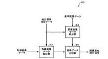
図14に、第2の構成例における画像変化検出部の機能ブロック構成例を示す。第2の構成例における画像変化検出部80は、取得画像データ抽出部82、基準画像データ抽出部84、画像データ比較部86を含む。
【0127】
取得画像データ抽出部82、基準画像データ抽出部84及び画像データ比較部86の機能は、組み合わせ回路、ASIC又はソフトウェアによる制御されるCPUによって実現される。
【0128】
取得画像データ抽出部82は、取得画像データから、比較領域の画像データを抽出する。取得画像データは、スタートアドレスSA0及びエンドアドレスEA0により指定される矩形領域を画像領域とする。比較領域は、スタートアドレスSA及びエンドアドレスEAにより指定される矩形領域である。比較領域のスタートアドレスSA及びエンドアドレスEAは、図示しないCPUによって指定される抽出領域指定データにより特定される。
【0129】
基準画像データ抽出部84は、基準画像データから、比較領域の画像データを抽出する。基準画像データは、スタートアドレスSA0及びエンドアドレスEA0により指定される矩形領域を画像領域とする。比較領域は、スタートアドレスSA及びエンドアドレスEAにより指定される矩形領域である。基準画像データ抽出部84では、上述の抽出領域指定データにより比較領域が特定される。
【0130】
画像データ比較部86は、取得画像データ抽出部82によって抽出領域指定データにより特定される比較領域の画像データと、基準画像データの画像領域のうち該比較領域に対応する領域の画像データとを比較する。そして、両画像データの例えば同一種類の色差成分について一致すると判断されたときは画像変化検出信号を出力しない。一方、該色差成分について両画像データが不一致であると判断されたときは画像変化検出信号を出力する。
【0131】
1.2.3 第3の構成例
図15(A)、(B)に、第3の構成例における画像変化検出部の動作を説明する図を示す。図15(A)は、基準画像取り込み時のイメージを示す。図15(B)は、取得画像取り込み時のイメージを示す。
【0132】
画像取込部が、ドア90を有する部屋の内部の画像を取り込むものとする。ドア90の部分の画像データは、いわゆる暗いデータである。暗いデータは、輝度の値が小さいデータである。そこで図15(A)に示すように、画像変化の検出が行われる領域の中心位置(例えば画像取込部の焦点92)を、ドア90の部分にもってくる。
【0133】
次に、図15(B)に示すようにドア90が開くと、画像変化の検出が行われる領域の中心位置の輝度が大幅に変化する。部屋の外部では、夜であっても一般的に月明かり、外灯や部屋の外の廊下の灯りがある。そのため、夜であっても画像の変化の検出精度を向上させることができる。これは、基準画像データとして暗いデータを採用したからである。
【0134】
図16に、第3の構成例における画像変化検出部の機能ブロック構成例を示す。第3の構成例における画像変化検出部100は、少なくとも画像データ比較部104を含む。取得画像データのフォーマットがRGBフォーマットの場合には、画像データフォーマット変換部102を更に含む。なお取得画像データのフォーマットが輝度成分及び第1及び第2の色差成分からなるフォーマットである場合には、画像データフォーマット変換部102を省略した構成とすることができる。
【0135】
画像データフォーマット変換部102及び画像データ比較部104の機能は、組み合わせ回路、ASIC又はソフトウェアによる制御されるCPUによって実現される。
【0136】
画像データフォーマット変換部102は、RGBフォーマットの取得画像データを、Y成分、Cb成分及びCr成分を有するフォーマットの画像データに変換する。
【0137】
そして、基準画像データとして、少なくともその輝度成分が記憶されている。基準画像データの画素の輝度成分の値を平均した平均値は、画像変化が検出されるときの取得画像データの画素の輝度成分の値を平均した平均値より小さい。ここで、平均値とは、画像データの複数の画素の輝度成分を平均したものである。
【0138】
例えば基準画像の画像領域の大半部分が、図15(A)に示すドア90のように輝度成分の値が小さい画像となるようにする。こうすることで、図15(B)に示すようにドア90が開くと、外部からの明かりによって、基準画像の輝度成分の値より大きい輝度成分を有する取得画像が得られる。
【0139】
画像データ比較部104は、基準画像データの各画素の輝度成分と、取得画像データの各画素の輝度成分とを比較する。そして、各画素について基準画像データの輝度成分の値に対する取得画像データの輝度成分の値の変化率を求め、これらの変化率の平均値が正の変化基準値(第1の基準値)以下のときには、画像変化検出信号を出力しない。一方、該変化率の平均値が上記した変化基準値を超えたときは画像変化検出信号を出力する。
【0140】
なお、画像変化検出部100が含む画像データ比較部104において、画素ごとに、取得画像データの輝度成分と基準画像データの輝度成分とを比較するようにしてもよい。この場合、画像データ比較部104は、基準画像データの輝度成分の絶対値を基準に、取得画像データの輝度成分の絶対値が変化したことを条件に、取得画像が変化したことを検出する。より具体的には、画像データ比較部104は、基準画像データの輝度成分の絶対値を基準に、取得画像データの輝度成分の絶対値が増加したことを条件に、取得画像が変化したことを検出する。
【0141】
このように基準画像として暗い画像を採用することで、画像が変化したときに明るい画像となるため、画像変化の検出精度を向上させることができる。ここで明るい画像とは、暗い画像に対してその一部又は全体の領域において輝度成分の値が大きい画像をいう。
【0142】
また基準画像として採用される暗い画像として、明度が低ければ低いほど、画像が変化したときの色差成分の変化率が大きくなる画像ということもできる。
【0143】
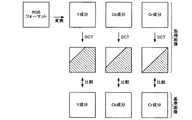
1.2.4 第4の構成例
図17に、第4の構成例における画像変化検出部の動作を説明する図を示す。第4の構成例では、基準画像及び取得画像のY成分、Cb成分及びCr成分について、離散コサイン変換(Discrete Cosine Transformation:DCT)して得られた周波数成分が用いられる。画像変化が大きいとき、DCTによって得られた周波数成分のうち高い周波数成分から低い周波数成分までが大きく変化する。これに対して、画像変化がごく僅かのとき、DCTによって得られた周波数成分のうち高い周波数成分のみが大きく変化し、低い周波数成分の変化はほとんどない。
【0144】
そこで第4の構成例では、例えば取得画像データがRGBフォーマットの場合、まず該取得画像データのRGB成分の各データを、Y成分、Cb成分及びCr成分に変換する。取得画像データのY成分についてDCTを行い、各周波数成分のデータが得られる。得られたデータのうち、所与のY成分用閾値(第1の閾値)より低い周波数成分のデータのみが抽出される。同様にして基準画像データについてもDCTにより得られた各周波数成分のデータのうち、該Y成分用閾値より低い周波数成分のデータのみが抽出される。そして、両画像データのDCTにより得られ該Y成分用閾値より低い周波数成分のデータ同士で比較する。
【0145】
同様に、両画像データのCb成分、Cr成分についても、各成分用閾値より低い周波数成分同士で比較する。
【0146】
そして、各成分の比較結果に基づいて、両画像が一致するか否かが検出される。こうすることで、画像変化の検出精度を大幅に向上させることができるようになる。またR成分、G成分及びB成分ではなく、Y成分、Cb成分及びCr成分についてDCTにより得られた周波数成分について比較を行うことで、画像の明暗を精度良く検出することができる。
【0147】
図18に、第4の構成例における画像変化検出部の機能ブロック構成例を示す。第4の構成例における画像変化検出部110は、少なくともDCT演算部112−Y、112−Cb、112−Cr、データ抽出部114−Y、114−Cb、114−Cr、画像データ比較部116を含む。画像データ比較部116は、Y成分比較部117−Y、Cb成分比較部117−Cb、Cr成分比較部117−Crを含む。取得画像データのフォーマットがRGBフォーマットの場合には、画像データフォーマット変換部118を更に含む。なお取得画像データのフォーマットが輝度成分及び色差成分からなるフォーマットである場合には、画像データフォーマット変換部118を省略した構成とすることができる。
【0148】
DCT演算部112−Y、112−Cb、112−Cr、データ抽出部114−Y、114−Cb、114−Cr、画像データ比較部116及び画像データフォーマット変換部118の各機能は、組み合わせ回路、ASIC又はソフトウェアによる制御されるCPUによって実現される。
【0149】
画像データフォーマット変換部118は、RGBフォーマットの取得画像データを、Y成分、Cb成分及びCr成分を有するフォーマットの画像データに変換する。
【0150】
DCT演算部112−Yは、画像データフォーマット変換部118によりフォーマット変換された取得画像データのY成分について、DCTを行って得られた各周波数成分のデータを出力する。
【0151】
DCT演算部112−Cbは、画像データフォーマット変換部118によりフォーマット変換された取得画像データのCb成分について、DCTを行って得られた各周波数成分のデータを出力する。
【0152】
DCT演算部112−Crは、画像データフォーマット変換部118によりフォーマット変換された取得画像データのCr成分について、DCTを行って得られた各周波数成分のデータを出力する。
【0153】
データ抽出部114−Yには、DCT演算部112−YからY成分についてDCTにより得られた各周波数成分のデータと、Y成分用閾値Y−th(第1の閾値)とが入力される。データ抽出部114−Yは、DCT演算部112−YからY成分についてDCTにより得られた各周波数成分のデータから、Y成分用閾値Y−thより低い周波数成分のデータを抽出する。
【0154】
データ抽出部114−Cbには、DCT演算部112−CbからCb成分についてDCTにより得られた各周波数成分のデータと、Cb成分用閾値Cb−th(第2の閾値)とが入力される。データ抽出部114−Cbは、DCT演算部112−CbからCb成分についてDCTにより得られた各周波数成分のデータから、Cb成分用閾値Cb−thより低い周波数成分のデータを抽出する。
【0155】
データ抽出部114−Crには、DCT演算部112−CrからCr成分についてDCTにより得られた各周波数成分のデータと、Cr成分用閾値Cr−th(第3の閾値)とが入力される。データ抽出部114−Crは、DCT演算部112−CrからCr成分についてDCTにより得られた各周波数成分のデータから、Cr成分用閾値Cr−thより低い周波数成分のデータを抽出する。
【0156】
画像データ比較部116には、基準画像データのY成分、Cb成分及びCr成分について同様に得られたデータと、データ抽出部114−Y、114−Cb、114−Crにより抽出されたデータとが入力される。基準画像データについては、そのY成分、Cb成分及びCr成分についてそれぞれDCTを行って得られた周波数成分のうち、それぞれY成分用閾値Y−th、Cb成分用閾値Cb−th及びCr成分用閾値Cr−thより低い周波数成分のデータが入力される。
【0157】
そして、各成分ごとに比較され、各成分の比較結果に基づいて、両画像が一致するか否かが判別される。
【0158】
より具体的には、画像データ比較部116において、Y成分比較部117−Y(輝度成分比較部)が、取得画像データのY成分をDCTして得られた周波数成分のうちY成分用閾値Y−th(第1の閾値)より低い周波数成分と、基準画像データのY成分をDCTして得られた周波数成分のうちY成分用閾値Y−thより低い周波数成分とを比較する。またCb成分比較部117−Cb(第1の色差成分比較部)が、取得画像データのCb成分(第1の色差成分)をDCTして得られた周波数成分のうちCb成分用閾値Cb−th(第2の閾値)より低い周波数成分と、基準画像データのCb成分をDCTして得られた周波数成分のうちCb成分用閾値Cb−thより低い周波数成分とを比較する。更にCr成分比較部117−Cr(第2の色差成分比較部)が、取得画像データのCr成分(第2の色差成分)をDCTして得られた周波数成分のうちCr成分用閾値Cr−th(第3の閾値)より低い周波数成分と、基準画像データのCr成分をDCTして得られた周波数成分のうちCr成分用閾値Cr−thより低い周波数成分とを比較する。そして、画像データ比較部116は、Y成分比較部117−Y、Cb成分比較部117−Cb及びCr成分比較部117−Crの各比較結果に基づいて、基準画像を基準として取得画像が変化したことを示す画像変化検出信号を出力する。
【0159】
画像データ比較部116は、例えば各比較部の比較結果が全て一致のときに両画像が一致すると判断して画像変化検出信号を出力しない。一方、画像データ比較部116は、例えば各比較部の比較結果のいずれか1つが不一致のときに両画像が不一致であると判断して画像変化検出信号を出力する。また画像データ比較部116は、各比較部の比較結果を多数決して両画像の一致を判別するようにしてもよい。或いは、画像データ比較部116は、各比較部の比較結果をそれぞれ重み付けして両画像の一致を判別するようにしてもよい。
【0160】
2. 第2の実施形態
第1の実施形態では、画像変化が検出されるとその変化後の画像を画像閲覧装置に対して送信していたが、これに限定されるものではない。
【0161】
図19に、第2の実施形態における画像通信システムのブロック図を示す。画像通信システム200は、所与のネットワーク(通信網)202を介して互いに接続される画像処理装置210と、画像閲覧装置230とを含む。
【0162】
画像処理装置210は、取り込んだ画像を取得画像データとしてネットワーク202を介して送信すると共に、該画像が基準画像を基準として変化したことを検出して、取り込んだ画像が変化したことを示す画像変化検出フラグをネットワーク202を介して送信する。画像処理装置210は、例えば取得画像データと画像変化検出フラグとを含む送信パケットをネットワーク202を介して送信することができる。
【0163】
画像変化検出フラグは、第1の実施形態における画像変化検出部と同様にして生成される。
【0164】
画像閲覧装置230では、ネットワーク202上のパケットを監視する。より具体的には、画像処理装置210からの送信パケットを取り込んで、画像変化検出フラグにより画像が変化したことが通知されたとき、該送信パケットに含まれる取得画像データを取り出して、表示出力等を行うことができる。
【0165】
これにより、画像処理装置210によるパケットの生成と、画像閲覧装置230によるパケットの監視という非常に簡素な構成と制御で低コスト化を図ることができ、かつ画像閲覧装置230において画像変化を確実に把握することができる。
【0166】
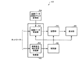
図20に、第2の実施形態における画像処理装置210の機能ブロック図を示す。ここで図2に示す画像処理装置20と同一部分には同一符号を付し、適宜説明を省略する。
【0167】
画像処理装置210は、画像取込部22、第1の記憶部24、画像変化検出部212、送信データ生成部214、送信部216を含む。
【0168】
画像変化検出部212は、上述の画像変化検出部26、62と同様の機能を有する。画像変化検出部212は、基準画像を基準として、取得画像が変化したことを示す画像変化検出フラグを出力することができる。例えば画像変化検出フラグが「1」のとき取得画像が変化したことが検出されたことを示し、画像変化検出フラグが「0」のとき取得画像が変化したことが検出されなかったことを示す。
【0169】
送信データ生成部214は、画像取込部22によって取り込まれた取得画像データと、画像変化検出部212からの画像変化検出フラグとを含む送信データ(広義には通信データ)を生成する。
【0170】
図21に、送信データの構成例を示す。送信データは、所定のフォーマットを有する。例えば送信データは、少なくともヘッダ情報が設定されるヘッダフィールドと、取得画像データが設定されるデータフィールドとを含んで構成される。また送信データは、ヘッダ情報及び取得画像データ等が設定されない空きフィールド(空き領域)を有する。
【0171】
ヘッダ情報は、送信データの送信先、送信元といった通信制御情報である。空きフィールドには、画像変化検出フラグが設定される。
【0172】
送信データは、固定長のデータであってもよいし、可変長のデータであってもよい。送信データの各フィールドの情報(少なくとも取得画像データ、画像変化検出フラグ)が、送信側と受信側とで共通して認識されていればよい。送信データ生成部214は、図21に示す構成の送信パケットを生成する。
【0173】
図20において、送信部216は、送信データ生成部214により生成された送信パケットをネットワークを介して送信する。
【0174】
送信データ生成部214の機能は、ASICや、CPUなどのハードウェアをファームウェアやソフトウェア等により制御することで実現される。送信部216の機能は、ASICや通信用ICなどのハードウェアをファームウェアやソフトウェア等により制御することで実現される。
【0175】
このような画像処理装置210は、CPU(図示せず)及びメモリ(図示せず)を有する。そして画像処理装置210では、メモリに記憶されたプログラムにしたがってCPUにより、以下に示す制御が行われる。
【0176】
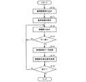
図22に、第2の実施形態における画像処理装置の制御フローの一例を示す。
【0177】
画像処理装置210では、まず画像取込部22によって基準画像の取り込みが行われる(ステップS100)。取り込まれた基準画像は、第1の記憶部24に保存される(ステップS101)。
【0178】
これ以降、画像処理装置210では、画像取込部22により、周期的に画像の取り込みが行われる。まず、画像取込部22によって、新たに画像が取得画像として取り込まれる(ステップS102)。取得画像は、第1の記憶部24に保存された基準画像と比較され、画像変化検出部212が画像変化検出フラグが生成する(ステップS103)。
【0179】
そして、送信データ生成部214により、取得画像データと画像変化検出フラグとが設定された送信パケットが生成される(ステップS104)。
【0180】
処理が終了のとき(ステップS105:Y)一連の処理を終了するが(エンド)、処理が終了ではないとき(ステップS105:N)、ステップS102に戻る。
【0181】
このような画像処理装置210では、周期的に取り込まれた取得画像の画像データと、取得画像が基準画像を基準として変化したことが検出されたことを示す画像変化検出フラグとが設定された送信データが生成される。そして、該送信データがネットワークを介して送信される。こうすることで、画像処理装置210では、画像変化検出の有無に応じて処理フローを変える必要がないため、画像処理装置210の構成及び制御の簡素化を図ることができる。また画像閲覧装置230では、ネットワーク上に画像処理装置210からの送信データを監視するのみで、変化後の画像を取得することができる。
【0182】
図23に、第2の実施形態における画像閲覧装置230の機能ブロック図を示す。ここで、画像閲覧装置230が図5に示す画像閲覧装置40と同一部分には同一符号を付し、適宜説明を省略する。
【0183】
画像閲覧装置230は、受信部232、解析部234、抽出部236、記憶部44、表示部46、制御部238を含む。
【0184】
受信部232は、画像処理装置210により、ネットワーク202を介して送信された通信データを受信する。通信データには、画像処理装置210において取り込まれた取得画像のデータである取得画像データと、基準画像を基準として取得画像が変化したことを示す画像変化検出フラグとが含まれる。受信部232の機能は、ASICや通信用ICなどのハードウェアをファームウェアやソフトウェア等により制御することで実現される。
【0185】
解析部234は、受信部232によって受信された通信データに含まれる画像変化検出フラグに基づいて、取得画像が変化したか否かを解析する。受信された通信データに含まれる画像変化検出フラグが「1」のとき、解析部234は、例えば基準画像を基準として、取得画像が変化したことが検出されたと判別することができる。また受信された通信データに含まれる画像変化検出フラグが「0」のとき、解析部234は、例えば基準画像を基準として、取得画像が変化したことが検出されなかったと判別することができる。
【0186】
抽出部236は、解析部234によって取得画像が変化したことが検出されたとき、通信データに含まれる取得画像データを抽出する。
【0187】
このような解析部234及び抽出部236の機能は、ソフトウェア又はファームウェアにより制御されるCPUにより実現される。
【0188】
抽出部236によって抽出された取得画像データは、記憶部44に格納される。
【0189】
制御部238は、受信部232、解析部234、抽出部236、記憶部44、表示部46の制御を司る。制御部238は、CPU、RAM又はROMを有する。RAM又はROMに記憶されたプログラムにしたがって処理を行ったCPUが、受信部232、解析部234、抽出部236、記憶部44、表示部46を制御することができる。
【0190】
図24に、画像閲覧装置230の制御部238の処理フローの一例を示す。制御部238は、まず受信部232により、画像処理装置210から送信される通信データの受信を監視する(ステップS120)。すなわち、受信部232では、通信データが受信されるまでステップS120を繰り返す(ステップS120:N)。
【0191】
受信部232において画像処理装置210からの通信データが受信されたとき(ステップS120:Y)、制御部238は、解析部234により通信データに含まれる画像変化検出フラグを参照して、取得画像が変化したことが検出されたか否かを判別する(ステップS121)。
【0192】
その結果、取得画像の変化が検出されたと判別されたとき(ステップS122:Y)、制御部238は、抽出部236により、当該通信データに含まれる取得画像データを抽出させる(ステップS123)。
【0193】
続いて制御部238は、抽出部236二より抽出された取得画像データを記憶部44に保存する(ステップS124)。続いて制御部238は、記憶部44に保存された画像データを表示部46に供給する(ステップS125)。表示部46は、供給された画像データに基づく表示出力を行う。
【0194】
処理が終了のとき(ステップS126:Y)一連の処理を終了するが(エンド)、処理が終了ではないとき(ステップS126:N)、ステップS120に戻る。なおステップS122で、取得画像の変化が検出されなかったことが判別されたとき(ステップS122:N)、ステップS120に戻る。
【0195】
このように画像閲覧装置230は、取得画像データと画像変化検出フラグとを含む通信データを監視して、画像変化が検出されたときに当該通信データに含まれる取得画像データを取り出して表示出力することができる。したがって、画像閲覧装置230では、変化した画像データの取得を行うための構成及び制御を簡素化することができる。
【0196】
第2の実施形態における画像処理装置210においても、第1の実施形態の第1の変形例と同様に、基準画像を周期的に更新させることができる。
【0197】
また第2の実施形態における画像処理装置210においても、第1の実施形態の第2の変形例と同様に、赤外線による画像の取得を行うようにすることができる。
【0198】
なお、本発明は上述した実施の形態に限定されるものではなく、本発明の要旨の範囲内で種々の変形実施が可能である。
【0199】
第1及び第2の実施形態における画像通信システムでは、防犯用途に用いることができるが、これに限定されるものではない。ネットワークを介して画像の取り込みを行う画像処理装置と、該画像処理装置により取り込まれた画像を表示出力する画像閲覧装置とを含むシステムに適用可能である。
【0200】
なお上記した画像通信システムの画像閲覧装置では、受信した画像データを記憶部に一旦格納しているが、そのまま表示部に供給して画像データに基づく表示出力を行うようにすることも可能である。
【0201】
また上述の実施形態では、画像として静止画や動画を送信することも考えられる。
【0202】
更に上述の実施形態では、Y成分、Cb成分及びCr成分からなる画像のフォーマットについて述べたが、これに限定されるものではない。画像フォーマットが、Y成分、Cb成分及びCr成分から求められる別フォーマットであってもよい。
【0203】
また、本発明のうち従属請求項に係る発明においては、従属先の請求項の構成要件の一部を省略する構成とすることもできる。また、本発明の1の独立請求項に係る発明の要部を、他の独立請求項に従属させることもできる。
【図面の簡単な説明】
【図1】第1の実施形態における画像通信システムの構成ブロック図。
【図2】第1の実施形態における画像処理装置の機能ブロック図。
【図3】第1の実施形態における画像処理装置の動作例を示すフロー図。
【図4】画像処理装置の具体的構成例を示すブロック図。
【図5】画像閲覧装置の機能ブロック図。
【図6】画像閲覧装置の制御部の処理例を示すフロー図。
【図7】第1の変形例における画像処理装置の機能ブロック図。
【図8】第1の変形例における画像処理装置の動作例を示すフロー図。
【図9】第2の変形例における画像処理装置の機能ブロック図。
【図10】第2の変形例における画像処理装置の動作例を示すフロー図。
【図11】第1の構成例における画像変化検出部の動作説明図。
【図12】第1の構成例における画像変化検出部の機能ブロック図。
【図13】第2の構成例における画像変化検出部の動作説明図。
【図14】第2の構成例における画像変化検出部の機能ブロック図。
【図15】図15(A)、(B)は、第3の構成例における画像変化検出部の動作説明図。
【図16】第3の構成例における画像変化検出部の機能ブロック図。
【図17】第4の構成例における画像変化検出部の動作説明図。
【図18】第4の構成例における画像変化検出部の機能ブロック図。
【図19】第2の実施形態における画像通信システムのブロック図。
【図20】第2の実施形態における画像処理装置の機能ブロック図。
【図21】第2の実施形態における送信データの構成例を示す説明図。
【図22】第2の実施形態における画像処理装置の処理例を示すフロー図。
【図23】第2の実施形態における画像閲覧装置の機能ブロック図。
【図24】画像閲覧装置の制御部の処理例を示すフロー図。
【符号の説明】
10、200 画像通信システム、 12、202 ネットワーク、
20、60、72、210 画像処理装置、 22、72 画像取込部、
24 第1の記憶部、 26、62、75、80、100、110、
212 画像変化検出部、 27、216 送信部、 28 画像データ送信部、 29 画像変化検出信号送信部、 31 カメラ、 32 RAM、 34CPU、 35 RTC、 36 センサ、 37 不揮発性メモリ、 40、230 画像閲覧装置、 42、232 受信部、 44 記憶部、 46 表示部、 48、238 制御部、 50 画像変化検出信号受信部、 52 画像データ受信部、 54 画像データ送信元アドレス記憶部、 73 赤外線撮像デバイス、 74 モード設定部、 76、102、118 画像データフォーマット変換部、 77、86、104、116 画像データ比較部、 82取得画像データ抽出部、 84 基準画像データ抽出部、 112−Y、112−Cb、 112−Cr DCT演算部、 114−Y、114−Cb、114−Cr データ抽出部、 117−Y Y成分比較部、 117−Cb Cb成分比較部、 117−Cr Cr成分比較部、 214 送信データ生成部、234 解析部、 236 抽出部[0001]
TECHNICAL FIELD OF THE INVENTION
The present invention relates to an image processing device, an image browsing device, and an image communication system.
[0002]
[Prior art]
There is an image communication system that transmits and receives image data via a communication network. In an image communication system, images captured at a remote location can be viewed. Such image communication systems are widely used, for example, for security systems.
[0003]
In a security system, an image of a place to be monitored is captured by a monitoring camera, and the captured image is transmitted to a monitoring device. The monitoring device receives an image from the monitoring camera and performs display output. Thus, the observer who sees the displayed and output image can grasp the change in the state of the place to be monitored.
[0004]
A so-called Web camera can be used as such a monitoring camera. A Web camera is a camera connected to the Internet as a computer network. The image captured by the Web camera is sent to a display device that is watched by a supervisor at a position far away from the Web camera.
[0005]
[Patent Document 1]
JP-A-11-72348
[0006]
[Problems to be solved by the invention]
However, on the monitoring side, the image received from the monitoring camera is displayed and output. Therefore, the display device on the monitoring side must always be started up. Also, it is necessary for the observer to watch the display device for the image captured by the monitoring camera. Therefore, the concentration of the observer is reduced due to fatigue or the like, and a change in the state of the place to be monitored may be overlooked, and the purpose of crime prevention may not be achieved.
[0007]
In such an image communication system, it is desirable that the viewer can reliably grasp the image change at a remote place.
[0008]
The present invention has been made in view of the above technical problems, and an object of the present invention is to provide an image processing apparatus, an image browsing apparatus, and an image communication apparatus capable of reliably recognizing a change in a captured image. It is to provide a system.
[0009]
[Means for Solving the Problems]
In order to solve the above-described problems, the present invention is an image processing apparatus connected to a communication network, comprising: an image capturing unit that periodically captures an image; and a second image processing unit that stores reference image data that is image data of the reference image. 1, comparing the acquired image data, which is the image data of the acquired image captured by the image capturing unit, with the reference image data, and determining whether the obtained image has changed with respect to the reference image. An image change detecting unit for detecting whether the acquired image data has been changed by the image change transmitting unit, and an image data transmitting unit for transmitting the acquired image data via the communication network. An image change detection signal transmitting unit that transmits an image change detection signal indicating that the acquired image has changed through the communication network or another communication network different from the communication network. To.
[0010]
According to the present invention, the acquired image data is transmitted via the communication network, and the image change detection signal is transmitted via the communication network or another communication network different from the communication network. The side does not need to constantly monitor the presence or absence of a change in the captured image, and can display and output the image after receiving a notification that the image has changed by the image change detection signal. Therefore, it is possible to provide an image processing apparatus that reduces the burden of monitoring images received via a communication network and reduces communication traffic.
[0011]
The present invention is also an image processing device connected to a communication network, wherein the image capturing unit periodically captures an image, a first storage unit that stores reference image data that is image data of the reference image, An image change that compares the acquired image data, which is the image data of the acquired image acquired by the image acquisition unit, with the reference image data, and detects whether the acquired image has changed based on the reference image. A detection unit, an image change detection flag indicating that the image change has been detected by the image change detection unit, and a transmission data generation unit that generates transmission data including the obtained image data; An image data transmitting unit that transmits data via the communication network.
[0012]
In the present invention, transmission data is generated in which acquired image data taken in periodically and an image change detection flag indicating that the acquired image has been changed with reference to the reference image are set. Then, the transmission data is transmitted via the communication network. By doing so, the image processing apparatus does not need to change the processing according to the presence or absence of the image change detection, so that the configuration and control of the image processing apparatus can be simplified. Further, on the receiving side of the transmission data, the image after the change can be obtained only by monitoring the transmission data from the image processing apparatus. Therefore, an image processing apparatus that simplifies the configuration and control of the receiving side is provided. Can be.
[0013]
In the image processing apparatus according to the present invention, the acquired image data may be set in a predetermined data field of the transmission data, and the image change detection flag may be set in an empty field of the transmission data.
[0014]
In the present invention, since the image change detection flag is set in the empty field of the transmission data, it is possible to apply the existing image data to the communication system.
[0015]
Further, in the image processing apparatus according to the present invention, the acquired image data captured by the image capturing unit is converted to the reference image on the condition that the captured image has not been changed by the image change detection unit. The data can be stored in the first storage unit.
[0016]
ADVANTAGE OF THE INVENTION According to this invention, the fall of the detection accuracy of an image change can be minimized with respect to the change of the environment of the place which takes in an image.
[0017]
The image processing apparatus according to the present invention further includes a mode setting unit for setting a normal mode or an infrared mode, wherein the image capturing unit has an infrared imaging device, and the infrared mode is set by the mode setting unit. In this state, the first storage unit stores, as reference image data, image data of a first infrared image generated by detecting infrared rays by the infrared imaging device, and the image change detection unit Comparing the image data of the second infrared image as the acquired image captured by the infrared imaging device with the image data of the first infrared image to determine whether the acquired image has changed with respect to the reference image. The image data transmitting unit transmits the image data of the second infrared image as the acquired image data, and the image change detection signal transmitting unit It can transmit the image change detection signal indicating that the acquired image is changed.
[0018]
ADVANTAGE OF THE INVENTION According to this invention, the fall of the detection accuracy of an image change with respect to the change of the brightness of an imaging environment can be suppressed.
[0019]
Further, in the image processing apparatus according to the present invention, when the pixels of the acquired image data and the reference image data include a luminance component and first and second color difference components, the image change detection unit may include the acquired image data. A first color difference component of the reference image data and a first color difference component of the reference image data. The image data comparison unit includes a first color difference component of the acquired image data and the first color difference component of the reference image data. When it is determined that the components are different, it can be detected that the acquired image has changed.
[0020]
According to the present invention, it is possible to reduce the data amount and the processing load by comparing only one color difference component. For example, when only the Cb component of the reference image data and the acquired image data are compared, it is possible to accurately detect a change in an image captured in a dark shooting environment.
[0021]
Further, in the image processing device according to the present invention, the image change detection unit, the obtained image data extraction unit that extracts the image data of the comparison area of the obtained image data, and the image data extracted by the obtained image data extraction unit An image data comparison unit that compares image data of an area corresponding to the comparison area in the image area of the reference image data, wherein the image data comparison unit includes an image extracted by the acquired image data extraction unit. When it is determined that the data is different from the image data of the area corresponding to the comparison area in the image area of the reference image data, it can be detected that the acquired image has changed.
[0022]
ADVANTAGE OF THE INVENTION According to this invention, since the area | region compared with an image area | region is made small, reduction of the data amount accompanying the detection of an image change and reduction of a processing load can be achieved.
Further, in the image processing device according to the present invention, the average value obtained by averaging the luminance component values of the pixels of the reference image data is an average value obtained by averaging the luminance component values of the pixels of the acquired image data when an image change is detected. Smaller than the value, the image change detection unit includes a luminance component of the acquired image data and an image data comparison unit that compares a luminance component of the reference image data, and the image data comparison unit includes A change in the acquired image can be detected based on a luminance component and a luminance component of the reference image data.
[0023]
Further, in the image processing device according to the present invention, the image data comparing unit may determine a first reference value having a positive average value obtained by averaging a change rate of a luminance component value of a pixel of the acquired image data with respect to the reference image data. If it exceeds, it can be detected that the acquired image has changed.
[0024]
Further, in the image processing apparatus according to the present invention, the image change detection unit includes, for each pixel, an image data comparison unit that compares a luminance component of the acquired image data with a luminance component of the reference image data, The comparison unit can detect that the acquired image has changed on condition that the absolute value of the luminance component of the acquired image data has changed with reference to the absolute value of the luminance component of the reference image data.
[0025]
Further, in the image processing device according to the present invention, the image data comparing unit is based on an absolute value of a luminance component of the reference image data, on the condition that an absolute value of a luminance component of the acquired image data increases. It is possible to detect that the acquired image has changed.
[0026]
In the present invention, a so-called dark image is adopted as the reference image. Therefore, a bright image is obtained when the image changes, so that the detection accuracy of the image change can be improved.
[0027]
Further, in the image processing apparatus according to the present invention, when the pixels of the acquired image data and the reference image data include a luminance component and first and second color difference components, the image change detection unit may include the acquired image data. Among the frequency components obtained by performing a discrete cosine transform of the luminance component, and the first component among the frequency components obtained by performing a discrete cosine transform of the luminance component of the reference image data. A luminance component comparison unit that compares a frequency component lower than a threshold, a frequency component lower than a second threshold among frequency components obtained by performing a discrete cosine transform of the first color difference component of the acquired image data, A first color difference component comparison unit that compares a frequency component obtained by performing a discrete cosine transform of the first color difference component of the image data with a frequency component lower than the second threshold value; Data components obtained by performing discrete cosine transform on the frequency components lower than a third threshold value among the frequency components obtained by performing discrete cosine transform on the second color difference component of the data and the second color difference component of the reference image data. A second chrominance component comparison unit for comparing a frequency component lower than the third threshold value among the frequency components, wherein the image data comparison unit compares the first chrominance component with the comparison result of the luminance component comparison unit. A change in the acquired image can be detected based on the comparison result of the comparison unit and the comparison result of the second color difference component comparison unit.
[0028]
According to the present invention, only the low frequency component among the obtained frequency components is used, so that only the image change when the image change is large can be detected, and the detection error can be reduced.
[0029]
The present invention is also directed to an image browsing apparatus connected to a communication network, wherein the captured image obtained through the communication network receives an image change detection signal indicating that the captured image has changed with reference to the reference image. A detection signal receiving unit, and an image obtained by capturing the acquired image in the communication network or another communication network different from the communication network, provided that the image change detection signal is received by the image change detection signal receiving unit. An image data receiving unit that establishes a communication path with the processing device and receives image data from the image processing device; and an image browsing device that includes a storage unit that stores the image data received by the image data receiving unit. Involved.
[0030]
The image browsing device according to the present invention includes an image data transmission source address information storage unit that stores address information associated with the image processing device in the communication network or another communication network different from the communication network, The image data receiving unit can establish a communication path with the image processing device using the address information stored in the image data transmission source address information storage unit.
[0031]
Further, in the image browsing device according to the present invention, in the communication network or another communication network different from the communication network, the address information associated with the image processing device is different from the communication network or another communication different from the communication network. Acquired via a network, the image data receiving unit can establish a communication path with the image processing apparatus using the address information.
[0032]
According to the present invention, on the condition that the image change detection signal is received, a communication connection can be made with the transmission source of the image data, and the captured image data can be received. Therefore, the monitoring load of the present apparatus can be greatly reduced, and the state of the captured image after the change can be reliably grasped.
[0033]
The present invention also relates to an image browsing apparatus connected to a communication network, wherein the acquired image data is data of an acquired image, and an image change detection flag indicating that the acquired image has changed with reference to a reference image. And a receiving unit that receives communication data including the communication data via the communication network, and based on the image change detection flag included in the communication data received by the receiving unit, whether a change in the acquired image is detected. An analysis unit that analyzes the extracted image data included in the communication data when the analysis unit detects that a change in the acquired image has been detected, and an extraction unit that extracts the acquired image data included in the communication data. And a storage unit for storing the acquired image data.
[0034]
According to the present invention, communication data including acquired image data and an image change detection flag can be monitored, and when an image change is detected, the acquired image data included in the communication data can be extracted and displayed and output. . Therefore, in the present apparatus, the configuration and control for acquiring the changed image data can be simplified.
[0035]
Further, the present invention is an image communication system for communicating image data via a communication network, including the image processing device described above and the image browsing device according to any one of the above, wherein the image browsing device is The present invention relates to an image communication system that captures acquired image data transmitted by the image processing device based on the image change detection signal transmitted by the image processing device via a communication network.
[0036]
According to another aspect of the present invention, there is provided an image communication system for communicating image data via a communication network, the image communication device including the image processing device described above and the image browsing device described above, wherein the image browsing device includes the communication network Via the image processing apparatus, based on the image change detection flag from the image processing apparatus.
[0037]
Further, in the image communication system according to the present invention, the acquired image data captured by the image capturing unit is converted to the reference image on the condition that the captured image is not changed by the image change detection unit. The data can be stored in the first storage unit.
[0038]
Further, in the image communication system according to the present invention, the image processing device further includes a mode setting unit for setting a normal mode or an infrared mode, the image capturing unit includes an infrared imaging device, In a state where the infrared mode is set by the unit, the first storage unit stores, as reference image data, image data of a first infrared image generated by detecting infrared light by the infrared imaging device, The image change detection unit compares image data of a second infrared image and image data of the first infrared image as an acquired image captured by the infrared imaging device, and obtains an acquired image based on a reference image. The image data transmitting unit transmits the image data of the second infrared image as the acquired image data, and detects whether the Image change detection signal transmitting unit can transmit the image change detection signal indicating that the acquired image is changed.
[0039]
Further, in the image communication system according to the present invention, when the pixels of the acquired image data and the reference image data include a luminance component and first and second color difference components, the image change detection unit includes the acquired image data. A first color difference component of the reference image data and a first color difference component of the reference image data. The image data comparison unit includes a first color difference component of the acquired image data and the first color difference component of the reference image data. When it is determined that the components are different, it can be detected that the acquired image has changed.
[0040]
Further, in the image communication system according to the present invention, the image change detection unit is an acquisition image data extraction unit that extracts image data of a comparison region of the acquisition image data, and the image data extracted by the acquisition image data extraction unit. An image data comparison unit that compares image data of an area corresponding to the comparison area in the image area of the reference image data, wherein the image data comparison unit includes an image extracted by the acquired image data extraction unit. When it is determined that the data is different from the image data of the area corresponding to the comparison area in the image area of the reference image data, it can be detected that the acquired image has changed.
[0041]
Further, in the image communication system according to the present invention, the average value obtained by averaging the luminance component values of the pixels of the reference image data is an average value obtained by averaging the luminance component values of the pixels of the acquired image data when an image change is detected. Smaller than the value, the image change detection unit includes a luminance component of the acquired image data and an image data comparison unit that compares a luminance component of the reference image data, and the image data comparison unit includes A change in the acquired image can be detected based on a luminance component and a luminance component of the reference image data.
[0042]
Further, in the image communication system according to the present invention, the image data comparing unit may calculate a first reference value having a positive average value obtained by averaging a change rate of a luminance component value of a pixel of the acquired image data with respect to the reference image data. If it exceeds, it can be detected that the acquired image has changed.
[0043]
Further, in the image communication system according to the present invention, when the pixels of the acquired image data and the reference image data include a luminance component and first and second color difference components, the image change detection unit includes the acquired image data. Among the frequency components obtained by performing a discrete cosine transform of the luminance component, and the first component among the frequency components obtained by performing a discrete cosine transform of the luminance component of the reference image data. A luminance component comparison unit that compares a frequency component lower than a threshold, a frequency component lower than a second threshold among frequency components obtained by performing a discrete cosine transform of the first color difference component of the acquired image data, A first color difference component comparison unit that compares a frequency component obtained by performing a discrete cosine transform on a first color difference component of the image data with a frequency component lower than the second threshold value; Among the frequency components obtained by performing discrete cosine transform on the second color difference component of the image data, the frequency component lower than the third threshold value and the second color difference component of the reference image data are obtained by performing discrete cosine transform. A second chrominance component comparison unit for comparing a frequency component lower than the third threshold value among the frequency components, wherein the image data comparison unit compares the first chrominance component with the comparison result of the luminance component comparison unit. A change in the acquired image can be detected based on the comparison result of the comparison unit and the comparison result of the second color difference component comparison unit.
[0044]
BEST MODE FOR CARRYING OUT THE INVENTION
Hereinafter, preferred embodiments of the present invention will be described in detail with reference to the drawings. The embodiments described below do not unduly limit the contents of the invention described in the claims. In addition, all of the configurations described below are not necessarily essential components of the invention.
[0045]
1. First embodiment
FIG. 1 shows a block diagram of an image communication system according to the first embodiment. The
[0046]
The
[0047]
When the
[0048]
FIG. 2 shows a functional block diagram of the
[0049]
The
[0050]
The
[0051]
The image
[0052]
The
[0053]
Such an
[0054]
FIG. 3 shows an example of an operation flow of the image processing apparatus according to the first embodiment.
[0055]
In the
[0056]
Thereafter, in the
[0057]
The acquired image is compared with the reference image stored in the first storage unit 24 (Step S13). That is, by comparing the acquired image data that is the image data of the acquired image with the reference image data that is the image data of the reference image, it is detected whether the two images match.
[0058]
When it is determined that the two images do not match (step S13: Y), the image data of the acquired image (acquired image data) is transmitted from the image
[0059]
When the process is completed (step S16: Y), a series of processes is completed (end), but when the process is not completed (step S16: N), the process returns to step S12. In step S13, when it is determined that the two images do not match (step S13: N), the process similarly returns to step S12.
[0060]
The
[0061]
FIG. 4 is a block diagram illustrating a specific configuration example of the
[0062]
The
[0063]
The
[0064]
The image data of the acquired image stored in the
[0065]
As described above, the
[0066]
FIG. 5 shows a functional block diagram of the
[0067]
Further, in order to obtain image data transmitted by the
[0068]
The image change detection
[0069]
The image
[0070]
The functions of the receiving
[0071]
The
[0072]
The
(Display).
[0073]
The
[0074]
FIG. 6 shows an example of a processing flow of the
[0075]
When the image change detection signal is received (step S20: Y), the image
[0076]
Thereafter, the
[0077]
Subsequently, when image data is received by the image data receiving unit 52 (Step S25: Y), the process returns to Step S22. On the other hand, in step S25, when the image
[0078]
When the process is completed (step S27: Y), a series of processes is completed (end), but when the process is not completed (step S27: N), the process returns to step S20.
[0079]
As described above, the
[0080]
1.1 Modifications
1.1.1 First Modified Example
The reference image data stored in the first storage unit may be updated after a given period. The image processing device according to the first modification can update the reference image data stored in the first storage unit.
[0081]
FIG. 7 shows a functional block diagram of an image processing apparatus according to the first modification. Here, the same parts as those of the
[0082]
The
[0083]
In the
[0084]
Thus, even when the brightness of the place where the image is captured by the
[0085]
The
[0086]
FIG. 8 shows an example of an operation flow of the
[0087]
Thereafter, in the
[0088]
The acquired image is compared with the reference image stored in the first storage unit 24 (Step S33). That is, by comparing the acquired image data that is the image data of the acquired image with the reference image data that is the image data of the reference image, it is detected whether the two images match.
[0089]
When it is determined that the two images do not match (step S33: Y), the image data of the acquired image is transmitted by the image
[0090]
When the process is completed (step S36: Y), a series of processes is completed (end), but when the process is not completed (step S36: N), the process returns to step S32.
[0091]
When it is determined in step S33 that the two images do not match (step S33: N), the acquired image data is stored in the first storage unit 24 (step S37), and the process returns to step S32. That is, in the
[0092]
By updating the reference image at a given cycle, such an
[0093]
1.1.2 Second Modification
Further, an infrared imaging device may be provided in the image capturing unit, and a change in the image may be detected by an infrared image generated by detecting the infrared by performing on / off control of the function of the infrared imaging device. The image processing apparatus according to the second modification can detect a change in an infrared image captured by an infrared imaging device in addition to the above-described detection of an image change.
[0094]
FIG. 9 shows a functional block diagram of an image processing apparatus according to the second modification. Here, the same parts as those of the
[0095]
An
[0096]
The function of the
[0097]
In the infrared mode, the
[0098]
In the normal mode, the
[0099]
The
[0100]
FIG. 10 shows an example of an operation flowchart of the image processing apparatus according to the second modification. First, it is determined whether or not the shooting environment by the
[0101]
When it is determined that the shooting environment is bright (step S40: Y), the
[0102]
After being stored in the
[0103]
Thereafter, in the
[0104]
The acquired image is compared with the reference image stored in the first storage unit 24 (Step S45). That is, by comparing the acquired image data that is the image data of the acquired image with the reference image data that is the image data of the reference image, it is detected whether the two images match.
[0105]
When it is determined that the two images do not match (step S45: Y), the image data of the acquired image is transmitted by the image
[0106]
When the process is completed (step S48: Y), a series of processes is completed (end), but when the process is not completed (step S48: N), the process returns to step S44. When it is determined in step S45 that the two images do not match (step S45: N), the process returns to step S44.
[0107]
On the other hand, when it is determined in step S40 that the shooting environment is not bright (step S40: N), the
[0108]
After being stored in the
[0109]
Thereafter, in the
[0110]
The acquired image data of the captured infrared image is compared with the reference image stored in the first storage unit 24 (Step S55).
[0111]
When it is determined that the two images do not match (step S55: Y), the infrared image captured as the acquired image is transmitted via the network (step S56). Further, an image change detection signal indicating that the acquired image has changed is transmitted via the
[0112]
When the process ends (step S58: Y), a series of processes ends (end), but when the process does not end (step S58: N), the process returns to step S53. When it is determined in step S55 that the two images do not match (step S55: N), the process returns to step S53.
[0113]
Note that the
[0114]
Such an
[0115]
1.2 Configuration of Image Change Detection Unit
Next, a configuration example of the image
[0116]
1.2.1 First Configuration Example
FIG. 11 is a diagram illustrating the operation of the image change detection unit in the first configuration example. Here, a description will be given assuming that the image data acquired from the image capturing unit is in the RGB format, but the present invention is not limited to this. In image data in the RGB format, each pixel is represented by an RGB primary color signal.
[0117]
In the first configuration example, the acquired image data in the RGB format is converted into image data including a Y component (luminance component), a Cb component, and a Cr component. Then, the image change detection unit compares the Cb component of the acquired image data with the Cb component of the reference image data. Alternatively, the image change detection unit compares the Cr component of the acquired image data with the Cb component of the reference image data. When the Cb component is used as the first color difference component, the Cr component can be called the second color difference component. When the Cb component is used as the second color difference component, the Cr component can be called the first color difference component.
[0118]
Thus, by comparing only one color difference component, it is possible to reduce the data amount and the processing load. When the configuration is such that only the Cb component of the reference image data and the acquired image data is compared, it is possible to accurately detect a change in an image captured in a dark shooting environment.
[0119]
FIG. 12 shows a functional block configuration example of the image change detection unit in the first configuration example. The image
[0120]
The functions of the image data
[0121]
The image
[0122]
The image
[0123]
1.2.2 Second configuration example
FIG. 13 is a diagram illustrating the operation of the image change detection unit in the second configuration example. In the second configuration example, a part of the acquired image is set as a comparison area, and image data in the comparison area of the acquired image is compared with image data of an area corresponding to the comparison area in the image area of the reference image data. You.
[0124]
It is assumed that the image area of the acquired image data is a rectangular area represented by a start address SA0 and an end address EA0. In the second configuration example, image data of a rectangular extraction area represented by a start address SA and an end address EA is extracted. Then, the two image data are compared with the extracted area as a comparison area.
[0125]
As described above, by reducing the area to be compared with the image area, it is possible to reduce the data amount and the processing load.
[0126]
FIG. 14 illustrates a functional block configuration example of the image change detection unit in the second configuration example. The image
[0127]
The functions of the acquired image
[0128]
The acquired image
[0129]
The reference image
[0130]
The image
[0131]
1.2.3 Third configuration example
FIGS. 15A and 15B are diagrams illustrating the operation of the image change detection unit in the third configuration example. FIG. 15A shows an image at the time of capturing the reference image. FIG. 15B shows an image at the time of capturing an acquired image.
[0132]
It is assumed that the image capturing unit captures an image inside the room having the
[0133]
Next, when the
[0134]
FIG. 16 shows a functional block configuration example of the image change detection unit in the third configuration example. The image
[0135]
The functions of the image data
[0136]
The image data
[0137]
At least the luminance component is stored as reference image data. The average value obtained by averaging the luminance component values of the pixels of the reference image data is smaller than the average value obtained by averaging the luminance component values of the pixels of the acquired image data when an image change is detected. Here, the average value is obtained by averaging the luminance components of a plurality of pixels of the image data.
[0138]
For example, most of the image area of the reference image is an image having a small luminance component value, such as a
[0139]
The image
[0140]
The image
[0141]
By employing a dark image as the reference image in this way, a bright image is obtained when the image changes, so that the detection accuracy of the image change can be improved. Here, the bright image refers to an image in which the value of the luminance component is larger in a part or the whole of the dark image.
[0142]
Also, it can be said that as a dark image used as a reference image, the lower the brightness, the larger the change rate of the color difference component when the image changes.
[0143]
1.2.4 Fourth configuration example
FIG. 17 is a diagram illustrating the operation of the image change detection unit in the fourth configuration example. In the fourth configuration example, a frequency component obtained by performing Discrete Cosine Transform (DCT) on the Y component, the Cb component, and the Cr component of the reference image and the acquired image is used. When the image change is large, a high frequency component to a low frequency component among the frequency components obtained by DCT greatly change. On the other hand, when the image change is very small, only the high frequency component of the frequency components obtained by the DCT greatly changes, and the low frequency component hardly changes.
[0144]
Therefore, in the fourth configuration example, for example, when the acquired image data is in the RGB format, first, each of the RGB components of the acquired image data is converted into a Y component, a Cb component, and a Cr component. DCT is performed on the Y component of the acquired image data, and data of each frequency component is obtained. From the obtained data, only data of a frequency component lower than a given Y component threshold (first threshold) is extracted. Similarly, as for the reference image data, of the frequency component data obtained by DCT, only data of frequency components lower than the Y component threshold value is extracted. Then, data of frequency components obtained by DCT of both image data and lower than the Y component threshold are compared.
[0145]
Similarly, the Cb component and the Cr component of both image data are compared between frequency components lower than each component threshold.
[0146]
Then, based on the comparison result of each component, it is detected whether or not both images match. This makes it possible to greatly improve the detection accuracy of the image change. Further, by comparing not only the R component, the G component, and the B component but also the frequency components obtained by DCT with respect to the Y component, the Cb component, and the Cr component, it is possible to accurately detect the brightness of an image.
[0147]
FIG. 18 shows an example of a functional block configuration of the image change detection unit in the fourth configuration example. The image
[0148]
Each function of the DCT operation units 112-Y, 112-Cb, 112-Cr, the data extraction units 114-Y, 114-Cb, 114-Cr, the image data comparison unit 116, and the image data
[0149]
The image
[0150]
The DCT operation unit 112-Y outputs data of each frequency component obtained by performing DCT on the Y component of the acquired image data that has been format-converted by the image data
[0151]
The DCT operation unit 112-Cb outputs data of each frequency component obtained by performing DCT on the Cb component of the acquired image data that has been format-converted by the image data
[0152]
The DCT operation unit 112-Cr outputs data of each frequency component obtained by performing DCT on the Cr component of the acquired image data that has been format-converted by the image data
[0153]
The data of each frequency component obtained by DCT for the Y component from the DCT operation unit 112-Y and the threshold Y-th (first threshold) for the Y component are input to the data extraction unit 114-Y. The data extraction unit 114-Y extracts frequency component data lower than the Y component threshold Y-th from the data of each frequency component obtained by DCT for the Y component from the DCT calculation unit 112-Y.
[0154]
The data of each frequency component obtained by DCT for the Cb component from the DCT operation unit 112-Cb and the threshold Cb-th (second threshold) for the Cb component are input to the data extraction unit 114-Cb. The data extraction unit 114-Cb extracts data of frequency components lower than the Cb component threshold Cb-th from the data of each frequency component obtained by DCT for the Cb component from the DCT calculation unit 112-Cb.
[0155]
The data of each frequency component obtained by DCT for the Cr component from the DCT operation unit 112-Cr and the threshold Cr-th (third threshold) for the Cr component are input to the data extraction unit 114-Cr. The data extraction unit 114-Cr extracts data of frequency components lower than the threshold Cr-th for the Cr component from the data of each frequency component obtained by DCT for the Cr component from the DCT calculation unit 112-Cr.
[0156]
The image data comparing unit 116 stores data obtained similarly for the Y component, Cb component, and Cr component of the reference image data, and data extracted by the data extracting units 114-Y, 114-Cb, and 114-Cr. Is entered. Regarding the reference image data, among the frequency components obtained by performing DCT on the Y component, the Cb component, and the Cr component, respectively, the threshold value for the Y component, the threshold value for the Cb component, and the threshold value for the Cr component, respectively. Data of a frequency component lower than Cr-th is input.
[0157]
Then, a comparison is made for each component, and it is determined based on the comparison result of each component whether the two images match.
[0158]
More specifically, in the image data comparing unit 116, the Y component comparing unit 117-Y (luminance component comparing unit) sets the threshold value Y for the Y component among the frequency components obtained by DCT of the Y component of the acquired image data. A frequency component lower than −th (first threshold) is compared with a frequency component lower than a threshold Y-th for the Y component among frequency components obtained by DCT of the Y component of the reference image data. In addition, the Cb component comparison unit 117-Cb (first color difference component comparison unit) performs a DCT on the Cb component (first color difference component) of the acquired image data, and the threshold Cb-th for the Cb component among the frequency components obtained by DCT. A frequency component lower than the (second threshold) is compared with a frequency component lower than the Cb component threshold Cb-th among the frequency components obtained by DCT of the Cb component of the reference image data. Further, the Cr component comparing unit 117-Cr (second color difference component comparing unit) performs a DCT on the Cr component (second color difference component) of the acquired image data, and the threshold Cr-th for the Cr component among the frequency components obtained by DCT. A frequency component lower than (third threshold) is compared with a frequency component lower than the Cr component threshold Cr-th among the frequency components obtained by DCT of the Cr component of the reference image data. Then, based on the comparison results of the Y component comparison unit 117-Y, the Cb component comparison unit 117-Cb, and the Cr component comparison unit 117-Cr, the image data comparison unit 116 changes the acquired image based on the reference image. And outputs an image change detection signal indicating the fact.
[0159]
The image data comparing unit 116 determines that the two images match, for example, when all the comparison results of the comparing units match, and does not output the image change detection signal. On the other hand, for example, when any one of the comparison results of the comparison units does not match, the image data comparison unit 116 determines that the two images do not match, and outputs an image change detection signal. Further, the image data comparing unit 116 may determine the coincidence of the two images based on the number of comparison results of each comparing unit. Alternatively, the image data comparing unit 116 may determine the coincidence of the two images by weighting the comparison result of each comparing unit.
[0160]
2. Second embodiment
In the first embodiment, when an image change is detected, the image after the change is transmitted to the image browsing device. However, the present invention is not limited to this.
[0161]
FIG. 19 is a block diagram of an image communication system according to the second embodiment. The
[0162]
The
[0163]
The image change detection flag is generated in the same manner as the image change detection unit according to the first embodiment.
[0164]
The
[0165]
Accordingly, cost can be reduced by a very simple configuration and control of packet generation by the
[0166]
FIG. 20 shows a functional block diagram of an
[0167]
The
[0168]
The image change detection unit 212 has the same function as the above-described image
[0169]
The transmission
[0170]
FIG. 21 shows a configuration example of transmission data. The transmission data has a predetermined format. For example, the transmission data includes at least a header field in which header information is set and a data field in which acquired image data is set. The transmission data has an empty field (empty area) in which header information, acquired image data, and the like are not set.
[0171]
The header information is communication control information such as a transmission destination and a transmission source of transmission data. An image change detection flag is set in the empty field.
[0172]
The transmission data may be fixed-length data or variable-length data. It suffices that the information (at least the acquired image data and the image change detection flag) of each field of the transmission data is commonly recognized by the transmission side and the reception side. The transmission
[0173]
In FIG. 20,
[0174]
The function of the transmission
[0175]
Such an
[0176]
FIG. 22 illustrates an example of a control flow of the image processing apparatus according to the second embodiment.
[0177]
In the
[0178]
Thereafter, in the
[0179]
Then, the transmission
[0180]
When the process ends (step S105: Y), a series of processes ends (end), but when the process does not end (step S105: N), the process returns to step S102.
[0181]
In such an
[0182]
FIG. 23 shows a functional block diagram of an
[0183]
The
[0184]
The receiving
[0185]
The
[0186]
The extracting
[0187]
The functions of the
[0188]
The acquired image data extracted by the
[0189]
The
[0190]
FIG. 24 illustrates an example of a processing flow of the
[0191]
When the receiving
[0192]
As a result, when it is determined that a change in the acquired image has been detected (step S122: Y), the
[0193]
Subsequently, the
[0194]
When the process is completed (step S126: Y), a series of processes is completed (end), but when the process is not completed (step S126: N), the process returns to step S120. When it is determined in step S122 that a change in the acquired image has not been detected (step S122: N), the process returns to step S120.
[0195]
As described above, the
[0196]
Also in the
[0197]
Further, in the
[0198]
Note that the present invention is not limited to the above-described embodiment, and various modifications can be made within the scope of the present invention.
[0199]
The image communication system according to the first and second embodiments can be used for crime prevention, but is not limited to this. The present invention is applicable to a system including an image processing device that captures an image via a network, and an image browsing device that displays and outputs an image captured by the image processing device.
[0200]
In the above-described image browsing apparatus of the image communication system, the received image data is temporarily stored in the storage unit. However, the received image data may be supplied to the display unit as it is and a display output based on the image data may be performed. .
[0201]
In the above-described embodiment, a still image or a moving image may be transmitted as an image.
[0202]
Further, in the above-described embodiment, the format of the image including the Y component, the Cb component, and the Cr component has been described. However, the present invention is not limited to this. The image format may be another format determined from the Y component, the Cb component, and the Cr component.
[0203]
Further, in the invention according to the dependent claims of the present invention, a configuration in which some of the constituent elements of the dependent claims are omitted may be adopted. In addition, a main part of the invention according to one independent claim of the present invention can be made dependent on another independent claim.
[Brief description of the drawings]
FIG. 1 is a configuration block diagram of an image communication system according to a first embodiment.
FIG. 2 is a functional block diagram of the image processing apparatus according to the first embodiment.
FIG. 3 is a flowchart illustrating an operation example of the image processing apparatus according to the first embodiment.
FIG. 4 is a block diagram illustrating a specific configuration example of an image processing apparatus.
FIG. 5 is a functional block diagram of the image browsing apparatus.
FIG. 6 is a flowchart showing a processing example of a control unit of the image browsing device.
FIG. 7 is a functional block diagram of an image processing apparatus according to a first modification.
FIG. 8 is a flowchart showing an operation example of the image processing apparatus according to the first modification.
FIG. 9 is a functional block diagram of an image processing apparatus according to a second modification.
FIG. 10 is a flowchart showing an operation example of an image processing apparatus according to a second modification.
FIG. 11 is an explanatory diagram of the operation of the image change detection unit in the first configuration example.
FIG. 12 is a functional block diagram of an image change detection unit in the first configuration example.
FIG. 13 is an explanatory diagram of the operation of the image change detection unit in the second configuration example.
FIG. 14 is a functional block diagram of an image change detection unit in the second configuration example.
FIGS. 15A and 15B are explanatory diagrams of the operation of the image change detection unit in the third configuration example.
FIG. 16 is a functional block diagram of an image change detection unit in a third configuration example.
FIG. 17 is a diagram illustrating an operation of an image change detection unit in a fourth configuration example.
FIG. 18 is a functional block diagram of an image change detection unit in a fourth configuration example.
FIG. 19 is a block diagram of an image communication system according to a second embodiment.
FIG. 20 is a functional block diagram of the image processing apparatus according to the second embodiment.
FIG. 21 is an explanatory diagram showing a configuration example of transmission data according to the second embodiment.
FIG. 22 is a flowchart illustrating a processing example of the image processing apparatus according to the second embodiment.
FIG. 23 is a functional block diagram of the image browsing device according to the second embodiment.
FIG. 24 is a flowchart showing a processing example of a control unit of the image browsing device.
[Explanation of symbols]
10, 200 image communication system, 12, 202 network,
20, 60, 72, 210 image processing device, 22, 72 image capturing unit,
24 first storage unit, 26, 62, 75, 80, 100, 110,
212 image change detection section, 27, 216 transmission section, 28 image data transmission section, 29 image change detection signal transmission section, 31 camera, 32 RAM, 34 CPU, 35 RTC, 36 sensor, 37 non-volatile memory, 40, 230 image browsing Device, 42, 232 receiving section, 44 storage section, 46 display section, 48, 238 control section, 50 image change detection signal receiving section, 52 image data receiving section, 54 image data transmission source address storage section, 73 infrared imaging device, 74 mode setting unit, 76, 102, 118 image data format conversion unit, 77, 86, 104, 116 image data comparison unit, 82 acquired image data extraction unit, 84 reference image data extraction unit, 112-Y, 112-Cb, 112-Cr DCT operation unit, 114-Y, 114-Cb, 114-Cr data Out portion, 117-Y Y component comparison portion, 117-Cb Cb component comparison portion, 117-Cr Cr component comparison portion, 214 a transmission data generating unit, 234 analyzer, 236 extractor
Claims (19)
周期的に画像を取り込む画像取込部と、
基準画像の画像データである基準画像データを記憶する第1の記憶部と、
前記画像取込部によって取り込まれた取得画像の画像データである取得画像データと前記基準画像データとを比較して、前記基準画像を基準として前記取得画像が変化したか否かを検出する画像変化検出部と、
前記取得画像データを前記通信網を介して送信する画像データ送信部と、
前記画像変化検出部によって前記取得画像が変化したことが検出されたことを条件として、前記取得画像が変化したことを示す画像変化検出信号を、前記通信網又は該通信網と異なる別の通信網を介して送信する画像変化検出信号送信部と、
を含むことを特徴とする画像処理装置。An image processing device connected to a communication network,
An image capturing unit that periodically captures an image,
A first storage unit that stores reference image data that is image data of the reference image;
An image change that detects whether or not the acquired image has changed with reference to the reference image, by comparing acquired image data that is image data of an acquired image acquired by the image acquisition unit with the reference image data. A detection unit;
An image data transmitting unit that transmits the obtained image data via the communication network,
On condition that the image change detection unit detects that the acquired image has changed, the image change detection signal indicating that the acquired image has changed is transmitted to the communication network or another communication network different from the communication network. An image change detection signal transmitting unit for transmitting via
An image processing apparatus comprising:
周期的に画像を取り込む画像取込部と、
基準画像の画像データである基準画像データを記憶する第1の記憶部と、
前記画像取込部によって取り込まれた取得画像の画像データである取得画像データと前記基準画像データとを比較して、前記基準画像を基準として前記取得画像が変化したか否かを検出する画像変化検出部と、
前記画像変化検出部によって前記取得画像が変化したことが検出されたことを示す画像変化検出フラグと、前記取得画像データとを含む送信データを生成する送信データ生成部と、
前記送信データを前記通信網を介して送信する画像データ送信部と、
を含むことを特徴とする画像処理装置。An image processing device connected to a communication network,
An image capturing unit that periodically captures an image,
A first storage unit that stores reference image data that is image data of the reference image;
An image change that detects whether or not the acquired image has changed with reference to the reference image, by comparing acquired image data that is image data of an acquired image acquired by the image acquisition unit with the reference image data. A detection unit;
An image change detection flag indicating that the obtained image has been changed by the image change detection unit, and a transmission data generation unit that generates transmission data including the obtained image data.
An image data transmitting unit that transmits the transmission data via the communication network,
An image processing apparatus comprising:
前記取得画像データが、前記送信データの予め決められたデータフィールドに設定され、
前記画像変化検出フラグが、前記送信データの空きフィールドに設定されることを特徴とする画像処理装置。In claim 2,
The acquired image data is set in a predetermined data field of the transmission data,
An image processing apparatus, wherein the image change detection flag is set in an empty field of the transmission data.
前記画像変化検出部によって前記取得画像が変化しなかったことが検出されたことを条件として、前記画像取込部によって取り込まれた取得画像データを前記基準画像データとして前記第1の記憶部に格納することを特徴とする画像処理装置。In any one of claims 1 to 3,
The acquired image data captured by the image capturing unit is stored in the first storage unit as the reference image data, on condition that the image change detecting unit detects that the obtained image has not changed. An image processing apparatus, comprising:
通常モード又は赤外線モードを設定するためのモード設定部を更に含み、
前記画像取込部は、赤外線撮像デバイスを有し、
前記モード設定部によって赤外線モードが設定されている状態では、
前記第1の記憶部には、前記赤外線撮像デバイスにより赤外線を検知して生成された第1の赤外線画像の画像データが基準画像データとして格納され、
前記画像変化検出部は、前記赤外線撮像デバイスにより取り込まれた取得画像としての第2の赤外線画像の画像データと前記第1の赤外線画像の画像データとを比較して、基準画像を基準として取得画像が変化したか否かを検出し、
前記画像データ送信部は、前記第2の赤外線画像の画像データを前記取得画像データとして送信し、
前記画像変化検出信号送信部は、前記取得画像が変化したことを示す画像変化検出信号を送信することを特徴とする画像処理装置。In any one of claims 1 to 4,
Further includes a mode setting unit for setting a normal mode or an infrared mode,
The image capturing unit has an infrared imaging device,
In the state where the infrared mode is set by the mode setting unit,
In the first storage unit, image data of a first infrared image generated by detecting infrared light by the infrared imaging device is stored as reference image data,
The image change detection unit compares the image data of the second infrared image as the acquired image captured by the infrared imaging device with the image data of the first infrared image, and obtains an image based on a reference image. Detects whether or not has changed,
The image data transmitting unit transmits image data of the second infrared image as the acquired image data,
The image processing device, wherein the image change detection signal transmitting unit transmits an image change detection signal indicating that the acquired image has changed.
前記取得画像データ及び前記基準画像データの画素が、輝度成分、第1及び第2の色差成分を含む場合に、
前記画像変化検出部は、
前記取得画像データの第1の色差成分と、前記基準画像データの第1の色差成分とを比較する画像データ比較部を含み、
前記画像データ比較部は、
前記取得画像データ及び前記基準画像データの第1の色差成分が異なると判断されたとき、前記取得画像が変化したことを検出することを特徴とする画像処理装置。In any one of claims 1 to 5,
When the pixels of the acquired image data and the reference image data include a luminance component and first and second color difference components,
The image change detection unit,
An image data comparison unit that compares a first color difference component of the acquired image data with a first color difference component of the reference image data;
The image data comparing unit includes:
An image processing apparatus, wherein when it is determined that the first color difference components of the acquired image data and the reference image data are different, it is detected that the acquired image has changed.
前記画像変化検出部は、
前記取得画像データの比較領域の画像データを抽出する取得画像データ抽出部と、
前記取得画像データ抽出部によって抽出された画像データと、前記基準画像データの画像領域のうち前記比較領域に対応する領域の画像データとを比較する画像データ比較部とを含み、
前記画像データ比較部は、
前記取得画像データ抽出部によって抽出された画像データと、前記基準画像データの画像領域のうち前記比較領域に対応する領域の画像データとが異なると判断されたとき、前記取得画像が変化したことを検出することを特徴とする画像処理装置。In any one of claims 1 to 5,
The image change detection unit,
An acquired image data extraction unit that extracts image data of a comparison area of the acquired image data,
The image data extracted by the obtained image data extraction unit, including an image data comparison unit that compares the image data of the area corresponding to the comparison area in the image area of the reference image data,
The image data comparing unit includes:
When it is determined that the image data extracted by the obtained image data extraction unit is different from the image data of the area corresponding to the comparison area in the image area of the reference image data, it is determined that the obtained image has changed. An image processing device for detecting.
前記基準画像データの画素の輝度成分の値を平均した平均値は、画像変化が検出されるときの取得画像データの画素の輝度成分の値を平均した平均値より小さく、
前記画像変化検出部は、
前記取得画像データの輝度成分と、前記基準画像データの輝度成分とを比較する画像データ比較部を含み、
前記画像データ比較部は、
前記取得画像データの輝度成分と、前記基準画像データの輝度成分とに基づいて、前記取得画像が変化したことを検出することを特徴とする画像処理装置。In any one of claims 1 to 5,
The average of the values of the luminance components of the pixels of the reference image data is smaller than the average of the values of the luminance components of the pixels of the acquired image data when an image change is detected,
The image change detection unit,
Including a luminance component of the obtained image data, an image data comparison unit that compares the luminance component of the reference image data,
The image data comparing unit includes:
An image processing apparatus for detecting a change in the acquired image based on a luminance component of the acquired image data and a luminance component of the reference image data.
前記画像データ比較部は、
前記基準画像データに対する前記取得画像データの画素の輝度成分の値の変化率を平均した平均値が正の第1の基準値を超えるとき、前記取得画像が変化したことを検出することを特徴とする画像処理装置。In claim 8,
The image data comparing unit includes:
When an average value obtained by averaging a change rate of a luminance component value of a pixel of the acquired image data with respect to the reference image data exceeds a first reference value, detecting that the acquired image has changed. Image processing device.
前記画像変化検出部は、
画素ごとに、前記取得画像データの輝度成分と前記基準画像データの輝度成分とを比較する画像データ比較部を含み、
前記画像データ比較部は、
前記基準画像データの輝度成分の絶対値を基準に、前記取得画像データの輝度成分の絶対値が変化したことを条件に、前記取得画像が変化したことを検出することを特徴とする画像処理装置。In any one of claims 1 to 5,
The image change detection unit,
For each pixel, including an image data comparison unit that compares the luminance component of the acquired image data and the luminance component of the reference image data,
The image data comparing unit includes:
An image processing apparatus for detecting that the acquired image has changed on the condition that the absolute value of the luminance component of the acquired image data has changed with reference to the absolute value of the luminance component of the reference image data. .
前記画像データ比較部は、
前記基準画像データの輝度成分の絶対値を基準に、前記取得画像データの輝度成分の絶対値が増加したことを条件に、前記取得画像が変化したことを検出することを特徴とする画像処理装置。In claim 10,
The image data comparing unit includes:
An image processing apparatus for detecting that the acquired image has changed on the condition that the absolute value of the luminance component of the acquired image data has increased based on the absolute value of the luminance component of the reference image data. .
前記取得画像データ及び前記基準画像データの画素が、輝度成分、第1及び第2の色差成分を含む場合に、
前記画像変化検出部は、
前記取得画像データの輝度成分を離散コサイン変換して得られた周波数成分のうち第1の閾値より低い周波数成分と、前記基準画像データの輝度成分を離散コサイン変換して得られた周波数成分のうち前記第1の閾値より低い周波数成分とを比較する輝度成分比較部と、
前記取得画像データの第1の色差成分を離散コサイン変換して得られた周波数成分のうち第2の閾値より低い周波数成分と、前記基準画像データの第1の色差成分を離散コサイン変換して得られた周波数成分のうち前記第2の閾値より低い周波数成分とを比較する第1の色差成分比較部と、
前記取得画像データの第2の色差成分を離散コサイン変換して得られた周波数成分のうち第3の閾値より低い周波数成分と、前記基準画像データの第2の色差成分を離散コサイン変換して得られた周波数成分のうち前記第3の閾値より低い周波数成分とを比較する第2の色差成分比較部とを含み、
前記画像データ比較部は、
前記輝度成分比較部の比較結果、前記第1の色差成分比較部の比較結果及び前記第2の色差成分比較部の比較結果に基づいて、前記取得画像が変化したこと検出することを特徴とする画像処理装置。In any one of claims 1 to 5,
When the pixels of the acquired image data and the reference image data include a luminance component and first and second color difference components,
The image change detection unit,
Among the frequency components obtained by performing a discrete cosine transform on the luminance component of the acquired image data, a frequency component lower than a first threshold, and a frequency component obtained by performing a discrete cosine transform on the luminance component of the reference image data A luminance component comparison unit that compares a frequency component lower than the first threshold,
A frequency component lower than a second threshold value among frequency components obtained by performing a discrete cosine transform on the first color difference component of the acquired image data and a first color difference component of the reference image data obtained by performing a discrete cosine transform. A first color difference component comparison unit that compares a frequency component lower than the second threshold value among the obtained frequency components;
A frequency component lower than a third threshold value among frequency components obtained by performing a discrete cosine transform on the second color difference component of the acquired image data and a second color difference component of the reference image data obtained by performing a discrete cosine transform. And a second color difference component comparing unit that compares a frequency component lower than the third threshold value among the obtained frequency components.
The image data comparing unit includes:
A change in the acquired image is detected based on a comparison result of the luminance component comparison unit, a comparison result of the first color difference component comparison unit, and a comparison result of the second color difference component comparison unit. Image processing device.
取り込まれた取得画像が、基準画像を基準として変化したことを示す画像変化検出信号を前記通信網を介して受信する画像変化検出信号受信部と、
前記画像変化検出信号受信部によって前記画像変化検出信号が受信されたことを条件として、前記通信網又は該通信網とは異なる別の通信網において前記取得画像を取り込んだ画像処理装置との通信路を確立して該画像処理装置からの画像データを受信する画像データ受信部と、
前記画像データ受信部によって受信された画像データを記憶する記憶部と、
を含むことを特徴とする画像閲覧装置。An image browsing device connected to a communication network,
An image change detection signal receiving unit that receives, via the communication network, an image change detection signal indicating that the captured image has been changed with reference to the reference image,
A communication path between the image processing apparatus and the image processing apparatus that captures the acquired image in the communication network or another communication network different from the communication network, on condition that the image change detection signal is received by the image change detection signal receiving unit; An image data receiving unit that establishes and receives image data from the image processing apparatus,
A storage unit for storing image data received by the image data receiving unit,
An image browsing apparatus characterized by including:
前記通信網又は該通信網とは異なる別の通信網において前記画像処理装置に関連付けられたアドレス情報を記憶する画像データ送信元アドレス情報記憶部を含み、
前記画像データ受信部は、
前記画像データ送信元アドレス情報記憶部に記憶されたアドレス情報を用いて前記画像処理装置との通信路を確立することを特徴とする画像閲覧装置。In claim 13,
An image data transmission source address information storage unit that stores address information associated with the image processing apparatus in the communication network or another communication network different from the communication network,
The image data receiving unit,
An image browsing apparatus, wherein a communication path with the image processing apparatus is established using address information stored in the image data transmission source address information storage unit.
前記通信網又は該通信網とは異なる別の通信網において前記画像処理装置に関連付けられたアドレス情報が、前記通信網又は該通信網とは異なる別の通信網を介して取得され、
前記画像データ受信部が、
前記アドレス情報を用いて前記画像処理装置との通信路を確立することを特徴とする画像閲覧装置。In claim 13,
Address information associated with the image processing apparatus in the communication network or another communication network different from the communication network is obtained via the communication network or another communication network different from the communication network,
The image data receiving unit,
An image browsing apparatus, wherein a communication path with the image processing apparatus is established using the address information.
取り込まれた取得画像のデータである取得画像データと、基準画像を基準として前記取得画像が変化したことを示す画像変化検出フラグとを含む通信データを前記通信網を介して受信する受信部と、
前記受信部によって受信された通信データに含まれる前記画像変化検出フラグに基づいて、前記取得画像の変化が検出されたか否かを解析する解析部と、
前記解析部によって前記取得画像の変化が検出されたことが解析されたとき、前記通信データに含まれる前記取得画像データを抽出する抽出部と、
前記抽出部によって抽出された前記取得画像データを記憶する記憶部と、
を含むことを特徴とする画像閲覧装置。An image browsing device connected to a communication network,
A receiving unit that receives, via the communication network, communication data including captured image data that is data of the captured image that has been captured, and an image change detection flag indicating that the obtained image has changed based on a reference image.
Based on the image change detection flag included in the communication data received by the receiving unit, an analysis unit that analyzes whether a change in the acquired image has been detected,
When it is analyzed that the change of the acquired image is detected by the analysis unit, an extraction unit that extracts the acquired image data included in the communication data,
A storage unit that stores the obtained image data extracted by the extraction unit,
An image browsing apparatus characterized by including:
請求項1記載の画像処理装置と、
請求項13乃至15のいずれか記載の画像閲覧装置とを含み、
前記画像閲覧装置は、
前記通信網を介して、前記画像処理装置によって送信された前記画像変化検出信号に基づいて、前記画像処理装置によって送信された取得画像データを取り込むことを特徴とする画像通信システム。An image communication system for communicating image data via a communication network,
An image processing apparatus according to claim 1,
An image browsing device according to any one of claims 13 to 15,
The image viewing device,
An image communication system, characterized by taking in acquired image data transmitted by the image processing device via the communication network based on the image change detection signal transmitted by the image processing device.
請求項2又は3記載の画像処理装置と、
請求項16記載の画像閲覧装置とを含み、
前記画像閲覧装置は、
前記通信網を介して、前記画像処理装置からの前記画像変化検出フラグに基づいて、前記画像処理装置からの取得画像データを取り込むことを特徴とする画像通信システム。An image communication system for communicating image data via a communication network,
An image processing apparatus according to claim 2 or 3,
An image browsing device according to claim 16,
The image viewing device,
An image communication system, comprising: acquiring image data acquired from the image processing device via the communication network based on the image change detection flag from the image processing device.
前記画像変化検出部によって前記取得画像が変化しなかったことが検出されたことを条件として、前記画像取込部によって取り込まれた取得画像データを前記基準画像データとして前記第1の記憶部に格納することを特徴とする画像通信システム。In claim 17 or 18,
The acquired image data captured by the image capture unit is stored in the first storage unit as the reference image data, on condition that the image change detection unit detects that the acquired image has not changed. An image communication system, comprising:
Priority Applications (1)
| Application Number | Priority Date | Filing Date | Title |
|---|---|---|---|
| JP2003044943A JP2004254236A (en) | 2003-02-21 | 2003-02-21 | Image processing apparatus, image viewing apparatus, and image communication system |
Applications Claiming Priority (1)
| Application Number | Priority Date | Filing Date | Title |
|---|---|---|---|
| JP2003044943A JP2004254236A (en) | 2003-02-21 | 2003-02-21 | Image processing apparatus, image viewing apparatus, and image communication system |
Publications (1)
| Publication Number | Publication Date |
|---|---|
| JP2004254236A true JP2004254236A (en) | 2004-09-09 |
Family
ID=33027499
Family Applications (1)
| Application Number | Title | Priority Date | Filing Date |
|---|---|---|---|
| JP2003044943A Withdrawn JP2004254236A (en) | 2003-02-21 | 2003-02-21 | Image processing apparatus, image viewing apparatus, and image communication system |
Country Status (1)
| Country | Link |
|---|---|
| JP (1) | JP2004254236A (en) |
Cited By (5)
| Publication number | Priority date | Publication date | Assignee | Title |
|---|---|---|---|---|
| JP2011066797A (en) * | 2009-09-18 | 2011-03-31 | Canon Inc | Image collation system, imaging apparatus, transmitter, and program |
| CN104980700A (en) * | 2015-06-23 | 2015-10-14 | 中山市安领星电子科技有限公司 | Wireless network indoor machine |
| CN104980705A (en) * | 2015-06-23 | 2015-10-14 | 中山市安领星电子科技有限公司 | Multifunctional monitoring system |
| CN104980702A (en) * | 2015-06-23 | 2015-10-14 | 中山市安领星电子科技有限公司 | Novel monitoring system |
| CN108819895A (en) * | 2018-05-23 | 2018-11-16 | 浙江吉利汽车研究院有限公司 | A kind of vehicle-mounted panoramic image system |
-
2003
- 2003-02-21 JP JP2003044943A patent/JP2004254236A/en not_active Withdrawn
Cited By (6)
| Publication number | Priority date | Publication date | Assignee | Title |
|---|---|---|---|---|
| JP2011066797A (en) * | 2009-09-18 | 2011-03-31 | Canon Inc | Image collation system, imaging apparatus, transmitter, and program |
| US9160913B2 (en) | 2009-09-18 | 2015-10-13 | Canon Kabushiki Kaisha | Image matching system, providing apparatus, imaging apparatus, image matching method, and program |
| CN104980700A (en) * | 2015-06-23 | 2015-10-14 | 中山市安领星电子科技有限公司 | Wireless network indoor machine |
| CN104980705A (en) * | 2015-06-23 | 2015-10-14 | 中山市安领星电子科技有限公司 | Multifunctional monitoring system |
| CN104980702A (en) * | 2015-06-23 | 2015-10-14 | 中山市安领星电子科技有限公司 | Novel monitoring system |
| CN108819895A (en) * | 2018-05-23 | 2018-11-16 | 浙江吉利汽车研究院有限公司 | A kind of vehicle-mounted panoramic image system |
Similar Documents
| Publication | Publication Date | Title |
|---|---|---|
| CN105611188B (en) | Camera occlusion detection method and device based on automatic exposure | |
| US7304681B2 (en) | Method and apparatus for continuous focus and exposure in a digital imaging device | |
| US9277165B2 (en) | Video surveillance system and method using IP-based networks | |
| EP3151552A1 (en) | Monitoring system and camera device | |
| US9497425B2 (en) | Motion detection method and device using the same | |
| EP2739049A1 (en) | Method and system for generating real-time motion video | |
| US20110050927A1 (en) | Information processing apparatus and control method therefor | |
| JP4741283B2 (en) | Integrated circuit device, microcomputer and surveillance camera system | |
| KR100554579B1 (en) | Display device and network system | |
| JP2008236353A (en) | Camera abnormality detection device | |
| JP2003348387A (en) | Document presentation apparatus | |
| JP2004254236A (en) | Image processing apparatus, image viewing apparatus, and image communication system | |
| US20040001153A1 (en) | Camera system | |
| EP1071071A2 (en) | Display with sticking preventing function and sticking preventing method | |
| US9591230B2 (en) | Systems and methods for reduced image flicker | |
| JP4508043B2 (en) | Video surveillance device and video surveillance program | |
| JP2004254235A (en) | Image processing apparatus, image viewing apparatus, and image communication system | |
| US20060244850A1 (en) | Image pickup apparatus and image pickup method | |
| KR101583598B1 (en) | Camera, service server, system and method for processing high-resolution image | |
| JP2017200098A (en) | Movement monitoring device | |
| JP5988725B2 (en) | Imaging device and developing device | |
| KR101076372B1 (en) | Monitoring system and apparatus using camera module | |
| JP5153420B2 (en) | IMAGING DEVICE AND IMAGING DEVICE CONTROL METHOD | |
| KR20150095080A (en) | Apparatus and Method for Transmitting Video Data | |
| KR101324229B1 (en) | Security system |
Legal Events
| Date | Code | Title | Description |
|---|---|---|---|
| A621 | Written request for application examination |
Free format text: JAPANESE INTERMEDIATE CODE: A621 Effective date: 20050930 |
|
| A977 | Report on retrieval |
Free format text: JAPANESE INTERMEDIATE CODE: A971007 Effective date: 20080220 |
|
| A131 | Notification of reasons for refusal |
Free format text: JAPANESE INTERMEDIATE CODE: A131 Effective date: 20080304 |
|
| A761 | Written withdrawal of application |
Free format text: JAPANESE INTERMEDIATE CODE: A761 Effective date: 20080507 |