JP2004253931A - Orthogonal polarization multiplex transmitter - Google Patents
Orthogonal polarization multiplex transmitter Download PDFInfo
- Publication number
- JP2004253931A JP2004253931A JP2003040469A JP2003040469A JP2004253931A JP 2004253931 A JP2004253931 A JP 2004253931A JP 2003040469 A JP2003040469 A JP 2003040469A JP 2003040469 A JP2003040469 A JP 2003040469A JP 2004253931 A JP2004253931 A JP 2004253931A
- Authority
- JP
- Japan
- Prior art keywords
- polarization
- path
- light
- multiplexed
- orthogonal
- Prior art date
- Legal status (The legal status is an assumption and is not a legal conclusion. Google has not performed a legal analysis and makes no representation as to the accuracy of the status listed.)
- Withdrawn
Links
Images


Classifications
-
- H—ELECTRICITY
- H04—ELECTRIC COMMUNICATION TECHNIQUE
- H04J—MULTIPLEX COMMUNICATION
- H04J14/00—Optical multiplex systems
- H04J14/06—Polarisation multiplex systems
Landscapes
- Engineering & Computer Science (AREA)
- Computer Networks & Wireless Communication (AREA)
- Signal Processing (AREA)
- Optical Communication System (AREA)
Abstract
Description
【0001】
【発明の属する技術分野】
本発明は、光通信分野における波長多重伝送技術に係り、特に送信信号光の偏波状態を制御して高密度波長多重伝送を実現する直交偏波多重伝送装置に関する。
【0002】
【従来の技術】
現在、光通信分野では長距離大容量伝送を実現するために、波長が異なる複数の信号光を1本の光ファイバに多重して送信する、いわゆる波長多重伝送が主流となっている。これにより既設の伝送路に対して、容易に伝送容量拡大が可能となる。
【0003】
しかしながら、海底中継器のように、限られた増幅帯域内で多数の信号光を多重するためには信号光の波長間隔を密にせざるを得ない。この場合、隣接波長信号からの漏れ光と信号光自身との間でコヒーレント・クロストークと呼ばれる干渉が生じ、信号劣化が引き起こされる。また、光ファイバ伝送中に四光波混合と呼ばれる非線形現象が生じ、同様に信号劣化の要因となる。
【0004】
これらを解決する手段として、波長多重時に隣接信号光の偏光状態を互いに直交させる、いわゆる直交偏波多重方式が有効であり、精力的に研究されている。一般に、四光波混合は隣接する偏光状態が平行な場合に顕著に発生し、伝送特性に悪影響を及ぼすが、隣接偏波状態を直交させると平行成分がないので抑圧することができる。また、直交性を保ったまま受信側にて受光できれば、偏波分離と波長分離を組み合わせることによって、コヒーレント・クロストークを回避し個別信号に完全に分離することが可能となる。
【0005】
現在のところ、信号光1波当たりの伝送速度(ビットレート)は10Gb/sが主流であるが、今後さらに高速になると予想される。すなわち、信号光の光スペクトルは拡大し、コヒーレント・クロストークの影響がさらに増加する傾向にある。従って、高密度・高速波長多重伝送において直交偏波多重方式は不可欠な技術であり、高品質な多重装置を提供するための種々の技術が提案されている。
【0006】
たとえば、特開2002−217832号公報(特許文献1)には、各偏波状態を独立に制御して隣接チャネル間の直交性を復元するための偏波制御装置が記載されている。具体的には、光分波器を用いてチャネル毎に一旦信号光波長を分離した後、個別に偏波制御を行い、光合波器を用いて再び波長多重する。これにより任意の偏光状態の波長多重光を直交偏波するように制御している。
【0007】
特開2001−298415号公報(特許文献2)には、互いに直交した多重光の偏波保持を安定させて伝送品質の改善を図った光合波回路が開示されている。具体的には、偏波保持型AWG(Arrayed Waveguide Grating)を用いて、直線偏光を持つ複数の信号光から奇数チャネル多重光と偶数チャネル多重光とを生成する。これらの一方である偶数チャネル多重光に偏波制御を施すことで互いに直交する奇数チャネル多重光と偶数チャネル多重光とを生成し、それらを合波することによって直交偏波多重を実現している。
【0008】
なお、特開昭59−210414号公報(特許文献3)には、入射光を2つの直交する直線偏光成分に分離し、それらの一方の偏光方向を他方に一致させてから合成する偏光補償装置が開示されている。
【0009】
【特許文献1】
特開2002−217832号公報(明細書段落番号0021、0025、図1)
【特許文献2】
特開2001−298415号公報(明細書段落番号0015〜0016、0025、図1)
【特許文献3】
特開昭59−210414号公報(第2ページ右上欄1行〜18行、第1図)。
【0010】
【発明が解決しようとする課題】
しかしながら、特許文献1に記載の偏波制御装置では、個々のチャネルを監視しているために、非常に厳密に偏波制御できるという利点があるものの、偏波コントローラ、光タップ、偏波モニタおよびその制御部を信号光の数と同じだけ設ける必要がある。直交偏波多重方式での信号光数は100波前後あるいは100波以上であると考えられるために、装置コストや部品の実装スペースを考慮すると、これらの部品を信号数だけ設けるというのは現実的には難しいと考えられる。
【0011】
また、特許文献2に記載された光合波回路は、直交偏波多重を実現するために非常に有効な手段であるが、偏波保持型AWGに入力する信号光は直線偏光であることが前提となっている。一般に、光部品の信号伝播に加えて、各光部品間のスプライス箇所や装置間の光コネクタ接続部を伝播するたびに信号光の偏波消光比が劣化する。したがって、波長光源から偏波保持型AWGの入力部に達するまでに直線偏光状態はかなり劣化していると思われる。これを回避するには、たとえば特許文献1に記載されているような直線偏波制御を偏波保持型AWGの全入力ポートで行うか、あるいは、波長光源からAWGに至るまでの全ての光部品を偏波保持型にしなければならない。いずれにしても、非偏波保持型光部品より高価な部品を多数使用する必要がある。
【0012】
特許文献3に記載された偏光補償装置は、光変調器に入射される前の単一チャネル光の偏波調整を目的としたものであり、変調された信号光の偏波調整を行うものではない。
【0013】
本発明の目的は、従来と同じ非偏波保持型タイプの光学部品を用い、構成を複雑化することなく複数の信号光の直交偏波多重を実現できる直交偏波多重伝送装置を提供することにある。
【0014】
【課題を解決するための手段】
本発明による直交偏波多重伝送装置は、波長が異なる複数の信号光を入力し、隣接する信号光の偏波方向が互いに直交するように多重して伝送する装置において、前記複数の信号光における奇数番目の信号光を合成して第1多重光を生成する第1合成手段と、前記複数の信号光における偶数番目の信号光を合成して第2多重光を生成する第2合成手段と、前記第1多重光を第1方向の直線偏光に変換して第1直線偏光多重光を生成する第1偏波制御手段と、前記第2多重光を前記第1方向と直交する第2方向の直線偏光に変換して第2直線偏光多重光を生成する第2偏波制御手段と、前記第1直線偏光多重光および前記第2直線偏光多重光を各偏光状態を維持しながら合波して前記直交偏波多重光を生成する偏波合成手段と、を有することを特徴とする。
【0015】
前記第1合成手段と前記第1偏波制御手段とは非偏波保持型ファイバで結合され、前記第1偏波制御手段と前記偏波合成手段とは偏波保持型ファイバで結合され、前記第2合成手段と前記第2偏波制御手段とは非偏波保持型ファイバで結合され、前記第2偏波制御手段と前記偏波合成手段とは偏波保持型ファイバで結合されていることを特徴とする。
【0016】
【発明の実施の形態】
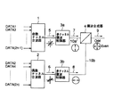
図1は本発明の一実施形態による直交偏波多重伝送装置の構成を示すブロック図である。ここでは、それぞれ異なる波長の2nチャネルの光信号DATA1〜DATA(2n)を波長多重する例を示す。光信号DATA1〜DATA(2n)は、送信波長が小さい順に並んでいるものとし、この段階ではランダム偏光である。
【0017】
本実施形態による直交偏波多重伝送装置には、奇数チャネル合波器1および偶数チャネル合波器2が設けられ、それらの入力ポートは予め設計した指定波長が入力しなければ通過することはできない。奇数チャネル合波器1は、奇数チャネル光信号DATA1、DATA3、・・・DATA(2n−1)を対応する入力ポートで入力して合波し奇数チャネル多重光5を出力する。偶数チャネル合波器2は、偶数チャネル光信号DATA2、DATA4、・・・DATA(2n) を対応する入力ポートで入力して合波し偶数チャネル多重光6を出力する。奇数チャネル多重光5および偶数チャネル多重光6は、この段階でもランダム偏光のままである。
【0018】
奇数チャネル多重光5および偶数チャネル多重光6は多チャネル偏波制御器3aおよび3bにそれぞれ入力する。多チャネル偏波制御器3aおよび3bは、これら多重光5および6を互いに直交する直線偏光である奇数チャネル垂直偏波多重光7および偶数チャネル水平偏波多重光8にそれぞれ変換する。奇数チャネル多重光5および偶数チャネル多重光6の各出力ポートは、偏波合成器4の所定入力ポートにそれぞれ偏波保持型ファイバ10aおよび10bによって光学的に接続されている。したがって、奇数チャネル垂直偏波多重光7および偶数チャネル水平偏波多重光8は偏波方向を維持したまま偏波合成器4に入力する。
【0019】
偏波合成器4は入力多重光の偏波方向を保持しながら合波する光部品であり、奇数チャネル垂直偏波多重光7および偶数チャネル水平偏波多重光8を合成して直交偏波多重光9を出力する。
【0020】
図2(A)は多チャネル偏波制御器3aの内部構成を示すブロック図であり、図2(B)は多チャネル偏波制御器3bの内部構成を示すブロック図である。なお、多チャネル偏波制御器3aおよび3bは偏波方向が入れ替わっているだけで、基本的に同様の構成で同様に動作するから、ここでは図2(A)の多チャネル偏波制御器3aについて説明する。
【0021】
上述したように、ランダム偏光である奇数チャネル多重光5は、多チャネル偏波制御器3aによって奇数チャネル垂直偏波多重光7に変換される。まず、奇数チャネル多重光5は、偏波分離器31aで垂直偏波成分の多重光35aと水平偏波成分の多重光36aに分岐する。
【0022】
一方の経路を伝播する水平偏波成分の多重光36aは、直線偏光を90度回転する偏波回転素子32aにより水平偏波から垂直偏波の多重光37aに変換され、遅延素子33aを通して結合器34aの一方の入力ポートに入力する。遅延素子33aは、結合器34aにて合波する際に他方の経路との干渉が生じないように光路長を補正する位相調整器である。ただし、本発明における多重光36aは複数の信号光(変調された光)からなるために、遅延素子33aによる位相調整は信号パルスが崩れない範囲で行う。
【0023】
他方の経路を伝播する垂直偏波成分の多重光35aは減衰器38aを通して結合器34aの他方の入力ポートに入力する。減衰器38aは、偏波回転素子32aおよび遅延素子33aの通過損失分と偏波分離器31aと結合器34aのポート間損失差とを考慮し、2経路の通過損失を一致させるために挿入されている。
【0024】
結合器34aは、2経路から入力する多重光を合波し、奇数チャネル垂直偏波多重光7を出力する。これによって入力多重光5の偏光状態が変動しても、奇数チャネル垂直偏波多重光7の出力チャネルパワーは一定となる。
【0025】
なお、図2(B)の多チャネル偏波制御器3bについては、図2(A)における偏光方向を入れ替えるだけで、基本的な構成及び動作は同じである。
【0026】
上述したように、多チャネル偏波制御器3aおよび3bにおける偏波分離器31aおよび31bの出力から偏波保持型が必要となり、多重光5および6まではランダム偏光のままであるから、通常の非偏波保持型の光学部品を使用することができる。
【0027】
また、偏波分離器31aおよび31bで全ての偏光を水平成分、垂直成分の直線偏光に分割し、偏波制御後に両経路の通過損失を一致させて再合波しているので、偏向子を用いてある特定の直線偏光成分を抽出するのとは異なり、入射偏光状態によって透過光パワーが変動することはない。偏波回転素子32aおよび32bについて海底通信で使用する信号帯域幅であれば、偏波回転角度の波長依存性は十分無視できるので、全ての信号光に対して直線偏光成分を90度回転させることができる。従って、直線偏光制御の波長依存性がほとんどなく、偏波消光比を十分確保した多チャネル偏波制御器として扱うことができる。また、当該偏波制御器は電気制御が不要であり、パッシブ光部品として扱うことができる。
【0028】
(実施例)
本発明の直交偏波多重伝送装置に入力する2n波の信号光は、波長帯域1539nm〜1565nmであり、100GHz間隔のITU−Tグリットを4等分した波長間隔25GHz(約0.2nm)を想定している。信号光数は最大130波になるが、今回は上記波長帯域の一部を利用し、32波とする(したがって、n=16)。
【0029】
奇数チャネル合波器1および偶数チャネル合波器2として、多チャネルを低損失に合波するのに有効な16ポート、50GHzアレイ導波路回折格子(AWG)を使用した。これにより、入力ポートに所定の信号波長を入力することによってそれぞれ16波の奇数チャネル多重光5および偶数チャネル多重光6を生成した。
【0030】
これら奇数チャネル多重光5および偶数チャネル多重光6は、多チャネル偏波制御器3aおよび3bによりそれぞれ直交する直線偏光の16波チャネル垂直多重光7および16波チャネル水平多重光8に変換され、それぞれ偏波保持ファイバ(PMF;Polarization Maintaining Fiber)10aおよび10bを伝播して偏波合成器4に入力する。
【0031】
偏波合成器4としては偏光ビームカプラ(PBC;Polarization Beam Coupler)を用いた。PBCは、垂直偏波および水平偏波を所定の入力ポートに入力することによって、それぞれの偏波方向を保持しながら損失1dB程度で合波し、32波の直交偏波多重光9を得ることができた。
【0032】
多チャネル偏波制御器3aおよび3bでは、偏波分離器31aおよび31bとして偏光ビームスプリッタ(PBS;Polarization Beam Splitter)を使用し、ランダム偏光を垂直成分、水平成分の2つの直線偏光に分岐した。
【0033】
直線偏光を所定の角度に回転する偏波回転素子32aおよび32bとしては、素子の膜厚を最適化することによって容易に偏光角度を90度回転させることができるλ/2板を使用した。
【0034】
減衰器38aおよび38bは減衰量固定型の偏波保持型を用いた。結合器34aおよび34bには2入力ポート偏波保持型3dB光カプラを使用した。両経路の光路長を調整する遅延素子33aおよび33bは、λ/2板と偏波保持型3dB光カプラとの間を接続する偏波保持ファイバの長さ(PMF長)を調整した遅延器、あるいは、可動式ミラー(プリズム)を用いて光路差を自由に調整可能な光ディレイラインによって実現した。これにより、合波後、光信号パルス劣化が生じないようにした。なお、この例における多チャネル偏波制御器3aおよび3bの通過損失は5.4dBであった。
【0035】
多チャネル偏波制御器3aおよび3bの基本特性を確認するために、偏波制御器を挿入する前と挿入した後で出力パワーの比較を行った。
【0036】
図3(A)は偏波制御器を挿入する前の出力パワー計測システムの概略図であり、図3(B)は偏波制御器を挿入した出力パワー計測システムの概略図である。図4は、偏波制御器を挿入する前と挿入した後で出力パワーを測定した結果を示すグラフである。
【0037】
まず、図3(A)に示すように、直線偏光のLD光源出力を偏波コントローラ(PC)で変化させ、偏向子透過後の光パワーをモニタした。この時の規格化した出力パワーの変化は、図4に「挿入前」としてプロットされている。これによれば、偏向子の透過方向に垂直な偏光を入射した場合、阻止量が30dB以上あることが分かる。
【0038】
これに対して図3(B)に示すように、本発明の偏波制御器を挿入すると、阻止量が1.4dBまで減少した。これは入射偏光状態に依らず、偏光子の透過方向成分をほぼ一定で透過している、すなわち直線偏光で出力していることを示している。
【0039】
なお、本評価では送信波長1565nmで行ったが、1539nmでも特性が変わらないことを確認している。また、上記出力パワー計測システムは光部品を個別に組み合わせて構成されたが、既知である光アイソレータの内部構成と類似していることから小型化が可能である。
【0040】
なお、本実施形態に用いられたAWGの入力ポート数および波長間隔は適用システムおよび装置構成に依存するものであり、この例に限定されるものではない。
【0041】
また、一般に信号光波長は等間隔に配置されるから、チャネル合波器1および2は周期性を持つAWGが有効に適用される。非等間隔の信号光を扱う場合には複数個のバンドパスフィルタの透過反射を組み合わせたフィルタタイプ合波器を使用することができる。
【0042】
さらに、偏波合成器4のPBCの代わりに、偏波保持型インターリーバを使用しても良い。PBCは直交する2つの直線偏波を低損失に合波するものであるが、インターリーバは、あらかじめ設計した入力信号波長(奇数波長側、偶数波長側)の信号間ノイズを除去しながら、低損失で合波する機能を有する。このために、AWGのアイソレーション(隣接ポートの阻止量)が不十分な場合に、インターリーバは伝送特性を向上するためにしばしば使用される光部品である。
【0043】
(他の実施形態)
図5は本発明の他の実施形態による直交偏波多重伝送装置の多チャネル偏波制御器3bの内部構成を示すブロック図である。上述したように、他方の多チャネル偏波制御器3aも同様の構成を有するので説明は省略する。
【0044】
図5に示すように、多チャネル偏波制御器3bで使用する光部品の調整を精度良く行うために、電圧可変式を用いることができる。例えば、減衰器38_Vbに電圧可変式アッテネータ(VOA;Variable Optical Attenuator)を使用し、偏波回転素子32_Vbに印加電圧によって偏光面が回転するファラデー回転デバイスを使用することができる。さらに、遅延素子33bとして可動式ミラー(プリズム)を用いた調整可能な光ディレイラインを使用することで、信号パルスを崩さない程度の適切な位相調整が可能となる。
【0045】
【発明の効果】
以上説明したように、本発明によれば、直交偏波多重を決定する偏波合成器の入力直前に多チャネル偏波制御器を設けて直線偏波制御を行っているために、偏波制御器以前の信号光の偏波状態を全く考慮する必要がない。このため、送信波長光源から偏波制御器の入力部に至る全ての光部品および装置構成を、従来の非偏波保持型にすることができ、高価な偏波保持型光部品を必要以上に使用しなくてよい。また、スプライス箇所、光コネクタ接続部や光部品通過による偏波消光比劣化への対策を考慮する必要もない。さらに奇数/偶数の2つの波長群単位で、一括してランダム偏光を直線偏光に変換しているので、個別に偏波制御するよりもはるかに部品点数が少なくて済む。
【図面の簡単な説明】
【図1】本発明の一実施形態による直交偏波多重伝送装置の構成を示すブロック図である。
【図2】(A)は多チャネル偏波制御器3aの内部構成を示すブロック図であり、(B)は多チャネル偏波制御器3bの内部構成を示すブロック図である。
【図3】(A)は偏波制御器を挿入する前の出力パワー計測システムの概略図であり、(B)は偏波制御器を挿入した出力パワー計測システムの概略図である。
【図4】偏波制御器を挿入する前と挿入した後で出力パワーを測定した結果を示すグラフである。
【図5】本発明の他の実施形態による直交偏波多重伝送装置の多チャネル偏波制御器3bの内部構成を示すブロック図である。
【符号の説明】
1 奇数チャネル合波器
2 偶数チャネル合波器
3a 多チャネル偏波制御器
3b 多チャネル偏波制御器
4 偏波合成器
5 奇数チャネル多重光
6 偶数チャネル多重光
7 奇数チャネル垂直偏波多重光
8 偶数チャネル水平偏波多重光
9 直交偏波多重光
10a 偏波保持型ファイバ
10b 偏波保持型ファイバ[0001]
TECHNICAL FIELD OF THE INVENTION
The present invention relates to a wavelength division multiplexing transmission technique in the field of optical communication, and more particularly to an orthogonal polarization multiplexing transmission apparatus that controls the polarization state of transmission signal light to realize high-density wavelength division multiplexing transmission.
[0002]
[Prior art]
At present, in the field of optical communication, so-called wavelength multiplex transmission, in which a plurality of signal lights having different wavelengths are multiplexed on one optical fiber and transmitted, in order to realize long-distance, large-capacity transmission, has become mainstream. This makes it possible to easily increase the transmission capacity of the existing transmission line.
[0003]
However, in order to multiplex a large number of signal lights within a limited amplification band like a submarine repeater, the wavelength intervals of the signal lights have to be increased. In this case, interference called coherent crosstalk occurs between the leaked light from the adjacent wavelength signal and the signal light itself, causing signal degradation. In addition, a nonlinear phenomenon called four-wave mixing occurs during optical fiber transmission, which also causes signal degradation.
[0004]
As means for solving these problems, a so-called orthogonal polarization multiplexing method in which the polarization states of adjacent signal lights are orthogonal to each other during wavelength multiplexing is effective, and energetically studied. Generally, four-wave mixing occurs remarkably when the adjacent polarization states are parallel and adversely affects the transmission characteristics. However, when the adjacent polarization states are orthogonalized, they can be suppressed because there is no parallel component. In addition, if light can be received at the receiving side while maintaining orthogonality, it is possible to avoid coherent crosstalk and completely separate individual signals by combining polarization separation and wavelength separation.
[0005]
At present, the transmission rate (bit rate) per signal light wave is mainly 10 Gb / s, but it is expected that the transmission rate will be further increased in the future. That is, the optical spectrum of the signal light tends to expand, and the influence of coherent crosstalk tends to further increase. Therefore, orthogonal polarization multiplexing is an indispensable technology in high-density and high-speed wavelength multiplex transmission, and various technologies for providing a high-quality multiplexing device have been proposed.
[0006]
For example, Japanese Patent Laying-Open No. 2002-217832 (Patent Document 1) describes a polarization control device for independently controlling each polarization state and restoring orthogonality between adjacent channels. Specifically, after once separating the signal light wavelength for each channel using an optical demultiplexer, the polarization control is individually performed, and the wavelength is multiplexed again using an optical multiplexer. This controls the wavelength-division multiplexed light in an arbitrary polarization state to be orthogonally polarized.
[0007]
Japanese Patent Laying-Open No. 2001-298415 (Patent Document 2) discloses an optical multiplexing circuit that stabilizes polarization maintenance of multiplexed lights orthogonal to each other and improves transmission quality. Specifically, using a polarization-maintaining AWG (Arrayed Waveguide Grating), odd-channel multiplexed light and even-channel multiplexed light are generated from a plurality of signal lights having linearly polarized light. Polarization control is performed on one of the even-numbered channel multiplexed lights to generate odd-numbered and even-numbered channel multiplexed lights orthogonal to each other, and orthogonal polarization multiplexing is realized by multiplexing them. .
[0008]
Japanese Patent Application Laid-Open No. Sho 59-210414 (Patent Document 3) discloses a polarization compensator that separates incident light into two orthogonal linearly polarized light components, matches one of the polarization directions with the other, and then synthesizes the components. Is disclosed.
[0009]
[Patent Document 1]
Japanese Patent Application Laid-Open No. 2002-217832 (specification paragraph numbers 0021 and 0025, FIG. 1)
[Patent Document 2]
JP 2001-298415 A (specification paragraph numbers 0015 to 0016, 0025, FIG. 1)
[Patent Document 3]
JP-A-59-210414 (1st to 18th lines in the upper right column on
[0010]
[Problems to be solved by the invention]
However, in the polarization control device described in
[0011]
The optical multiplexing circuit described in
[0012]
The polarization compensator described in Patent Literature 3 is intended to adjust the polarization of single-channel light before being incident on an optical modulator, and does not adjust the polarization of modulated signal light. Absent.
[0013]
An object of the present invention is to provide an orthogonal polarization multiplexing transmission apparatus that can realize orthogonal polarization multiplexing of a plurality of signal lights without complicating the configuration using the same non-polarization maintaining type optical component as in the related art. It is in.
[0014]
[Means for Solving the Problems]
The orthogonal polarization multiplexing transmission apparatus according to the present invention is an apparatus that receives a plurality of signal lights having different wavelengths and multiplexes and transmits such that the polarization directions of adjacent signal lights are orthogonal to each other. First combining means for combining odd-numbered signal lights to generate a first multiplexed light, and second combining means for combining even-numbered signal lights in the plurality of signal lights to generate a second multiplexed light; First polarization control means for converting the first multiplexed light into linearly polarized light in a first direction to generate a first linearly polarized light multiplexed light, and converting the second multiplexed light in a second direction orthogonal to the first direction. A second polarization controller for converting the light into linearly polarized light to generate a second linearly polarized light multiplexed light, and multiplexing the first linearly polarized light multiplexed light and the second linearly polarized light multiplexed light while maintaining the respective polarization states; Polarization combining means for generating the orthogonal polarization multiplexed light, And butterflies.
[0015]
The first combining means and the first polarization control means are coupled by a non-polarization maintaining fiber, the first polarization control means and the polarization combining means are coupled by a polarization maintaining fiber, The second combining means and the second polarization control means are coupled by a non-polarization maintaining fiber, and the second polarization control means and the polarization combining means are coupled by a polarization maintaining fiber. It is characterized by.
[0016]
BEST MODE FOR CARRYING OUT THE INVENTION
FIG. 1 is a block diagram showing a configuration of an orthogonal polarization multiplexing transmission apparatus according to an embodiment of the present invention. Here, an example in which 2n-channel optical signals DATA1 to DATA (2n) having different wavelengths are wavelength-multiplexed will be described. The optical signals DATA1 to DATA (2n) are arranged in ascending order of the transmission wavelength, and are random polarized at this stage.
[0017]
The orthogonal polarization multiplexing transmission apparatus according to the present embodiment is provided with an odd-numbered
[0018]
The odd channel multiplexed
[0019]
The polarization combiner 4 is an optical component for multiplexing while maintaining the polarization direction of the input multiplexed light. The polarization combiner 4 combines the odd channel vertical polarization multiplexed
[0020]
FIG. 2A is a block diagram showing the internal configuration of the
[0021]
As described above, the odd-channel multiplexed
[0022]
The multiplexed light 36a of the horizontal polarization component propagating in one path is converted from the horizontal polarization into the multiplexed light 37a of the vertical polarization by the
[0023]
The multiplexed light 35a of the vertically polarized component propagating in the other path is input to the other input port of the
[0024]
The
[0025]
Note that the basic configuration and operation of the
[0026]
As described above, the polarization maintaining type is required from the outputs of the
[0027]
In addition,
[0028]
(Example)
The 2n-wave signal light input to the orthogonal polarization multiplex transmission apparatus of the present invention has a wavelength band of 1539 nm to 1565 nm, and assumes a wavelength interval of 25 GHz (about 0.2 nm) obtained by dividing an ITU-T grid at 100 GHz intervals into four equal parts. are doing. Although the maximum number of signal lights is 130, this time, a part of the above-mentioned wavelength band is used, and the number of signal lights is set to 32 (thus n = 16).
[0029]
As the odd-numbered
[0030]
The odd channel multiplexed
[0031]
As the polarization combiner 4, a polarization beam coupler (PBC) was used. The PBC multiplexes with a loss of about 1 dB while maintaining the respective polarization directions by inputting the vertical polarization and the horizontal polarization to predetermined input ports to obtain 32 orthogonal polarization multiplexed
[0032]
In the
[0033]
As the
[0034]
As the
[0035]
In order to confirm the basic characteristics of the
[0036]
FIG. 3A is a schematic diagram of an output power measurement system before a polarization controller is inserted, and FIG. 3B is a schematic diagram of an output power measurement system with a polarization controller inserted. FIG. 4 is a graph showing the results of measuring the output power before and after inserting the polarization controller.
[0037]
First, as shown in FIG. 3A, the output of the linearly polarized LD light source was changed by a polarization controller (PC), and the optical power after passing through the deflector was monitored. The change of the normalized output power at this time is plotted as “before insertion” in FIG. According to this, it is understood that the amount of rejection is 30 dB or more when polarized light perpendicular to the transmission direction of the deflector is incident.
[0038]
On the other hand, as shown in FIG. 3B, when the polarization controller of the present invention was inserted, the amount of rejection was reduced to 1.4 dB. This indicates that the component in the transmission direction of the polarizer is transmitted almost uniformly, that is, the component is output as linearly polarized light regardless of the incident polarization state.
[0039]
Although the evaluation was performed at a transmission wavelength of 1565 nm, it was confirmed that the characteristics did not change even at 1539 nm. Further, the output power measurement system is configured by individually combining optical components. However, since the output power measurement system is similar to the known internal configuration of the optical isolator, the size can be reduced.
[0040]
The number of input ports and the wavelength interval of the AWG used in the present embodiment depend on the applied system and the device configuration, and are not limited to this example.
[0041]
In addition, since the signal light wavelengths are generally arranged at equal intervals, a periodic AWG is effectively applied to the
[0042]
Further, instead of the PBC of the polarization combiner 4, a polarization maintaining interleaver may be used. The PBC combines two orthogonal linear polarizations with low loss, while the interleaver removes inter-signal noise at a predesigned input signal wavelength (odd-wavelength side and even-wavelength side) while removing low noise. It has the function of multiplexing due to loss. For this reason, when the isolation of the AWG (the amount of blocking of an adjacent port) is insufficient, the interleaver is an optical component often used to improve transmission characteristics.
[0043]
(Other embodiments)
FIG. 5 is a block diagram showing the internal configuration of the
[0044]
As shown in FIG. 5, a variable voltage type can be used in order to accurately adjust optical components used in the
[0045]
【The invention's effect】
As described above, according to the present invention, the multi-channel polarization controller is provided immediately before the input of the polarization combiner for determining the orthogonal polarization multiplexing, and the linear polarization control is performed. There is no need to consider the polarization state of the signal light before the device. For this reason, all the optical components and the device configuration from the transmission wavelength light source to the input section of the polarization controller can be made conventional non-polarization maintaining type, and expensive polarization maintaining type optical components become unnecessary. No need to use. Also, there is no need to consider measures against degradation of the polarization extinction ratio due to the passage of a splice, an optical connector connection, or an optical component. Furthermore, since random polarized light is converted into linear polarized light collectively for each of the two wavelength groups of odd / even numbers, the number of components is much smaller than that of individually controlling the polarization.
[Brief description of the drawings]
FIG. 1 is a block diagram illustrating a configuration of an orthogonal polarization multiplex transmission device according to an embodiment of the present invention.
FIG. 2A is a block diagram illustrating an internal configuration of a
FIG. 3A is a schematic diagram of an output power measurement system before a polarization controller is inserted, and FIG. 3B is a schematic diagram of an output power measurement system with a polarization controller inserted.
FIG. 4 is a graph showing results of measuring output power before and after inserting a polarization controller.
FIG. 5 is a block diagram showing an internal configuration of a
[Explanation of symbols]
DESCRIPTION OF
Claims (8)
前記複数の信号光における奇数番目の信号光を合成して第1多重光を生成する第1合成手段と、
前記複数の信号光における偶数番目の信号光を合成して第2多重光を生成する第2合成手段と、
前記第1多重光を第1方向の直線偏光に変換して第1直線偏光多重光を生成する第1偏波制御手段と、
前記第2多重光を前記第1方向と直交する第2方向の直線偏光に変換して第2直線偏光多重光を生成する第2偏波制御手段と、
前記第1直線偏光多重光および前記第2直線偏光多重光を各偏光状態を維持しながら合波して前記直交偏波多重光を生成する偏波合成手段と、
を有することを特徴とする直交偏波多重伝送装置。In a device for inputting a plurality of signal lights having different wavelengths and multiplexing and transmitting such that the polarization directions of adjacent signal lights are orthogonal to each other,
First combining means for combining odd-numbered signal lights in the plurality of signal lights to generate a first multiplexed light;
Second combining means for combining the even-numbered signal lights in the plurality of signal lights to generate a second multiplexed light;
First polarization control means for converting the first multiplexed light into linearly polarized light in a first direction to generate a first linearly polarized light multiplexed light;
Second polarization control means for converting the second multiplexed light into linearly polarized light in a second direction orthogonal to the first direction to generate a second linearly polarized light multiplexed light;
Polarization combining means for combining the first linearly polarized light multiplexed light and the second linearly polarized light multiplexed light while maintaining respective polarization states to generate the orthogonally polarized light multiplexed light;
An orthogonal polarization multiplex transmission device comprising:
前記第2合成手段と前記第2偏波制御手段とは非偏波保持型ファイバで結合され、前記第2偏波制御手段と前記偏波合成手段とは偏波保持型ファイバで結合されている、
ことを特徴とする請求項1記載の直交偏波多重伝送装置。The first combining means and the first polarization control means are coupled by a non-polarization maintaining fiber, the first polarization control means and the polarization combining means are coupled by a polarization maintaining fiber,
The second combining means and the second polarization control means are coupled by a non-polarization maintaining fiber, and the second polarization control means and the polarization combining means are coupled by a polarization maintaining fiber. ,
The orthogonal polarization multiplex transmission device according to claim 1, wherein:
前記第1多重光を互いに直交する第1偏光方向成分および第2偏光方向成分の多重光に分離し、それぞれ第1経路および第2経路へ出力する第1偏波分離手段と、
前記第2経路の多重光の偏光方向を90度回転させて第1偏光方向と同方向の第3多重光を生成する第1偏波回転手段と、
前記第1経路および前記第2経路の光路長差を補正する第1光路長補正手段と、
前記第1経路および前記第2経路の経路損失差を補正する第1減衰手段と、
前記光路長差および前記経路損失差が補正された前記第1経路および前記第2経路の多重光を直線偏波を維持して合波し、前記第1直線偏光多重光を生成する第1結合手段と、
を有し、
前記第2偏波制御手段は、
前記第2多重光を互いに直交する前記第1偏光方向成分および前記第2偏光方向成分の多重光に分離し、それぞれ第3経路および第4経路へ出力する第2偏波分離手段と、
前記第3経路の多重光の偏光方向を90度回転させて第2偏光方向と同方向の第4多重光を生成する第2偏波回転手段と、
前記第3経路および前記第4経路の光路長差を補正する第2光路長補正手段と、
前記第3経路および前記第4経路の経路損失差を補正する第2減衰手段と、
前記光路長差および前記経路損失差が補正された前記第3経路および前記第4経路の多重光を直線偏波を維持して合波し、前記第2直線偏光多重光を生成する第2結合手段と、
を有することを特徴とする請求項1記載の直交偏波多重伝送装置。The first polarization control means includes:
First polarization separation means for separating the first multiplexed light into multiplexed lights of a first polarization direction component and a second polarization direction component orthogonal to each other, and outputting the multiplexed lights to a first path and a second path, respectively;
First polarization rotating means for rotating the polarization direction of the multiplexed light of the second path by 90 degrees to generate third multiplexed light in the same direction as the first polarization direction;
First optical path length correcting means for correcting an optical path length difference between the first path and the second path;
First attenuation means for correcting a path loss difference between the first path and the second path;
A first coupling for generating the first linearly polarized light multiplexed light by multiplexing the multiplexed lights of the first path and the second path with the optical path length difference and the path loss difference corrected while maintaining linear polarization; Means,
Has,
The second polarization control means includes:
Second polarization separation means for separating the second multiplexed light into multiplexed lights of the first polarization direction component and the second polarization direction component orthogonal to each other, and outputting the multiplexed lights to a third path and a fourth path, respectively;
Second polarization rotation means for rotating the polarization direction of the multiplexed light of the third path by 90 degrees to generate fourth multiplexed light in the same direction as the second polarization direction;
Second optical path length correction means for correcting the optical path length difference between the third path and the fourth path;
Second damping means for correcting a path loss difference between the third path and the fourth path;
A second coupling that combines the multiplexed lights of the third path and the fourth path, in which the optical path length difference and the path loss difference are corrected, while maintaining linear polarization, and generates the second linearly polarized light multiplexed light; Means,
2. The orthogonal polarization multiplex transmission apparatus according to claim 1, comprising:
前記第2光路長補正手段は、前記第2結合手段に入力する同一偏波方向の2つの多重光の間で干渉が生じないように、かつ、信号パルスを崩さないように位相を調整する遅延素子からなる、
ことを特徴とする請求項3記載の直交偏波多重伝送装置。The first optical path length correcting means is a delay for adjusting a phase so as not to cause interference between two multiplexed lights having the same polarization direction and input to the first coupling means, and not to break a signal pulse. Consisting of elements,
The second optical path length correction means is a delay for adjusting a phase so as not to cause interference between two multiplexed lights having the same polarization direction and input to the second coupling means, and not to destroy a signal pulse. Consisting of elements,
4. The orthogonal polarization multiplex transmission device according to claim 3, wherein:
Priority Applications (1)
| Application Number | Priority Date | Filing Date | Title |
|---|---|---|---|
| JP2003040469A JP2004253931A (en) | 2003-02-19 | 2003-02-19 | Orthogonal polarization multiplex transmitter |
Applications Claiming Priority (1)
| Application Number | Priority Date | Filing Date | Title |
|---|---|---|---|
| JP2003040469A JP2004253931A (en) | 2003-02-19 | 2003-02-19 | Orthogonal polarization multiplex transmitter |
Publications (1)
| Publication Number | Publication Date |
|---|---|
| JP2004253931A true JP2004253931A (en) | 2004-09-09 |
Family
ID=33024313
Family Applications (1)
| Application Number | Title | Priority Date | Filing Date |
|---|---|---|---|
| JP2003040469A Withdrawn JP2004253931A (en) | 2003-02-19 | 2003-02-19 | Orthogonal polarization multiplex transmitter |
Country Status (1)
| Country | Link |
|---|---|
| JP (1) | JP2004253931A (en) |
Cited By (11)
| Publication number | Priority date | Publication date | Assignee | Title |
|---|---|---|---|---|
| JP2007150558A (en) * | 2005-11-25 | 2007-06-14 | Oki Electric Ind Co Ltd | Optical code division multiplexing transmission reception method and optical code division multiplexing transmission reception apparatus |
| JP2008141669A (en) * | 2006-12-05 | 2008-06-19 | Fujitsu Ltd | Device for controlling polarization orthogonalization |
| JP2010166242A (en) * | 2009-01-14 | 2010-07-29 | Nippon Telegr & Teleph Corp <Ntt> | Optical transmitter and method |
| JP2010212835A (en) * | 2009-03-09 | 2010-09-24 | Kddi Corp | Optical transmitter and optical communication system |
| EP2343846A2 (en) | 2010-01-12 | 2011-07-13 | Hitachi, Ltd. | Polarization multiplexing transmitter and transmission system |
| US8086108B2 (en) | 2007-07-25 | 2011-12-27 | Panasonic Corporation | Optical transmission/reception device and optical communication system using the same |
| US8406577B2 (en) | 2007-12-28 | 2013-03-26 | Sumitomo Osaka Cement Co., Ltd. | Optical modulator |
| US8570644B2 (en) | 2008-12-26 | 2013-10-29 | Sumitomo Osaka Cement Co., Ltd. | Optical modulator |
| US8737840B2 (en) | 2010-04-30 | 2014-05-27 | Fujitsu Limited | Optical transmission system, transmitter, receiver and method |
| JP2016082481A (en) * | 2014-10-20 | 2016-05-16 | 日本電信電話株式会社 | Optical multiplexing system |
| WO2024036975A1 (en) * | 2022-08-16 | 2024-02-22 | 青岛海信宽带多媒体技术有限公司 | Optical module |
-
2003
- 2003-02-19 JP JP2003040469A patent/JP2004253931A/en not_active Withdrawn
Cited By (14)
| Publication number | Priority date | Publication date | Assignee | Title |
|---|---|---|---|---|
| US7747170B2 (en) | 2005-11-25 | 2010-06-29 | Oki Electric Industry Co., Ltd. | Optical code division multiplexing transmission/reception method and optical code division multiplexing transmission/reception device |
| JP4655904B2 (en) * | 2005-11-25 | 2011-03-23 | 沖電気工業株式会社 | Optical code division multiplexing transmission / reception method and optical code division multiplexing transmission / reception apparatus |
| JP2007150558A (en) * | 2005-11-25 | 2007-06-14 | Oki Electric Ind Co Ltd | Optical code division multiplexing transmission reception method and optical code division multiplexing transmission reception apparatus |
| JP2008141669A (en) * | 2006-12-05 | 2008-06-19 | Fujitsu Ltd | Device for controlling polarization orthogonalization |
| US8086108B2 (en) | 2007-07-25 | 2011-12-27 | Panasonic Corporation | Optical transmission/reception device and optical communication system using the same |
| US8406577B2 (en) | 2007-12-28 | 2013-03-26 | Sumitomo Osaka Cement Co., Ltd. | Optical modulator |
| US8570644B2 (en) | 2008-12-26 | 2013-10-29 | Sumitomo Osaka Cement Co., Ltd. | Optical modulator |
| JP2010166242A (en) * | 2009-01-14 | 2010-07-29 | Nippon Telegr & Teleph Corp <Ntt> | Optical transmitter and method |
| JP2010212835A (en) * | 2009-03-09 | 2010-09-24 | Kddi Corp | Optical transmitter and optical communication system |
| EP2343846A2 (en) | 2010-01-12 | 2011-07-13 | Hitachi, Ltd. | Polarization multiplexing transmitter and transmission system |
| US8417126B2 (en) | 2010-01-12 | 2013-04-09 | Hitachi, Ltd. | Polarization multiplexing transmitter and transmission system |
| US8737840B2 (en) | 2010-04-30 | 2014-05-27 | Fujitsu Limited | Optical transmission system, transmitter, receiver and method |
| JP2016082481A (en) * | 2014-10-20 | 2016-05-16 | 日本電信電話株式会社 | Optical multiplexing system |
| WO2024036975A1 (en) * | 2022-08-16 | 2024-02-22 | 青岛海信宽带多媒体技术有限公司 | Optical module |
Similar Documents
| Publication | Publication Date | Title |
|---|---|---|
| US10651627B2 (en) | Photonic integrated circuit | |
| JP4181742B2 (en) | Cross-phase modulation suppressor and optical communication system in wavelength division multiplexing optical transmission system | |
| US20030138254A1 (en) | Light branching/inserting apparatus and light branching apparatus using wavelength selection filter | |
| US8731402B2 (en) | Orthogonally-combining wavelength selective switch multiplexer and systems and methods using same | |
| US9319169B2 (en) | Orthogonally-combining interleaving filter multiplexer and systems and methods using same | |
| US6904240B1 (en) | Optical multiplexing apparatus and optical multiplexing method | |
| US8861966B2 (en) | Method and system for band blocking in an optical telecommunication network | |
| KR20010075468A (en) | Wdm-channel equalizer | |
| JP2004253931A (en) | Orthogonal polarization multiplex transmitter | |
| US9854336B2 (en) | Systems and methods for coupling a fiber to a polarization sensitive photonic integrated circuit | |
| WO2018193835A1 (en) | Bidirectional optical transmission system and bidirectional optical transmission method | |
| US20030026529A1 (en) | Optical demultiplexer | |
| WO2011162269A1 (en) | Multiplexer/demultiplexer and multiplexing/demultiplexing method | |
| TW202318051A (en) | On-chip integrated wavelength division multiplexer and chip | |
| JP5207993B2 (en) | Optical transmission apparatus and method | |
| KR20040072688A (en) | System for Polarization Mode Dispersion Compensation | |
| US6411413B1 (en) | Method and apparatus for performing dispersion compensation without a change in polarization and a transmitter incorporating same | |
| JP5367316B2 (en) | Optical regenerator | |
| US20050201758A1 (en) | Optical signal degradation compensator | |
| JP4047004B2 (en) | Method and apparatus for controlling optical wavelength tunable filter | |
| JP4137440B2 (en) | Optical device connection method and optical device | |
| JP3314745B2 (en) | Optical insertion / separation device and optical transmission device having the same | |
| JP2005348270A (en) | Optical add/drop multiplexing apparatus | |
| JP3058265B2 (en) | Optical multiplexer / demultiplexer used for WDM optical transmission system | |
| JP4030935B2 (en) | Optical pulse transmission device |
Legal Events
| Date | Code | Title | Description |
|---|---|---|---|
| A300 | Withdrawal of application because of no request for examination |
Free format text: JAPANESE INTERMEDIATE CODE: A300 Effective date: 20060509 |