JP2004253233A - Inorganic powder-containing resin-coated electric wire, two-layer coated electric wire, inorganic powder-containing resin-coated coil, two-layer coated electric wire coil, inorganic material-coated insulating coil and method of manufacturing the same, and electric device having inorganic material-coated insulating coil and manufacturing thereof Method - Google Patents
Inorganic powder-containing resin-coated electric wire, two-layer coated electric wire, inorganic powder-containing resin-coated coil, two-layer coated electric wire coil, inorganic material-coated insulating coil and method of manufacturing the same, and electric device having inorganic material-coated insulating coil and manufacturing thereof Method Download PDFInfo
- Publication number
- JP2004253233A JP2004253233A JP2003042085A JP2003042085A JP2004253233A JP 2004253233 A JP2004253233 A JP 2004253233A JP 2003042085 A JP2003042085 A JP 2003042085A JP 2003042085 A JP2003042085 A JP 2003042085A JP 2004253233 A JP2004253233 A JP 2004253233A
- Authority
- JP
- Japan
- Prior art keywords
- coil
- coated
- electric wire
- resin
- inorganic powder
- Prior art date
- Legal status (The legal status is an assumption and is not a legal conclusion. Google has not performed a legal analysis and makes no representation as to the accuracy of the status listed.)
- Granted
Links
Images
Landscapes
- Insulated Conductors (AREA)
- Insulating Of Coils (AREA)
Abstract
【課題】本発明の課題は、コスト的に民生機器にも適用可能な耐熱性絶縁性コイルを提供することにある。
【解決手段】耐熱性および絶縁性を兼ね備えた無機粉体を、比較的高価なシリコーン樹脂、変性シリコーン樹脂、あるいはポリカルボシランなどのケイ素を含む樹脂以外の樹脂溶液に分散させ、その無機粉体分散樹脂溶液を導体上に塗布して焼き付けることによって無機粉体含有樹脂被覆電線21を作製する。そして、この電線21を巻回してコイルを作製した後、そのコイルを、樹脂が分解し且つ分解物が気化するような温度にさらすと、導体上に残存する無機粉体が耐熱絶縁層14を形成する。
【選択図】 図1An object of the present invention is to provide a heat-resistant insulating coil which can be applied to consumer equipment in terms of cost.
An inorganic powder having both heat resistance and insulating properties is dispersed in a relatively expensive resin solution other than a silicone resin, a modified silicone resin, or a resin containing silicon such as polycarbosilane. An inorganic powder-containing resin-coated electric wire 21 is prepared by applying a dispersion resin solution on a conductor and baking the conductor. Then, after winding the electric wire 21 to produce a coil, when the coil is exposed to a temperature at which the resin is decomposed and the decomposed substance is vaporized, the inorganic powder remaining on the conductor forms the heat-resistant insulating layer 14. Form.
[Selection diagram] Fig. 1
Description
【0001】
【発明の属する技術分野】
本発明は、耐熱性絶縁被覆層を有する電線からなるコイルおよびその製造方法、そのコイルを作製するための電線およびコイル、ならびにそのコイルを用いた電気機器およびその製造方法に関する。
【0002】
【従来の技術】
従来、電線の絶縁は、合成樹脂を導体に被覆することにより行われてきた。ところで、この合成樹脂として、いわゆる耐熱性樹脂と呼ばれるポリアミドイミドやポリイミドなどが知られている。これらの合成樹脂の耐熱温度は国際電気標準会議(IEC)や米国NEMA規格などにより摂氏220度および摂氏240度と規定されており、これらの合成樹脂を被覆した耐熱性絶縁電線はその信頼性から比較的過酷な環境を生み出す電気機器(電動機など。)などに採用されている。しかし、極めて過酷な環境下ではこれらの合成樹脂の寿命は比較的短くなり、その電気機器について比較的頻繁に部品交換などを行う必要がある。この問題を解決するために合成樹脂よりもさらに耐熱性に優れる無機物質(セラミックなどの絶縁性を有する物質。)を被覆した電線が開発されている(特許文献1参照。)。周知のとおり、無機物質は非常に堅く可撓性に乏しいため、電線に無機物質を被覆してからコイルを作製するのは、極めて困難である。そこで、この電線に、加熱処理することによって無機質化するシリコーン樹脂、変性シリコーン樹脂、あるいはポリカルボシランなどのケイ素を含む樹脂を被覆しておいて、コイルを作製した後にこの電線を高温にさらしてセラミック電線コイルを作製することが行われている。なお、このとき、膜厚などを考慮してあらかじめ無機粉体が混入されることもある。また、上記に示した絶縁電線は全て、当業者に既知の方法(以下、この方法を常法という。)によって作製することができる。
【0003】
【特許文献1】
特開2000−11768号公報(第2−3項、図1)
【0004】
【発明が解決しようとする課題】
しかし、シリコーン樹脂、変性シリコーン、あるいはポリカルボシランなどは比較的高価であるため、コスト的に民生用機器へ適用が難しい。
本発明の課題は、コスト的に民生機器にも適用可能な耐熱性絶縁性コイルを提供することにある。
【0005】
【課題を解決するための手段】
請求項1に記載の無機粉体含有樹脂被覆電線は、導体が、無機粉体が分散されている樹脂(ケイ素を骨格の一部に含む樹脂を除く。)によって被覆される電線である。なお、ここにいう「樹脂」は、ポリエチレン、ポリプロピレン、ポリ塩化ビニル、ポリビニルアセタール、ポリカーボネイト、ポリアルファ−メチルスチレン、ポリアクリル酸、ポリアクリル酸エステル、ポリメタアクリル酸、ポリメタクリル酸エステル、ポリエステル(ポリエチレンテレフタレート、ポリブチレンテレフタレート、不飽和ポリエステルなど)、ポリアミド(ナイロン(登録商標)など)、ポリサルホン、ポリエーテルサルホン、ポリアリレート、ポリフェニルエーテル、ポリエーテルエーテルケトン、ポリエーテルケトン、ポリアミドイミド、ポリエーテルイミド、ポリエステルイミド、フッ素樹脂(ポリテトラフルオロエチレン、FEPあるいはPFAなど)、ポリオレフィン、ポリビニルホルマール、ポリウレタン、あるいはこれらの樹脂の骨格を任意に組み合わせた共重合体(ランダム、ブロック、グラフト、あるいは交互共重合体など)などである。また、これらの樹脂に、熱によってこれらの樹脂の分解を促進する添加剤をあらかじめ添加しておいてもよい。ここに例示列挙した樹脂の中にはシリコーン樹脂、変性シリコーン樹脂、あるいはポリカルボシランなどよりも高価な樹脂も含まれるが、将来的に価格が下がれば使用可能である。また、ここにいう「導体」は、銅線、アルミニウム線、銀線、ニッケル線、クロム線、ステンレス線、銀めっき線、銀クラッド線、ニッケルめっき銅線、あるいはニッケルクラッド銅線などである。また、「ケイ素を骨格の一部に含む樹脂」とは、シリコーン樹脂、変性シリコーン樹脂、あるいはポリカルボシランなどである。また、ここにいう「無機粉体」は、窒化ケイ素などから構成される粉体である。窒化ケイ素などのセラミック原料は、絶縁性に優れており、樹脂の熱分解温度で変質することがない。
【0006】
この電線を、樹脂が分解し且つ分解物が気化するような温度にさらすと、導体上に残存する無機粉体が皮膜を形成する。また、この電線はその樹脂により適度な可撓性を有するためコイルを作製しやすい。このため、シリコーン樹脂、変性シリコーン樹脂、あるいはポリカルボシランなどの比較的高価な樹脂を使用しなくても、セラミック電線コイルを得ることができる。したがって、コスト的に民生機器にも適用可能な耐熱性絶縁性コイルを作製することができる。また、この電線は、従来の絶縁電線製造装置を用いて製造することができる。このため、新たな製造装置を導入する必要がない。したがって、製造コストを低く維持することが可能である。
【0007】
請求項2に記載の無機粉体含有樹脂被覆電線は、請求項1に記載の無機粉体含有樹脂被覆電線であって、樹脂は、摂氏400度以下、好ましくは摂氏300度以下、より好ましくは摂氏200度以下で分解する。なお、樹脂の分解は、解重合であっても、酸化分解であっても、解重合と酸化分解とが混じったかたちであっても、その他の分解であってもよい。
【0008】
一般に、このような電線は、電気機器などに用いられることが多い。電気機器によっては、その製造工程の中で、摂氏200度程度の温度でその電気機器の一部を処理する工程が設けられる場合がある。このため、このような工程においてコイルにされた無機粉体含有樹脂被覆電線の樹脂を分解して無機物質で被覆された電線からなるコイルを作製すると、電線の樹脂を熱分解させる工程を別に設ける必要をなくすことができる。また、電気機器の一部を損傷させることがなければ、そのような工程において電気機器の一部を摂氏300度あるいは摂氏400度で処理しても同様の効果を得ることができる。しかし、省エネルギーを考慮すると、低温である方が好ましい。
【0009】
請求項3に記載の無機粉体含有樹脂被覆電線は、請求項1または2に記載の無機粉体含有樹脂被覆電線であって、無機粉体の形状は、鱗片形状である。なお、無機粉体が鱗片形状をとる場合は、樹脂溶液への分散性に優れているとともに、配向性に優れている。このような無機粉体として、例えば、窒化ケイ素または二硫化モリブデンなどが挙げられる。
【0010】
鱗片形状の粉体は、層状に重なりやすい、このため、球状の粉体よりも粒子間の接着面積が大きくなり、被膜化しやすいと推察される。したがって、ピンホールなどの欠陥のない皮膜を容易に形成することができる。
請求項4に記載の無機粉体含有樹脂被覆電線は、請求項1から3のいずれかに記載の無機粉体含有樹脂被覆電線であって、無機粉体は、窒化ケイ素を成分として含む。
【0011】
窒化ケイ素は、摂氏2000度以上の融点を有する。このため、窒化ケイ素を主成分とする耐熱絶縁層を形成することができれば、極めて過酷な環境下でも、その電線の寿命は、ポリイミド樹脂やポリアミドイミド樹脂などを被覆した電線の寿命よりも長くなるはずである。このため、電気機器の部品交換などの回数を低減できる。
【0012】
請求項5に記載の無機粉体含有樹脂被覆電線は、請求項1から4のいずれかに記載の無機粉体含有樹脂被覆電線であって、無機粉体の平均粒子径は、0.01マイクロメートルから1.5マイクロメートル、好ましくは0.1マイクロメートルから1.5マイクロメートルである。なお、この無機粉体の平均粒子径の測定は、「堀場製作所製のレーザ回折/散乱式粒子径分布測定装置、LA−300」を用いて行った。また、測定は、添付のマニュアルに従って行われた。
【0013】
無機粉体の平均粒子径は、無機粉体被膜の成膜性、樹脂溶液への分散性および無機粉体の取り扱いなどに大きな影響を及ぼす。無機粉体の平均粒子径が0.01マイクロメートルから1.5マイクロメートルである場合、良好な無機粉体被膜が形成される。これは、おそらく無機粉体間の接着面積が十分に確保されるためであると推測される。しかし、平均粒子系が0.01マイクロメートル付近である場合は、樹脂溶液への分散性が比較的悪くなり、また、無機粉体の取り扱いも難しくなる。したがって、無機粉体の平均粒子径は、0.1マイクロメートルから1.5マイクロメートルであることが好ましい。このようにすれば、樹脂溶液への分散性および無機粉体の取り扱いが改善される。
【0014】
請求項6に記載の二層被覆電線は、請求項1から5のいずれかに記載の無機粉体含有樹脂被覆電線が、無機粉体を含まない樹脂(ケイ素を骨格の一部に含む樹脂を除く。)で被覆される電線である。なお、ここにいう「樹脂」は、請求項1から5の樹脂と同じであっても異なっていてもよい。
無機粉体含有樹脂被覆電線の表面には、無機粉体の一部が突出していることがある。このため、この電線は滑走性に問題があることが多い。これは、コイルを高速で作製するときに大きな問題になる。このため、ここでは、無機粉体含有樹脂被覆電線をさらに樹脂で被覆して電線の滑走性を確保した。したがって、コイルを高速で作製することができる。
【0015】
請求項7に記載の二層被覆電線は、請求項6に記載の二層被覆電線であって、無機粉体を含まない樹脂(ケイ素を骨格の一部に含む樹脂を除く。)は、滑性剤を含有する。ここにいう「滑性剤」は、ポリオレフィン、脂肪酸エステル、ワックス、あるいはフッ素樹脂微粉末などである。
ここでは、樹脂が滑性剤を含有する。このため、電線の滑走性をさらに向上させることができる。したがって、コイルをさらに高速で作製することができる。
【0016】
請求項8に記載の二層被覆電線は、請求項6に記載の二層被覆電線であって、無機粉体が分散されている樹脂(ケイ素を骨格の一部に含む樹脂を除く。)の熱分解温度は、無機粉体を含まない樹脂(ケイ素を骨格の一部に含む樹脂を除く。)の熱分解温度よりも高い。
ここでは、無機粉体が分散されている樹脂の熱分解温度が、無機粉体を含まない樹脂の熱分解温度よりも高い。このため、電線を高温にさらしたとき、最外層の樹脂が先に分解する。したがって、分解物の気化が速やかに行われ、無機粉体で被覆される電線の形状を良好に保つことができる。
【0017】
請求項9に記載の無機粉体含有樹脂被覆電線コイルは、請求項1から5のいずれかに記載の無機粉体含有樹脂被覆電線から作製される。
一般的に、無機物質で被覆された電線は可撓性に乏しい。このため、無機物質で被覆された電線を巻回してコイルを作製するのは困難である。一方、無機粉体含有樹脂被覆電線は、ある程度の可撓性を有する。したがって、容易にコイルを作製することができる。そして、コイル作製後に樹脂を熱分解して除去すると、無機物質で被覆されたコイルを作製することができる。
【0018】
請求項10に記載の二層被覆電線コイルは、請求項6から8のいずれかに記載の二層被覆電線から作製される。
一般的に、無機物質で被覆された電線は可撓性に乏しい。このため、無機物質で被覆された電線を巻回してコイルを作製するのは困難である。一方、二層被覆電線は、ある程度の可撓性を有する。したがって、容易にコイルを作製することができる。そして、コイル作製後に樹脂を熱分解して除去すると、無機物質で被覆されたコイルを作製することができる。
【0019】
請求項11に記載の無機物質被覆絶縁コイルの製造方法は、コイル作製工程と無機物質被覆絶縁コイル作製工程とを備える。コイル作製工程では、請求項1から5のいずれかに記載の無機粉体含有樹脂被覆電線、あるいは請求項6から8のいずれかに記載の二層被覆電線が巻回されてコイルが作製される。無機物質被覆絶縁コイル作製工程では、無機粉体含有樹脂被覆電線、あるいは二層被覆電線に含有される樹脂が熱分解されて無機物質被覆絶縁コイルが作製される。
【0020】
ここでは、この製造方法が実施されると、コイル作製工程で、請求項1から5のいずれかに記載の無機粉体含有樹脂被覆電線、あるいは請求項6から8のいずれかに記載の二層被覆電線が巻回されてコイルが作製される。そして、無機物質被覆絶縁コイル作製工程で、無機粉体含有樹脂被覆電線、あるいは二層被覆電線に含有される樹脂が熱分解されて無機物質被覆絶縁コイルが作製される。このため、この製造方法によれば、無機物質で被覆された電線から構成されるコイルを容易に作製することができる。
【0021】
請求項12に記載の無機物質被覆絶縁コイルは、請求項11に記載の製造方法により得られるコイルである。
このコイルは、無機物質で被覆される電線から構成される。無機物質、例えばセラミックスなどは、樹脂なみの優れた絶縁性を有する。また、このセラミックスなどは樹脂よりも優れた耐熱性を有することが多い。このため、極めて過酷な環境下でも、その電線の寿命は、従来のポリイミド樹脂やポリアミドイミド樹脂などで被覆される電線の寿命よりも長くなるはずである。このため、電気機器の部品交換などの回数を低減できる。
【0022】
請求項13に記載の電気機器は、請求項12に記載の無機物質被覆絶縁コイルを用いた電気機器である。なお、ここにいう「電気機器」とは、変圧器、電動機あるいは発電機などである。
この無機物質被覆絶縁コイルを、変圧器、電動機または発電機などの電気機器に用いれば、その電気機器に関して損失を低減させることができる。
【0023】
請求項14に記載の電気機器の製造方法は、導入工程と圧粉鉄心作製工程とを備える。導入工程では、請求項9に記載の無機粉体含有樹脂被覆電線コイル、あるいは請求項10に記載の二層被覆電線コイルに対して圧粉鉄心の原料粉体が導入される。圧粉鉄心作製工程では、圧粉鉄心の原料粉体が圧縮され、さらに焼結されることによって圧粉鉄心が作製される。なお、ここにいう「焼結」は、圧粉鉄心のバインダを分解し、鉄心をさらに強固にする工程をいい、通常摂氏200から400度の間で行われる。そして、圧粉鉄心作製工程では、コイルに含有される樹脂が熱分解されることによって無機物質被覆絶縁コイルが生成する。
【0024】
ここでは、この製造方法が実施されると、導入工程で、請求項9に記載の無機粉体含有樹脂被覆電線コイル、あるいは請求項10に記載の二層被覆電線コイルに対して圧粉鉄心の原料粉体が導入される。次に、圧粉鉄心作製工程で、圧粉鉄心の原料粉体が圧縮され、さらに焼結されることによって圧粉鉄心が作製される。そして、圧粉鉄心作製工程で、コイルに含有される樹脂が熱分解されることによって無機物質被覆絶縁コイルが生成する。このため、圧粉鉄心をコイル内に形成すると同時にコイルに絶縁層を形成することができる。したがって、生産工程を増加させることなく、無機物質被覆絶縁コイルに鉄心を導入することができる。また、このようにしてコイルに圧粉鉄心を形成すれば、コイル内およびコイルを構成する電線間に生じる内表面の凹部に原料粉体が入り込むため、コイルの導体の占積率を向上することができる。
【0025】
請求項15に記載の電気機器の製造方法は、鉄心入りコイル作製工程と熱処理工程とを備える。鉄心入りコイル作製工程では、請求項1から5のいずれかに記載の無機粉体含有樹脂被覆電線、あるいは請求項6から8のいずれかに記載の二層被覆電線が鉄心に巻回されて鉄心入りコイルが作製される。熱処理工程では、鉄心入りコイルが熱処理される。なお、ここにいう「熱処理」には、鉄心の焼結の他、鉄心の磁気特性向上を図るもの、鉄心の酸化被膜を生成するものも含まれる。そして、熱処理工程で、鉄心入りコイルのコイル部分に含有される樹脂が熱分解されることによって無機物質被覆絶縁コイルが生成する。なお、ここにいう「鉄心」は、積層鉄心、圧粉鉄心あるいはアモルファス鉄心などである。
【0026】
ここでは、この製造方法を実施すると、鉄心入りコイル作製工程で、請求項1から5のいずれかに記載の無機粉体含有樹脂被覆電線、あるいは請求項6から8のいずれかに記載の二層被覆電線が鉄心に巻回されて鉄心入りコイルが作製される。次に、熱処理工程で、鉄心入りコイルが熱処理される。そして、熱処理工程で、鉄心入りコイルのコイル部分に含有される樹脂が熱分解されることによって無機物質被覆絶縁コイルが生成する。このため、未焼結の鉄心を用いると、鉄心を焼結すると同時にコイルに絶縁層を形成することができる。したがって、生産工程を増加させることなく、無機物質被覆絶縁コイルを作製することができる。
【0027】
請求項16に記載の電気機器の製造方法は、請求項15に記載の電気機器の製造方法であって、熱処理工程では、鉄心入りコイルのコイル部分に含有される樹脂の熱分解による無機物質被覆絶縁コイルの生成と、鉄心の酸被および焼鈍の少なくとも一方とが行われる。なお、ここにいう「電気機器」として、特に高温環境下で使用される場合に好適である電動機、例えば高速で回転するターボ圧縮機、あるいは高圧環境下で使用される全密閉圧縮機に用いられる電動機などが挙げられる。
【0028】
ここでは、熱処理工程で、鉄心入りコイルのコイル部分に含有される樹脂の熱分解による無機物質被覆絶縁コイルの生成と、鉄心の酸被および焼鈍の少なくとも一方とが行われる。このため、電気機器の生産工程が簡素化され電気機器の生産性が向上する。
【0029】
【発明の実施の形態】
[本実施の形態において作製される電線の形態]
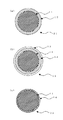
図1には、本実施の形態において作製される電線の形態を示した。なお、ここでは、本発明に係る電線の形態を電線の断面図により説明する。図1の(a)には、無機粉体含有樹脂被覆電線21の断面図を示す。この無機粉体含有樹脂被覆電線21は、導体11と、その導体11を被覆する無機粉体含有樹脂層12とからなる。また、図1の(b)には、二層被覆電線22の断面図を示す。この二層被覆電線22は、導体11、その導体11を被覆する無機粉体含有樹脂層12、およびその無機粉体含有樹脂層12をさらに被覆する樹脂層13からなる。なお、この樹脂層13は、潤滑剤を含有していてもかまわない。最後に、図1の(c)には、無機物質被覆絶縁コイルを構成する絶縁電線23の断面図を示す。この絶縁電線23は、導体11と無機物質絶縁層14とからなる。
【0030】
[本実施の形態に使用される素材]
(1)導体11
本実施の形態において使用可能な導体11は、銅線、アルミニウム線、銀線、ニッケル線、クロム線、ステンレス線、銀めっき線、銀クラッド銅線、ニッケルめっき銅線、あるいはニッケルクラッド銅線などである。
【0031】
(2)樹脂
本実施の形態において使用可能な樹脂は、ポリエチレン、ポリプロピレン、ポリ塩化ビニル、ポリビニルアセタール、ポリカーボネイト、ポリアルファ−メチルスチレン、ポリアクリル酸、ポリアクリル酸エステル、ポリメタアクリル酸、ポリメタクリル酸エステル、ポリエステル(ポリエチレンテレフタレート、ポリブチレンテレフタレート、不飽和ポリエステルなど)、ポリアミド(ナイロン(登録商標)など)、ポリサルホン、ポリエーテルサルホン、ポリアリレート、ポリフェニルエーテル、ポリエーテルエーテルケトン、ポリエーテルケトン、ポリアミドイミド、ポリエーテルイミド、ポリエステルイミド、フッ素樹脂(ポリテトラフルオロエチレン、FEPあるいはPFAなど)、ポリオレフィン、ポリビニルホルマール、ポリウレタン、あるいはこれらの樹脂の骨格を任意に組み合わせた共重合体(ランダム、ブロック、グラフト、あるいは交互共重合体など)である。また、これらの樹脂は、ブレンドされてもかまわない。なお、本実施の形態では、樹脂の灰分はできるだけ少ないのが好ましい。また、樹脂を導体に被覆させるとき、その樹脂は溶液の形態をとるのが好ましい。なお、その樹脂溶液は常法に適用できる程度の粘度および樹脂濃度を有するのが好ましい。
【0032】
(3)無機粉体
本実施の形態において使用可能な無機粉体は、窒化ケイ素、酸化ケイ素、炭化ケイ素、アルミナ、シリカ、マグネシアなどを成分とする粉体である。また、複数の種類の粉体を混合して用いてもかまわない。
(4)潤滑剤
本実施の形態において使用可能な潤滑剤は、ポリオレフィン、脂肪酸エステル、ワックス、あるいはフッ素樹脂微粉末などである。これらの潤滑剤は、ブレンドされてもかまわない。また、これらの潤滑剤は、任意の割合で樹脂に混合される。
【0033】
[本実施の形態における電線の作製方法]
本実施の形態に係る電線21,22は全て、当業者に既知の方法(常法)によって作製することができる。二層被覆電線22を作製する場合も、常法による。この場合、ディップ層を取り替えて同じ工程を2度繰り返せばよい。
[本実施の形態におけるコイルの作製方法]
本実施の形態に係るコイルも全て、当業者に既知の方法(常法)によって作製することができる。
【0034】
[本実施の形態における無機物質被覆絶縁電線23および無機物質被覆絶縁コイルの作製方法]
本実施の形態に係る無機物質被覆絶縁電線23または無機物質被覆絶縁コイルは、無機粉体含有樹脂被覆電線21もしくは無機粉体含有樹脂被覆コイル、または二層被覆電線22もしくは二層被覆コイルを、対応する樹脂の熱分解温度以上の温度条件下に曝して樹脂を熱分解させ、分解物を気化させることによって作製される。
【0035】
[本実施の形態に示す電線21,22,23およびコイルの特徴]
(1)
本実施の形態に係る無機物質含有樹脂被覆電線21は、シリコーン樹脂、変性シリコーン樹脂、あるいはポリカルボシラン樹脂などの高価な樹脂を用いることなく無機材料被覆絶縁電線23に転換させることができる。
【0036】
(2)
本実施の形態に係る二層被覆電線22は、高速巻回によるコイルの作製に対して耐え得り、また、シリコーン樹脂、変性シリコーン樹脂、あるいはポリカルボシラン樹脂などの高価な樹脂を用いることなく無機材料被覆絶縁電線23に転換させることができる。
【0037】
【実施例】
以下、本発明の実施例について説明する。なお、本発明は以下の実施例に限定されるものではない。
(1)窒化ケイ素粉体分散ポリウレタン樹脂溶液の調製
窒化ケイ素粉体40部をポリウレタン樹脂塗料(樹脂濃度20%)100部に加えた後、攪拌機により攪拌して窒化ケイ素粉体をポリウレタン樹脂塗料に分散させた。なお、ここで用いた窒化ケイ素粉体の平均粒子系は、0.75マイクロメートルであった。
【0038】
(2)窒化ケイ素粉体含有ポリウレタン樹脂被覆電線
窒化ケイ素粉体が分散されたポリウレタン樹脂塗料を常法により導体11に塗布した後、焼成して、窒化ケイ素粉体含有ポリウレタン樹脂被覆電線を作製した。なお、導体11には、直径0.5mmのニッケルめっき銅線を用いた。作製された窒化ケイ素粉体含有ポリウレタン樹脂被覆電線の外径は、0.535mmであった。また、窒化ケイ素粉体含有ポリウレタン樹脂層の厚さは、0.0175mmであった。
【0039】
(3)自己潤滑性ポリウレタン樹脂塗料の調製
ワックス3部をポリウレタン樹脂塗料(樹脂濃度20%)100部に加えた後、攪拌機により攪拌してワックスをポリウレタン樹脂塗料に溶解させた。
(4)自己潤滑性二層被覆電線の作製
ワックスを添加したポリウレタン樹脂塗料を常法により窒化ケイ素粉体含有ポリウレタン樹脂被覆電線に塗布した後、焼成して、二層被覆電線を作製した。
【0040】
(5)窒化ケイ素被覆絶縁電線の作製
窒化ケイ素粉体含有ポリウレタン樹脂被覆電線を、摂氏400度のオーブン内に所定時間放置した。この結果、ポリウレタン樹脂は熱分解し、分解物は気化し、導体11上に窒化ケイ素からなる絶縁層が形成された。なお、二層被覆電線を用いた場合も同様の結果が得られた。
【0041】
(6)窒化ケイ素被覆絶縁コイルの作製
窒化ケイ素粉体含有ポリウレタン樹脂被覆電線をコイル状に巻線した後、コイル形状を保持した状態で摂氏400度のオーブン内に所定時間放置した。この結果、ポリウレタン樹脂は熱分解し、分解物は気化し、窒化ケイ素からなる絶縁層を有するコイルが得られた。なお、二層被覆電線を用いた場合は、コイルの作製を高速で行うことができた。また、二層被覆電線を先と同様に処理しても、窒化ケイ素からなる絶縁層を有するコイルが得られた。
【0042】
【発明の効果】
請求項1に係る無機粉体含有樹脂被覆電線を、樹脂が分解し且つ分解物が気化するような温度にさらすと、導体上に残存する無機粉体が皮膜を形成する。また、この電線はその樹脂により適度な可撓性を有するためコイルを作製しやすい。このため、シリコーン樹脂、変性シリコーン樹脂、あるいはポリカルボシランなどの比較的高価な樹脂を使用しなくても、セラミック電線コイルを得ることができる。したがって、コスト的に民生機器にも適用可能な耐熱性絶縁性コイルを作製することができる。また、この電線は、従来の絶縁電線製造装置を用いて製造することができる。このため、新たな製造装置を導入する必要がない。したがって、製造コストを低く維持することが可能である。
【0043】
請求項2に係る無機粉体含有樹脂被覆電線のような電線は、電気機器などに用いられることが多い。電気機器によっては、その製造工程の中で、摂氏200度程度の温度でその電気機器の一部を処理する工程が設けられる場合がある。このため、このような工程においてコイルにされた無機粉体含有樹脂被覆電線の樹脂を分解して無機物質で被覆された電線からなるコイルを作製すると、電線の樹脂を熱分解させる工程を別に設ける必要をなくすことができる。また、電気機器の一部を損傷させることがなければ、そのような工程において電気機器の一部を摂氏300度あるいは摂氏400度で処理しても同様の効果を得ることができる。しかし、省エネルギーを考慮すると、低温である方が好ましい。
【0044】
請求項3に係る無機粉体含有樹脂被覆電線の被覆層に含まれる無機粉体の形状は、鱗片形状である。鱗片形状の粉体は、層状に重なりやすい、このため、球状の粉体よりも粒子間の接着面積が大きくなり、被膜化しやすいと推察される。したがって、ピンホールなどの欠陥のない皮膜を容易に形成することができる。
請求項4に係る無機粉体含有樹脂被覆電線の被覆層に含まれる無機粉体は、窒化ケイ素を成分として含む。窒化ケイ素は、摂氏2000度以上の融点を有する。このため、窒化ケイ素を主成分とする耐熱絶縁層を形成することができれば、極めて過酷な環境下でも、その電線の寿命は、ポリイミド樹脂やポリアミドイミド樹脂などを被覆した電線の寿命よりも長くなるはずである。このため、電気機器の部品交換などの回数を低減できる。
【0045】
請求項5に記載の無機粉体含有樹脂被覆電線に含まれる無機粉体の平均粒子径が0.01マイクロメートルから1.5マイクロメートルである場合、良好な無機粉体被膜が形成される。しかし、平均粒子系が0.01マイクロメートル付近である場合は、樹脂溶液への分散性が比較的悪くなり、また、無機粉体の取り扱いも難しくなる。したがって、無機粉体の平均粒子系は、0.1マイクロメートルから1.5マイクロメートルであることが好ましい。このようにすれば、樹脂溶液への分散性および無機粉体の取り扱いが改善される。
【0046】
請求項6に係る二層被覆電線は、無機粉体含有樹脂被覆電線をさらに樹脂で被覆した電線である。このため、無機粉体含有樹脂被覆電線よりも速くコイルを作製することができる。
請求項7に係る二層被覆電線の最外層の樹脂は、滑性剤を含有する。このため、電線の滑走性をさらに向上させることができる。したがって、コイルをさらに高速で作製することができる。
【0047】
請求項8に係る二層被覆電線を高温にさらしたとき、最外層の樹脂が優先的に分解する。したがって、分解物の気化が速やかに行われ、無機粉体で被覆される電線の形状を良好に保つことができる。
請求項9に係る無機粉体含有樹脂被覆電線コイルは、無機粉体含有樹脂被覆電線から容易に作製することができる。そして、コイル作製後に樹脂を熱分解して除去すると、無機物質で被覆されたコイルを作製することができる。
【0048】
請求項10に係る二層被覆電線コイルは、二層被覆電線から容易に作製することができる。そして、コイル作製後に樹脂を熱分解して除去すると、無機物質で被覆されたコイルを作製することができる。
請求項11に係る無機物質被覆絶縁コイルの製造方法では、無機物質で被覆された電線から構成されるコイルを容易に作製することができる。
【0049】
請求項12に係る無機物質被覆絶縁コイルは、無機物質で被覆される電線から構成される。無機物質、例えばセラミックスなどは、樹脂なみの優れた絶縁性を有する。また、このセラミックスなどは樹脂よりも優れた耐熱性を有することが多い。このため、極めて過酷な環境下でも、その電線の寿命は、従来のポリイミド樹脂やポリアミドイミド樹脂などで被覆される電線の寿命よりも長くなるはずである。このため、電気機器の部品交換などの回数を低減できる。
【0050】
請求項13に係る電気機器に、無機物質被覆絶縁コイルを用いれば、その電気機器に関して損失を低減させることができる。
請求項14に係る電気機器の製造方法では、圧粉鉄心をコイル内に形成すると同時にコイルに絶縁層を形成することができる。したがって、生産工程を増加させることなく、無機物質被覆絶縁コイルに鉄心を導入することができる。また、このようにしてコイルに圧粉鉄心を形成すれば、コイル内およびコイルを構成する電線間に生じる内表面の凹部に原料粉体が入り込むため、コイルの導体の占積率を向上することができる。
【0051】
請求項15に係る電気機器の製造方法では、未焼結の鉄心を用いると、鉄心を焼結すると同時にコイルに絶縁層を形成することができる。したがって、生産工程を増加させることなく、無機物質被覆絶縁コイルを作製することができる。
請求項16に係る電気機器の製造方法では、電気機器の生産工程が簡素化され電気機器の生産性が向上する。
【図面の簡単な説明】
【図1】本発明に係る(a)無機粉体含有樹脂被覆電線21、(b)二層被覆電線22および(c)無機物質被覆絶縁コイルを構成する無機物質被覆絶縁電線23の断面図。
【符号の説明】
11 導体
12 無機粉体含有樹脂層
13 樹脂層
14 無機物質絶縁層
21 無機粉体含有樹脂被覆電線
22 二層被覆電線
23 無機物質被覆絶縁コイルを構成する無機物質被覆絶縁電線[0001]
TECHNICAL FIELD OF THE INVENTION
The present invention relates to a coil made of an electric wire having a heat-resistant insulating coating layer and a method for manufacturing the coil, an electric wire and a coil for manufacturing the coil, an electric device using the coil, and a method for manufacturing the same.
[0002]
[Prior art]
Conventionally, insulation of an electric wire has been performed by coating a conductor with a synthetic resin. By the way, as the synthetic resin, polyamide imide, polyimide, and the like, which are so-called heat-resistant resins, are known. The heat-resistant temperature of these synthetic resins is specified at 220 degrees Celsius and 240 degrees Celsius by the International Electrotechnical Commission (IEC) and the United States NEMA standard. Used in electrical equipment (such as electric motors) that create a relatively harsh environment. However, in an extremely severe environment, the life of these synthetic resins is relatively short, and it is necessary to relatively frequently replace parts of the electric equipment. In order to solve this problem, an electric wire coated with an inorganic substance (a substance having an insulating property such as ceramics) having higher heat resistance than a synthetic resin has been developed (see Patent Document 1). As is well known, inorganic materials are very hard and poor in flexibility, so it is extremely difficult to produce a coil after coating the wire with the inorganic material. Therefore, this wire is coated with a silicone resin, a modified silicone resin, or a resin containing silicon such as polycarbosilane, which is made inorganic by heat treatment, and after making a coil, the wire is exposed to a high temperature. 2. Description of the Related Art Production of ceramic electric wire coils has been performed. At this time, an inorganic powder may be mixed in advance in consideration of the film thickness and the like. In addition, all of the above-described insulated wires can be manufactured by a method known to those skilled in the art (hereinafter, this method is referred to as an ordinary method).
[0003]
[Patent Document 1]
JP-A-2000-11768 (Section 2-3, FIG. 1)
[0004]
[Problems to be solved by the invention]
However, since silicone resins, modified silicones, polycarbosilanes, and the like are relatively expensive, it is difficult to apply them to consumer equipment in terms of cost.
An object of the present invention is to provide a heat-resistant insulating coil that can be applied to consumer equipment in terms of cost.
[0005]
[Means for Solving the Problems]
The inorganic powder-containing resin-coated electric wire according to
[0006]
When this electric wire is exposed to a temperature at which the resin decomposes and the decomposition product evaporates, the inorganic powder remaining on the conductor forms a film. In addition, since this electric wire has appropriate flexibility due to its resin, it is easy to manufacture a coil. Therefore, a ceramic electric wire coil can be obtained without using a relatively expensive resin such as a silicone resin, a modified silicone resin, or polycarbosilane. Therefore, a heat-resistant insulating coil which can be applied to consumer equipment in terms of cost can be manufactured. This electric wire can be manufactured using a conventional insulated wire manufacturing apparatus. Therefore, there is no need to introduce a new manufacturing device. Therefore, it is possible to keep the manufacturing cost low.
[0007]
The inorganic powder-containing resin-coated electric wire according to
[0008]
Generally, such electric wires are often used for electric equipment and the like. Some electric devices may include a step of processing a part of the electric device at a temperature of about 200 degrees Celsius in a manufacturing process thereof. For this reason, when a coil made of an electric wire coated with an inorganic substance is produced by decomposing the resin of the inorganic powder-containing resin-coated electric wire that has been made into a coil in such a process, a step of thermally decomposing the resin of the electric wire is separately provided. The need can be eliminated. In addition, as long as a part of the electric device is not damaged, a similar effect can be obtained by treating a part of the electric device at 300 degrees Celsius or 400 degrees Celsius in such a process. However, in consideration of energy saving, it is preferable that the temperature is low.
[0009]
An inorganic powder-containing resin-coated electric wire according to a third aspect is the inorganic powder-containing resin-coated electric wire according to the first or second aspect, wherein the shape of the inorganic powder is a scale shape. In the case where the inorganic powder has a scale shape, the inorganic powder is excellent in dispersibility in a resin solution and also excellent in orientation. Examples of such an inorganic powder include silicon nitride and molybdenum disulfide.
[0010]
It is presumed that the flake-shaped powder tends to overlap in a layered manner, so that the adhesion area between the particles is larger than that of the spherical powder, and the film is easily formed. Therefore, a film free from defects such as pinholes can be easily formed.
An inorganic powder-containing resin-coated electric wire according to
[0011]
Silicon nitride has a melting point above 2000 degrees Celsius. For this reason, if a heat-resistant insulating layer containing silicon nitride as a main component can be formed, the life of the electric wire will be longer than the life of an electric wire coated with a polyimide resin or a polyamide-imide resin, even in an extremely severe environment. Should be. For this reason, the number of times of replacement of parts of the electric equipment can be reduced.
[0012]
An inorganic powder-containing resin-coated electric wire according to claim 5 is the inorganic powder-containing resin-coated electric wire according to any one of
[0013]
The average particle size of the inorganic powder has a great influence on the film forming property of the inorganic powder coating, dispersibility in a resin solution, handling of the inorganic powder, and the like. When the average particle diameter of the inorganic powder is from 0.01 μm to 1.5 μm, a good inorganic powder coating is formed. This is presumably because the adhesion area between the inorganic powders is sufficiently ensured. However, when the average particle size is around 0.01 micrometers, dispersibility in the resin solution becomes relatively poor, and handling of the inorganic powder becomes difficult. Therefore, it is preferable that the average particle diameter of the inorganic powder is 0.1 μm to 1.5 μm. This improves dispersibility in the resin solution and handling of the inorganic powder.
[0014]
The two-layer coated electric wire according to claim 6, wherein the inorganic powder-containing resin-coated electric wire according to any one of
Part of the inorganic powder may protrude from the surface of the resin-coated electric wire containing the inorganic powder. For this reason, this electric wire often has a problem in sliding properties. This is a major problem when manufacturing coils at high speed. For this reason, here, the inorganic powder-containing resin-coated electric wire was further coated with resin to secure the sliding property of the electric wire. Therefore, the coil can be manufactured at a high speed.
[0015]
The two-layer covered electric wire according to claim 7 is the two-layer covered electric wire according to claim 6, wherein the resin containing no inorganic powder (excluding the resin containing silicon as a part of the skeleton) is smooth. Contains a sexual agent. The “lubricating agent” used herein is a polyolefin, a fatty acid ester, a wax, a fine powder of a fluororesin, or the like.
Here, the resin contains a lubricant. For this reason, the sliding property of the electric wire can be further improved. Therefore, the coil can be manufactured at higher speed.
[0016]
The two-layer covered electric wire according to claim 8 is the two-layer covered electric wire according to claim 6, wherein the resin is one in which an inorganic powder is dispersed (excluding a resin containing silicon as a part of a skeleton). The thermal decomposition temperature is higher than the thermal decomposition temperature of a resin containing no inorganic powder (excluding a resin containing silicon as a part of the skeleton).
Here, the thermal decomposition temperature of the resin in which the inorganic powder is dispersed is higher than the thermal decomposition temperature of the resin not containing the inorganic powder. Therefore, when the electric wire is exposed to a high temperature, the resin of the outermost layer is decomposed first. Therefore, the decomposition product is quickly vaporized, and the shape of the electric wire covered with the inorganic powder can be kept good.
[0017]
An inorganic powder-containing resin-coated electric wire coil according to a ninth aspect is manufactured from the inorganic powder-containing resin-coated electric wire according to any one of the first to fifth aspects.
In general, wires coated with an inorganic material have poor flexibility. For this reason, it is difficult to manufacture a coil by winding an electric wire coated with an inorganic substance. On the other hand, an inorganic powder-containing resin-coated electric wire has a certain degree of flexibility. Therefore, a coil can be easily manufactured. When the resin is thermally decomposed and removed after the coil is manufactured, a coil coated with an inorganic substance can be manufactured.
[0018]
A two-layer covered electric wire coil according to a tenth aspect is manufactured from the two-layer covered electric wire according to any one of the sixth to eighth aspects.
In general, wires coated with an inorganic material have poor flexibility. For this reason, it is difficult to manufacture a coil by winding an electric wire coated with an inorganic substance. On the other hand, a two-layer covered electric wire has a certain degree of flexibility. Therefore, a coil can be easily manufactured. When the resin is thermally decomposed and removed after the coil is manufactured, a coil coated with an inorganic substance can be manufactured.
[0019]
A method for manufacturing an inorganic material-coated insulated coil according to claim 11 includes a coil manufacturing step and an inorganic material-coated insulated coil manufacturing step. In the coil producing step, the inorganic powder-containing resin-coated electric wire according to any one of
[0020]
Here, when this manufacturing method is performed, the inorganic powder-containing resin-coated electric wire according to any one of
[0021]
An inorganic material-coated insulating coil according to a twelfth aspect is a coil obtained by the manufacturing method according to the eleventh aspect.
This coil is composed of an electric wire covered with an inorganic substance. Inorganic substances, for example, ceramics and the like have excellent insulating properties similar to resin. In addition, such ceramics and the like often have better heat resistance than resins. For this reason, even under an extremely severe environment, the life of the electric wire should be longer than the life of the electric wire covered with a conventional polyimide resin or polyamide-imide resin. For this reason, the number of times of replacement of parts of the electric equipment can be reduced.
[0022]
An electric device according to a thirteenth aspect is an electric device using the inorganic material-coated insulating coil according to the twelfth aspect. In addition, the "electric device" mentioned here is a transformer, a motor, a generator, or the like.
If this inorganic material-coated insulating coil is used for an electric device such as a transformer, a motor or a generator, the loss of the electric device can be reduced.
[0023]
A method for manufacturing an electric device according to a fourteenth aspect includes an introduction step and a dust core manufacturing step. In the introduction step, the raw material powder of the dust core is introduced into the inorganic powder-containing resin-coated wire coil according to the ninth aspect or the two-layer coated wire coil according to the tenth aspect. In the dust core manufacturing process, a powder core is manufactured by compressing and sintering the raw material powder of the dust core. The term “sintering” as used herein refers to a step of decomposing the binder of the dust core to further strengthen the core, and is usually performed at a temperature of 200 to 400 degrees Celsius. Then, in the dust core manufacturing process, the resin contained in the coil is thermally decomposed to generate an inorganic material-coated insulating coil.
[0024]
Here, when this manufacturing method is performed, in the introduction step, the powdered iron core is attached to the inorganic powder-containing resin-coated wire coil according to claim 9 or the two-layer coated wire coil according to claim 10. Raw material powder is introduced. Next, in a dust core manufacturing step, the powdered material of the dust core is compressed and further sintered to produce a dust core. Then, in the dust core manufacturing process, the resin contained in the coil is thermally decomposed to generate an inorganic material-coated insulating coil. Therefore, an insulating layer can be formed on the coil at the same time that the dust core is formed in the coil. Therefore, the iron core can be introduced into the inorganic material-coated insulating coil without increasing the number of production steps. In addition, when the dust core is formed in the coil in this manner, the raw material powder enters into the concave portion of the inner surface generated in the coil and between the electric wires constituting the coil, thereby improving the space factor of the coil conductor. Can be.
[0025]
A method for manufacturing an electric device according to a fifteenth aspect includes a step of making a cored coil and a heat treatment step. In the core-containing coil producing step, the inorganic powder-containing resin-coated electric wire according to any one of
[0026]
Here, when this manufacturing method is performed, the inorganic powder-containing resin-coated electric wire according to any one of
[0027]
A method for manufacturing an electric device according to a sixteenth aspect is the method for manufacturing an electric device according to the fifteenth aspect, wherein in the heat treatment step, the inorganic material is coated by thermal decomposition of a resin contained in a coil portion of the cored coil. The generation of the insulating coil and at least one of the acid coating and annealing of the iron core are performed. In addition, as the "electric device" here, an electric motor particularly suitable for use in a high-temperature environment, for example, a high-speed rotating turbo compressor, or used in a hermetic compressor used in a high-pressure environment And an electric motor.
[0028]
Here, in the heat treatment step, generation of an inorganic substance-coated insulating coil by thermal decomposition of a resin contained in the coil portion of the cored coil and at least one of acid coating and annealing of the core are performed. For this reason, the production process of the electric equipment is simplified, and the productivity of the electric equipment is improved.
[0029]
BEST MODE FOR CARRYING OUT THE INVENTION
[Form of electric wire manufactured in this embodiment]
FIG. 1 shows a form of an electric wire manufactured in the present embodiment. Here, the form of the electric wire according to the present invention will be described with reference to a cross-sectional view of the electric wire. FIG. 1A shows a cross-sectional view of an inorganic powder-containing resin-coated electric wire 21. The inorganic powder-containing resin-coated electric wire 21 includes a conductor 11 and an inorganic powder-containing
[0030]
[Material used in the present embodiment]
(1) Conductor 11
The conductor 11 that can be used in the present embodiment is, for example, a copper wire, an aluminum wire, a silver wire, a nickel wire, a chrome wire, a stainless steel wire, a silver plated wire, a silver clad copper wire, a nickel plated copper wire, or a nickel clad copper wire. It is.
[0031]
(2) Resin
Resins that can be used in the present embodiment are polyethylene, polypropylene, polyvinyl chloride, polyvinyl acetal, polycarbonate, polyalpha-methylstyrene, polyacrylic acid, polyacrylate, polymethacrylic acid, polymethacrylic ester, polyester (Polyethylene terephthalate, polybutylene terephthalate, unsaturated polyester, etc.), polyamide (nylon (registered trademark), etc.), polysulfone, polyether sulfone, polyarylate, polyphenyl ether, polyether ether ketone, polyether ketone, polyamide imide, Polyether imide, polyester imide, fluororesin (polytetrafluoroethylene, FEP or PFA, etc.), polyolefin, polyvinyl formal, poly Urethane, or a copolymer of any combination of skeleton of these resins (random, block, graft, or alternating copolymers). In addition, these resins may be blended. In the present embodiment, it is preferable that the ash content of the resin is as small as possible. When the conductor is coated with the resin, the resin preferably takes the form of a solution. Preferably, the resin solution has a viscosity and a resin concentration that can be applied to a conventional method.
[0032]
(3) Inorganic powder
The inorganic powder that can be used in the present embodiment is a powder containing silicon nitride, silicon oxide, silicon carbide, alumina, silica, magnesia, and the like as components. Further, a plurality of types of powder may be mixed and used.
(4) Lubricant
The lubricant that can be used in the present embodiment is a polyolefin, a fatty acid ester, a wax, or a fine powder of a fluororesin. These lubricants may be blended. These lubricants are mixed with the resin at an arbitrary ratio.
[0033]
[Method of Manufacturing Electric Wire in Present Embodiment]
All the
[Method of Manufacturing Coil According to Embodiment]
All the coils according to the present embodiment can also be manufactured by a method (an ordinary method) known to those skilled in the art.
[0034]
[Method for Manufacturing Inorganic Material-Coated
The inorganic material-coated
[0035]
[Characteristics of
(1)
The inorganic substance-containing resin-coated electric wire 21 according to the present embodiment can be converted to the inorganic material-coated insulated
[0036]
(2)
The two-layer covered
[0037]
【Example】
Hereinafter, examples of the present invention will be described. Note that the present invention is not limited to the following examples.
(1) Preparation of polyurethane resin solution in which silicon nitride powder is dispersed
After adding 40 parts of silicon nitride powder to 100 parts of the polyurethane resin paint (resin concentration 20%), the mixture was stirred with a stirrer to disperse the silicon nitride powder in the polyurethane resin paint. The average particle size of the silicon nitride powder used here was 0.75 micrometers.
[0038]
(2) Polyurethane resin-coated electric wire containing silicon nitride powder
A polyurethane resin coating material in which silicon nitride powder was dispersed was applied to the conductor 11 by an ordinary method, and then fired to produce a polyurethane resin-coated electric wire containing silicon nitride powder. The conductor 11 was a nickel-plated copper wire having a diameter of 0.5 mm. The outer diameter of the prepared silicon nitride powder-containing polyurethane resin-coated electric wire was 0.535 mm. The thickness of the polyurethane resin layer containing the silicon nitride powder was 0.0175 mm.
[0039]
(3) Preparation of self-lubricating polyurethane resin paint
After adding 3 parts of wax to 100 parts of the polyurethane resin paint (resin concentration 20%), the wax was dissolved in the polyurethane resin paint by stirring with a stirrer.
(4) Production of self-lubricating two-layer coated electric wire
The polyurethane resin coating material to which the wax was added was applied to the silicon resin powder-containing polyurethane resin-coated electric wire by a conventional method, and then baked to prepare a two-layer coated electric wire.
[0040]
(5) Production of silicon nitride coated insulated wire
The polyurethane resin-coated electric wire containing the silicon nitride powder was left in an oven at 400 degrees Celsius for a predetermined time. As a result, the polyurethane resin was thermally decomposed, the decomposed product was vaporized, and an insulating layer made of silicon nitride was formed on the conductor 11. Similar results were obtained when a two-layer coated electric wire was used.
[0041]
(6) Production of insulated coil coated with silicon nitride
After winding the silicon nitride powder-containing polyurethane resin-coated electric wire in a coil shape, the wire was left in an oven at 400 degrees Celsius for a predetermined time while maintaining the coil shape. As a result, the polyurethane resin was thermally decomposed, the decomposed product was vaporized, and a coil having an insulating layer made of silicon nitride was obtained. In addition, when the two-layer covered electric wire was used, the coil could be manufactured at high speed. In addition, a coil having an insulating layer made of silicon nitride was obtained by treating the two-layer covered electric wire in the same manner as above.
[0042]
【The invention's effect】
When the inorganic powder-containing resin-coated electric wire according to
[0043]
An electric wire such as the inorganic powder-containing resin-coated electric wire according to
[0044]
The shape of the inorganic powder contained in the coating layer of the inorganic powder-containing resin-coated electric wire according to claim 3 is a scale shape. It is presumed that the flake-shaped powder tends to overlap in a layered manner, so that the adhesion area between the particles is larger than that of the spherical powder, and the film is easily formed. Therefore, a film free from defects such as pinholes can be easily formed.
The inorganic powder contained in the coating layer of the inorganic powder-containing resin-coated electric wire according to
[0045]
When the average particle diameter of the inorganic powder contained in the inorganic powder-containing resin-coated electric wire according to claim 5 is from 0.01 μm to 1.5 μm, a good inorganic powder coating is formed. However, when the average particle size is around 0.01 micrometers, dispersibility in the resin solution becomes relatively poor, and handling of the inorganic powder becomes difficult. Therefore, the average particle system of the inorganic powder is preferably from 0.1 to 1.5 micrometers. This improves dispersibility in the resin solution and handling of the inorganic powder.
[0046]
The two-layer coated electric wire according to claim 6 is an electric wire obtained by further coating an inorganic powder-containing resin-coated electric wire with a resin. For this reason, the coil can be manufactured faster than the inorganic powder-containing resin-coated electric wire.
The resin of the outermost layer of the two-layer covered electric wire according to claim 7 contains a lubricant. For this reason, the sliding property of the electric wire can be further improved. Therefore, the coil can be manufactured at higher speed.
[0047]
When the double-layer coated electric wire according to claim 8 is exposed to a high temperature, the resin of the outermost layer is decomposed preferentially. Therefore, the decomposition product is quickly vaporized, and the shape of the electric wire covered with the inorganic powder can be kept good.
The inorganic powder-containing resin-coated electric wire coil according to claim 9 can be easily manufactured from the inorganic powder-containing resin-coated electric wire. When the resin is thermally decomposed and removed after the coil is manufactured, a coil coated with an inorganic substance can be manufactured.
[0048]
The two-layer covered electric wire coil according to claim 10 can be easily manufactured from the two-layer covered electric wire. When the resin is thermally decomposed and removed after the coil is manufactured, a coil coated with an inorganic substance can be manufactured.
According to the method of manufacturing an inorganic material-coated insulated coil according to the eleventh aspect, a coil including an electric wire coated with an inorganic material can be easily manufactured.
[0049]
An inorganic material-coated insulating coil according to a twelfth aspect is composed of an electric wire coated with an inorganic material. Inorganic substances, for example, ceramics and the like have excellent insulating properties similar to resin. In addition, such ceramics and the like often have better heat resistance than resins. For this reason, even under an extremely severe environment, the life of the electric wire should be longer than the life of the electric wire covered with a conventional polyimide resin or polyamide-imide resin. For this reason, the number of times of replacement of parts of the electric equipment can be reduced.
[0050]
When the inorganic material-coated insulating coil is used in the electric device according to
In the method for manufacturing an electric device according to claim 14, an insulating layer can be formed on the coil at the same time as the dust core is formed in the coil. Therefore, the iron core can be introduced into the inorganic material-coated insulating coil without increasing the number of production steps. In addition, when the dust core is formed in the coil in this manner, the raw material powder enters into the concave portion of the inner surface generated in the coil and between the electric wires constituting the coil, thereby improving the space factor of the coil conductor. Can be.
[0051]
In the method for manufacturing an electric device according to the fifteenth aspect, if an unsintered iron core is used, the core can be sintered and the insulating layer can be formed on the coil at the same time. Therefore, the inorganic material-coated insulating coil can be manufactured without increasing the number of production steps.
In the method for manufacturing an electric device according to the sixteenth aspect, the production process of the electric device is simplified, and the productivity of the electric device is improved.
[Brief description of the drawings]
FIG. 1 is a cross-sectional view of (a) an inorganic powder-containing resin-coated electric wire 21, (b) a two-layer coated
[Explanation of symbols]
11 conductor
12 Inorganic powder-containing resin layer
13 Resin layer
14 Insulation layer of inorganic material
21 Resin-coated electric wire containing inorganic powder
22 Double-layered wire
23 Insulated wire coated with inorganic material that constitutes an insulated coil coated with inorganic material
Claims (16)
請求項1に記載の無機粉体含有樹脂被覆電線(21)。The resin decomposes at 400 degrees Celsius or less, preferably 300 degrees Celsius or less, more preferably 200 degrees Celsius or less,
The resin-coated electric wire containing an inorganic powder according to claim 1.
請求項1または2に記載の無機粉体含有樹脂被覆電線(21)。The shape of the inorganic powder is a scale shape,
An inorganic powder-containing resin-coated electric wire (21) according to claim 1 or 2.
請求項1から3のいずれかに記載の無機粉体含有樹脂被覆電線(21)。The inorganic powder contains silicon nitride as a component,
An inorganic powder-containing resin-coated electric wire (21) according to any one of claims 1 to 3.
二層被覆電線(22)。The inorganic powder-containing resin-coated electric wire (21) according to any one of claims 1 to 5, which is coated with a resin containing no inorganic powder (excluding a resin containing silicon as part of the skeleton) (13). ,
Double-layer coated electric wire (22).
請求項6に記載の二層被覆電線(22)。The resin not containing the inorganic powder (excluding the resin containing silicon as a part of the skeleton) (13) contains a lubricant.
The two-layer coated electric wire (22) according to claim 6.
請求項6に記載の二層被覆電線(22)。The thermal decomposition temperature of the resin in which the inorganic powder is dispersed (excluding the resin containing silicon as a part of the skeleton) (12), Excluding resin) higher than the thermal decomposition temperature of (13),
The two-layer coated electric wire (22) according to claim 6.
前記無機粉体含有樹脂被覆電線(21)、あるいは前記二層被覆電線(22)に含有される樹脂を熱分解させて無機物質被覆絶縁コイルを作製する無機物質被覆絶縁コイル作製工程と、
を備える、無機物質被覆絶縁コイルの製造方法。A coil produced by winding the inorganic powder-containing resin-coated electric wire (21) according to any one of claims 1 to 5, or the double-layered electric wire (22) according to any one of claims 6 to 8. Manufacturing process,
An inorganic material-coated insulated coil producing step of thermally decomposing the resin contained in the inorganic powder-containing resin-coated electric wire (21) or the two-layer covered electric wire (22) to produce an inorganic material-coated insulated coil;
A method for producing an inorganic material-coated insulating coil, comprising:
前記圧粉鉄心の原料粉体を圧縮して、さらに焼結することによって圧粉鉄心を作製する圧粉鉄心作製工程と、
を備え、
前記圧粉鉄心作製工程において、前記コイルに含有される樹脂が熱分解されることによって無機物質被覆絶縁コイルが生成する、電気機器の製造方法。An introduction step of introducing a raw material powder of a dust core into the inorganic powder-containing resin-coated wire coil (21) according to claim 9 or the two-layer covered wire coil (22) according to claim 10;
Compressing the raw material powder of the dust core, and further sintering to produce a dust core,
With
The method for manufacturing an electric device, wherein in the powder core manufacturing step, an inorganic substance-coated insulating coil is generated by thermally decomposing a resin contained in the coil.
前記鉄心入りコイルを熱処理する熱処理工程と、
を備え、
前記熱処理工程において、前記鉄心入りコイルのコイル部分に含有される樹脂が熱分解されることによって無機物質被覆絶縁コイルが生成する、電気機器の製造方法。A coil with an iron core, wherein the inorganic powder-containing resin-coated electric wire (21) according to any one of claims 1 to 5 or the two-layer coated electric wire (22) according to any one of claims 6 to 8 is wound around an iron core. A core-containing coil manufacturing process for manufacturing
A heat treatment step of heat treating the cored coil;
With
A method for manufacturing an electric device, wherein in the heat treatment step, an inorganic material-coated insulating coil is generated by thermally decomposing a resin contained in a coil portion of the cored coil.
請求項15に記載の電気機器の製造方法。In the heat treatment step, generation of an inorganic material-coated insulating coil by thermal decomposition of a resin contained in the coil portion of the cored coil, and at least one of acid coating and annealing of the iron core,
A method for manufacturing the electric device according to claim 15.
Priority Applications (1)
| Application Number | Priority Date | Filing Date | Title |
|---|---|---|---|
| JP2003042085A JP4617634B2 (en) | 2003-02-20 | 2003-02-20 | Manufacturing method of electrical equipment |
Applications Claiming Priority (1)
| Application Number | Priority Date | Filing Date | Title |
|---|---|---|---|
| JP2003042085A JP4617634B2 (en) | 2003-02-20 | 2003-02-20 | Manufacturing method of electrical equipment |
Publications (2)
| Publication Number | Publication Date |
|---|---|
| JP2004253233A true JP2004253233A (en) | 2004-09-09 |
| JP4617634B2 JP4617634B2 (en) | 2011-01-26 |
Family
ID=33025459
Family Applications (1)
| Application Number | Title | Priority Date | Filing Date |
|---|---|---|---|
| JP2003042085A Expired - Fee Related JP4617634B2 (en) | 2003-02-20 | 2003-02-20 | Manufacturing method of electrical equipment |
Country Status (1)
| Country | Link |
|---|---|
| JP (1) | JP4617634B2 (en) |
Cited By (4)
| Publication number | Priority date | Publication date | Assignee | Title |
|---|---|---|---|---|
| WO2013054738A1 (en) * | 2011-10-11 | 2013-04-18 | 東特塗料株式会社 | Electrically insulated wire having multi-layered coating |
| WO2018088264A1 (en) * | 2016-11-08 | 2018-05-17 | アルプス電気株式会社 | Inductance element and method for manufacturing same |
| CN111863409A (en) * | 2020-09-03 | 2020-10-30 | 长兴索菲特电子股份有限公司 | Noise reduction type I-shaped inductor and manufacturing method thereof |
| CN114551075A (en) * | 2022-01-05 | 2022-05-27 | 深圳市信维通信股份有限公司 | Inductor manufacturing method |
Citations (17)
| Publication number | Priority date | Publication date | Assignee | Title |
|---|---|---|---|---|
| JPS5641608A (en) * | 1979-09-08 | 1981-04-18 | Fujikura Ltd | Heat resistant insulating wire |
| JPS5711415A (en) * | 1980-06-25 | 1982-01-21 | Fujikura Ltd | Refractory insulated wire |
| JPS5916210A (en) * | 1983-06-06 | 1984-01-27 | 株式会社フジクラ | Heat resistant magnet wire |
| JPH03127809A (en) * | 1989-10-13 | 1991-05-30 | Sumitomo Electric Ind Ltd | Manufacture of heat resistant insulated coil |
| JPH03142806A (en) * | 1989-10-30 | 1991-06-18 | Shinko Electric Co Ltd | Manufacture of heat resistant winding for electrical device |
| JPH0439819A (en) * | 1990-06-06 | 1992-02-10 | Murata Mfg Co Ltd | Cable |
| JPH0684674A (en) * | 1992-09-03 | 1994-03-25 | Mitsubishi Heavy Ind Ltd | Manufacture of heat resistant coil |
| JPH0948851A (en) * | 1995-06-02 | 1997-02-18 | Japan Synthetic Rubber Co Ltd | Polyamic acid and polyimide |
| JPH09204823A (en) * | 1995-11-24 | 1997-08-05 | Showa Electric Wire & Cable Co Ltd | Insulated wire and electric equipment using the same |
| JPH10172354A (en) * | 1996-12-16 | 1998-06-26 | Showa Electric Wire & Cable Co Ltd | Insulated wire and electric equipment using the same |
| JPH11130993A (en) * | 1997-10-27 | 1999-05-18 | Optec Dai Ichi Denko Co Ltd | Insulating paint, insulated electric wire and electric instrument using the same |
| JPH11140184A (en) * | 1997-11-11 | 1999-05-25 | Ube Ind Ltd | Novel polyimide precursor, polyimide and method for producing the same |
| JP2001230113A (en) * | 2000-02-14 | 2001-08-24 | Shinko Electric Co Ltd | Heat-resistant insulation coil |
| JP2001307557A (en) * | 2000-02-16 | 2001-11-02 | Hitachi Cable Ltd | Paint for partial discharge resistant enameled wire and partial discharge resistant enameled wire |
| JP2001351440A (en) * | 2000-06-01 | 2001-12-21 | Hitachi Cable Ltd | High heat resistant enameled wire |
| JP2002025344A (en) * | 2000-07-07 | 2002-01-25 | Dainichiseika Color & Chem Mfg Co Ltd | Insulating paint and enameled wire |
| JP2004055185A (en) * | 2002-07-17 | 2004-02-19 | Toshiba Aitekku Kk | Enameled wire |
-
2003
- 2003-02-20 JP JP2003042085A patent/JP4617634B2/en not_active Expired - Fee Related
Patent Citations (17)
| Publication number | Priority date | Publication date | Assignee | Title |
|---|---|---|---|---|
| JPS5641608A (en) * | 1979-09-08 | 1981-04-18 | Fujikura Ltd | Heat resistant insulating wire |
| JPS5711415A (en) * | 1980-06-25 | 1982-01-21 | Fujikura Ltd | Refractory insulated wire |
| JPS5916210A (en) * | 1983-06-06 | 1984-01-27 | 株式会社フジクラ | Heat resistant magnet wire |
| JPH03127809A (en) * | 1989-10-13 | 1991-05-30 | Sumitomo Electric Ind Ltd | Manufacture of heat resistant insulated coil |
| JPH03142806A (en) * | 1989-10-30 | 1991-06-18 | Shinko Electric Co Ltd | Manufacture of heat resistant winding for electrical device |
| JPH0439819A (en) * | 1990-06-06 | 1992-02-10 | Murata Mfg Co Ltd | Cable |
| JPH0684674A (en) * | 1992-09-03 | 1994-03-25 | Mitsubishi Heavy Ind Ltd | Manufacture of heat resistant coil |
| JPH0948851A (en) * | 1995-06-02 | 1997-02-18 | Japan Synthetic Rubber Co Ltd | Polyamic acid and polyimide |
| JPH09204823A (en) * | 1995-11-24 | 1997-08-05 | Showa Electric Wire & Cable Co Ltd | Insulated wire and electric equipment using the same |
| JPH10172354A (en) * | 1996-12-16 | 1998-06-26 | Showa Electric Wire & Cable Co Ltd | Insulated wire and electric equipment using the same |
| JPH11130993A (en) * | 1997-10-27 | 1999-05-18 | Optec Dai Ichi Denko Co Ltd | Insulating paint, insulated electric wire and electric instrument using the same |
| JPH11140184A (en) * | 1997-11-11 | 1999-05-25 | Ube Ind Ltd | Novel polyimide precursor, polyimide and method for producing the same |
| JP2001230113A (en) * | 2000-02-14 | 2001-08-24 | Shinko Electric Co Ltd | Heat-resistant insulation coil |
| JP2001307557A (en) * | 2000-02-16 | 2001-11-02 | Hitachi Cable Ltd | Paint for partial discharge resistant enameled wire and partial discharge resistant enameled wire |
| JP2001351440A (en) * | 2000-06-01 | 2001-12-21 | Hitachi Cable Ltd | High heat resistant enameled wire |
| JP2002025344A (en) * | 2000-07-07 | 2002-01-25 | Dainichiseika Color & Chem Mfg Co Ltd | Insulating paint and enameled wire |
| JP2004055185A (en) * | 2002-07-17 | 2004-02-19 | Toshiba Aitekku Kk | Enameled wire |
Cited By (8)
| Publication number | Priority date | Publication date | Assignee | Title |
|---|---|---|---|---|
| WO2013054738A1 (en) * | 2011-10-11 | 2013-04-18 | 東特塗料株式会社 | Electrically insulated wire having multi-layered coating |
| JP2013101917A (en) * | 2011-10-11 | 2013-05-23 | Totoku Toryo Co Ltd | Electrical insulation wire of superposition coat |
| WO2018088264A1 (en) * | 2016-11-08 | 2018-05-17 | アルプス電気株式会社 | Inductance element and method for manufacturing same |
| JPWO2018088264A1 (en) * | 2016-11-08 | 2019-07-04 | アルプスアルパイン株式会社 | Inductance element and method of manufacturing the same |
| US11195651B2 (en) | 2016-11-08 | 2021-12-07 | Alps Alpine Co., Ltd. | Inductance element |
| CN111863409A (en) * | 2020-09-03 | 2020-10-30 | 长兴索菲特电子股份有限公司 | Noise reduction type I-shaped inductor and manufacturing method thereof |
| CN111863409B (en) * | 2020-09-03 | 2021-11-02 | 长兴索菲特电子股份有限公司 | Noise reduction type I-shaped inductor and manufacturing method thereof |
| CN114551075A (en) * | 2022-01-05 | 2022-05-27 | 深圳市信维通信股份有限公司 | Inductor manufacturing method |
Also Published As
| Publication number | Publication date |
|---|---|
| JP4617634B2 (en) | 2011-01-26 |
Similar Documents
| Publication | Publication Date | Title |
|---|---|---|
| CN109119222B (en) | Magnetic material, electronic component, and method for producing magnetic material | |
| CN108701519A (en) | Silica-based insulating wrapped compressed-core and its manufacturing method and electromagnetic circuit component | |
| CA2761374C (en) | High temperature high frequency magnet wire and method of making | |
| EP2058823A1 (en) | Flexible insulated wires for use in high temperatures and methods of manufacturing | |
| CN101578669A (en) | Soft magnetic material, powder magnetic core, process for producing soft magnetic material, and process for producing powder magnetic core | |
| JP2827333B2 (en) | Manufacturing method of heat-resistant insulating coil | |
| CN111316385B (en) | Dust core, powder for magnetic core, and method for producing same | |
| WO2019069923A1 (en) | Silica-based insulator-coated soft magnetic powder and method for producing same | |
| JP2022101918A (en) | Coil parts and their manufacturing methods | |
| JPWO2004107367A1 (en) | Soft magnetic material, motor core, transformer core, and method for producing soft magnetic material | |
| JP7456234B2 (en) | Metal magnetic particles, inductor, method for manufacturing metal magnetic particles, and method for manufacturing metal magnetic core | |
| JP4617634B2 (en) | Manufacturing method of electrical equipment | |
| JP7649155B2 (en) | Manufacturing method of coil parts | |
| JP6355304B2 (en) | Solderable insulated wire and manufacturing method thereof | |
| JP6556780B2 (en) | Powder magnetic core, powder for magnetic core, and production method thereof | |
| JPH1125785A (en) | Oxide superconducting stranded wire and method for producing oxide superconducting cable conductor, coated wire, stranded wire and cable conductor | |
| JP2017142998A (en) | Insulation wire | |
| CN117043891A (en) | Laminate of conductor and insulating film, coil, and rotating electrical machine | |
| CN118692728A (en) | Insulated coated electric wire and method for manufacturing the same | |
| JP2018045795A (en) | Insulated electric wire and method for producing insulated electric wire | |
| JPH0620518A (en) | Conductive thermosetting paint | |
| JP2021158359A (en) | Method for manufacturing metal magnetic particles, inductors, metal magnetic particles, and method for manufacturing metal magnetic cores | |
| JP2000011768A (en) | Inorganic winding | |
| JP3228520B2 (en) | Vacuum wire | |
| JP2024079257A (en) | Insulated Conductor |
Legal Events
| Date | Code | Title | Description |
|---|---|---|---|
| A621 | Written request for application examination |
Free format text: JAPANESE INTERMEDIATE CODE: A621 Effective date: 20060120 |
|
| A977 | Report on retrieval |
Free format text: JAPANESE INTERMEDIATE CODE: A971007 Effective date: 20090413 |
|
| A131 | Notification of reasons for refusal |
Free format text: JAPANESE INTERMEDIATE CODE: A131 Effective date: 20090421 |
|
| A521 | Written amendment |
Free format text: JAPANESE INTERMEDIATE CODE: A523 Effective date: 20090529 |
|
| RD02 | Notification of acceptance of power of attorney |
Free format text: JAPANESE INTERMEDIATE CODE: A7422 Effective date: 20090529 |
|
| A131 | Notification of reasons for refusal |
Free format text: JAPANESE INTERMEDIATE CODE: A131 Effective date: 20100713 |
|
| A521 | Written amendment |
Free format text: JAPANESE INTERMEDIATE CODE: A523 Effective date: 20100901 |
|
| TRDD | Decision of grant or rejection written | ||
| A01 | Written decision to grant a patent or to grant a registration (utility model) |
Free format text: JAPANESE INTERMEDIATE CODE: A01 Effective date: 20100928 |
|
| A01 | Written decision to grant a patent or to grant a registration (utility model) |
Free format text: JAPANESE INTERMEDIATE CODE: A01 |
|
| A61 | First payment of annual fees (during grant procedure) |
Free format text: JAPANESE INTERMEDIATE CODE: A61 Effective date: 20101011 |
|
| FPAY | Renewal fee payment (event date is renewal date of database) |
Free format text: PAYMENT UNTIL: 20131105 Year of fee payment: 3 |
|
| FPAY | Renewal fee payment (event date is renewal date of database) |
Free format text: PAYMENT UNTIL: 20131105 Year of fee payment: 3 |
|
| LAPS | Cancellation because of no payment of annual fees |