JP2004249977A - Carrier structure in turboprop engine, and assembly having the same - Google Patents
Carrier structure in turboprop engine, and assembly having the same Download PDFInfo
- Publication number
- JP2004249977A JP2004249977A JP2004039199A JP2004039199A JP2004249977A JP 2004249977 A JP2004249977 A JP 2004249977A JP 2004039199 A JP2004039199 A JP 2004039199A JP 2004039199 A JP2004039199 A JP 2004039199A JP 2004249977 A JP2004249977 A JP 2004249977A
- Authority
- JP
- Japan
- Prior art keywords
- carrier structure
- arch
- link
- turboprop engine
- engine
- Prior art date
- Legal status (The legal status is an assumption and is not a legal conclusion. Google has not performed a legal analysis and makes no representation as to the accuracy of the status listed.)
- Withdrawn
Links
- 239000000725 suspension Substances 0.000 claims abstract description 48
- 230000000712 assembly Effects 0.000 claims description 8
- 238000000429 assembly Methods 0.000 claims description 8
- 238000012423 maintenance Methods 0.000 abstract description 2
- 238000004873 anchoring Methods 0.000 description 2
- 230000008878 coupling Effects 0.000 description 2
- 238000010168 coupling process Methods 0.000 description 2
- 238000005859 coupling reaction Methods 0.000 description 2
- 238000010586 diagram Methods 0.000 description 2
- 238000002485 combustion reaction Methods 0.000 description 1
- 238000005553 drilling Methods 0.000 description 1
- 238000009434 installation Methods 0.000 description 1
- 238000004519 manufacturing process Methods 0.000 description 1
- 238000000034 method Methods 0.000 description 1
- 230000004048 modification Effects 0.000 description 1
- 238000012986 modification Methods 0.000 description 1
- 238000000926 separation method Methods 0.000 description 1
- 239000003351 stiffener Substances 0.000 description 1
Images


Classifications
-
- B—PERFORMING OPERATIONS; TRANSPORTING
- B64—AIRCRAFT; AVIATION; COSMONAUTICS
- B64D—EQUIPMENT FOR FITTING IN OR TO AIRCRAFT; FLIGHT SUITS; PARACHUTES; ARRANGEMENTS OR MOUNTING OF POWER PLANTS OR PROPULSION TRANSMISSIONS IN AIRCRAFT
- B64D29/00—Power-plant nacelles, fairings, or cowlings
- B64D29/06—Attaching of nacelles, fairings or cowlings
-
- B—PERFORMING OPERATIONS; TRANSPORTING
- B64—AIRCRAFT; AVIATION; COSMONAUTICS
- B64D—EQUIPMENT FOR FITTING IN OR TO AIRCRAFT; FLIGHT SUITS; PARACHUTES; ARRANGEMENTS OR MOUNTING OF POWER PLANTS OR PROPULSION TRANSMISSIONS IN AIRCRAFT
- B64D27/00—Arrangement or mounting of power plant in aircraft; Aircraft characterised thereby
- B64D27/02—Aircraft characterised by the type or position of power plant
- B64D27/10—Aircraft characterised by the type or position of power plant of gas-turbine type
- B64D27/12—Aircraft characterised by the type or position of power plant of gas-turbine type within or attached to wing
-
- B—PERFORMING OPERATIONS; TRANSPORTING
- B64—AIRCRAFT; AVIATION; COSMONAUTICS
- B64D—EQUIPMENT FOR FITTING IN OR TO AIRCRAFT; FLIGHT SUITS; PARACHUTES; ARRANGEMENTS OR MOUNTING OF POWER PLANTS OR PROPULSION TRANSMISSIONS IN AIRCRAFT
- B64D29/00—Power-plant nacelles, fairings, or cowlings
- B64D29/02—Power-plant nacelles, fairings, or cowlings associated with wings
-
- B—PERFORMING OPERATIONS; TRANSPORTING
- B64—AIRCRAFT; AVIATION; COSMONAUTICS
- B64D—EQUIPMENT FOR FITTING IN OR TO AIRCRAFT; FLIGHT SUITS; PARACHUTES; ARRANGEMENTS OR MOUNTING OF POWER PLANTS OR PROPULSION TRANSMISSIONS IN AIRCRAFT
- B64D29/00—Power-plant nacelles, fairings, or cowlings
- B64D29/08—Inspection panels for power plants
Abstract
Description
本発明は、ターボプロップエンジン用のキャリア構造に関し、このターボプロップエンジンは、ファンを備える前部と、中央部と、後部とを含み、航空機の翼の下方および/または前方で長手方向に取り付けられるように構成され、前記翼がフレーム構造を備える。 SUMMARY OF THE INVENTION The present invention relates to a carrier structure for a turboprop engine, the turboprop engine including a front with a fan, a center and a rear, and mounted longitudinally below and / or in front of an aircraft wing. And the wing has a frame structure.
本発明は、ターボプロップエンジン、すなわちタービンが外部のプロペラを駆動するジェットエンジンに特に適合しているが、別のタイプのジェットエンジンにも適用できることを理解されたい。 The invention is particularly suited for turboprop engines, i.e. jet engines in which the turbine drives an external propeller, but it should be understood that it is applicable to other types of jet engines.
本発明はまた、上述のキャリア構造と、前記構造が固定される航空機の翼と、ターボプロップエンジンとを含むアセンブリの製造方法に関する。 The invention also relates to a method of manufacturing an assembly comprising the above-described carrier structure, an aircraft wing to which the structure is fixed, and a turboprop engine.
そのようなキャリア構造は、当然、停止中また動作中の両方において、エンジンを支持できなければならない。具体的には、キャリア構造が、エンジンからの推力に耐えることが必要であり、この推力が、航空機のフレーム構造、特に翼のフレーム構造に適切に伝達されなければならない。キャリア構造が、キャリア構造および翼が被る空気力学的抵抗力などの機械的な力によって変形されないことも重要である。 Such a carrier structure must of course be able to support the engine both during standstill and during operation. Specifically, the carrier structure must withstand the thrust from the engine, and this thrust must be properly transmitted to the frame structure of the aircraft, especially the wing frame structure. It is also important that the carrier structure is not deformed by mechanical forces, such as aerodynamic drag on the carrier structure and the wings.
従来、このタイプのキャリア構造は、エンジンを保持し、キャリア構造の開いた前部を介して、エンジンを挿入しまた取り出すことができるようにする。 Conventionally, this type of carrier structure holds the engine and allows the engine to be inserted and removed via the open front of the carrier structure.
右側部分および左側部分の形状をとるキャリア構造を設ける提案も出された。だが、その解決方法は、エンジンを取り付けまた取り外すときには不適当であった。 It has also been proposed to provide a carrier structure taking the shape of the right and left parts. But the solution was inadequate when installing and removing the engine.
さらに、過去に提案された解決方法では、エンジンを取り外すために、またはエンジンの特定の部材にアクセスするためでさえ、しばしば航空機の翼からキャリア構造を少なくとも部分的に分離することが必要であり、それによって前記操作の実行が比較的長いものなっていた。 Furthermore, previously proposed solutions often require at least partial separation of the carrier structure from the wing of the aircraft, even to remove the engine or even access certain parts of the engine, As a result, the execution of the operation has been relatively long.
米国特許第4,266,741号は、取付けおよび取り外しの際、エンジンを支持構造下部を通して移動する、航空機の翼の下方に配置されたターボファンエンジン(バイパス ターボジェット)を取り付ける装置を記載している。しかし、この取付け装置にはいくつかの欠点がある。具体的には、径方向における強度および結合を有する構造アセンブリを形成する支持構造が設けられていない。 U.S. Pat. No. 4,266,741 describes a device for mounting a turbofan engine (bypass turbojet) located below the wing of an aircraft that moves the engine through the lower support structure during installation and removal. I have. However, this mounting device has several disadvantages. In particular, no support structure is provided to form a structural assembly having radial strength and bonding.
本発明の目的は、キャリア構造が、簡単で、信頼性があり、比較的速やかにエンジンを取り外し、再度取り付けることができるとともに、キャリア構造が被る様々な力に耐えるキャリア構造を提供することである。具体的には、保守作業の際にエンジンにアクセスするために、かつ/またはエンジンを取り出すために、完全に取り外す必要がないキャリア構造を提供することが望まれている。 It is an object of the present invention to provide a carrier structure in which the carrier structure is simple, reliable, allows the engine to be removed and reattached relatively quickly and withstands the various forces experienced by the carrier structure. . In particular, it is desired to provide a carrier structure that does not need to be completely removed to access the engine during maintenance operations and / or to remove the engine.
この目的のために、本発明によれば、キャリア構造は、
前記翼のフレーム構造に固定的に取り付けられる下向きに開いた上部を含み、この上部が、ターボプロップエンジンの前記前部を吊るす前部アーチと、後部アーチと、少なくとも前記前部アーチと前記後部アーチとの間に配置され、かつ前記翼のフレーム構造にまで延びる長手方向ビームとを含み、前記長手方向ビームが、前記前部アーチと前記後部アーチとを相互連結し、かつ前記翼のフレーム構造に固定されるように構成され、キャリア構造はさらに、
取り外し可能な上向きに開いた下部を含み、この下部が、少なくとも2本の下部アーチを縦通材と共に備える、この縦通材が、前記下部アーチを相互連結し、長手方向に延び、この下部が、中心決め/固定手段によって、上部に取り外し可能に固定され、前記下部および上部が、一緒になって前記ターボプロップエンジンを受けるのに適したハウジングを画定し、キャリア構造はさらに、
前記ターボプロップエンジンを支持するサスペンションを含むことを特徴とする。
To this end, according to the invention, the carrier structure is:
A downwardly open upper portion fixedly attached to the wing frame structure, the upper portion suspending the front portion of the turboprop engine, a rear arch, and at least the front arch and the rear arch. And a longitudinal beam disposed between the front arch and the rear arch, the longitudinal beam interconnecting the front arch and the rear arch, and extending into the wing frame structure. The carrier structure is further configured to be fixed.
A removable upwardly open lower portion, the lower portion comprising at least two lower arches with a stringer that interconnects the lower arches and extends longitudinally, the lower portion comprising: Wherein the carrier structure is further removably secured to the upper portion by a centering / fixing means, wherein the lower and upper portions together define a housing suitable for receiving the turboprop engine.
A suspension for supporting the turboprop engine is included.
このようにして、構造要素(アーチ、ビーム、縦通材等)からできた上部および下部があることによって、重さが過剰でない割には、優れた強度をもつキャリア構造が得られることが理解できるであろう。 In this way, it is understood that the presence of the upper and lower portions made of structural elements (archs, beams, stringers, etc.) results in a carrier structure having excellent strength, despite the fact that the weight is not excessive. I can do it.
さらに、中心決め/固定手段を使用することによって、下部の取付けおよび取り外しがより簡単になり、それによってハウジングへのアクセス、したがってターボプロップエンジンへのアクセスがより簡単になる。 In addition, the use of the centering / fixing means makes the mounting and dismounting of the lower part easier, thereby providing easier access to the housing and thus to the turboprop engine.
好ましくは、上部の各前記前部アーチおよび前記後部アーチは、それぞれ下部アーチの1つによって、垂直面に延長される。この解決方法は、前部アーチおよび後部アーチのところに、(ほぼ)円形形状の閉じた外形の剛性要素があるので、径方向に対称である構造的結合に有利である。 Preferably, each said front arch and said rear arch of the upper part are each extended in a vertical plane by one of the lower arches. This solution is advantageous for structural connections that are radially symmetric, since there are rigid elements of closed contour (almost) circular at the front and rear arches.
好ましくは、同様に上部の剛性を強くするために、前記上部は、前記前部アーチと前記後部アーチとの間に、前記長手方向ビームに取り付けられた少なくとも1つの中間アーチをさらに含む。 Preferably, also to increase the rigidity of the upper part, the upper part further comprises at least one intermediate arch mounted on the longitudinal beam between the front arch and the rear arch.
別の有利な配置では、上部エンジンカバーアセンブリをさらに含み、この上部エンジンカバーアセンブリは、前記翼の前記フレーム構造から少なくとも前記前部アーチのところまで外側に配置され、一方、開口をターボプロップエンジンのファンと長手方向で一直線に配置させる。 In another advantageous arrangement, it further comprises an upper engine cover assembly, which is arranged outwardly from the frame structure of the wing at least to the front arch, while opening the opening of the turboprop engine. Align with the fan in the longitudinal direction.
好ましくは、前記上部エンジンカバーアセンブリは、少なくとも1つの蝶番付カバーを含み、この蝶番付カバーは、前記ターボプロップエンジンを収納した前記ハウジングにアクセスを提供するために開かれることができる。 Preferably, the upper engine cover assembly includes at least one hinged cover that can be opened to provide access to the housing containing the turboprop engine.
同様に、好ましくは、前記下部は、下部エンジンカバーアセンブリをさらに含み、この下部エンジンカバーアセンブリは、前記翼の前記フレーム構造から少なくとも前記前部アーチのところまで外側に配置され、一方、開口をターボプロップエンジンのファンと長手方向で一直線に配置させる。 Similarly, preferably, the lower portion further includes a lower engine cover assembly, which is disposed outwardly from the frame structure of the wing at least to the front arch, while the opening is turbocharged. Align with the prop engine fan in the longitudinal direction.
好ましい配置では、前記中心決め/固定手段は、前記上部と下部とを分離する平面に配置された少なくとも4つの中心決め/固定アセンブリを含み、各中心決め/固定アセンブリは、少なくとも1つの位置決めピンおよび対応する孔を、鎖錠装置と共に含む。 In a preferred arrangement, said centering / fixing means comprises at least four centering / fixing assemblies arranged in a plane separating said upper and lower parts, each centering / fixing assembly comprising at least one locating pin and A corresponding hole is included with the locking device.
そのような配置が、上部と下部との間での取付けを、速やかに簡単に行うことを可能にする。 Such an arrangement allows for quick and easy mounting between the upper and lower parts.
好ましくは、前記鎖錠装置は、対応するねじ山および/または孔と協働する少なくとも1本のねじを含む。 Preferably, the locking device comprises at least one screw cooperating with a corresponding thread and / or hole.
別の好ましい配置では、前記サスペンションは、上部の前記前部アーチに取り付けられた前部サスペンションを含む。好ましくは、前記前部サスペンションは、少なくとも2つの固定領域を含み、この固定領域は、上部の前記前部アーチ上に対称に配置され、かつそれぞれのタブを介して、ターボプロップエンジンの前記前部に連結される。 In another preferred arrangement, the suspension comprises a front suspension mounted on the upper front arch. Preferably, the front suspension comprises at least two fixing areas, which are arranged symmetrically on the front arch on top and via respective tabs the front part of the turboprop engine. Linked to
この配置の変形形態では、前記サスペンションが、下部に取り付けられた前部サスペンションを含む。 In a variant of this arrangement, the suspension comprises a front suspension mounted on the lower part.
別の配置では、前記サスペンションが、上部の長手方向ビームに、ターボプロップエンジンの後部をフレキシブルに保持するための後部サスペンションをさらに含む。 In another arrangement, the suspension further comprises a rear suspension for flexibly holding the rear of the turboprop engine on the upper longitudinal beam.
したがって、このサスペンションは、本発明のキャリア構造に対しクリアランスを保ち、限られた移動能力を残しながら、ターボプロップエンジンを保持する役割も果たす。 Thus, this suspension also serves to maintain the turboprop engine while maintaining clearance and limited mobility with respect to the carrier structure of the present invention.
好ましくは、前記後部サスペンションは、長手方向に対し横断方向に対称に配置された2つのアセンブリを含み、各アセンブリが、第1のリンクと、第2のリンクとを、上部の少なくとも2つの長手方向ビームを相互連結する垂直材と共に含み、第1のリンクおよび第2のリンクがそれぞれ、外端および内端を備え、第1のリンクの前記内端および第2のリンクの前記内端が、ターボプロップエンジンの後部に互いに上下に取り付けられ、第1のリンクおよび第2のリンクの前記外端が、前記垂直材に連結される。 Preferably, the rear suspension comprises two assemblies arranged transversely symmetrically to the longitudinal direction, each assembly connecting a first link and a second link to at least two upper longitudinal directions. A first link and a second link each including an outer end and an inner end, wherein the inner end of the first link and the inner end of the second link include a turbo Mounted one above the other at the rear of the prop engine, the outer ends of a first link and a second link are connected to the uprights.
別の解決方法では、前記後部サスペンションは、長手方向に対し横断方向に対称に配置された2つのアセンブリを含み、各アセンブリが、第1のリンクと第2のリンクと、上部の長手方向ビームに連結された旋回支持部とを含み、第1のリンクおよび第2のリンクがそれぞれ、外端および内端を備え、第1のリンクの前記内端および第2のリンクの前記内端が、ターボプロップエンジンの後部に互いに上下に取り付けられ、第1のリンクおよび第2のリンクの前記外端が、上部の長手方向ビームの少なくとも1つに連結される。 In another solution, the rear suspension comprises two assemblies disposed symmetrically transversely to the longitudinal direction, each assembly comprising a first link, a second link, and an upper longitudinal beam. A first link and a second link each include an outer end and an inner end, wherein the inner end of the first link and the inner end of the second link include a turbocharger. Mounted one above the other at the rear of the prop engine, the outer ends of the first and second links are connected to at least one of the upper longitudinal beams.
本発明は、また上述の構造と、前記構造が固定された航空機の翼と、前記ハウジング内に配置されたターボプロップエンジンとを含むアセンブリを提供する。 The present invention also provides an assembly including the structure described above, an aircraft wing to which the structure is fixed, and a turboprop engine located within the housing.
本発明の他の利点および特徴は、例として挙げた、添付の図面に関する以下の説明を読むことで明らかになる。 Other advantages and features of the invention will appear on reading the following description, given by way of example and with reference to the accompanying drawings, in which:
最初に図1を参照すると、外側から見たキャリア構造10が部分的に示されている。
Referring first to FIG. 1, a
図1はまた、前部102と、中央部104と、後部106とを備えるターボプロップエンジン100の部分を示す。従来の方法で、前部102がファン102aを含み、中央部104がコンプレッサおよび燃焼室(図示せず)を含み、後部106がタービンを含む。
FIG. 1 also shows a portion of a
ターボプロップエンジン100をキャリア構造10に取り付け、またキャリア構造10から取り外す方法については、キャリア構造10を構成する様々な要素を説明した後、下記で説明する。
A method of attaching the
図1は、また前記負荷キャリア構造10をその下に配置した、航空機の翼の一部分を示す。
FIG. 1 also shows a portion of an aircraft wing with the
より正確には、図1は、キャリア構造10用の支持フレームを形成するヨーク110aの形状をした翼のフレーム構造110の一部分を示す。
More precisely, FIG. 1 shows a part of a
ターボプロップエンジン100を受けるキャリア構造10が、長手方向(Ox)に延び、翼(図示せず)は、ほぼ横断方向(Oy)に延び、垂直方向は、(Oz)で識別される。
A
一般に、キャリア構造10は、ターボプロップエンジン100の様々な部分に依然としてアクセスすることを可能にしながら、優れた強度および優れた剛性を有する機械的構造を形成する1組の構造ビームを備える。このキャリア構造10の別の優れた点は、その重さである。構造ビームを使用することによって、よりよい剛性対重量比がもたらされるからである。
In general, the
以下で説明するように、ターボプロップエンジン100を下から簡単に取り付け、取り外せるようにした点でも、このキャリア構造10は注目に値する。
As will be described below, the
全体として、キャリア構造10は、上部20と、下部30と、ターボプロップエンジン100をキャリア構造10に連結することができるサスペンション40とを備えている。
As a whole, the
キャリア構造10の上部20は、航空機の翼のフレーム構造110に固定して取り付けられた1組の構造ビームによって構成される。
The
キャリア構造10の上部20は、前から後に長手方向(Ox)に沿って配置された複数の下向きに開いたアーチを備える。具体的には、上部20は、前部アーチ22と後部アーチ24とを備え、これらのアーチは、上部20の上端から、ほぼ水平方向の取付け平面Pが画定される(図1、図5、および図7参照)上部20の下端まで延びる、一般に逆U字形の形状をする。
The
上部20はまた、4本の長手方向ビーム26を備える(図1には、その2本だけが見える)。これらの長手方向ビーム26は、前部アーチ22から、後部アーチ24を通って、長手方向ビーム26を固定するヨーク110aまで長手方向(Ox)に延びる。
The
これらの長手方向ビーム26は、ターボプロップエンジン100の両側で、上下に対になっており、したがって、2本の上部長手方向ビーム26および2本の下部長手方向ビーム26を形成する。
These
さらに、4本の長手方向ビーム26の間には、(キャリア構造10全体に完全に適用される)左右の対称性、すなわちキャリア構造10の上部20および下部30の垂直面(xOz)の両側での対称性がある。2本の長手方向ビーム26(1本は上部長手方向ビームで、1本は下部長手方向ビーム)は、ターボプロップエンジン100の右側に位置し、また2本の長手方向ビーム26(1本は上部長手方向ビームで、1本は下部長手方向ビーム)は、ターボプロップエンジン100の左側に位置する。
In addition, there is a left-right symmetry between the four longitudinal beams 26 (fully applied to the entire carrier structure 10), i.e. on both sides of the vertical plane (xOz) of the upper 20 and lower 30 portions of the
図1に見られるように、2本の上部長手方向ビーム26は、前部アーチ22および後部アーチ24によって形成された2つのU字形のリム(limb)の上端に固定して取り付けられる。同様に、2本の下部長手方向ビーム26は、前部アーチ22および後部アーチ24によって形成された2つのU字形のリムの下端、すなわち前部アーチ22および後部アーチ24の自由端に固定して取り付けられる。
As seen in FIG. 1, two upper
前部アーチ22とヨーク110aとの間に位置する後部アーチ24は、前部アーチ22と同様に4本の長手方向ビーム26に、同様に固定される。
A
上部20全体の剛性を増加させるために、それぞれの補強材を形成する、2つの下向きに開いた中間アーチ28aおよび28bが、前部アーチ22と後部アーチ24との間に配置される。
In order to increase the stiffness of the entire
図1に見られるように、これらの逆U字形の中間アーチ28aおよび28bは、上部20の上端から2本の上部長手方向ビーム26まで下向きに延びる。当然、これらの中間アーチ28aおよび28bの両端が、2本の下部長手方向ビーム26まで下に延びるようにすることもできる(このオプションは図示せず)。
As can be seen in FIG. 1, these inverted U-shaped
上部20を完成させ上部20を覆うために、上部20は、固定部分と可動部分の両方を含む上部エンジンカバーアセンブリ29をさらに含む。
To complete and cover the top 20, the top 20 further includes an upper
上部エンジンカバーアセンブリ29は、円形開口19を、長手方向でファン102aの開口と一直線にするが、上部20を、したがってターボプロップエンジン100の上端を完全に囲む。
The upper
具体的には、2つのエンジンカバーアセンブリ29の可動部分は、前部(図1、図2、および図3の左側の端)に位置する第1の蝶番付カバー29aと、後部に位置する第2の蝶番付カバー29bとを含み、ターボプロップエンジン100の様々な部分にアクセスできるようにする。
Specifically, the movable parts of the two
具体的には、上部エンジンカバーアセンブリ29の固定部分は、固定カバー29cを含み、この固定カバー29cは、図2および図3に見ることができ、第1の蝶番付カバー29aおよび第2の蝶番付カバー29bの近くに、実際にはキャリア構造10の全長にわたって長手方向に延びる。
Specifically, the fixed portion of the upper
図1および図2に示す第1の変形形態では、キャリア構造10を開口19から見たとき、第1の蝶番付カバー29aおよび第2の蝶番付カバー29bは、固定カバー29cの右側にある。
In the first variant shown in FIGS. 1 and 2, when the
図3に示す第2の変形形態では、キャリア構造10を開口19から見たとき、第1の蝶番付カバー29aおよび第2の蝶番付カバー29bは、固定カバー29cの左側にある。
In the second variant shown in FIG. 3, when the
上部エンジンカバーアセンブリ29は、上部20の構造ビーム22、24、26、28a、および28bの外側で、ターボプロップエンジン100のファン102aの前部に位置するゾーンから、ターボプロップエンジン100の後部106に位置するゾーンまで、具体的にはヨーク110aまで延び、翼のフレーム構造110がそれ自体、覆いを備えていることが認められる。
The upper
図1および図2に見られるように、上部20の前部に位置する蝶番付カバー29a、および上部20の後部に位置する蝶番付カバー29bは、カバーが閉位置と開位置との間で旋回することを可能にする、長手方向に延びる蝶番に取り付けられたそれぞれのパネルの形状で作製されている。
As seen in FIGS. 1 and 2, the hinged
同様に、図1および図2に、上部エンジンカバーアセンブリ29の別の部分を見ることができ、この別の部分は、開口19の近隣に位置し、かつファン102aに向かう空気の流入を容易にするような形状のカバー29dを含む。
Similarly, in FIGS. 1 and 2, another portion of the upper
図1および図2に見られるように、キャリア構造10の下部30は、上部20と協働し、ターボプロップエンジン100を受けて固定するのに適した、ターボプロップエンジンを完全に囲むハウジングを形成するように上向きに開いている。
As seen in FIGS. 1 and 2, the
本発明の別の特徴によれば、下部30は、上部20に取り外し可能に連結されているので取り外し可能である。
According to another feature of the invention, the
具体的には、下部30は、長手方向軸(Ox)に沿って一列に並んで配置された、上向きに開いたU字形の形状をした4本の下部アーチ32a、32b、32c、および32dを、縦通材34、好ましくは2本の縦通材と共に含む。
Specifically,
図4に見られるように、左側(前部にある開口19対して後方)の最も遠い位置にある下部アーチ32dは、上部20の後部アーチ24と同じ垂直面内にあるが、一方、右側(前方)の最も遠い位置にある下部アーチ32aは、上部20の前部アーチ22の平面より前方で、最も前方の開口19のところにある構造要素を構成する。
As can be seen in FIG. 4, the farthest lower arch 32d on the left (rear to the front opening 19) is in the same vertical plane as the
キャリア構造10の機械的結合を可能な限り強めるために、図4に見られるように、下部アーチ32aの左側(後方)で、上部20の後部アーチ24と同じ垂直面内にある下部アーチ32dの右側(前方)に配置された、別の下部アーチ32bおよび32cがある。
To enhance the mechanical coupling of the
注目すべきことには、下部アーチ32bは、上部20の前部アーチ22と同じ垂直面内にある。
Notably, the lower arch 32b is in the same vertical plane as the
したがって、上部20の2つの上記の平面(すなわち前部アーチ22の平面および後部アーチ24の平面)は、下部30を上部20に取り外し可能に連結する垂直方向の取付け平面を画定する。
Thus, the two aforementioned planes of the upper part 20 (ie, the plane of the
より正確には、図2に見られるように、下部アーチ32bおよび32dの上端は、前部アーチ22および後部アーチ24の下端にある対応する穴52(図1参照)と協働する、それぞれの栓またはピン50を備えている。さらに、前部アーチ22、後部アーチ24と、下部アーチ32bおよび32dの端部はそれぞれ、2つの穿孔54を備えている(図1参照)。
More precisely, as seen in FIG. 2, the upper ends of the
前部アーチ22の2つの下端の2対の穿孔54(それぞれ右および左)は、下部アーチ32bの上端の2対の穿孔(それぞれ右および左)と見当が合う位置にくるように構成されている。
The two pairs of perforations 54 (right and left, respectively) at the two lower ends of the
同様に、上部20の後部アーチ24の2つの下端の2対の穿孔54(それぞれ右および左)は、取付け平面Pに沿って、下部アーチ32dの上端の2対の穿孔(それぞれ右および左)に面しそれに対応する位置に配置されるように構成されている。
Similarly, two pairs of perforations 54 (right and left, respectively) at the two lower ends of the
取付け平面Pは水平方向、またはほぼ水平方向であり、エンジン100の水平方向の径に一致し、あるいはこの平面Pは、エンジン100の水平方向の径に比較的近接しその下方にある。
The mounting plane P is horizontal or substantially horizontal and corresponds to the horizontal diameter of the
より正確には、前部アーチ22および後部アーチ24の断面は、180度から240度の範囲、好ましくは約210度である中心角で広がる。
More precisely, the cross section of the
穿孔対54の上記の配置は、図1および図2に見られる、上記の向かい合う穿孔対54にそれぞれ受けられる4対のねじ(図示せず)で、下部30が上部20に固定されることを保証する。
The above arrangement of the pair of
ピン50が、穴52によって下部30上で上部20に対して中心決めされ、下部30と上部20との間で、トルクおよび力を伝達する役割もすることが理解できるであろう。
It will be understood that the
下部30は、この場合には、固定カバーから構成される下部エンジンカバーアセンブリ39をさらに含む。この下部エンジンカバーアセンブリ39を、上部20に関して上記で説明したように、1つまたは複数の蝶番付カバーを備える複数の部分として作製することを考えることも可能なことを理解されたい。
The
ターボプロップエンジン100のキャリア構造10への固定および保持を、図1、図2、および図5〜図7に関して下記に示す。
The securing and holding of the
具体的には、この固定は、前部サスペンション42および後部サスペンション44を備えるサスペンション40によって行われる。
Specifically, the fixing is performed by the
前部サスペンション42を図5に線図で示す。ターボプロップエンジン100は、取り付けられたタブ42bをそれぞれ備える2つの固定領域またはブロック42aによって、上部20の前部アーチ22に剛性的に取り付けられ、そのタブが、ターボプロップエンジン100の前部102に連結される。2つの固定領域42および2つのタブ42bからなるアセンブリを含むこの前部サスペンション42が、ターボプロップエンジン100を、具体的にはキャリア構造10によって形成されるハウジングに、ターボプロップエンジンの前部102を保持する、剛性のアセンブリを構成する。
The
2つ以上の固定領域42a(実施形態は図示せず)、好ましくは、左右の対称性を保つために、偶数の固定領域42aを設けることができることを理解されたい。
It should be understood that more than one anchoring
図6Aに線図で示す後部サスペンション44は、ターボプロップエンジン100の後部106の右側および左側にそれぞれアセンブリを含み、各アセンブリが、2本の長手方向ビーム26を相互連結する垂直材44aと、第1のリンク44b(または副連接棒)と、第2のリンク44cとを、垂直材44aに取り付けられた旋回支持部44dと共に含む。
The
具体的には、第1のリンク44bは、第2のリンク44cの上方に位置し、これらの2個のリンク44bおよび44cはそれぞれ、旋回支持部44dに旋回可能に取り付けられた外端44b1および44c1を備え、一方、第1のリンク44bおよび第2のリンク44cの内端44b2および44c2は、ターボプロップエンジンの後部106に互いに上下に弾性的に連結される。
Specifically, the
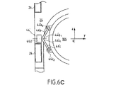
別の解決方法では、側面図である図6B、および図6BのVIB−VIB方向の半断面図である図6Cに示すような変形形態の構成を使用して、後部サスペンション44’が作製される。 In another solution, a rear suspension 44 'is made using a modified configuration as shown in FIG. 6B, which is a side view, and FIG. 6C, which is a half-sectional view in the VIB-VIB direction of FIG. 6B. .
この構成では、後部サスペンション44’は、同様に長手方向の垂直面(xOz)に関して対称であり、左右の対称性を保っている。右側および左側で、後部サスペンション44’は、第1のリンク44’b(または副連接棒)と、第2のリンク44’cと、下部長手方向ビーム46の上面に直接取り付けられた旋回支持部44’d(図6Cおよび図1参照)とを含むアセンブリからそれぞれ形成される。代わりに、旋回リンク支持部44’dを、上部長手方向ビーム26の下面に取り付けることもできる(構成は図示せず)。
In this configuration, the rear suspension 44 'is similarly symmetric about a vertical plane (xOz) in the longitudinal direction, and maintains left-right symmetry. On the right and left sides, the rear suspension 44 'includes a first link 44'b (or secondary connecting rod), a second link 44'c, and a pivot support mounted directly on the upper surface of the lower longitudinal beam 46. 4 '(see FIGS. 6C and 1). Alternatively, a
この場合、より正確には、図6Cに見られるように、第1のリンク44’bは、第2のリンク44’cの上方に位置し、2つのリンク44’b、44’cはそれぞれ、旋回支持部44’dに旋回可能に取り付けられた外端44’b1および44’b2を備え、一方、第1のリンク44’bおよび第2のリンク44’cの内端44’b2および44’c2は、それぞれの弾性的連結を介してターボプロップエンジンの後部106に互いに上下に固定される。
In this case, more precisely, as seen in FIG. 6C, the first link 44'b is located above the second link 44'c, and the two links 44'b, 44'c are respectively includes a pivotally mounted to the
したがって、前部サスペンション42は剛性であるが、上記の弾性的連結により、後部サスペンション44はフレキシブルであることが理解できるであろう。
Thus, it can be seen that the
ターボプロップエンジン100を取り付け、または取り外すために、ホイストが、上部20の上方に配置される。その後、穿孔54内の8本のねじを外し、下部30を取り外すことによって、下部30がキャリア構造10の残りの部分から分離される。
A hoist is placed above the
その後、ターボプロップエンジン100を、前部サスペンション42(タブ42b)および後部サスペンション44(リンク44bおよびリンク44c)から分離してからでないと、ターボプロップエンジンを取り外すことができない。
Thereafter, the
本発明による別の特に有利な解決方法では、図7に示す変形形態を使用して、前部サスペンション42を作製する。
In another particularly advantageous solution according to the invention, a
この場合、固定タブ42aが、下部30の下部アーチ32bに取り付けられている。このようにして、取付け平面Pで、上部20と下部30を相互連結する8本のねじを外し、後部サスペンション44を取り外した後で、ターボプロップエンジン100を、エンジン用の移動クレードルとして働く下部30と一緒に取り出す。
In this case, the fixing
このクレードルの解決方法は、この操作が、下部30が上部20にもはや連結されていない時に行われるので、固定領域42aでタブ42bを中心決めすることをより簡単にする点においても利点があることが理解できるであろう。
This cradle solution also has the advantage that it makes it easier to center the
10 キャリア構造
19 円形開口
20 上部
22 前部アーチ
24 後部アーチ
26 長手方向ビーム
28a、28b 中間アーチ
29 上部エンジンカバーアセンブリ
29a 第1の蝶番付カバー
29b 第2の蝶番付カバー
29c 固定カバー
29d カバー
30 下部
32a、32b、32c、32d 下部アーチ
34 縦通材
39 下部エンジンカバーアセンブリ
40 サスペンション
42 前部サスペンション
44、44’ 後部サスペンション
42a 固定領域
42b タブ
44a 垂直材
44b、44’b 第1のリンク
44c、44’c 第2のリンク
44b1、44’b1 第1のリンク外端
44c1、44’c1 第2のリンク外端
44b2、44’b2 第1のリンク内端
44c2、44’c2 第2のリンク内端
44d、44’d 旋回支持部
50 ピン
52 穴
54 穿孔
100 ターボプロップエンジン
100a ヨーク
102 前部
102a ファン
104 中央部
106 後部
110 フレーム構造
110a ヨーク
P 水平取付け面
10
Claims (15)
前記翼の前記フレーム構造(110)に固定して取り付けられる下向きに開いた上部(20)を含み、該上部(20)が、前記ターボプロップエンジンの前記前部(102)を吊るす前部アーチ(22)と、後部アーチ(24)と、少なくとも前記前部アーチ(22)と前記後部アーチ(24)との間に配置され、かつ前記翼の前記フレーム構造にまで延びる長手方向ビームと(26)を含み、前記長手方向ビーム(26)が、前記前部アーチ(22)と前記後部アーチ(24)を相互連結し、かつ前記翼の前記フレーム構造(110)に固定されるように構成され、前記キャリア構造(10)がさらに、
取り外し可能な上向きに開いた下部(30)を含み、該下部(30)が、少なくとも2本の下部アーチ(32a、32b、32c、32d)を縦通材(34)と共に備え、該縦通材(34)が、前記下部アーチ(32a、32b、32c、32d)を相互連結し、かつ前記長手方向に延び、前記下部(30)が、中心決め/固定手段(50、52、54)によって、上部(20)に取り外し可能に固定され、前記下部および上部(30、20)が、一緒になって前記ターボプロップエンジン(100)を受けるのに適したハウジングを画定し、前記キャリア構造(10)がさらに、
前記ターボプロップエンジンを支持するサスペンション(40)を含むことを特徴とするキャリア構造。 A carrier structure (10) for a turboprop engine (100), said turboprop engine including a front part (102) with a fan (102a), a central part (104) and a rear part (106). And configured to be mounted longitudinally (Ox) below and / or in front of an aircraft wing, the wing comprising a frame structure (110), wherein the carrier structure (10) comprises:
A front arch (20) fixedly mounted to the frame structure (110) of the wing, the top (20) suspending the front (102) of the turboprop engine (102); 22) a rear arch (24); and a longitudinal beam disposed between at least the front arch (22) and the rear arch (24) and extending to the frame structure of the wing (26). Wherein the longitudinal beam (26) interconnects the front arch (22) and the rear arch (24) and is secured to the frame structure (110) of the wing; The carrier structure (10) further comprises:
A removable upwardly open lower portion (30) comprising at least two lower arches (32a, 32b, 32c, 32d) with a stringer (34); (34) interconnects the lower arches (32a, 32b, 32c, 32d) and extends in the longitudinal direction, wherein the lower portion (30) is provided by a centering / fixing means (50, 52, 54) The carrier structure (10), removably secured to an upper portion (20), wherein the lower and upper portions (30, 20) together define a housing suitable for receiving the turboprop engine (100). But also
A carrier structure comprising a suspension (40) for supporting the turboprop engine.
Applications Claiming Priority (1)
| Application Number | Priority Date | Filing Date | Title |
|---|---|---|---|
| FR0302000A FR2851226B1 (en) | 2003-02-19 | 2003-02-19 | CARRIER STRUCTURE FOR A TURBOPROPULSOR AND ASSEMBLY COMPRISING SUCH A CARRIER STRUCTURE |
Publications (1)
| Publication Number | Publication Date |
|---|---|
| JP2004249977A true JP2004249977A (en) | 2004-09-09 |
Family
ID=32732023
Family Applications (1)
| Application Number | Title | Priority Date | Filing Date |
|---|---|---|---|
| JP2004039199A Withdrawn JP2004249977A (en) | 2003-02-19 | 2004-02-17 | Carrier structure in turboprop engine, and assembly having the same |
Country Status (6)
| Country | Link |
|---|---|
| US (1) | US7100869B2 (en) |
| EP (1) | EP1449766A1 (en) |
| JP (1) | JP2004249977A (en) |
| CA (1) | CA2457289C (en) |
| FR (1) | FR2851226B1 (en) |
| RU (1) | RU2004104122A (en) |
Cited By (1)
| Publication number | Priority date | Publication date | Assignee | Title |
|---|---|---|---|---|
| JP2012255437A (en) * | 2011-06-07 | 2012-12-27 | General Electric Co <Ge> | System and method for packing and carrying gas turbine |
Families Citing this family (18)
| Publication number | Priority date | Publication date | Assignee | Title |
|---|---|---|---|---|
| FR2862944B1 (en) * | 2003-12-01 | 2006-02-24 | Airbus France | DEVICE FOR ATTACHING A TURBOPROPULSER UNDER AN AIRCRAFT VESSEL |
| FR2866070B1 (en) * | 2004-02-05 | 2008-12-05 | Snecma Moteurs | TURBOREACTOR WITH HIGH DILUTION RATE |
| US20060032974A1 (en) * | 2004-08-16 | 2006-02-16 | Honeywell International Inc. | Modular installation kit for auxiliary power unit |
| FR2902406B1 (en) * | 2006-06-20 | 2008-07-18 | Airbus France Sas | FITTING FOR SUSPENSION MAT FROM A TURBOMOTEUR TO AN AIRCRAFT WING |
| FR2903665B1 (en) * | 2006-07-11 | 2008-10-10 | Airbus France Sas | AIRCRAFT ENGINE ASSEMBLY COMPRISING A BLOWER HOOD SUPPORT CRADLE MOUNTED ON TWO SEPARATE ELEMENTS |
| FR2916736B1 (en) * | 2007-06-04 | 2009-09-04 | Airbus France Sa | APPARATUS FOR HANDLING AN AIRCRAFT TURBOPROPULSER COMPRISING HYDRAULIC FASTENING MEANS. |
| FR2920409B1 (en) * | 2007-08-27 | 2009-12-18 | Airbus France | BLOWER HOOD SUPPORT ROD MOUNTED ON THE HOOK AND ON THE AIR INTAKE OF THE NACELLE |
| FR2978730B1 (en) * | 2011-08-03 | 2013-09-27 | Airbus Operations Sas | ARTICULATION CRANK FOR BLOWER HOUSINGS SUPPORTED BY THESE HOODS IN CLOSED POSITION |
| BR112016010876B1 (en) * | 2013-11-18 | 2022-02-01 | Lord Corporation | ENGINE FIXING SYSTEM AND FIXING METHOD OF A TURBOPEL ENGINE |
| US9238511B2 (en) | 2014-03-04 | 2016-01-19 | Mra Systems, Inc. | Engine pylon structure |
| DE102015206093A1 (en) * | 2015-04-02 | 2016-10-06 | Rolls-Royce Deutschland Ltd & Co Kg | Engine cowling of an aircraft gas turbine |
| FR3042778B1 (en) * | 2015-10-27 | 2017-11-03 | Snecma | TURBOMACHINE CARRIER STRUCTURE |
| DE102015226546A1 (en) | 2015-12-22 | 2017-06-22 | Rolls-Royce Deutschland Ltd & Co Kg | Engine cowling |
| FR3050436B1 (en) * | 2016-04-26 | 2020-08-14 | Snecma | TURBOMACHINE CARRIER STRUCTURE |
| FR3058704B1 (en) * | 2016-11-14 | 2018-11-16 | Safran Aircraft Engines | SLIPPER BIPARTITE CRADLE FOR TURBOPROPULSEUR |
| FR3088906A1 (en) * | 2018-11-22 | 2020-05-29 | Airbus Operations | Aircraft nacelle comprising a hood with two hinged leaves |
| US11548653B2 (en) * | 2019-10-08 | 2023-01-10 | Rohr, Inc. | Support structure for inner cowls of an aircraft propulsion system |
| FR3118757B1 (en) * | 2021-01-13 | 2023-10-06 | Airbus Operations Sas | FRONT SECONDARY STRUCTURE OF AN AIRCRAFT ATTACHMENT MAST |
Family Cites Families (9)
| Publication number | Priority date | Publication date | Assignee | Title |
|---|---|---|---|---|
| US2958480A (en) * | 1953-06-30 | 1960-11-01 | Saulnier Raymond | Aircraft with low aspect-ratio wing |
| US2944766A (en) * | 1958-03-31 | 1960-07-12 | Boeing Co | Aircraft engine installation |
| US4266741A (en) | 1978-05-22 | 1981-05-12 | The Boeing Company | Mounting apparatus for fan jet engine having mixed flow nozzle installation |
| FR2455547A1 (en) * | 1979-05-02 | 1980-11-28 | Boeing Co | Engine installation for aircraft gas turbine - has cowling linked to upper support by jack-screws permit removal for maintenance |
| GB9119853D0 (en) * | 1991-09-17 | 1991-10-30 | Rolls Royce Plc | Method of and apparatus for removing and replacing a part or parts of a gas turbine engine powerplant |
| US5205513A (en) * | 1991-09-26 | 1993-04-27 | General Electric Company | Method and system for the removal of large turbine engines |
| GB9120658D0 (en) * | 1991-09-27 | 1991-11-06 | Short Brothers Plc | Ducted fan turbine engine |
| WO1996011843A1 (en) * | 1994-10-18 | 1996-04-25 | United Technologies Corporation | Nacelle and mounting arrangement for an aircraft engine |
| US6290173B1 (en) * | 1999-10-28 | 2001-09-18 | Commuter Air Technology, Inc. | Aircraft cracked stack prevention apparatus and method |
-
2003
- 2003-02-19 FR FR0302000A patent/FR2851226B1/en not_active Expired - Lifetime
-
2004
- 2004-02-13 RU RU2004104122/11A patent/RU2004104122A/en not_active Application Discontinuation
- 2004-02-17 JP JP2004039199A patent/JP2004249977A/en not_active Withdrawn
- 2004-02-17 EP EP04290420A patent/EP1449766A1/en not_active Withdrawn
- 2004-02-18 CA CA2457289A patent/CA2457289C/en not_active Expired - Lifetime
- 2004-02-19 US US10/780,639 patent/US7100869B2/en active Active
Cited By (1)
| Publication number | Priority date | Publication date | Assignee | Title |
|---|---|---|---|---|
| JP2012255437A (en) * | 2011-06-07 | 2012-12-27 | General Electric Co <Ge> | System and method for packing and carrying gas turbine |
Also Published As
| Publication number | Publication date |
|---|---|
| US20040227033A1 (en) | 2004-11-18 |
| US7100869B2 (en) | 2006-09-05 |
| FR2851226B1 (en) | 2005-05-20 |
| EP1449766A1 (en) | 2004-08-25 |
| RU2004104122A (en) | 2005-07-27 |
| FR2851226A1 (en) | 2004-08-20 |
| CA2457289C (en) | 2012-04-24 |
| CA2457289A1 (en) | 2004-08-19 |
Similar Documents
| Publication | Publication Date | Title |
|---|---|---|
| JP2004249977A (en) | Carrier structure in turboprop engine, and assembly having the same | |
| JP4729623B2 (en) | Prop for fixing aircraft engine | |
| JP4676982B2 (en) | Aircraft engine unit | |
| CN100506643C (en) | Assembly for aircraft comprising a wing system element as well as an attachment mast | |
| JP4607963B2 (en) | Aircraft engine assembly | |
| JP4699462B2 (en) | Aircraft engine assembly | |
| JP5020943B2 (en) | Pylon suspension attachment for aircraft jet engines | |
| RU2429168C2 (en) | Aircraft power plant with fan housing support assembly mounted on two separate elements | |
| US9032740B2 (en) | Engine assembly for an aircraft comprising attachments for engines offset below on the fan frame | |
| JP5009283B2 (en) | Aircraft engine mounting structure | |
| US7159819B2 (en) | Mounting structure for mounting a turboprop under an aircraft wing | |
| US8251310B2 (en) | Sail wing aircraft which includes an engine mounted on a pylon | |
| JP2009509827A (en) | Aircraft engine assembly comprising an engine and a device for securing the engine | |
| US8733693B2 (en) | Aircraft engine assembly comprising an annular load-transfer structure surrounding the central casing of a turbojet engine | |
| RU2346854C1 (en) | Aircraft rudder fin, and aircraft with such fin | |
| BRPI0616138A2 (en) | Mounting process of an aircraft engine on a rigid structure of an engine mounting bracket | |
| US20110233326A1 (en) | Rear part of an aircraft comprising a structure for supporting engines, extending through the fuselage and connected thereto by at least one connecting rod | |
| CN101959759B (en) | Aircraft engine assembly comprising a turbojet engine with reinforcing structures connecting the fan casing to the central casing | |
| US8366040B2 (en) | Rear part of an aircraft comprising a structure for supporting engines, extending through the fuselage and connected thereto by at least one connecting rod | |
| JP2008545572A (en) | Aircraft engine unit | |
| US7350747B2 (en) | Engine mounting structure under an aircraft wing | |
| US9091210B2 (en) | TEC mount redundant fastening |
Legal Events
| Date | Code | Title | Description |
|---|---|---|---|
| A621 | Written request for application examination |
Free format text: JAPANESE INTERMEDIATE CODE: A621 Effective date: 20050506 |
|
| A761 | Written withdrawal of application |
Free format text: JAPANESE INTERMEDIATE CODE: A761 Effective date: 20060811 |