JP2004249966A - Automatic control method especially usable for maintaining the slippage of tire at optimum level such that tire functions at maximum friction coefficient level - Google Patents
Automatic control method especially usable for maintaining the slippage of tire at optimum level such that tire functions at maximum friction coefficient level Download PDFInfo
- Publication number
- JP2004249966A JP2004249966A JP2003198080A JP2003198080A JP2004249966A JP 2004249966 A JP2004249966 A JP 2004249966A JP 2003198080 A JP2003198080 A JP 2003198080A JP 2003198080 A JP2003198080 A JP 2003198080A JP 2004249966 A JP2004249966 A JP 2004249966A
- Authority
- JP
- Japan
- Prior art keywords
- tire
- value
- function
- equation
- controlling
- Prior art date
- Legal status (The legal status is an assumption and is not a legal conclusion. Google has not performed a legal analysis and makes no representation as to the accuracy of the status listed.)
- Pending
Links
Images


Classifications
-
- G—PHYSICS
- G01—MEASURING; TESTING
- G01M—TESTING STATIC OR DYNAMIC BALANCE OF MACHINES OR STRUCTURES; TESTING OF STRUCTURES OR APPARATUS, NOT OTHERWISE PROVIDED FOR
- G01M17/00—Testing of vehicles
- G01M17/007—Wheeled or endless-tracked vehicles
- G01M17/02—Tyres
-
- B—PERFORMING OPERATIONS; TRANSPORTING
- B60—VEHICLES IN GENERAL
- B60T—VEHICLE BRAKE CONTROL SYSTEMS OR PARTS THEREOF; BRAKE CONTROL SYSTEMS OR PARTS THEREOF, IN GENERAL; ARRANGEMENT OF BRAKING ELEMENTS ON VEHICLES IN GENERAL; PORTABLE DEVICES FOR PREVENTING UNWANTED MOVEMENT OF VEHICLES; VEHICLE MODIFICATIONS TO FACILITATE COOLING OF BRAKES
- B60T8/00—Arrangements for adjusting wheel-braking force to meet varying vehicular or ground-surface conditions, e.g. limiting or varying distribution of braking force
- B60T8/17—Using electrical or electronic regulation means to control braking
- B60T8/172—Determining control parameters used in the regulation, e.g. by calculations involving measured or detected parameters
-
- G—PHYSICS
- G05—CONTROLLING; REGULATING
- G05B—CONTROL OR REGULATING SYSTEMS IN GENERAL; FUNCTIONAL ELEMENTS OF SUCH SYSTEMS; MONITORING OR TESTING ARRANGEMENTS FOR SUCH SYSTEMS OR ELEMENTS
- G05B13/00—Adaptive control systems, i.e. systems automatically adjusting themselves to have a performance which is optimum according to some preassigned criterion
- G05B13/02—Adaptive control systems, i.e. systems automatically adjusting themselves to have a performance which is optimum according to some preassigned criterion electric
- G05B13/0205—Adaptive control systems, i.e. systems automatically adjusting themselves to have a performance which is optimum according to some preassigned criterion electric not using a model or a simulator of the controlled system
- G05B13/024—Adaptive control systems, i.e. systems automatically adjusting themselves to have a performance which is optimum according to some preassigned criterion electric not using a model or a simulator of the controlled system in which a parameter or coefficient is automatically adjusted to optimise the performance
-
- B—PERFORMING OPERATIONS; TRANSPORTING
- B60—VEHICLES IN GENERAL
- B60T—VEHICLE BRAKE CONTROL SYSTEMS OR PARTS THEREOF; BRAKE CONTROL SYSTEMS OR PARTS THEREOF, IN GENERAL; ARRANGEMENT OF BRAKING ELEMENTS ON VEHICLES IN GENERAL; PORTABLE DEVICES FOR PREVENTING UNWANTED MOVEMENT OF VEHICLES; VEHICLE MODIFICATIONS TO FACILITATE COOLING OF BRAKES
- B60T2210/00—Detection or estimation of road or environment conditions; Detection or estimation of road shapes
- B60T2210/10—Detection or estimation of road conditions
- B60T2210/12—Friction
Abstract
Description
【技術分野】
【0001】
本発明は、或るシステムを特定作動点の近くに維持できるようにする自動制御技術に関し、好ましい用途では、本発明はタイヤの試験方法に関する。他の好ましい用途では、本発明は、車両の安定性を制御するシステムに関し、より詳しくは、ブレーキを作動したときにホイールのロックを防止することを目的とした前記制御システムの機能に関する。本発明のシステムは用語「ABS」として広く知られているが、例えば用語「ESP」として広く知られているシステムにおけるように1つのホイールにブレーキを自動的に作動することにより、または他の任意のアクチュエータ(四輪操舵、能動アンチロール…)に作動することにより車両を安定走路上に維持することを目的とする一層精巧な制御システムに関する。
【背景技術】
【0002】
車両の制動は、トレッドが最大摩擦係数値に一致するスリップGで機能するように作られると、一層効率的になることが知られている。最大摩擦係数値はμmaxと呼ばれている。しかしながら、平均的ドライバは、この条件を満たすように制動を制御することはできない。
【0003】
第一のいわゆる「ABS」ブレーキシステムは、タイヤがほぼ最大グリップで振動するようにタイヤを機能させるべく制動力を自動的に変調している(実際に、制動アクチュエータは一般に油圧ジャッキであり、ABSシステムが油圧を変調している)。このことは、再び最大グリップよりほんの僅か小さくなるように制動力を低下させる前にホイールのロック(ホイール回転の突然的停止)を開始させることにより最大グリップを検出できるようにするため、最大グリップを超えることを含むものである。次に制動力は、最大グリップを超えるまで再び自動的に増大され、次に低下される。
【0004】
それにもかかわらず、この方法は、最大摩擦係数値μmaxに一致するGmaxを簡単に超えることを含んでおり、これに対し理想的な状況は、目標スリップを大きく超えることが無く、目標スリップに近付くことである。重要なことは、Gmaxは最大可能スリップ値ではないと慣用的に言われているが、実際には摩擦係数がその最大可能値を有する特定スリップであることに留意することである。
【0005】
制動効率は、最大摩擦係数に一致するスリップの近くでのスリップ変化の細かさによって定まる。効率に言及するとき、本願での唯一の関心事は、緊急制動時に車両のドライバが車両を走行させることができる或る能力を付与するABSシステムの大きい利益は別として、減速の大きさにある。従って、本発明に関しては、制動は、その効率が高いほど制動距離は短くなる。このような制動効率は、制動が最大グリップ係数のレベルにない期間、すなわち過度のスリップの期間および不充分なスリップの期間により損なわれる。
【0006】
第一のいわゆる「ABS」ブレーキシステム(その機能は前述したとおりである)は、種々のタイヤに自動的に適合できるという長所を有していた。この特徴は、例えば、最大摩擦係数での新品タイヤのスリップの方が最大摩擦係数での摩耗タイヤのスリップより大きいことが知られているように、最大摩擦係数での冬期タイヤのスリップが最大摩擦係数での夏季タイヤのスリップよりかなり大きいことが知られているため重要である。残念なことに、この自動制御形式により引起こされる振動は不快であり、ドライバがブレーキペダルに加える押圧力を緩めてしまう効果をもたらすことがある。この世代のブレーキシステムは、例えば米国特許(下記特許文献1参照)に開示されており、該米国特許にはこのようなシステムの改善が説明されている。
【0007】
このシステムは種々のタイヤに適合できる。このために、圧力が段階的に増大される。この場合にはホイールの回転速度の増大が観察され、このため、この圧力を増大させるべきか低下させるべきかが演繹される。すなわち、この自動制御は「適応性」があるが、本来的に振動を発生する。
現在では、車両の安定性制御システムは、最大摩擦係数に一致するように推測された所定の目標スリップを目指して制動力を自動的に変調している。
【0008】
従ってこの場合には、車両ブレーキシステムは、トレッドが、選択された最適スリップレベルで機能する制動力を維持することを目指している。このようなシステムは、各ホイールの回転速度VTyreを連続的に測定する。特定のアルゴリズムでは(例えば下記特許文献2参照)、車両速度VVehicleの評価が得られる。従って、瞬間スリップG=1−VTyre/VVehicleの評価を利用できる。理想的には、この評価されたスリップが最適スリップ以下に維持される限り制動力を低下させてはならないか、自動制動ブースティングの機能が自動的に増大させることもできる(例えば下記特許文献3参照)。最大可能制動力が達成されると、制動圧力は最適スリップGmax、すなわち最大摩擦係数(μmax)に一致するスリップを維持すべく調整される。
【0009】
この維持は、最適スリップを決定することである。欧州特許出願(下記特許文献4参照)では、これは、評価された摩擦係数μおよび同様な評価された車両速度の関数として目指すべき値を与える基準曲線から行なわれる。摩擦係数μの評価は次のように行なわれる。制動が均質路面上で直線的に行なわれるときは、路面上でのタイヤの制動力FXは、ホイールおよびそのブレーキの制動圧力から決定される。全てのタイヤにより加えられる力を知ることにより、従って車両の特徴である負荷伝達、従って各ホイールについての負荷変動を考慮に入れて車両の減速度を計算できる。これから、各タイヤに加えられる垂直荷重FZの近似値を演繹できる。かくして、摩擦係数μ=FX/FZの評価が得られる。評価または測定により対応する横方向力FYが分れば、摩擦係数のより正確な評価が、公式
【数式1】

【0010】
また、前記基準曲線を参照することにより、評価されたスリップGについての基準係数μがどれほどになるかが確立される。現在の評価スリップが目標スリップより低い限り、スリップは、スリップ値が実質的に一致するまで増大される。この第二システムの長所は、第一システムよりも最大スリップに関する振動が小さいことである。
【0011】
残念なことに、この基準曲線は、実験的に決定、従って一定数のタイヤについて予め決定したものであり、これらの使用条件例えば膨張圧力、摩耗レベル等を超えて、車両のタイヤ機器の実際の状態を考慮に入れることはできない。この自動制御原理は、実際には振動を制限または除去するものであるが、制動効率は大幅に損なわれる。なぜならば、事実上本来的に使用されるタイヤは、実際に基準曲線でプログラムされたものとは非常に異なった最大摩擦係数でのスリップを必要とする。
【0012】
【特許文献1】
米国特許第3,980,346号明細書
【特許文献2】
米国特許第5,402,345号明細書
【特許文献3】
米国特許第5,816,666号明細書
【特許文献4】
欧州特許出願EP05303025号明細書
【考案の開示】
【発明が解決しようとする課題】
【0013】
本発明の目的は、例えばタイヤのスリップに適用できる自動制御原理を提案することにより上記欠点を解消し、簡単に上述した第一の既知の方法と同様に自己適応性を有し、かつグリップ限度を超えない最適スリップで第二方法のように少ない振動となることをより確実に目指すことにある。
本発明の一目的は、測定ベンチまたは車両でのできる限り簡単な測定によりかつできる限り少数の測定値により、考察するタイヤの実際の転がり条件に基いて、制動時(または駆動力が作用しているとき)の最大摩擦係数に関連するスリップを予測することにある。
【課題を解決するための手段】
【0014】
本発明は、以下に詳述する観察に基いており、不変量、すなわちタイヤおよび該タイヤが使用される路面の両方から独立した定数をもつパラメータの存在を識別できる。
概していえば、本発明は、以下に説明する特性を呈するあらゆる現象に適用できる調整方法に関する。本発明は、パラメータYが、増大、極値および減少を呈する過程に従ってパラメータXの関数として変化し、かつパラメータYの値を最大値に維持すべくパラメータXの値が自動的に制御される現象の自動制御方法において、
・少なくとも1対の「i」の値についての評価または測定(Xi、Yi)を決定する段階と、
・原点と点(Xi、Yi)とを通る直線の傾斜αiの対応する値を決定する段階と、
・直接計算によりまたは(αi、Xi)との充分な数の対からの回帰により係数Apを計算して、変化曲線αi=f(Xi、Ap)をモデル化する段階と、
・所定の不変量「Invt」を用いて目標値Xmaxを計算する段階とを有することを特徴とする自動制御方法を提案する。
目標値Xmaxは、直接計算または回帰の選択から得られるモデル化公式を用いて計算される。以下に述べるより関心の高い領域は、車両と路面との接触およびこれに含まれる要素およびシステムである。
【0015】
本発明は、移動車両のタイヤの機能の特性パラメータQが、増大、極値および減少を呈する過程に従ってパラメータPの関数として変化し、該パラメータPの値は、パラメータQの値を選択値に維持すべく、タイヤに加えられるトルク、タイヤの舵取り角、タイヤのキャンバ角およびタイヤに加えられる垂直値からなる群から選択される少なくとも1つの要素に作用するコントローラにより直接的または間接的に賦課される構成の路面接触システムにおいて、前記コントローラが、
・少なくとも1対の「i」の値についての評価または測定(δi、Fi)を決定する手段と、
・原点と点(Pi、Qi)とを通る直線の傾斜βiの対応する値を決定する手段と、
・直接計算によりまたは(βi、Pi)との充分な数の対からの回帰により係数Apを計算して、変化曲線βi=f(Pi、Ap)をモデル化する手段と、
・所定の不変量「Invt」を用いて目標値PTargetを計算する手段と、
・PInstantaneousとPTargetとの差の絶対値が所定閾値より大きいときに「能動」モードに変換する手段とを有することを特徴とする路面接触システムを提案する。
【0016】
もちろん、サーボ制御システムより詳しくはサーボ制御装置を有する安全システムで良く知られているように、本発明の使用は、システムのコントローラに、本願で説明するもの以外の手段すなわち目標値PTargetを計算する手段を設けること、例えば冗長をもたせおよび/または或る状況例えば評価しまたは測定した(Pi、Qi)の値で評価される他のストラテジーを用いることを排除するものではない。
コントローラが能動モードに切換わると、コントローラは警告を発しおよび/またはパラメータPに作用して、その値をPTargetに維持し、および/または他の任意の適当なパラメータに作用する。
【0017】
本発明の概念の第一用途はタイヤ試験または路面試験に関する。最大値から充分に離れた状態を維持すると同時に、スリップGの関数としての摩擦係数μの変化曲線が増大する最適スリップGOpt、より詳しくは最大摩擦係数(μmax)に一致するスリップGmaxを信頼性をもって評価できる。
【0018】
本発明は、
・少なくとも1対の「i」値についての評価または測定(Gi、μi)を決定する段階と、
・原点と点(Gi、μi)とを通る直線の傾斜αiの対応する値を決定する段階と、
・直接計算によりまたは(αi、Gi)との充分な数の対からの回帰により係数Apを計算して、変化曲線αi=f(Gi、Ap)をモデル化する段階とを有することを特徴とするタイヤの機能を制御する方法を提案する。
【0019】
摩擦係数は、本発明では上記のように評価され、またはもちろん他の任意の方法例えばタイヤまたはその環境で行なわれる測定から評価される。かくしてスリップに関するタイヤの機能のモデル化(上記変化曲線)が得られ、これは種々の用途を有している。以下に、所定の最適レベルでのスリップの制御に関する非制限的な好ましい用途、より詳しくは例えば、タイヤの最大グリップに対応するスリップの制御に関する用途を説明する。このスリップ制御は、既に強調したように、タイヤにより伝達された長手方向力が制動力である状況およびタイヤにより伝達される長手方向力が駆動力である状況の両方に適用できる。
【0020】
最適スリップGOptの評価が、所定不変量「Invt」を用いることにより、直接計算または選択回帰の選択から得られる公式により決定される。この場合には、直接計算または回帰の選択から得られるモデル化公式を用いて、上記一般的表現を置換することにより計算される。
また本発明は、以下に述べるタイヤ試験方法を提案する。
【0021】
本発明に関連して、トレッドのグリップ特性が、空気タイヤ、または非空気弾性外側ケーシングを取扱うものでも、更にはクローラトラックを取扱うものでも問題ではないことに留意すべきである。用語「トレッド」、「タイヤ」、「外側ケーシング」、「弾性外側ケーシング」、「クローラトラック」または「ホイール」は、均等物であると解釈すべきである。
【0022】
他の好ましい適用例では、本発明は、横方向力の飽和状態近くの機能領域においてタイヤまたは弾性外側ケーシングにより発生される横方向力の分析に関する。
本発明はまた、横方向力(「ドリフトスラスト」ともいう)が最大となるタイヤの横方向スリップ角δ(「ドリフト角」ともいう)の値を予測することを目的とする方法を提案する。タイヤがその最大値に到達し従ってもはやその一次機能(車両の走行を可能にする機能)を遂行できなくなる時点を予測して、タイヤの機能をドリフトスラストFtargetの所定目標値に維持できるようにするか、ドライバに警告を発することが問題である。タイヤの機能を所定目標値に維持するため、必要ならば予防的アクションがとられ、車両速度を低下させて危険な運転状況を回避する(車両がドライバの望むままに旋回しない場合には。事故が起きるであろう)。本発明により提案されるタイヤ機能の制御方法は、横方向力が最大となるタイヤのドリフト角δの値を予測するフェーズを有し、下記の段階すなわち、
・少なくとも1対の「i」の値についての評価または測定(δi、Fi)を決定する段階と、
・原点と点(δi、Fi)とを通る直線の傾斜αiの対応する値を決定する段階と、
・直接計算によりまたは(αi、δi)との充分な数の対からの回帰により係数Apを計算して、変化曲線αi=f(δi、Ap)をモデル化する段階とを有している。
【0023】
かくして、種々の用途を有する、ドリフトに関するタイヤの機能のモデル化(上記変化曲線)が得られる。タイヤのドリフトスラスト能力を適正に使用するためのドリフト角の制御に関する非制限的な好ましい用途を以下に説明する。この場合、この方法は更に、次の段階すなわち、
・所定不変量「Invt」を用いてドリフト角δOptの値を計算する段階と、
・ドリフト角δがδOptに接近すると警告信号を発生する段階を有している。
・ドリフト角δがδOptに近付いたときに警告信号を発生する、
【0024】
タイヤの試験方法に加えて、本発明はまた、車両の安定性を制御するシステムに関する。このことは、制動力が加えられたときにホイールのロックを防止することを目的とする用語「ABS」として広く知られた機能、または物理的に可能な限度まで制動力を自動的に増大させることを目的とした機能の両方を意味する。また本発明の車両の安定性制御システムは、1つのホイールのブレーキに自動的かつ選択的に作用することにより、および/または1つまたは幾つかのホイールにまたは車両の挙動に影響を与える他の任意のアクチュエータに自動的かつ選択的に作用することにより、車両を安定走路上に維持することを目的とする車両の安定性制御システムの一層精巧な態様を意味する。
【発明を実施するための最良の形態】
【0025】
以下、添付図面を参照して本発明をより詳細に説明する。
本発明は、次の観察に基いている。
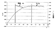
図4は、2バールの膨張圧力で種々の路面上で試験した同一のMICHELIN XH1 195/65−15タイヤについてのスリップの関数としての摩擦係数μの種々の曲線を示すものである。図5は、種々のタイヤ、種々の路面、および速度、タイヤ荷重等に関する種々の試験条件に対応する非常に多くの試験についての摩擦係数μmaxの位置および対応スリップを示すものである。これらの値は広く拡散しているため、このようなアプローチを用いてグリップの物理的現象を把握できるようにする回帰(regression)を見出すことは、架空でない限り困難であることは理解されよう。
従って、本件出願人は、以下に述べる方法で研究を行なってきた。G=GmaxおよびG=Gmax/2(「50%」で示した)について計算した商の分析も行なわれた(図6参照)。
【0026】
図7は、平均値を決定する前の約400回の試験すなわち全部で3000個の測定値についての比μ/Gat 50% of maxの関数として比μmax/Gmaxの値を示すものである。図7は、変えることができる多くの路面条件、種々のタイヤおよび試験条件(荷重、速度、圧力)を反映している。これにより、上記不変量(Invariant)「Invt」の卓越した実験的確認についての理解が得られる。
【0027】
考察されるタイヤおよび試験条件の如何にかかわらず、次式を満たすことが判明している。
【数式2】
【0028】
次に、曲線μ(G)(図8参照)の平均傾斜が考察される。この傾斜をαとすれば、次式が得られる。
【数式3】
![]()
【数式4】
![]()
【数式5】
これから、Gmaxが演繹され、これは、車両のブレーキシステムコントローラが目指す目標であり、本発明によれば次式が得られる。
【数式6】
【0030】
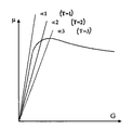
上記観察はスリップの関数としての摩擦係数の変化曲線に基いているので、同様な特性曲線を有する他の物理量の関数として1つのパラメータの変化を含むあらゆる現象に対して有効性が維持される。従って本発明は、Y(X)の曲線が図10に示す過程をたどるようなパラメータYが存在するときにパラメータXに対して有効であるか、並進(translation)、相似変換、反転(reversal)およびこれらの同じ変換等の簡単な変換の後にこのような曲線となる任意の変化現象に対して有効な自動制御方法を提案する(図10に示す曲線と同じ過程に戻る前に遂行される並進と反転との組合せを示す図11を参照されたい)。
【0031】
また、上記式(2)は線形回帰が、スリップGの関数としての摩擦係数μの変化の進化(evolution)を非常に正確にモデル化できることを示しているが、最も適当な回帰形式についての賢明な選択がなされれば、ここに提案される手順の精度を向上できることが判明している。かくして、回帰の適当な形式を選択することは本発明に包含され、このことは、一般に、以下に説明する調整手順を提案する。
【0032】
従って本発明は、次の特性を有するあらゆる物理的現象に適用される。
・測定または評価された制御パラメータX。
・次の形態すなわち、最大値Ymaxの存在;Ymaxより非常に小さいY(0)(ファクタ10は少なくとも値Y(0)とYmaxとを分離しなくてはならず、Y(X)はXmaxまで連続的に増大する)の所与の環境に対して、Xの値に基いた測定または評価されたパラメータY。
【0033】
この目的は、低いXの値に向けて出発するプロセスY(X)では、できる限り早くYの値を最大にすることである。ここでは、実際の測定(または評価)(一般に、入力Xおよび出力Yでのノイズにより影響を受ける)に関連して、特に、最大値を演繹的に知ることなくかつ最大値を超える必要なく最大値を得ることを可能にするロバストアルゴリズムが提案されている。この方法は絶対値を必要としない。
【0034】
以下の観察が使用された。すなわち、
(Xmax)の最大値での割線(secant)と、X=Xmax/2での割線との間には下回る関係が存在する。一般的な関係は一定の商(不変量)である。この不変量は、特定現象へのこの方法の各適用時に決定されなくてはならない。
【0035】
不変量を決定する実用的な非制限的方法は次の通りである。すなわち、
【数式7】
【0036】
0<Invt≦1は常に維持される。考察している物理的現象での固有不変量として上記した「Invt」は、実際に、特定分野へのあらゆる適用を行なうため、特定システムの洗練での調節変数を提供することによりアルゴリズムを微細に調節することを可能にする自由度となる。
【0037】
一般に、第一近似として次式が考察される。
【数式8】
【0038】
Xの関数としての割線の関係についての他の回帰形式を使用でき、この場合には、最大値Xmaxの分析公式または近似公式を得るのに、対応システム(最大値での割線の値を半値にリンクさせる等式:〔Eq〕)を解くことが賢明である。Yについてのスケール誤差(例えば、Yは、50%だけ系統的に課題評価される)は、Xmaxの予測値を変化させず、これにより、スケール効果に非常に有利な低い感度を与える。
この意図は、物理的曲線の不変量に基いて、利用できる全ての関連情報を用いることにより、最大値に向かって「上昇」する間に付随する「測定」により最大値を演繹することである。
【0039】
図1は、提案するアルゴリズムを示し、この主な段階は次の通りである。
1.実際の可能性に従って、測定または評価による点(Xi、Yi)の獲得。少なくとも2つの点を獲得するのが賢明である。Xiは非ゼロを表し、ここでは、小さ過ぎて不適当な値を無くすべく最小閾値が賦課される。
2.前の値を用いた割線の計算。割線の値は、αi=Xi/Yiを直接計算するか、ノイズを無くすためi以下の全ての添字点を考慮して、適当な回帰、例えば、
【数式9】
【0040】
3.対(αi、Xi)を用いた回帰の計算。回帰は、対象とする物理的現象およびノイズレベルに従って洗練しなければならないが、測定または評価された充分な数「n」の点(一般には、5つの点)から計算される。
・線形回帰の場合
【数式10】
【数式11】
【0041】
4.次に、Xmaxの評価が計算される。
・線形回帰の場合には、α=ALin・X+BLinを用いて次式が得られる。
【数式13】
【数式14】
5.この方法の特別な使用に従ってXmaxを知ることができると、殆どの適当なパラメータが調節される。例えば、パラメータXの値は、その値をXmaxに維持すべく自動的に制御される。
【0043】
6.必ずしも有効といえないかもしれないが、Ymaxの評価を計算するまで続行できる。
・線形回帰の場合には、更に、Ymaxが次のように決定される。ここで、Ycoeff_linは、実験的に調節される係数である。
【数式15】
【数式16】
線形:
【数式17】
【数式18】
【0044】
本発明の幾つかの可能適用例について以下に詳細に審査する。以下の記載は限定的なものでも排他的なものでもない。
【実施例1】
【0045】
例1:タイヤの機能の、或る摩擦係数例えば最大摩擦係数μ max での自動維持
長手方向グリップμ(G)に関する適用例に戻って説明する。この場合には、本願明細書の冒頭部分で既に説明したように、Yはタイヤの摩擦係数μ、すなわち、長手方向力(例えば駆動力または制動力)を、加えられた垂直力(すなわちタイヤに加えられた荷重)で割った商であり、XはタイヤのスリップGの比である(タイヤの速度と車両の速度との間にスリップが存在しないとき、すなわちタイヤが自由に転がるときはG=0%であり、タイヤの回転がロックされたときはG=100%である)。一般に、環境(路面の性質(アスファルトまたはコンクリート)、ドライまたはウェット(水レベル)、温度、およびタイヤの摩耗レベル)に基いて、スリップGの関数としてのμの値は非常に大きく変化する(μは、氷上で約0.15、ドライ路面上で約1.2である)。図4を参照すると、ここには、或る荷重および速度条件で測定された新しいXH1 195/65R15タイヤについてのスリップGの関数としてのμの幾つかの曲線が示されている。
【0046】
本発明により提案されるタイヤの機能を制御する方法は、測定または車両への適用であるか否かを問わず、特に、スリップGを自動制御して、所定の最適値GOptに維持することができる。前記所定スリップGOptは、より詳しくは、非制限的態様で、摩擦係数の所定値が実質的に値μmaxに一致するように選択される。この場合、これを特定最適値Gmaxと名付けることが一般的に行なわれている。
【0047】
このタイヤの最大値の位置は路面に基いて変化することが判明している。また、いかなる一致(unity)も存在しないことがある。達成される同じ最大レベルについて、2つの一致するスリップを得ることができる。それにもかかわらず、これらの曲線が共有する1つの不変量「Invt」が存在する。
【0048】
不変量を決定する方程式を、スリップの関数として摩擦係数の分析の場合に適用することにより、不変量は、1より小さい正の値をもつpを用いて、より詳しくは次式のように計算される。
【数式19】
【0049】
かくして次式が得られる。
【数式20】
データを、他のパラメータY(例えば摩擦係数μmax)の最大値に一致するパラメータX(例えばスリップG)の第一値で、および第一値の50%(例えば上記スリップの50%)に一致する第二値で処理することにより、1つの不変量「Invt」が導入された。50%での処理の選択は任意であること、および処理が摩擦係数μmaxに一致するスリップの25%または75%で遂行される場合には不変量が得られることも判明している。従ってこの選択は、特に、各特定用途への実験的フェーズの一部である。
【0051】
次に、傾斜αiを決定することが賢明である。これはαi=μi/Giの直接計算により行なわれ、適当な回帰(例えば、次式のような線形回帰)が使用される。
【数式21】
【数式22】
次に、線形回帰が使用される場合には、α=ALin・G+BLinを用いて、GOptが下記のように計算される。
【数式23】
【数式24】
割線の線形アプローチにより決定される下記表は、2バールの膨張圧力により種々の路面で試験されたMICHELIN XH1 195/65−15タイヤでの実際の測定値からの最大スリップの計算を示すものである。
【0054】
【表1】
さもなくば、2つの特定係数Ap、AおよびBは、下記の指数回帰により計算される。
【数式25】
次に、指数回帰が使用される場合には、GOptが下記のようにして計算される。
【数式27】
【数式28】
![]()
【0057】
本願に提案する方法は、摩擦係数の変化のみが取扱われ、その絶対値は取扱われないので自己適応性を有しかつ非常にロバスト(robust)である。また、ノイズに対する感度が非常に低いことも判明している。
【0058】
スリップの関数としてタイヤの長手方向グリップに適用される上記方法に固有の性質は、タイヤの試験を行なうのに非常に適しており、シミュレーションを構成するのに一層てきしている。また、上記固有の性質は、車両のブレーキシステムでのタイヤのグリップのモデル化に最も適している。
【0059】
タイヤ工業界では、本発明はタイヤの試験および測定に適用される。従って本発明の一態様は、スリップに関してタイヤを試験する方法であり、下記の段階すなわち、
・選択された路面(路面は、道路、試験トラック、平トラックまたはホイールを備えた試験機で構成できる)上でタイヤを動転させる段階と、
・所定荷重FZ1をタイヤに加える段階と、
・タイヤがグリップ限度以下に維持されるようにして、所定スリップをタイヤに付与(タイヤと路面との間の相対速度で作動)する段階と、
・タイヤの長手方向応力FX1を測定または評価する段階と、
・摩擦係数μ1=FX1/FZ1の値を計算する段階と、
・前の段階を反復して、少なくとも1つの他の応力FX1/FZ1の対「i」についての摩擦係数μiの少なくとも1つの他の値「i」を計算しかつ関連スリップGiを測定する段階と、
・計算した摩擦係数の各値について、原点と点(Gi、μi)とを通る直線の傾斜αiを決定する段階と、
・変化曲線αi=f(Gi、Ap)をモデル化すべく、直接計算によりまたは(αi、Gi)との充分な数の対からの適当な回帰により係数Apを計算する段階と、
・所定不変量「Invt」を使用して、所定摩擦係数値GOptが得られるようにする最適スリップを計算する段階と、
からなる。
【0060】
もちろん、理解されようが、不変量は、この試験方法を実験的に洗練することにより選択される。例えば洗練中に不変量の第一値を選択するには、1より小さい正の値をもつpを使用して、次式のように不変量を決定するのが有利である。
【数式29】
前述と同様にして、2つの特定係数Apおよび係数AおよびBは、線形回帰および指数回帰からなる群から選択された回帰により計算できる。
この場合にも、pの値として、0.25〜0.75の間の値、一般には0.5を採用できる。
【実施例2】
【0062】
例2:制御時または駆動力を受けているときの最適スリップの決定
車両のブレーキシステムは効率的であるが、それは製造業者が選択する一定数のタイヤ最適であること、および車両に実際に装着されたタイヤには適用できないことは知られている。より詳しくは、良く知られているように、特に所与の路面上の力Fxでのグリップおよびスリップにおいて極めて異なる挙動を呈する冬期タイヤには適用できない。従って、車両のブレーキシステムの効率は、車両に実際に使用されているタイヤに自動的に適用できるならば改善される。
【0063】
従って本発明は、路面上を走行することを意図したタイヤにスリップを伝達する手段と、該スリップ(ホイールの速度に作用)を変調する手段と、摩擦係数μの所定値に一致する少なくともパラメータスリップGOptを用いるコントローラとを有する車両の安定性を制御するシステムにおいて、前記コントローラは、下記のように、すなわち、
・グリップのいかなる損失も存在しない条件で、スリップGiの少なくとも2つの異なるレベル「i」でスリップをタイヤに伝達する手段を付勢する度毎に、摩擦係数μiの値を決定し、
・原点と点(Gi、μi)とを通る直線の傾斜αiを決定し、
・充分な数の点(αi、Gi)の対から、直接計算によりまたは適当な回帰より詳しくは線形回帰および指数回帰からなる群から選択された回帰により係数Apを計算して、変化曲線αi=f(Gi、Ap)をモデル化し、
・所定の不変量「Invt」を用いて最適スリップGOptを計算し、
・長手方向の力をタイヤに伝達する手段に作用して、スリップを最大値GOptに維持する、
ことにより前記パラメータ(単一または複数)を計算する手段を有していることを特徴とする車両の安定性制御システムに拡大される。
【0064】
もちろん、現在の一般的な設計による内燃機関を備えた車両の場合には、タイヤにスリップを伝達する手段は、本質的に制動状況でのブレーキでありかつ本質的に駆動力が作用するエンジン管理システムである。当業者ならば、本発明を他の車両設計例えば電気自動車に適用することは容易であろう。
この場合にも、前述のように、本発明は、システムのコントローラが、本願に説明する手段に加えて、他のスリップ制御ストラテジーを具現する他のプログラムによりローディングされることを排除しない。このことは、或る状況でへ、例えばスリップをタイヤに伝達する手段の任意の特別な付勢時に点(Gi、μi)の値を評価または測定する場合に好ましいものとなる。
【0065】
より詳しくは、不変量を決定する好ましいアプローチは次の通りであり、この場合にも0.25〜0.75の間の値、一般には0.5を有するpを使用する。
【数式30】
本発明の特定実施形態では、スリップを変調するデバイスがブレーキ制御に作用する。本発明の他の実施形態では、スリップを変調するデバイスがホイールでの駆動トルクに作用する。
【0067】
車両のブレーキシステムに特に有効な新しいアルゴリズムであって、上記不変量「Invt」に基いて摩擦係数μmaxの位置を決定できるようにするアルゴリズムを創出することが提案される。理解されようが、このようなシステムは摩擦係数μmaxの評価を行い、次に、基準曲線により最適スリップを選択する。これらの段階を下記のもので置換することを提案する。
【0068】
この原理の実施は、ABSコントローラに幾つかの修正を必要とする。すなわち、
・計算周波数は40Hz以上であるのが好ましい。
・信頼できる(代表的な)目標を計算するための充分に多数の位置を獲得すべく、ABSのトリガリングを調整することが賢明である。
・スリップでの測定点を非常に少数(例えば、1%以下のスリップに一致)に減少させることが有利である。
・スリップGの非常に高い精度が得られるようにするには、特殊手段を用いるがホイール速度データ処理(GPS、路面観察…)を行わないで車両速度を獲得するのが有利である。
【0069】
上記提案の新しいアルゴリズムにより、車両のブレーキシステムの効率は、車両に現実的に使用できる全範囲のタイヤに亘って非常に優れたものとなる。
開発された新しいアルゴリズムは、システムを、いかなる付加センサおよびタイヤトレッドの測定をも必要とせず、あらゆる種類のタイヤに自動的に適合させることができる。また、このアルゴリズムは、所与の車両に選択されるタイヤの種類に対して微調節の必要性を無くすことができる。
上記のように、本発明の方法は、測定値についてだけでなく、評価値についても結果を得ることができる。実際の(評価したものではない)力FX、FyおよびFZに関する情報は、より正確な目標をもつこと、および/または賞賛に価するチェックを行なって、車両のブレーキシステムの信頼性を向上させることができる。
【実施例3】
【0070】
例3:発生したドリフトおよび横方向力F y (ドリフトスラストとも呼ばれる)に関するタイヤの機能の分析
他の適用例を以下に説明する。この適用例は、タイヤのドリフト角δ(ホイールの平面の路面上の突出部と路面上での車両のベクトル速度とのなす角度)の関数として横方向力Fyを特徴付けることを含んでいる。最適ドリフト角δOpt例えばタイヤが最大横方向力Fyを発生するドリフト角は予め決定でき、横方向力Fymaxも予め決定できる。最大横方向力は、例えば、関連する車両の平衡にとって重要なものである。これは、この機能形態でのタイヤの試験が本発明の好ましい適用であることによる。例えばこの場合には、本発明は、横方向力が最大となりかつ警告信号が発生されるタイヤのドリフト角δの値を予測するフェーズを有する、タイヤの機能を制御する方法、またはドリフト角δがδOptを維持するように自動的に制御される方法、または警告信号が発生される場合にドリフト角δが減少される方法の実施を可能にする。
【0071】
横方向Fyとドリフト角δとの関係は、前のセクションで述べたμとGと同じ形式である。従って、例えば不変量は下記のように決定できる。
【数式31】
上記のように、pに関する限り、その値は0.25〜0.75の間、例えば0.5であるのが好ましく、pの値の選択の結果に関して上記一般的表示を参照されたい。この正確な場合には、大きさ「Invt」は顕著に高いものとなる。値が小さくなり過ぎて、割線の決定を妨げることを回避するため、2°の最小ドリフト角閾値を維持すると同時に0.8の値が得られた。
【0073】
図3は、ドリフト角に対するドリフトスラストの変化、および/または原点と、同じドリフト角での前の曲線の点とを通る割線の同じドリフト角での変化を示す曲線である。キャンバをもたず、5000ニュートンの荷重を受けるMichelin Primacy 235/55R17タイヤでは、本発明の方法により評価された最大ドリフト角は5.5°、および最大評価ドリフトスラストは5935ニュートンである。
【0074】
次に、傾斜αiを決定するのが賢明である。これは、αi=Fi/δを直接計算することにより行なわれ、または適当な回帰例えば下記のような線形回帰が使用される。
【数式32】
【数式33】
線形回帰が使用される場合には、α=ALin・δ+BLinを用いて、δOptが下記のように計算される。
【数式34】
アルゴリズムを適用することにより、横方向力(Fy)が約6°のドリフト角δでその最大値を達成するように予め定められている。タイヤがスリップを開始する前に横方向スラストを生じさせる可能性はもはや大きくないことを知ることができるので、この情報は価値あるものである(横方向スラストが飽和すると車両が旋回することが防止される)。
必要ならば、下記のように、δOptに一致するFの値が決定されるまで続けることができる。ここで、Fcoeff_linは指数的に調節される係数である。
【数式35】
![]()
さもなくば、2つの特定係数Ap、係数AおよびBは、「n」個の測定点または評価点に適用される下記の指数回帰により計算される。
【数式36】
次に、指数回帰が使用される場合には、GOptが下記のようにして計算される。
【数式38】
【数式39】
【0079】
例3a:タイヤの測定または試験のための使用
タイヤ工業界では、本発明は、タイヤの試験または測定に適用される。従って本発明の他の態様では、ドリフトに関してタイヤを試験する方法は下記段階、すなわち
・路面上でタイヤを動転させる段階と、
・所定荷重FZ1をタイヤに加える段階と、
・タイヤがグリップ限度以下に維持されるようにして、所定ドリフト角δiをタイヤに付与しかつ前記ドリフト角δiに一致するドリフトスラストFiを測定または評価する段階と、
・前の段階を反復して、少なくとも1つの他の対(δi、Fi)の値「i」を計算する段階と、
・原点と点(Gi、Fi)とを通る直線の傾斜αiの対応値を決定する段階と、
・変化曲線αi=f(δi、Ap)をモデル化すべく、直接計算によりまたは(αi、δi)との充分な数の対からの適当な回帰により係数Apを計算する段階と、
・所定不変量「Invt」を使用して、ドリフト角δOptの値を計算する段階と、
からなる。
【0080】
同様に、不変量は、この試験方法を指数的に洗練することにより選択される。例えば、この洗練中に不変量の第一値を選択するには、1より小さい正の値をもつpを用いて、不変量を下記のように決定するのが有利である。
【数式40】
前記と同様にして、2つの特定係数Apおよび係数AおよびBは、線形回帰および指数回帰からなる群から選択された回帰により計算される。
この場合にも、pの値として、0.25〜0.75の間の値、一般には0.5を採用できる。
【実施例5】
【0082】
例3b:湾曲路上での車両の最大可能ドリフトの決定
タイヤが装着された車両の安定性への本発明の適用において、本発明により提案されるタイヤの機能を制御する方法は、タイヤのドリフト角δ(ドリフト角δは、ホイールの平面の路面上の突出と路面上での車両のベクトル速度とのなす角度であう)の値を予測するフェーズを有し、このフェーズでは横方向力が最大になり、ドリフトスラストに関してタイヤの最大ポテンシャルへの非常に近いアプローチがなされた場合にドライバに警告を与えることができ、或いは、警告信号が発生されたときに車両の安定性を自動的に制御するシステムに一体化されたより進歩した態様では、車両速度が自動的に制限または低下される。
【0083】
本発明は能動車両(後車軸および/または前車軸の能動ステアリング機構、またはボディロールの能動制御装置、または車両の横方向平衡に作用する任意のシステムを備えており、従って、タイヤに賦課される横方向スラストに作用する車両)にも適用できる。すなわち、車両の横方向安定性を自動制御するシステムからの命令に従って反応することもできる。
【0084】
この点に関し、本発明は、路面上を走行することを意図した少なくとも1つのタイヤを有する車両の安定性を制御するシステムにも拡大される。車両には、車両に使用される技術に基いて、車両のドライバにより該ドライバの制御手段に伝達される命令に基いて、およびタイヤの機能をドリフトスラストFtargetの所定の目標値に維持することを目的とする毛色コントローラにより与えられる命令に基いて、すなわち各車軸のタイヤのドリフト角に直接的または間接的に基いて、選択されたパラメータ(以下、パラメータ「λ」と呼ぶ)を制御するシステムが設けられている(例えば、前記パラメータ「λ」は能動舵取りを行なうための前後のホイールのステアリングであり、または前記パラメータ「λ」は能動アンチロールのためのボディロールであり、またはパラメータ「λ」は制動アクチュエータを介して安定制御を行なうための制動力である)。走路コントローラは、ドリフトスラストFtargetの最大値に一致するドリフト角の少なくとも1つの最適値δOptを使用し、前記コントローラは、下記の作動を遂行する手段を有している(前後の車軸が同じでなく、左右のタイヤが異なっている各車軸での作動が好ましいが、本発明の原理は、1つのタイヤのみに適用できるものであるが、当業者ならば全てのタイヤに対処させることができるであろう)。
【0085】
・ドリフト角の少なくとも2つの異なるレベル「i」で前記パラメータ「λ」を制御するシステムを付勢する度毎に、FYiおよび関連するドリフト角δiの種々の値を記録し、
・原点と点(δi、FYi)とを通る直線の傾斜αiを決定し、
・直接計算によりまたは(αi、δi)との充分な数の対からの適当な回帰により、より詳しくは線形回帰および指数回帰からなる群から選択された回帰により係数Apを計算して、変化曲線αi=f(δi、Ap)をモデル化し、
・所定の不変量「Invt」を用いて、ドリフトスラストFtargetの最大値に関連するタイヤドリフト角の最適ドリフト角の値δOptを計算し、
・ドリフト角δがδOptに近付いたときに警告信号を発生する。
【0086】
前述のように、最適ドリフト角δは、直接計算または回帰の選択から得られるモデル化公式(上記変化曲線)により計算される。より詳しくは、不変量を決定する好ましいアプローチは、0.25〜0.75(一般的に0.5)の間の値をもつpを使用する次式である。
【数式41】
本発明の特定の実施形態では、警告信号が発生されると、選択されたパラメータを制御するシステムが付勢され、ドリフト角δを最適値δOptに維持する。他の実施形態では、警告信号が発生されると、車両速度が制限または減速される。
【0088】
強調すべき重要なことは、スリップの関数として摩擦係数を用いることと、ドリフト角の関数としてドリフトスラストを用いることとは相反的なものではないということである。特に、これらの2つの態様を同時に使用することは、車両の走路の自動制御システムにとって有利なことである。かくして、本発明の一態様は、タイヤの前記機能を摩擦係数μの所定値に維持することを目的として、所与の形状のタイヤの機能を自動的に制御する方法に関し、下記の段階すなわち、
・複数対の「i」の値についての評価または測定(Gi、μi)を決定する段階と、
・前記タイヤの固有の物理的特性および存在する実際の機能的形状の関数として、タイヤGOptの最適スリップの評価を計算する段階と、
・GinstantaneousとGOptとの差の関数として形状を自動的に制御する段階と
を有している。
【実施例6】
【0089】
例4:(金属試験片での引張り試験)
他の適用例として、伸びの関数としての引張り応力を受ける試験片の伸びの分析について留意されたい(破断直前に試験を停止させることにより試験片の突然破断を回避するため)。この場合、パラメータXは伸び、最大伸びは力の測定および応力付与開始時の伸びから評価され、かつ試験は最大伸びの近くでかつ最大伸びより小さい選択された伸びが生じた時点で停止される。また、最大可能力も評価される。
【図面の簡単な説明】
【0090】
【図1】本発明による自動制御手順を示すブロック図である。
【図2】スリップに対する摩擦係数の変化を示す曲線と、原点と前記スリップと同じスリップでの前の曲線の点とを通る割線の同じスリップでの変化を示す曲線とを示すグラフである。
【図3】ドリフト角に対するドリフトスラストの変化を示す曲線と、原点と前記ドリフト角と同じドリフト角での前の曲線の点とを通る割線の同じドリフト角での変化を示す曲線とを示すグラフである。
【図4】種々の試験条件下での同一タイヤのスリップに関する摩擦係数の変化についてプロットした幾つかの曲線を示すグラフである。
【図5】多数のタイヤおよび種々の試験条件下での摩擦係数μmaxおよびの位置および関連するスリップGmaxの位置を示すグラフである。
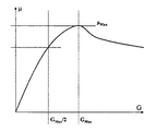
【図6】スリップに対する摩擦係数の変化を示す一般的な概略曲線であり、このグラフには2つの特別な点すなわち摩擦係数μmaxおよびこの関連スリップGmaxが印されており、摩擦係数μ50%に対応する慣用点は、Gmax/2で慣用的に印されたスリップGmaxを50%上回っている。
【図7】多数のタイヤおよび種々の試験条件下での摩擦係数μmaxに関連するスリップについての摩擦係数μmaxの商μ/G(Gmaxでの商)、および摩擦係数μmaxに関連するスリップの50%のスリップについての摩擦係数の商μ/G(Gmaxの50%での商)に対応する縦軸上の点の位置を示すグラフである。
【図8】スリップに対する摩擦係数の変化を示す一般的な概略曲線および原点を通る割線の過程および3つの特定点のスリップの曲線を示すグラフである。
【図9】原点と、同じスリップでの摩擦係数の変化曲線の点とを通る割線の傾斜のスリップの関数としての線形変化を示す一般的な概略曲線のグラフである。
【図10】Xに対するYの変化を含む現象への一般的な適用曲線であって、特定XについてのYの最大値およびYの最大値での単調上昇を呈する曲線を示すグラフである。
【図11】基本的には前の変化現象と同様な他の変化現象に一般的に適用した場合の曲線を示すグラフである。【Technical field】
[0001]
The present invention relates to an automatic control technique that enables a system to be kept close to a specific operating point, and in a preferred application, the present invention relates to a method for testing a tire. In another preferred application, the invention relates to a system for controlling the stability of a vehicle, and more particularly to the function of said control system for the purpose of preventing wheel locking when a brake is applied. The system of the present invention is widely known as the term "ABS", but by automatically applying a brake to one wheel, as in the system widely known as the term "ESP", or any other More specifically, the present invention relates to a more sophisticated control system for maintaining a vehicle on a stable runway by operating the actuator (four-wheel steering, active anti-roll ...).
[Background Art]
[0002]
It is known that vehicle braking becomes more efficient when the tread is made to function with a slip G that matches the maximum coefficient of friction value. The maximum friction coefficient value is μmaxis called. However, the average driver cannot control the braking to satisfy this condition.
[0003]
The first so-called "ABS" braking system automatically modulates the braking force to make the tire function so that it oscillates at near maximum grip (in fact, the braking actuator is typically a hydraulic jack and ABS The system is modulating the oil pressure). This is because the maximum grip can be detected by initiating the locking of the wheel (sudden stop of wheel rotation) before reducing the braking force to only slightly less than the maximum grip again. Including exceeding. The braking force is then automatically increased again until the maximum grip is exceeded, and then reduced.
[0004]
Nevertheless, the method has a maximum coefficient of friction value μmaxG that matchesmaxIs simply exceeded, whereas the ideal situation is to approach the target slip without significantly exceeding the target slip. The important thing is GmaxIt is customary to say that is not the maximum possible slip value, but in fact the coefficient of friction is the specific slip with that maximum possible value.
[0005]
The braking efficiency is determined by the fineness of the slip change near the slip which corresponds to the maximum coefficient of friction. When referring to efficiency, the only concern here is the magnitude of deceleration, apart from the great benefit of an ABS system that gives the vehicle driver some ability to run the vehicle during emergency braking. . Thus, in the context of the present invention, the higher the efficiency of braking, the shorter the braking distance. Such braking efficiency is impaired during periods when braking is not at the level of the maximum grip factor, ie during periods of excessive slip and insufficient slip.
[0006]
The first so-called "ABS" brake system, whose function is as described above, had the advantage that it could automatically adapt to various tires. This feature is, for example, that the slip of a winter tire at the maximum friction coefficient is the maximum friction coefficient, as it is known that the slip of a new tire at the maximum This is important because it is known to be significantly greater than the summer tire slip by the factor. Unfortunately, the vibrations caused by this type of automatic control are unpleasant and can have the effect of reducing the pressure applied by the driver to the brake pedal. A brake system of this generation is disclosed, for example, in U.S. Pat.
[0007]
This system can be adapted to various tires. To this end, the pressure is increased stepwise. In this case, an increase in the rotation speed of the wheel is observed, so that it is deduced whether this pressure should be increased or decreased. That is, this automatic control has "adaptation", but inherently generates vibration.
Currently, vehicle stability control systems automatically modulate the braking force to a predetermined target slip that is estimated to match the maximum coefficient of friction.
[0008]
Thus, in this case, the vehicle braking system seeks to maintain the braking force at which the tread functions at the selected optimum slip level. Such a system is based on the rotational speed V of each wheel.TireIs measured continuously. In a specific algorithm (for example, see
[0009]
This maintenance is to determine the optimal slip. In the European patent application (US Pat. No. 6,037,045) this is done from a reference curve which gives the value to be aimed as a function of the estimated coefficient of friction μ and similarly the estimated vehicle speed. The evaluation of the friction coefficient μ is performed as follows. When braking is performed linearly on a homogeneous road surface, the braking force F of the tire on the road surfaceXIs determined from the braking pressure of the wheel and its brake. By knowing the forces exerted by all the tires, the deceleration of the vehicle can be calculated taking into account the load transfer characteristic of the vehicle and thus the load fluctuations for each wheel. From now on, the vertical load F applied to each tireZCan be deduced. Thus, the coefficient of friction μ = FX/ FZIs obtained. Lateral force F corresponding to the evaluation or measurementY, A more accurate assessment of the coefficient of friction is
[Formula 1]
[0010]
Also, by referring to the reference curve, it is established how much the reference coefficient μ for the evaluated slip G will be. As long as the current estimated slip is lower than the target slip, the slip is increased until the slip values substantially match. The advantage of this second system is that it has less vibration for maximum slip than the first system.
[0011]
Unfortunately, this reference curve is experimentally determined and therefore predetermined for a certain number of tires and, beyond these conditions of use, e.g. The state cannot be taken into account. Although this automatic control principle actually limits or eliminates vibration, braking efficiency is greatly impaired. Because, in essence, the tires that are inherently used require slip at a maximum coefficient of friction that is very different from that actually programmed in the reference curve.
[0012]
[Patent Document 1]
U.S. Pat. No. 3,980,346
[Patent Document 2]
U.S. Pat. No. 5,402,345
[Patent Document 3]
U.S. Pat. No. 5,816,666
[Patent Document 4]
European Patent Application EP 05303025
[Disclosure of Invention]
[Problems to be solved by the invention]
[0013]
It is an object of the present invention to overcome the above drawbacks, for example by proposing an automatic control principle applicable to tire slip, to have self-adaptation as in the first known method briefly described above, and to have a grip limit. The aim is to more reliably aim for less vibration as in the second method with the optimum slip not exceeding.
One object of the present invention is to provide, by as simple a measurement as possible on a measuring bench or a vehicle and with as few measurements as possible, based on the actual rolling conditions of the considered tire, during braking (or when a driving force is applied). The slip associated with the maximum coefficient of friction.
[Means for Solving the Problems]
[0014]
The invention is based on the observations detailed below and can identify the presence of invariants, i.e. parameters having constants independent of both the tire and the road on which it is used.
Generally speaking, the present invention relates to an adjustment method applicable to any phenomenon exhibiting the characteristics described below. The present invention relates to a phenomenon in which the parameter Y changes as a function of the parameter X according to a process of exhibiting an increase, an extreme value and a decrease, and the value of the parameter X is automatically controlled so as to maintain the value of the parameter Y at the maximum value. In the automatic control method of
An evaluation or measurement of at least one pair of "i" values (Xi, Yi), And
・ Origin and point (Xi, Yi) And the slope of the straight line αiDetermining a corresponding value of
・ By direct calculation or (αi, XiRegression from a sufficient number of pairs withpTo calculate the change curve αi= F (Xi, Ap), And
A target value X using a predetermined invariant “Invt”maxAnd calculating an automatic control method.
Target value XmaxIs calculated using a modeling formula obtained from direct calculations or the choice of regression. An area of higher interest described below is the contact between the vehicle and the road and the components and systems involved.
[0015]
The present invention provides a method wherein a characteristic parameter Q of the function of a tire of a moving vehicle changes as a function of a parameter P according to a process of exhibiting an increase, an extreme value and a decrease, the value of the parameter P maintaining the value of the parameter Q at a selected value. Imposed directly or indirectly by a controller acting on at least one element selected from the group consisting of torque applied to the tire, steering angle of the tire, camber angle of the tire and vertical value applied to the tire. In the road contact system having the configuration, the controller includes:
Evaluation or measurement of at least one pair of values of “i” (δi, Fi), And
・ Origin and point (Pi, Qi) And the slope βiMeans for determining a corresponding value of
・ By direct calculation or (βi, PiRegression from a sufficient number of pairs withpTo calculate the change curve βi= F (Pi, Ap), And
A target value P using a predetermined invariant “Invt”TargetMeans for calculating
・ PInstantaneousAnd PTargetMeans for converting to an "active" mode when the absolute value of the difference is greater than a predetermined threshold.
[0016]
Of course, as is well known in servo control systems and more particularly in safety systems having servo controls, the use of the present invention requires the controller of the system to provide means other than those described herein, i.TargetIs provided, for example, with redundancy and / or in certain situations, such as evaluated or measured (Pi, QiThis does not preclude the use of other strategies evaluated at the value of
When the controller switches to the active mode, the controller issues a warning and / or acts on the parameter P to change its value to PTargetAnd / or affect any other suitable parameters.
[0017]
A first use of the inventive concept relates to tire testing or road testing. The optimum slip G at which the variation curve of the coefficient of friction μ as a function of the slip G increases while maintaining a sufficient distance from the maximum valueOpt, More specifically, the maximum coefficient of friction (μmaxSlip G that matchesmaxCan be evaluated with reliability.
[0018]
The present invention
• Evaluation or measurement of at least one pair of "i" values (Gi, Μi), And
・ Origin and point (Gi, Μi) And the slope of the straight line αiDetermining a corresponding value of
・ By direct calculation or (αi, GiRegression from a sufficient number of pairs withpTo calculate the change curve αi= F (Gi, ApA) modeling the tire function.
[0019]
The coefficient of friction is evaluated in the present invention as described above, or of course from any other method, such as measurements made on the tire or its environment. A modeling of the function of the tire with respect to slip (above-mentioned change curve) is thus obtained, which has various uses. In the following, non-limiting preferred applications relating to the control of slip at a predetermined optimal level, more specifically for example the application relating to the control of slip corresponding to the maximum grip of the tire, will be described. As already emphasized, this slip control can be applied to both situations where the longitudinal force transmitted by the tire is a braking force and situations where the longitudinal force transmitted by the tire is a driving force.
[0020]
Optimal slip GOptIs determined by using a predetermined invariant "Invt" and by formulas obtained from direct calculations or selection of selective regression. In this case, it is calculated by replacing the above general expression with a modeling formula obtained from direct calculations or the choice of regression.
The present invention also proposes a tire test method described below.
[0021]
It should be noted in connection with the present invention that the grip properties of the tread does not matter whether it handles a pneumatic tire or a non-aeroelastic outer casing, or even a crawler track. The terms "tread", "tire", "outer casing", "elastic outer casing", "crawler track" or "wheel" should be construed as equivalents.
[0022]
In another preferred application, the invention relates to the analysis of lateral forces generated by a tire or an elastic outer casing in a functional area near the saturation of lateral forces.
The invention also proposes a method aimed at estimating the value of the tire lateral slip angle δ (also called “drift angle”) at which the lateral force (also called “drift thrust”) is at a maximum. Predicting when the tire has reached its maximum value and is therefore no longer able to perform its primary function (the function enabling the vehicle to run), the tire function is changed to drift thrust FtargetIt is problematic to be able to maintain the predetermined target value or to warn the driver. Preventive actions are taken, if necessary, to maintain the function of the tires at a predetermined target value and reduce the vehicle speed to avoid dangerous driving situations (if the vehicle does not turn as desired by the driver, accident Will happen). The control method of the tire function proposed by the present invention has a phase of predicting the value of the drift angle δ of the tire at which the lateral force is maximized, and includes the following steps:
Evaluation or measurement of at least one pair of values of “i” (δi, Fi), And
・ Origin and point (δi, Fi) And the slope of the straight line αiDetermining a corresponding value of
・ By direct calculation or (αi, ΔiRegression from a sufficient number of pairs withpTo calculate the change curve αi= F (δi, Ap) Is modeled.
[0023]
Thus, a modeling of the function of the tire with respect to drift (variation curve above) with various applications is obtained. A non-limiting preferred application for controlling the drift angle to properly use the tire's drift thrust capability is described below. In this case, the method further comprises the following steps:
Drift angle δ using predetermined invariant “Invt”OptCalculating the value of
・ Drift angle δ is δOptAnd generating a warning signal when approaching.
・ Drift angle δ is δOptGenerates a warning signal when approaching,
[0024]
In addition to the method of testing tires, the present invention also relates to a system for controlling vehicle stability. This is a function commonly known as the term "ABS", which aims to prevent wheel locking when braking force is applied, or automatically increases the braking force to the extent physically possible. It is intended to mean both functions. The vehicle stability control system of the present invention may also automatically and selectively act on one wheel brake and / or on one or several wheels or other vehicles that affect the behavior of the vehicle. By automatically and selectively acting on any actuator, it refers to a more sophisticated aspect of a vehicle stability control system aimed at keeping the vehicle on a stable runway.
BEST MODE FOR CARRYING OUT THE INVENTION
[0025]
Hereinafter, the present invention will be described in more detail with reference to the accompanying drawings.
The present invention is based on the following observations.
FIG. 4 shows various curves of the coefficient of friction μ as a function of slip for the same MICHELIN XH1 195 / 65-15 tire tested on various road surfaces at an inflation pressure of 2 bar. FIG. 5 shows the coefficient of friction μ for a large number of tests corresponding to various tires, various road surfaces, and various test conditions for speed, tire load, etc.maxAnd the corresponding slip. It will be appreciated that, because these values are widely diffused, it is difficult, unless fictitious, to find a regression that allows one to grasp the physics of the grip using such an approach.
Therefore, the applicant has conducted research by the method described below. G = GmaxAnd G = GmaxAn analysis of the quotient calculated for / 2 (indicated as "50%") was also performed (see FIG. 6).
[0026]
FIG. 7 shows the ratio μ / G for about 400 tests before determining the average value, ie a total of 3000 measurements.at 50% of maxRatio μ as a function ofmax/ GmaxIt shows the value of. FIG. 7 reflects many road conditions that can be varied, various tires and test conditions (load, speed, pressure). This provides an insight into the outstanding experimental confirmation of the invariant "Invt".
[0027]
Regardless of the tires considered and the test conditions, it has been found that the following equation is satisfied.
[Formula 2]
[0028]
Next, the average slope of the curve μ (G) (see FIG. 8) is considered. If this slope is α, the following equation is obtained.
(Equation 3)
![]()
(Equation 4)
![]()
(Equation 5)
From now on, GmaxIs deduced, which is the goal aimed by the vehicle's brake system controller, and according to the present invention,
(Equation 6)
[0030]
Since the above observations are based on the curve of the change of the coefficient of friction as a function of the slip, the effectiveness is maintained for all phenomena involving the change of one parameter as a function of another physical quantity with a similar characteristic curve. Therefore, the present invention is effective for the parameter X when there is a parameter Y such that the curve of Y (X) follows the process shown in FIG. 10, or for translation, similarity conversion, reversal. And an automatic control method effective for any change phenomenon that becomes such a curve after a simple transformation such as these same transformations (the translation performed before returning to the same process as the curve shown in FIG. 10). And FIG. 11 which shows the combination of.
[0031]
Equation (2) also shows that linear regression can very accurately model the evolution of the change in the coefficient of friction μ as a function of slip G, but is wise about the most appropriate regression form. It has been found that a good choice can improve the accuracy of the procedure proposed here. Thus, the selection of an appropriate form of regression is encompassed by the present invention, which generally suggests the adjustment procedure described below.
[0032]
The invention therefore applies to any physical phenomenon having the following properties:
A measured or evaluated control parameter X.
The following form, that is, the maximum value YmaxThe presence of: YmaxA much smaller Y (0) (
[0033]
The purpose is to maximize the value of Y as soon as possible in the process Y (X) starting towards a low value of X. Here, in connection with the actual measurement (or evaluation) (generally affected by noise at the inputs X and outputs Y), in particular the maximum without knowing the maximum a priori and without having to exceed the maximum Robust algorithms have been proposed that make it possible to obtain a value. This method does not require an absolute value.
[0034]
The following observations were used. That is,
(Xmax) At the maximum value, and X = XmaxThere is a lower relationship with the secant at / 2. The general relationship is a constant quotient (invariant). This invariant must be determined at each application of the method to a particular phenomenon.
[0035]
A practical, non-limiting method for determining invariants is as follows. That is,
[Formula 7]
[0036]
0 <Invt ≦ 1 is always maintained. “Invt”, described above as an intrinsic invariant in the physical phenomena under consideration, actually refines the algorithm by providing control variables in the refinement of a particular system for any application in a particular field. This gives you the freedom to adjust.
[0037]
In general, the following is considered as a first approximation:
(Equation 8)
[0038]
Other forms of regression for the relationship of the secant as a function of X can be used, where the maximum value XmaxIt is advisable to solve the corresponding system (Eq. [Eq] linking the value of the secant at the maximum to the half-value) to obtain the analytical or approximate formula of. The scale error for Y (eg, Y is systematically evaluated by 50%) is XmaxDoes not change, thereby giving a low sensitivity which is very advantageous for the scale effect.
The intent is to deduce the maximum from the accompanying "measurement" while "rising" towards the maximum, using all relevant information available, based on the invariants of the physical curve .
[0039]
FIG. 1 shows the proposed algorithm, the main steps of which are as follows.
1. According to the actual possibility, a point by measurement or evaluation (Xi, Yi) Acquisition. It is wise to score at least two points. XiRepresents non-zero, where a minimum threshold is imposed to eliminate too small an inappropriate value.
2. Calculation of secant using previous values. The value of the secant is αi= Xi/ Yi, Or consider all subscript points below i to eliminate noise, and apply an appropriate regression, eg,
(Equation 9)
[0040]
3. Pair (αi, XiCalculation of regression using). The regression must be refined according to the physical phenomenon and noise level of interest, but is calculated from a sufficient number "n" points (typically 5 points) measured or evaluated.
・ For linear regression
(Equation 10)
[Equation 11]
[0041]
4. Next, XmaxIs calculated.
・ For linear regression, α = ALin・ X + BLinThe following equation is obtained using
[Formula 13]
5. According to a special use of this method, XmaxOnce this is known, most appropriate parameters are adjusted. For example, the value of parameter X ismaxAutomatically controlled to maintain
[0043]
6. It may not always be effective, but YmaxYou can continue until you calculate the evaluation of.
In the case of linear regression, YmaxIs determined as follows. Where Ycoeff_linIs a coefficient that is adjusted experimentally.
(Equation 15)
(Equation 16)
linear:
[Formula 17]
(Equation 18)
[0044]
Some possible applications of the present invention are discussed in detail below. The following description is neither limiting nor exclusive.
[0045]
Example 1: a certain coefficient of friction of the function of the tire, for example the maximum coefficient of friction μ max Automatic maintenance in
Returning to the application example regarding the longitudinal grip μ (G), the description will be continued. In this case, as already explained at the beginning of this application, Y is the coefficient of friction μ of the tire, that is, the longitudinal force (eg, driving or braking force) is applied to the applied normal force (ie, to the tire). Quotient divided by the applied load), where X is the ratio of tire slip G (G = G when there is no slip between tire speed and vehicle speed, ie when the tire rolls freely). 0% and G = 100% when tire rotation is locked). Generally, based on the environment (road properties (asphalt or concrete), dry or wet (water level), temperature, and tire wear level), the value of μ as a function of slip G varies very greatly (μ). Is about 0.15 on ice and about 1.2 on dry roads). Referring to FIG. 4, there are shown several curves of μ as a function of slip G for a new XH1 195 / 65R15 tire measured at certain load and speed conditions.
[0046]
The method for controlling the function of the tire proposed by the invention, whether measured or applied to a vehicle, in particular, automatically controls the slip G to determine a predetermined optimum value GOptCan be maintained. The predetermined slip GOptMore specifically, in a non-limiting manner, the predetermined value of the coefficient of friction is substantially the value μmaxIs selected to match. In this case, this is calculated as a specific optimum value G.maxIt is common practice to name it.
[0047]
It has been found that the position of the maximum value of the tire varies based on the road surface. Also, there may not be any unity. For the same maximum level achieved, two coincident slips can be obtained. Nevertheless, there is one invariant “Invt” that these curves share.
[0048]
By applying the equation for determining the invariant to the case of the analysis of the coefficient of friction as a function of slip, the invariant is calculated using p with a positive value less than 1 and more specifically as Is done.
(Equation 19)
[0049]
Thus, the following equation is obtained.
(Equation 20)
The data is converted to another parameter Y (for example, friction coefficient μ).max) With a first value of the parameter X (e.g., slip G) that matches the maximum value of the first value and a second value that matches 50% of the first value (e.g., 50% of the slip). The variable “Invt” has been introduced. The choice of treatment at 50% is arbitrary and the treatment ismaxIt has also been found that an invariant is obtained when performed at 25% or 75% of the slip corresponding to This choice is therefore, in particular, part of the experimental phase for each specific application.
[0051]
Next, the inclination αiIt is wise to decide. This is αi= Μi/ GiAnd an appropriate regression (eg, a linear regression such as the following equation) is used.
(Equation 21)
(Equation 22)
Then, if linear regression is used, α = ALin・ G + BLinUsing GOptIs calculated as follows.
(Equation 23)
[Formula 24]
The following table, determined by the secant linear approach, shows the calculation of the maximum slip from actual measurements on MICHELIN XH1 195 / 65-15 tires tested on various roads with an inflation pressure of 2 bar. .
[0054]
[Table 1]
Otherwise, two specific coefficients Ap, A and B are calculated by the following exponential regression.
(Equation 25)
Next, if exponential regression is used, GOptIs calculated as follows.
[Formula 27]
(Equation 28)
![]()
[0057]
The method proposed here is self-adaptive and very robust since only the change in the coefficient of friction is dealt with, not its absolute value. It has also been found that the sensitivity to noise is very low.
[0058]
The inherent properties of the above method applied to the longitudinal grip of the tire as a function of slip are very suitable for conducting tests on the tire and are increasingly making it possible to construct simulations. Also, the above unique properties are most suitable for modeling the grip of a tire in a vehicle brake system.
[0059]
In the tire industry, the invention applies to tire testing and measurement. Accordingly, one aspect of the present invention is a method of testing a tire for slip, comprising the following steps:
Rolling the tires on a selected road surface (where the road surface can consist of a road, a test track, a flat track or a testing machine with wheels);
・ Predetermined load FZ1Adding tires to the tires,
Applying a predetermined slip to the tire (operating at a relative speed between the tire and the road surface) so that the tire is maintained below the grip limit;
・ Tire longitudinal stress FX1Measuring or evaluating
・ Friction coefficient μ1= FX1/ FZ1Calculating the value of
-Repeating the previous step to at least one other stress FX1/ FZ1Coefficient of friction μ for the pair “i”iAt least one other value "i" of theiMeasuring the
-For each value of the calculated friction coefficient, the origin and point (Gi, Μi) And the slope of the straight line αiDetermining
・ Change curve αi= F (Gi, Ap) By direct calculation or (αi, Gi) With a suitable regression from a sufficient number of pairspCalculating
A predetermined coefficient of friction value G using a predetermined invariant "Invt"OptCalculating the optimal slip to obtain
Consists of
[0060]
Of course, as will be appreciated, the invariants are selected by experimental refinement of the test method. For example, to select the first value of the invariant during refinement, it is advantageous to use p with a positive value less than 1 to determine the invariant:
(Equation 29)
As described above, two specific coefficients ApAnd the coefficients A and B can be calculated by regression selected from the group consisting of linear regression and exponential regression.
Also in this case, a value between 0.25 and 0.75, generally 0.5 can be adopted as the value of p.
[0062]
Example 2: Determination of optimal slip during control or when receiving driving force
Although the vehicle's braking system is efficient, it is known that it is optimal for a certain number of tires selected by the manufacturer and is not applicable to the tires actually mounted on the vehicle. More specifically, as is well known, especially the force F on a given road surfacexNot applicable to winter tires that exhibit very different behaviors in grip and slip at the wheel. Thus, the efficiency of the vehicle's braking system is improved if it can be automatically applied to the tires actually used in the vehicle.
[0063]
Therefore, the present invention provides a means for transmitting slip to a tire intended to run on a road surface, a means for modulating the slip (acting on the speed of the wheel), and a method for controlling at least a parameter slip corresponding to a predetermined value of a friction coefficient μ. GOptIn a system for controlling the stability of a vehicle comprising: a controller using the following:
Slip G under conditions where there is no loss of gripiCoefficient of friction μ each time the means for transmitting slip to the tire at at least two different levels “i” ofiDetermine the value of
・ Origin and point (Gi, Μi) And the slope of the straight line αiTo determine
・ Sufficient number of points (αi, Gi), By direct calculation or by appropriate regression, more particularly by regression selected from the group consisting of linear regression and exponential regressionpTo calculate the change curve αi= F (Gi, Ap) To model
・ Optimal slip G using a predetermined invariant “Invt”OptAnd calculate
Acting on the means for transmitting the longitudinal force to the tire to reduce the slip to a maximum value GOptTo maintain,
This extends to a vehicle stability control system characterized by having means for calculating the parameter (single or multiple).
[0064]
Of course, in the case of vehicles with internal combustion engines according to the current general design, the means for transmitting the slip to the tires is essentially a braking in braking situations and an engine management which is essentially driven. System. Those skilled in the art will readily apply the present invention to other vehicle designs, such as electric vehicles.
Again, as noted above, the present invention does not exclude that the controller of the system is loaded by other programs implementing other slip control strategies in addition to the means described herein. This means that in certain situations, for example, at any particular activation of the means for transmitting slip to the tire, the point (Gi, ΜiThis is preferable when the value of ()) is evaluated or measured.
[0065]
More specifically, a preferred approach for determining the invariants is as follows, again using a value between 0.25 and 0.75, typically p having a value of 0.5.
[Equation 30]
In certain embodiments of the present invention, a device that modulates slip affects brake control. In another embodiment of the invention, a device that modulates slip affects the drive torque at the wheel.
[0067]
A new algorithm that is particularly useful for vehicle braking systems, and based on the invariant “Invt”, the coefficient of friction μmaxIt is proposed to create an algorithm that allows the position of the to be determined. As can be appreciated, such a system has a coefficient of friction μmaxIs evaluated, and then the optimum slip is selected based on the reference curve. We propose to replace these steps with:
[0068]
Implementation of this principle requires some modifications to the ABS controller. That is,
-The calculation frequency is preferably 40 Hz or more.
-It is advisable to adjust the triggering of the ABS to obtain a sufficient number of positions to calculate a reliable (representative) target.
-It is advantageous to reduce the number of measurement points on the slip to a very small number (e.g., corresponding to a slip of 1% or less).
In order to obtain a very high accuracy of the slip G, it is advantageous to obtain the vehicle speed using special means but without performing wheel speed data processing (GPS, road surface observation ...).
[0069]
With the proposed new algorithm, the efficiency of the vehicle's braking system is very good over the full range of tires that can be realistically used for the vehicle.
The new algorithm developed allows the system to automatically adapt to any kind of tire without the need for any additional sensors and tire tread measurements. The algorithm can also eliminate the need for fine tuning for the type of tire selected for a given vehicle.
As described above, the method of the present invention can obtain results not only on measured values but also on evaluation values. Actual (not evaluated) force FX, FyAnd FZThe information about the vehicle may have more accurate goals and / or perform praiseful checks to improve the reliability of the vehicle's braking system.
[0070]
Example 3: Drift generated and lateral force F y Analysis of tire function with respect to (also called drift thrust)
Other application examples will be described below. In this application, the lateral force F is a function of the tire drift angle δ (the angle between the protrusion of the wheel plane on the road and the vector velocity of the vehicle on the road).yIncluding characterizing. Optimal drift angle δOptFor example, the tire has a maximum lateral force FyCan be determined in advance, and the lateral force FymaxCan also be determined in advance. The maximum lateral force is important, for example, for the balancing of the associated vehicle. This is because testing a tire in this functional configuration is a preferred application of the present invention. For example, in this case, the invention relates to a method for controlling the function of a tire, comprising a phase for predicting the value of the drift angle δ of the tire at which the lateral force is maximum and the warning signal is generated, or δOpt, Or a method in which the drift angle δ is reduced if a warning signal is generated.
[0071]
Lateral direction FyAnd the drift angle δ has the same form as μ and G described in the previous section. Thus, for example, the invariants can be determined as follows.
(Equation 31)
As mentioned above, as far as p is concerned, its value is preferably between 0.25 and 0.75, for example 0.5, see the general description above for the result of the choice of the value of p. In this exact case, the magnitude "Invt" will be significantly higher. A value of 0.8 was obtained while maintaining a minimum drift angle threshold of 2 [deg.] To avoid making the value too small to interfere with the determination of the secant line.
[0073]
FIG. 3 is a curve showing the change in drift thrust with respect to the drift angle, and / or the change at the same drift angle of the secant passing through the origin and the point of the previous curve at the same drift angle. For a Michelin Primacy 235 / 55R17 tire with no camber and a load of 5000 Newtons, the maximum drift angle evaluated by the method of the present invention is 5.5 ° and the maximum estimated drift thrust is 5935 Newtons.
[0074]
Next, the inclination αiIt is wise to decide. This is αi= FiThis is done by directly calculating / δ, or a suitable regression is used, for example a linear regression as described below.
(Equation 32)
(Equation 33)
If linear regression is used, α = ALin・ Δ + BLinUsing δOptIs calculated as follows.
Equation 34
By applying the algorithm, the lateral force (Fy) Is predetermined to achieve its maximum value at a drift angle δ of about 6 °. This information is valuable because it knows that the likelihood of lateral thrust occurring before the tire begins to slip is no longer great (preventing the vehicle from turning when lateral thrust is saturated). Is done).
If necessary, δOptUntil the value of F that matches is determined. Where Fcoeff_linIs an exponentially adjusted coefficient.
(Equation 35)
![]()
Otherwise, two specific coefficients Ap, Coefficients A and B are calculated by the following exponential regression applied to "n" measurement points or evaluation points.
Equation 36
Next, if exponential regression is used, GOptIs calculated as follows.
(Equation 38)
(Equation 39)
[0079]
Example 3a: Use for Tire Measurement or Testing
In the tire industry, the invention applies to testing or measuring tires. Thus, in another aspect of the invention, a method for testing a tire for drift comprises the following steps:
A step of rolling the tires on the road,
・ Predetermined load FZ1Adding tires to the tires,
A predetermined drift angle δ such that the tire is maintained below the grip limitiAnd the drift angle δiDrift thrust F that matchesiMeasuring or evaluating
• Repeat the previous step to at least one other pair (δi, Fi) Calculating the value "i";
・ Origin and point (Gi, Fi) And the slope of the straight line αiDetermining a corresponding value of
・ Change curve αi= F (δi, Ap) By direct calculation or (αi, Δi) With a suitable regression from a sufficient number of pairspCalculating
The drift angle δ using the predetermined invariant “Invt”OptCalculating the value of
Consists of
[0080]
Similarly, the invariants are selected by exponentially refining the test method. For example, to select the first value of the invariant during this refinement, it is advantageous to use p with a positive value less than 1 to determine the invariant as follows.
(Equation 40)
As described above, two specific coefficients ApAnd the coefficients A and B are calculated by regression selected from the group consisting of linear regression and exponential regression.
Also in this case, a value between 0.25 and 0.75, generally 0.5 can be adopted as the value of p.
Embodiment 5
[0082]
Example 3b: Determining the maximum possible drift of a vehicle on a curved road
In the application of the present invention to the stability of a vehicle equipped with a tire, the method for controlling the function of the tire proposed by the present invention is based on the drift angle δ of the tire (the drift angle δ (Which is the angle between the protrusion and the vector velocity of the vehicle on the road), in which the lateral force is maximized and a very close approach to the tire's maximum potential with respect to drift thrust A warning can be given to the driver in the event of a warning, or in a more advanced form integrated into a system that automatically controls the stability of the vehicle when a warning signal is generated, the vehicle speed is automatically adjusted. Limited or reduced to
[0083]
The invention comprises an active vehicle (the active steering mechanism of the rear and / or front axle, or the active control of the body rolls, or any system that acts on the lateral balance of the vehicle and is therefore imposed on the tires. Vehicles acting on lateral thrust). That is, it is possible to react according to a command from a system for automatically controlling the lateral stability of the vehicle.
[0084]
In this regard, the invention extends to a system for controlling the stability of a vehicle having at least one tire intended to travel on a road surface. The vehicle is provided with a drift thrust F based on the technology used in the vehicle, on the basis of commands transmitted by the driver of the vehicle to the control means of the driver, and on the functions of the tires.targetThe selected parameter (hereinafter referred to as the parameter "") is based on a command given by the coat color controller, which is intended to maintain at a predetermined target value, i.e., directly or indirectly based on the drift angle of the tire of each axle. A system is provided for controlling the active anti-roll (eg, the parameter "λ" is the front and rear wheel steering for active steering, or the parameter "λ" is for active anti-roll). The body roll, or the parameter “λ” is a braking force for performing a stable control via a braking actuator). The track controller is Drift Thrust FtargetAt least one optimal value δ of the drift angle corresponding to the maximum value ofOptAnd the controller has means for performing the following operations (preferably operating on each axle where the front and rear axles are not the same and the left and right tires are different, but the principle of the present invention is as follows: Although it is applicable to only one tire, those skilled in the art will be able to deal with all tires).
[0085]
Each time the system controlling said parameter "λ" is activated at at least two different levels "i" of the drift angle, FYiAnd the associated drift angle δiRecord the various values of
・ Origin and point (δi, FYi) And the slope of the straight line αiTo determine
・ By direct calculation or (αi, ΔiA) by a suitable regression from a sufficient number of pairs, and more particularly by a regression selected from the group consisting of a linear regression and an exponential regression.pTo calculate the change curve αi= F (δi, Ap) To model
Using a predetermined invariant “Invt”, the drift thrust FtargetValue δ of the optimum drift angle of the tire drift angle related to the maximum value ofOptAnd calculate
・ Drift angle δ is δOptGenerates a warning signal when approaching.
[0086]
As described above, the optimal drift angle δ is calculated by a modeling formula (the above-mentioned change curve) obtained from direct calculation or selection of regression. More specifically, a preferred approach to determining invariants is the following equation using p with a value between 0.25 and 0.75 (typically 0.5).
(Equation 41)
In certain embodiments of the present invention, when a warning signal is generated, the system for controlling the selected parameter is activated to reduce the drift angle δ to the optimal value δ.OptTo maintain. In another embodiment, when the warning signal is generated, the vehicle speed is limited or reduced.
[0088]
It is important to emphasize that using friction coefficient as a function of slip and using drift thrust as a function of drift angle are not reciprocal. In particular, the simultaneous use of these two aspects is advantageous for an automatic control system for the running path of a vehicle. Thus, one aspect of the invention relates to a method for automatically controlling the function of a tire of a given shape with the aim of maintaining said function of the tire at a predetermined value of the coefficient of friction μ, comprising the following steps:
-Evaluation or measurement of multiple pairs of "i" values (Gi, Μi), And
The tire GOptCalculating an estimate of the optimal slip of the vehicle;
・ GinstantaneousAnd GOptAutomatically controlling the shape as a function of the difference between
have.
[0089]
Example 4: (tensile test on metal specimen)
As another application, note the analysis of the elongation of a specimen subjected to tensile stress as a function of elongation (to avoid sudden failure of the specimen by stopping the test immediately before fracture). In this case, the parameter X is elongation, the maximum elongation is estimated from the measurement of the force and the elongation at the start of the stress application, and the test is stopped when a selected elongation near and less than the maximum elongation occurs. . The maximum possible power is also evaluated.
[Brief description of the drawings]
[0090]
FIG. 1 is a block diagram showing an automatic control procedure according to the present invention.
FIG. 2 is a graph showing a curve showing the change in the coefficient of friction with respect to a slip, and a curve showing the change in the same slip of the secant line passing through the origin and the point of the previous curve at the same slip as the slip.
FIG. 3 is a graph showing the change in drift thrust with respect to the drift angle, and the curve showing the change at the same drift angle of the secant line passing through the origin and the point of the previous curve at the same drift angle as the drift angle. It is.
FIG. 4 is a graph showing several curves plotted for the change in coefficient of friction for the same tire slip under various test conditions.
FIG. 5. Coefficient of friction μ under a number of tires and various test conditionsmaxAnd position and associated
FIG. 6 is a general schematic curve showing the change of the coefficient of friction with respect to slip, in which two special points, namely the coefficient of friction μmaxAnd this related slip GmaxIs marked and the coefficient of friction μ50%The idiomatic point corresponding to is Gmax / 2Slip G conventionally marked withmaxOver 50%.
FIG. 7 shows the coefficient of friction μ under a number of tires and various test conditionsmaxCoefficient of friction μ for slip related tomaxQuotient μ / G (GmaxQuotient), and coefficient of friction μmaxQuotient μ / G (G (Gmax5 is a graph showing the position of a point on the vertical axis corresponding to the quotient at 50% of the above.
FIG. 8 is a graph showing a general schematic curve showing a change in a coefficient of friction with respect to a slip, a process of a secant line passing through an origin, and a curve of a slip at three specific points.
FIG. 9 is a graph of a general schematic curve showing the linear change as a function of slip of the secant slope through the origin and the points of the coefficient of change curve at the same slip.
FIG. 10 is a graph showing a general application curve for a phenomenon including a change of Y with respect to X, which shows a maximum value of Y for a specific X and a monotonic increase at a maximum value of Y;
FIG. 11 is a graph showing a curve when generally applied to another change phenomenon basically similar to the previous change phenomenon.
Claims (56)
・少なくとも1対の「i」の値についての評価または測定(Xi、Yi)を決定する段階と、
・原点と点(Xi、Yi)とを通る直線の傾斜αiの対応する値を決定する段階と、
・直接計算によりまたは(αi、Xi)との充分な数の対からの回帰により係数Apを計算して、変化曲線αi=f(Xi、Ap)をモデル化する段階と、
・所定の不変量「Invt」を用いて目標値Xmaxを計算する段階とを有することを特徴とする自動制御方法。An automatic control method for a phenomenon in which the parameter Y changes as a function of the parameter X according to the process of exhibiting an increase, an extreme value and a decrease, and the value of the parameter X is automatically controlled to maintain the value of the parameter Y at the maximum value. At
Determining an evaluation or measurement (X i , Y i ) for at least one pair of “i” values;
Determining the corresponding value of the slope α i of a straight line passing through the origin and the point (X i , Y i );
- directly by calculating the coefficients A p by regression from a sufficient number of pairs with or by (α i, X i) calculation, variation curve α i = f (X i, A p) a step of modeling ,
Calculating a target value X max using a predetermined invariant “Invt”.
【数式1】
[Formula 1]
【数式2】
[Formula 2]
【数式3】
(Equation 3)
【数式4】
(Equation 4)
【数式6】
(Equation 6)
【数式7】
【数式8】
[Formula 7]
(Equation 8)
【数式9】
(Equation 9)
【数式10】
(Equation 10)
・少なくとも1対の「i」の値についての評価または測定(δi、Fi)を決定する手段と、
・原点と点(Pi、Qi)とを通る直線の傾斜βiの対応する値を決定する手段と、
・直接計算によりまたは(βi、Pi)との充分な数の対からの回帰により係数Apを計算して、変化曲線βi=f(Pi、Ap)をモデル化する手段と、
・所定の不変量「Invt」を用いて目標値PTargetを計算する手段と、
・PInstantaneousとPTargetとの差の絶対値が所定閾値より大きいときに「能動」モードに変換する手段とを有することを特徴とする路面接触システム。The characteristic parameter Q of the function of the tire of the moving vehicle changes as a function of the parameter P according to the process of exhibiting an increase, an extreme value and a decrease, the value of the parameter P being set to maintain the value of the parameter Q at the selected value. A road contact system configured to be imposed by a controller acting on at least one element selected from the group consisting of torque applied to the tire, steering angle of the tire, camber angle of the tire, and vertical value applied to the tire. ,
Means for determining an estimate or measurement (δ i , F i ) for at least one pair of values of “i”;
Means for determining the corresponding value of the slope β i of a straight line passing through the origin and the point (P i , Q i );
- directly by calculating the coefficients A p by regression from a sufficient number of pairs with or by (β i, P i) calculated variation curve β i = f (P i, A p) means for modeling the ,
Means for calculating a target value P Target using a predetermined invariant “Invt”;
Means for converting to an "active" mode when the absolute value of the difference between P Instantaneous and P Target is greater than a predetermined threshold.
・原点と点(Gi、μi)とを通る直線の傾斜αiの対応する値を決定する段階と、
・直接計算によりまたは(αi、Gi)との充分な数の対からの回帰により係数Apを計算して、変化曲線αi=f(Gi、Ap)をモデル化する段階とを有することを特徴とする、スリップに関するタイヤの機能を制御する方法。Determining an evaluation or measurement (G i , μ i ) for at least one pair of values of “i”;
Determining the corresponding value of the slope α i of a straight line passing through the origin and the point (G i , μ i );
- directly by calculating the coefficients A p by regression from a sufficient number of pairs with or by (α i, G i) calculation, variation curve α i = f (G i, A p) a step of modeling A method for controlling a function of a tire relating to slip, comprising:
【数式11】
[Equation 11]
【数式12】
(Equation 12)
【数式13】
[Formula 13]
【数式14】
Equation 14
【数式16】
Equation 16
【数式17】
【数式18】
Equation 17
(Equation 18)
【数式19】
(Equation 19)
【数式20】
(Equation 20)
・原点と点(δi、Fi)とを通る直線の傾斜αiの対応する値を決定する段階と、
・直接計算によりまたは(αi、δi)との充分な数の対からの回帰により係数Apを計算して、変化曲線αi=f(δi、Ap)をモデル化する段階とを有することを特徴とする、横方向力が最大となるタイヤのドリフト角δの値を予測するフェーズを含むタイヤの機能を制御する方法。Determining an evaluation or measurement (δ i , F i ) for at least one pair of “i” values;
Determining the corresponding value of the slope α i of a straight line passing through the origin and the point (δ i , F i );
- direct calculation or by (α i, δ i) to calculate the coefficients A p by regression from a sufficient number of pairs with, the step of modeling the variation curve α i = f (δ i, A p) and A method for controlling a function of a tire including a phase for predicting a value of a drift angle δ of the tire at which a lateral force is maximum, the method comprising:
・ドリフト角δがδOptに接近すると警告信号を発生する段階とを更に有することを特徴とする請求項32記載のタイヤの機能を制御する方法。Calculating a value of the drift angle δ Opt using a predetermined invariant “Invt”;
Generating a warning signal when the drift angle δ approaches δ Opt. 33. The method of claim 32, further comprising the step of:
【数式21】
(Equation 21)
【数式22】
(Equation 22)
【数式23】
(Equation 23)
【数式24】
[Formula 24]
【数式26】
(Equation 26)
【数式27】
【数式28】
[Formula 27]
(Equation 28)
【数式29】
(Equation 29)
【数式30】
[Equation 30]
・所定荷重FZ1をタイヤに加える段階と、
・所定スリップをタイヤに付与する段階と、
・タイヤの長手方向力FX1を測定または評価する段階と、
・摩擦係数μ1=FX1/FZ1の値を計算する段階と、
・前の段階を反復して、少なくとも1つの他の応力FXi/FZiの対「i」についての摩擦係数μiの少なくとも1つの他の値「i」を計算しかつ関連スリップGiを測定する段階と、
・計算した摩擦係数の各値について、原点と点(Gi、μi)とを通る直線の傾斜αiを決定する段階と、
・変化曲線αi=f(Gi、Ap)をモデル化すべく、直接計算によりまたは充分な数の対(αi、Gi)からの適当な回帰により係数Apを計算する段階と、
・所定不変量「Invt」を使用して、所定摩擦係数値GOptが得られるようにする最適スリップを計算する段階とを有することを特徴とする、スリップに関してタイヤを試験する方法。Rotating the tires on the selected road surface;
Applying a predetermined load FZ1 to the tire;
Applying a predetermined slip to the tire;
Measuring or evaluating the longitudinal force F X1 of the tire;
Calculating the value of the coefficient of friction μ 1 = F X1 / F Z1 ;
Repeating the previous step to calculate at least one other value “i” of the coefficient of friction μ i for at least one other stress F Xi / F Zi pair “i” and to determine the associated slip G i Measuring,
Determining, for each value of the calculated coefficient of friction, the slope α i of a straight line passing through the origin and the point (G i , μ i );
- variation curve α i = f (G i, A p) in order to model the, and calculating the coefficients A p by appropriate regression from direct calculation or by a sufficient number of pairs (α i, G i),
Using the predetermined invariant "Invt" to calculate an optimal slip that results in a predetermined coefficient of friction value G Opt .
【数式31】
(Equation 31)
・所定荷重FZ1をタイヤに加える段階と、
・タイヤがグリップ限度以下に維持されるようにして、所定ドリフト角δiをタイヤに付与しかつ該ドリフト角δiに対応するドリフトスラストFiを測定または評価する段階と、
・前の段階を反復して、少なくとも1つの他の値(δi、Fi)の対「i」を計算する段階と、
・原点と点(δi、Fi)とを通る直線の傾斜αiの対応値を決定する段階と、
・変化曲線αi=f(δi、Ap)をモデル化すべく、直接計算によりまたは充分な数の対(αi、δi)からの適当な回帰により係数Apを計算する段階と、
・所定不変量「Invt」を使用してドリフト角δOptの値を計算する段階とを有することを特徴とする、ドリフト角に関してタイヤを試験する方法。Rotating the tires on the selected road surface;
Applying a predetermined load FZ1 to the tire;
Applying a predetermined drift angle δ i to the tire and measuring or evaluating a drift thrust F i corresponding to the drift angle δ i such that the tire is maintained below the grip limit;
Calculating the pair “i” of at least one other value (δ i , F i ) by repeating the previous step;
Determining a corresponding value of the slope α i of a straight line passing through the origin and the point (δ i , F i );
- variation curve α i = f (δ i, A p) in order to model the, and calculating the coefficients A p by appropriate regression from direct calculation or by a sufficient number of pairs (α i, δ i),
Calculating the value of the drift angle δ Opt using the predetermined invariant “Invt”.
【数式32】
(Equation 32)
・複数対の「i」の値についての評価または測定(Gi、μi)を決定する段階と、
・タイヤの固有の物理的特性および存在する実際の機能的形状の関数としてタイヤの最適スリップGOptの評価を計算する段階と、
・GinstantaneousとGOptとの差の関数として形状を自動的に制御する段階とを有することを特徴とする方法。In a method for automatically controlling the function of a tire in a given shape, for the purpose of maintaining the function of the tire at a value of a predetermined coefficient of friction μ,
Determining an evaluation or measurement (G i , μ i ) for a plurality of pairs of values of “i”;
Calculating an estimate of the optimal slip G Opt of the tire as a function of the intrinsic physical properties of the tire and the actual functional shape present;
Automatically controlling the shape as a function of the difference between G instantaneous and G Opt .
Applications Claiming Priority (2)
| Application Number | Priority Date | Filing Date | Title |
|---|---|---|---|
| FR0207399A FR2841006A1 (en) | 2002-06-13 | 2002-06-13 | Slaving method, especially for use with motor vehicle braking systems to ensure that, during sliding of a tire, the friction coefficient is optimized |
| FR0209629A FR2842910A1 (en) | 2002-07-29 | 2002-07-29 | Slaving method, especially for use with motor vehicle braking systems to ensure that, during sliding of a tire, the friction coefficient is optimized |
Publications (2)
| Publication Number | Publication Date |
|---|---|
| JP2004249966A true JP2004249966A (en) | 2004-09-09 |
| JP2004249966A5 JP2004249966A5 (en) | 2006-07-27 |
Family
ID=29585790
Family Applications (1)
| Application Number | Title | Priority Date | Filing Date |
|---|---|---|---|
| JP2003198080A Pending JP2004249966A (en) | 2002-06-13 | 2003-06-13 | Automatic control method especially usable for maintaining the slippage of tire at optimum level such that tire functions at maximum friction coefficient level |
Country Status (7)
| Country | Link |
|---|---|
| US (1) | US6923050B2 (en) |
| EP (1) | EP1372049A1 (en) |
| JP (1) | JP2004249966A (en) |
| KR (1) | KR20030096047A (en) |
| CN (1) | CN1477005A (en) |
| BR (1) | BR0302119A (en) |
| RU (1) | RU2003117475A (en) |
Families Citing this family (28)
| Publication number | Priority date | Publication date | Assignee | Title |
|---|---|---|---|---|
| US6276189B1 (en) * | 1995-03-13 | 2001-08-21 | James Kevin Hurson | Method and apparatus for continuous monitoring of road surface friction |
| ATE293552T1 (en) * | 2002-06-13 | 2005-05-15 | Michelin Soc Tech | STABILITY CONTROL SYSTEM OF A VEHICLE USING AN INVARIANCE FUNCTION CHARACTERISTIC TO ALL TIRES |
| FR2865177A1 (en) * | 2004-01-16 | 2005-07-22 | Michelin Soc Tech | SYSTEM FOR CONTROLLING THE STABILITY OF A VEHICLE USING AN ALGORITHM ANALYZING THE VARIATION OVER TIME OF A REPRESENTATIVE PARAMETER |
| FR2865176A1 (en) * | 2004-01-16 | 2005-07-22 | Michelin Soc Tech | SYSTEM FOR MONITORING THE STABILITY OF A VEHICLE USING AN ALGORITHM COMPARING AVERAGE SLOPES OF VARIATION OF A PARAMETER IN RELATION TO ANOTHER. |
| KR20050075717A (en) * | 2004-01-16 | 2005-07-21 | 소시에떼 드 테크놀로지 미쉐린 | System for controlling the stability of a vehicle using an algorithm comparing average slopes of variation of one parameter as a function of another |
| FR2865175A1 (en) * | 2004-01-16 | 2005-07-22 | Michelin Soc Tech | Vehicle stability controlling system, has controller selecting better target slip values as optimal slip value by comparing target slip values determined by calculation algorithms, to eliminate least probable target values |
| EP1555180B1 (en) * | 2004-01-16 | 2006-11-15 | Société de Technologie Michelin | System for controlling vehicle stability using multiple predictive algorithms and a selection process |
| KR20050075708A (en) * | 2004-01-16 | 2005-07-21 | 소시에떼 드 테크놀로지 미쉐린 | System for controlling the stability of a vehicle using an algorithm analysing the variation in a representative parameter over time |
| FR2865285A1 (en) * | 2004-01-16 | 2005-07-22 | Michelin Soc Tech | Vehicle`s tire slipping testing system, has controller determining target slip of tire when difference between average gradients of variation curves, modeled using slip and adherence coefficient, exceeds preset gradient threshold |
| US7114383B2 (en) * | 2005-01-07 | 2006-10-03 | Bridgestone Firestone North American Tire, Llc | Method and apparatus for monitoring tire performance |
| US20060173603A1 (en) * | 2005-02-02 | 2006-08-03 | Mohan Sankar K | Slip loss reduction control system for improving driveline efficiency |
| US7788007B2 (en) * | 2006-01-12 | 2010-08-31 | Gm Global Technology Operations, Inc. | Roll stability indicator for vehicle rollover control |
| JP5349736B2 (en) * | 2006-01-30 | 2013-11-20 | Jx日鉱日石エネルギー株式会社 | Method for hydrocracking wax |
| DE102006018029A1 (en) * | 2006-04-19 | 2007-10-25 | Robert Bosch Gmbh | Device and method for controlling personal protection devices |
| KR100784278B1 (en) * | 2006-11-20 | 2007-12-12 | 한국타이어 주식회사 | One-side wear valuation method using surface temperature measuring of tire tread |
| FR2909946B1 (en) * | 2006-12-13 | 2010-09-17 | Soc Tech Michelin | METHOD FOR ESTIMATING A GROUND BOND FAULT RISK OF A MOTOR VEHICLE |
| FR2910417B1 (en) * | 2006-12-21 | 2012-07-06 | Messier Bugatti | ADAPTIVE BRAKING CONTROL METHOD FOR VEHICLE. |
| WO2008113377A1 (en) * | 2007-03-16 | 2008-09-25 | Nira Dynamics Ab | Use of suspension information in tire pressure deviation detection for a vehicle tire |
| FR2914744B1 (en) * | 2007-04-06 | 2009-07-03 | Michelin Soc Tech | METHOD OF DETECTING A HYDROPLANING PHENOMENON OF A TIRE ON A PAVEMENT |
| DE102007046275A1 (en) | 2007-09-27 | 2009-04-16 | Siemens Ag | Electric drive system |
| DE102007053256B3 (en) * | 2007-11-08 | 2009-07-09 | Continental Automotive Gmbh | Method and device for determining a coefficient of friction |
| JP5179999B2 (en) * | 2008-08-12 | 2013-04-10 | 株式会社神戸製鋼所 | Tire tester drive control method and tire tester |
| US8887562B2 (en) | 2010-11-23 | 2014-11-18 | Bridgestone Americas Tire Operations, Llc | Diagnostic tire test method |
| CN108454597B (en) * | 2018-01-03 | 2020-01-24 | 江苏大学 | Vehicle anti-lock control system based on LQG controller and slip rate jitter suppression method |
| CN108304638B (en) * | 2018-01-26 | 2021-10-01 | 中国航空工业集团公司沈阳飞机设计研究所 | Method for calculating maximum sinking amount of aircraft tire taking off under compressed state |
| US20220274568A1 (en) * | 2019-08-01 | 2022-09-01 | Compagnie Generale Des Etablissements Michelin | Method for estimating the water level on a roadway when a tire is running |
| CN113830042A (en) * | 2020-06-24 | 2021-12-24 | 广州汽车集团股份有限公司 | Automobile brake control method and system |
| CN115783252B (en) * | 2023-02-08 | 2023-04-25 | 四川腾盾科技有限公司 | Low-cost unmanned aerial vehicle autonomous brake pressure control calculation method |
Citations (14)
| Publication number | Priority date | Publication date | Assignee | Title |
|---|---|---|---|---|
| JPH04224447A (en) * | 1990-04-02 | 1992-08-13 | Volkswagen Ag <Vw> | Method of monitoring frictional coupling between tire of wheel driven and road |
| JPH0539021A (en) * | 1991-08-02 | 1993-02-19 | Nippon Denshi Kogyo Kk | Anti-lock brake device |
| JPH07186928A (en) * | 1993-12-24 | 1995-07-25 | Aisin Seiki Co Ltd | Estimation device for maximum coefficient of friction of vehicle traveling road surface |
| JPH08318842A (en) * | 1995-05-29 | 1996-12-03 | Nissan Motor Co Ltd | Amti-skid control device |
| JPH1035443A (en) * | 1996-07-18 | 1998-02-10 | Nissan Motor Co Ltd | Apparatus for presuming car body speed and coefficient of friction on road surface |
| JPH1071943A (en) * | 1996-08-30 | 1998-03-17 | Toyota Central Res & Dev Lab Inc | Control start discriminating method |
| JPH10114263A (en) * | 1996-08-20 | 1998-05-06 | Toyota Central Res & Dev Lab Inc | Anti-lock brake controller torque gradient estimating device and braking torque gradient estimating device |
| JPH1111292A (en) * | 1997-06-20 | 1999-01-19 | Toyota Central Res & Dev Lab Inc | Wheel behavior amount servo control device and limit judgment device |
| JPH1120649A (en) * | 1997-06-27 | 1999-01-26 | Toyota Central Res & Dev Lab Inc | Road surface condition computing device |
| JPH1178442A (en) * | 1997-07-10 | 1999-03-23 | Sumitomo Rubber Ind Ltd | Device and method for detecting worn state of tire |
| JP2001171504A (en) * | 1999-12-16 | 2001-06-26 | Nissan Motor Co Ltd | Road surface friction coefficient estimating device |
| JP2001253334A (en) * | 2000-03-09 | 2001-09-18 | Sumitomo Rubber Ind Ltd | Device and method for determining coefficient of road surface friction |
| JP2001334920A (en) * | 2000-05-26 | 2001-12-04 | Sumitomo Rubber Ind Ltd | Device and method for determining surface friction coefficient |
| JP2002067843A (en) * | 2000-08-29 | 2002-03-08 | Toyota Central Res & Dev Lab Inc | Collision preventing control device |
Family Cites Families (18)
| Publication number | Priority date | Publication date | Assignee | Title |
|---|---|---|---|---|
| DE2433092C2 (en) * | 1974-07-10 | 1986-10-23 | Robert Bosch Gmbh, 7000 Stuttgart | Anti-lock control system for four-wheel vehicles |
| DE3535843A1 (en) * | 1985-10-08 | 1987-04-16 | Bosch Gmbh Robert | METHOD FOR CONTINUOUSLY DETERMINING THE FACTORY VALUE (MY) |
| US4947332A (en) * | 1989-09-27 | 1990-08-07 | General Motors Corporation | Road surface estimation |
| CA2023538C (en) * | 1990-05-17 | 2000-01-11 | Jean Francois Leon Fontaine | Tread for a pneumatic tire |
| DE4024815A1 (en) * | 1990-08-04 | 1992-02-13 | Bosch Gmbh Robert | SPEED ESTIMATION METHOD |
| DE4030724B4 (en) * | 1990-09-28 | 2005-05-04 | Robert Bosch Gmbh | Anti-lock control system |
| DE4218034B4 (en) * | 1992-06-02 | 2006-05-24 | Dr.Ing.H.C. F. Porsche Ag | Method for determining the adhesion potential of a motor vehicle |
| DE59304134D1 (en) * | 1993-06-22 | 1996-11-14 | Siemens Ag | Method and circuit arrangement for determining the coefficient of friction |
| DE4435448B4 (en) * | 1993-10-13 | 2007-10-11 | Volkswagen Ag | Method for permanent determination of the road friction coefficient |
| JP3060863B2 (en) * | 1994-12-14 | 2000-07-10 | トヨタ自動車株式会社 | Vehicle behavior estimation device |
| DE19526659C2 (en) * | 1995-07-21 | 2000-02-03 | Bosch Gmbh Robert | Method and device for controlling the brake system of a vehicle |
| DE19807880A1 (en) * | 1998-02-25 | 1999-09-09 | Daimler Chrysler Ag | Method and device for monitoring the tire air pressure of wheels of a motor vehicle |
| SE0002213D0 (en) * | 2000-04-12 | 2000-06-13 | Nira Automotive Ab | Tire pressure computation system |
| SE523023C2 (en) * | 2000-04-12 | 2004-03-23 | Nira Dynamics Ab | Method and apparatus for determining by recursive filtration a physical parameter of a wheeled vehicle |
| US6550320B1 (en) * | 2000-05-31 | 2003-04-22 | Continental Ag | System and method for predicting tire forces using tire deformation sensors |
| US6285280B1 (en) * | 2000-06-26 | 2001-09-04 | Robert Bosch Corporation | Method for detecting a deflated tire on a vehicle |
| JP3458839B2 (en) * | 2000-11-20 | 2003-10-20 | トヨタ自動車株式会社 | Road surface maximum friction coefficient estimation device |
| US20040225423A1 (en) * | 2003-05-07 | 2004-11-11 | Carlson Christopher R. | Determination of operational parameters of tires in vehicles from longitudinal stiffness and effective tire radius |
-
2003
- 2003-06-04 EP EP03012681A patent/EP1372049A1/en not_active Withdrawn
- 2003-06-11 RU RU2003117475/11A patent/RU2003117475A/en not_active Application Discontinuation
- 2003-06-12 KR KR10-2003-0037847A patent/KR20030096047A/en not_active Application Discontinuation
- 2003-06-12 BR BR0302119-0A patent/BR0302119A/en not_active Application Discontinuation
- 2003-06-12 US US10/460,007 patent/US6923050B2/en not_active Expired - Fee Related
- 2003-06-13 CN CNA031430015A patent/CN1477005A/en active Pending
- 2003-06-13 JP JP2003198080A patent/JP2004249966A/en active Pending
Patent Citations (14)
| Publication number | Priority date | Publication date | Assignee | Title |
|---|---|---|---|---|
| JPH04224447A (en) * | 1990-04-02 | 1992-08-13 | Volkswagen Ag <Vw> | Method of monitoring frictional coupling between tire of wheel driven and road |
| JPH0539021A (en) * | 1991-08-02 | 1993-02-19 | Nippon Denshi Kogyo Kk | Anti-lock brake device |
| JPH07186928A (en) * | 1993-12-24 | 1995-07-25 | Aisin Seiki Co Ltd | Estimation device for maximum coefficient of friction of vehicle traveling road surface |
| JPH08318842A (en) * | 1995-05-29 | 1996-12-03 | Nissan Motor Co Ltd | Amti-skid control device |
| JPH1035443A (en) * | 1996-07-18 | 1998-02-10 | Nissan Motor Co Ltd | Apparatus for presuming car body speed and coefficient of friction on road surface |
| JPH10114263A (en) * | 1996-08-20 | 1998-05-06 | Toyota Central Res & Dev Lab Inc | Anti-lock brake controller torque gradient estimating device and braking torque gradient estimating device |
| JPH1071943A (en) * | 1996-08-30 | 1998-03-17 | Toyota Central Res & Dev Lab Inc | Control start discriminating method |
| JPH1111292A (en) * | 1997-06-20 | 1999-01-19 | Toyota Central Res & Dev Lab Inc | Wheel behavior amount servo control device and limit judgment device |
| JPH1120649A (en) * | 1997-06-27 | 1999-01-26 | Toyota Central Res & Dev Lab Inc | Road surface condition computing device |
| JPH1178442A (en) * | 1997-07-10 | 1999-03-23 | Sumitomo Rubber Ind Ltd | Device and method for detecting worn state of tire |
| JP2001171504A (en) * | 1999-12-16 | 2001-06-26 | Nissan Motor Co Ltd | Road surface friction coefficient estimating device |
| JP2001253334A (en) * | 2000-03-09 | 2001-09-18 | Sumitomo Rubber Ind Ltd | Device and method for determining coefficient of road surface friction |
| JP2001334920A (en) * | 2000-05-26 | 2001-12-04 | Sumitomo Rubber Ind Ltd | Device and method for determining surface friction coefficient |
| JP2002067843A (en) * | 2000-08-29 | 2002-03-08 | Toyota Central Res & Dev Lab Inc | Collision preventing control device |
Also Published As
| Publication number | Publication date |
|---|---|
| CN1477005A (en) | 2004-02-25 |
| US6923050B2 (en) | 2005-08-02 |
| BR0302119A (en) | 2004-09-08 |
| RU2003117475A (en) | 2004-12-20 |
| EP1372049A1 (en) | 2003-12-17 |
| KR20030096047A (en) | 2003-12-24 |
| US20040024514A1 (en) | 2004-02-05 |
Similar Documents
| Publication | Publication Date | Title |
|---|---|---|
| JP2004249966A (en) | Automatic control method especially usable for maintaining the slippage of tire at optimum level such that tire functions at maximum friction coefficient level | |
| JP2004249965A (en) | Automatic stability control system using invariant characterizing all tires | |
| JP6921096B2 (en) | Devices and methods to improve the performance of vehicle anti-lock braking and anti-slip regulation | |
| EP2927065B1 (en) | Road surface friction and surface type estimation system and method | |
| US7197380B2 (en) | System for controlling the stability of a vehicle using an algorithm comparing average slopes of variation of a parameter | |
| EP2927066B1 (en) | Model-based longitudinal stiffness estimation system and method | |
| KR101797939B1 (en) | Tire classification | |
| EP1719676B1 (en) | System and method for tire/road friction estimation | |
| US7225072B2 (en) | System for controlling the stability of a vehicle using several predictive algorithms and a selection process | |
| US7426431B2 (en) | System for controlling the stability of a vehicle using an algorithm analyzing the variation in a representative parameter over time | |
| EP3017971B1 (en) | Tire sensor-based vehicle control system optimization and method | |
| US7725235B2 (en) | Slip-control method and device | |
| JP2008539112A (en) | Adaptive sliding protection for rail vehicles using slip regulators | |
| KR20080105032A (en) | A method of determining vehicle properties | |
| JP4250216B2 (en) | Method and apparatus for controlling vehicle brake device | |
| WO2004016485A1 (en) | Vehicle control making use of a road surface tire interacting model | |
| JP4876759B2 (en) | Method and apparatus for evaluating dynamic characteristics during braking / driving of tire | |
| JP2005292121A (en) | System for testing tire using algorithm for comparing average gradient of fluctuation of one parameter as function of another parameter | |
| JP4390864B2 (en) | Method and apparatus for controlling at least one travel dynamic characteristic variable of a vehicle | |
| Isermann et al. | Tire Traction and Force Transfer | |
| JP2023004904A (en) | Method for controlling propulsion of large vehicle | |
| JP2008238956A (en) | State estimating device, automobile and state estimating method | |
| JP2005313872A (en) | System for controlling stability of vehicle by using algorithm comparing mean inclination of variance of parameter as separate parameter function | |
| FR2842910A1 (en) | Slaving method, especially for use with motor vehicle braking systems to ensure that, during sliding of a tire, the friction coefficient is optimized | |
| JP2005315849A (en) | System for testing tire using algorithm for analyzing fluctuation of representative parameter time-serially |
Legal Events
| Date | Code | Title | Description |
|---|---|---|---|
| A521 | Written amendment |
Free format text: JAPANESE INTERMEDIATE CODE: A523 Effective date: 20060609 |
|
| A621 | Written request for application examination |
Free format text: JAPANESE INTERMEDIATE CODE: A621 Effective date: 20060609 |
|
| A977 | Report on retrieval |
Free format text: JAPANESE INTERMEDIATE CODE: A971007 Effective date: 20080825 |
|
| A131 | Notification of reasons for refusal |
Free format text: JAPANESE INTERMEDIATE CODE: A131 Effective date: 20081215 |
|
| A02 | Decision of refusal |
Free format text: JAPANESE INTERMEDIATE CODE: A02 Effective date: 20090608 |