JP2004249404A - Cutting tool - Google Patents
Cutting tool Download PDFInfo
- Publication number
- JP2004249404A JP2004249404A JP2003043166A JP2003043166A JP2004249404A JP 2004249404 A JP2004249404 A JP 2004249404A JP 2003043166 A JP2003043166 A JP 2003043166A JP 2003043166 A JP2003043166 A JP 2003043166A JP 2004249404 A JP2004249404 A JP 2004249404A
- Authority
- JP
- Japan
- Prior art keywords
- composite
- cutting edge
- cutting
- core material
- fiber
- Prior art date
- Legal status (The legal status is an assumption and is not a legal conclusion. Google has not performed a legal analysis and makes no representation as to the accuracy of the status listed.)
- Pending
Links
Images

Landscapes
- Cutting Tools, Boring Holders, And Turrets (AREA)
Abstract
Description
【0001】
【発明の属する技術分野】
本発明は、特に耐欠損性および耐摩耗性が改善された切削工具に関する。
【0002】
【従来の技術】
鋼などの各種材料を加工するための切削工具として使用されるスローアウェイチップの切刃は、一般に、超硬合金などで形成されている。この切削工具は、精密切削から汎用切削まで幅広く使用されているが、上記従来の切削工具では靭性が十分ではなく切刃の耐欠損性をより高めることが必要とされている。
【0003】
また、下記特許文献1によれば、ダイヤモンド等からなる複合繊維体状の芯材の外周にWC等からなる被覆層を配置した靭性の高い複合繊維体が開示され、これを掘削工具等の刃先全周に複合繊維体を貼り付けることによって掘削工具の耐欠損性を改善することが提案されている。
【0004】
【特許文献1】
米国特許第6063502号公報
【0005】
【発明が解決しようとする課題】
しかしながら、上記特許文献1には、掘削工具用としての具体例について記載されるが、旋削やフライス切削などの切削工具については記載されておらず、複合繊維体をこのような切削工具に応用する際の繊維体の特性を十分に発揮するための具体的な構造については全く検討されていない。
【0006】
したがって、本発明の目的は、高い靭性を有する複合繊維体状の芯材と被覆層とからなる複合繊維体を切削工具に応用する場合に、複合繊維体の特性を十分に切削工具に反映し、高い耐欠損性を有する切削工具を提供することにある。
【0007】
【課題を解決するための手段】
本発明者は、かかる複合繊維体を集束して複合構造体を形成し、この複合構造体によって切削工具の切刃を形成する場合、繊維体の向きと切刃との角度によって大きく切削特性が変化し、この角度を所定範囲に制御することによって、複合繊維体の特長を生かし、耐欠損性に優れた切削工具が形成できることを見出し、本発明に至った。
【0008】
即ち、本発明の切削工具は、少なくとも切刃稜を含む角部が、芯材と、該芯材の外周を被覆し芯材とは異なる組成の被覆層とからなる複合繊維体を平行に整列した複合層を厚み方向に複数層積層して集束した複合構造体からなり、該複合構造体において隣接する前記複合層間で前記複合繊維体の向きが異なり、且つ前記切刃稜における繊維方向と切刃稜線の接線とのなす角度αが2°以上であることを特徴とするものである。
【0009】
特に、切削工具における角部の頂点における接線とのなす角度αが45°以上であることが望ましい。
【0010】
本発明の切削工具によれば、切刃稜部分を構成している複合繊維体の繊維方向と切刃稜線の接線とのなす角度αが2°以上であり、特に前記複合繊維体の繊維方向とノーズR部の頂点の接線とのなす角度αが45°以上となるように配置することによって、複合繊維体の構造に起因して、複合構造体全体として、硬度、強度が高く、靱性に優れている特性が十分に発揮され切刃の高い耐欠損性を実現することができる。
【0011】
これは、切削時にかかる応力の方向が複合構造体における複合繊維体間の界面、または各複合繊維体における芯材と被覆層間の界面の向きからずれることによって、かかる界面へ応力が集中することがなく、高強度、高靭性である複合繊維体自体が長手方向で応力を受け止め、応力を分散させることができる結果、切刃における欠損を効果的に抑制することができる。
【0012】
また、本発明によれば、複合構造体を、複合繊維体が一方向に平行に整列した複合層を厚み方向に複数層積層して集束した構成とし、隣接する複合層間で前記複合繊維体の向きが異なるように構成することにより、複合構造体の靭性をさらに向上できる結果、切刃における欠損をさらに効果的に抑制することができる。
【0013】
さらに、切削工具を工具本体と、該工具本体の取付座にろう付けされた切刃チップとに分離し、該切刃チップを前記複合繊維体を集束した複合構造体によって形成することによって、工具の切刃形状に対する複合繊維体の繊維方向を容易に制御することができるとともに、複数のコーナーに切刃を設ける場合の複合繊維体の配列も容易に行うことができる。
【0014】
【発明の実施の形態】
以下、本発明の一実施形態について詳細に説明する。
【0015】
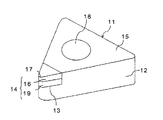
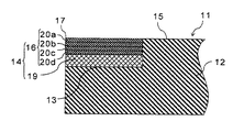
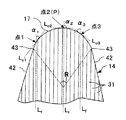
図1は本発明の切削工具を示す概略斜視図であり、図2は、図1の切削工具の部分断面図である。
【0016】
図1に示す切削工具11は、平板状をなし、工具本体12の角部に形成された取付座13には、裏板19と複合構造体16とが一体化された切刃チップ14がろう付けされている。
【0017】
また、この切削工具11によれば、すくい面15と横逃げ面21との交差稜線部に切刃稜17が構成されている。
【0018】
さらに、切削工具11の中央部には、バイトなどの工具に取り付けるためのクランプねじ等が挿通される取付孔18が形成されている。
【0019】
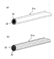
図3(a)(b)は、本発明において用いられている複合繊維体の概略斜視図である。(a)の複合繊維体31sは、芯材32とこの芯材32の外周を被覆し芯材32とは異なる組成の材料からなる被覆層33とからなるシングルタイプの繊維体である。また、(b)の複合繊維体31mは、(a)のシングルタイプの繊維体の集合体を伸延したものでマルチタイプの繊維体である。本発明によれば、切刃稜17を形成する前記複合構造体16は、このような(a)または(b)の複合繊維体31を集束した構造体によって形成されている。望ましくは、(b)のマルチタイプの繊維体を用いることが耐欠損性に優れる。
【0020】
本発明の切削工具によれば、幅方向に並列に整列した複数の複合繊維体31の繊維方向、あるいは複合繊維体31を構成する芯材32と被覆層33との界面方向が、切刃稜17の稜線と平行にならないように配置することが重要である。
【0021】
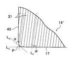
即ち、図5の切刃チップの平面図に示すように、複合繊維体31、31、・・・の繊維方向Lfと、切刃稜17における稜線での接線LCとのなす角度αが、切刃部分のどの場所においても2°以上、好ましくは5°以上、より好ましくは10°以上であることが重要である。つまり、切刃稜17における点1での角度α1、点2での角度α2、点3での角度α3が、いずれも上記範囲を満足することが重要である。
【0022】
特に、切刃稜17のうち、切刃稜17のノーズR部の頂点Pとなる点2における接線Lc2とのなす角度α2は45°以上、特に70°以上、より望ましくは85°以上であることがよい。
【0023】
これによって、切削時にかかる最も高い応力の方向が配列された複合繊維体31の境界方向、または複合繊維体31の芯材32と被覆層33との界面方向からずれることによって、この界面に切削による応力が集中するのを防止し、且つ発生した応力を高強度で高靭性である複合繊維体31の長手方向に応力を分散させることができる結果、切削工具における切刃稜17全体における耐欠損性を高めることができる。
【0024】
従って、前記角度αが上記範囲よりも小さいと、切削時にかかる応力にて複合繊維体31における芯材32と被覆層33との境界で剥離が発生するように引張応力がかかるために、切削時に切刃稜17に位置するこの境界部にて剥離してチッピングや欠損を生じやすくなる恐れがある。
【0025】
ここで、上記角度αは、工具形状に対する複合繊維体31における複合繊維体31の配置方向、および切刃稜17の形成領域、すなわちノーズR部の形状や角度R等の工具形状そのものを調整することによって制御される。例えばノーズR部の角度Rが90°未満、特に80°以下、さらに60°以下ですくい面15が菱形形状からなる、いわゆるT、D、Vタイプ形状のスローアウェイチップが適応可能である。なお、図5によれば、ノーズR部は、頂点(P)から両方向に拡がり、直線部42との境であるつなぎ部43までの稜線を意味する。
【0026】
なお、図5によれば、複合繊維体31の繊維方向LfとノーズR部の頂点Pにおける接線Lc2とのなす角度αが90°、すなわち、複合繊維体31の繊維方向LfがノーズR部の頂点Pに向かって垂直に伸びるように整列した配列となっている。
【0027】
また、このノーズRの角度Rが90°ですくい面15の形状が正方形形状からなる、いわゆるSタイプ形状のスローアウェイチップにおいては、図6のようにノーズR部の片側のみを切刃稜17として用い、逆側45は切刃として使用しない、すなわち右勝手または左勝手に限定されたスローアウェイチップであれば、複合繊維体31の繊維方向Lfと各切刃位置での接線LC1とのそれぞれの角度αが2°以上を満足する限り、複合繊維体31の繊維方向LfとノーズR部の頂点Pにおける接線Lc2とのなす角度αが45°以下となっても差し支えない。
【0028】
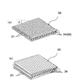
さらに、本発明によれば、図2および図4に示すように、複合構造体16が、複数の複合繊維体31を一方向に並べ整列させた複合層20a〜20dを厚み方向に複数層積層した構造体によって形成してなるものであるが、本発明によれば、図4に示すように、複合構造体を作製するにあたって、複合シート34の向きが隣接する複合層間で複合繊維体31の向きが異なるように積層したものであることが大きな特徴であり、これによって複合構造体16の靭性をさらに高めて、切削工具としての耐欠損性をさらに向上させることができる。
【0029】
この隣接する複合層間で複合繊維体31の向きの相違を示す角度βは、5〜90°の範囲、特に25〜60°であることが望ましい。なお図4(a)は、βを45°で積層したもの、図4(b)はβを90°で積層したものである。
【0030】
なお、本発明によれば、切削工具としてはソリッドタイプの工具であっても良いが、低コスト、製造の容易さ等の点でスローアウェイ式の工具であることが望ましい。さらに、図1、2のように、工具本体12の切刃部分を切り欠いて複合繊維体31からなる複合構造体16を有する切刃チップ14を取付座13にはめ込んでろう付け等で固定することによって、工具の切刃形状に対する複合繊維体31の繊維方向を容易に制御することができ、また、複数のコーナーに切刃を設ける際にも複合繊維体31の配列が容易に行えるというメリットがある。
【0031】
本発明において用いる複合繊維体31の芯材32を構成する材質としては、ダイヤモンド60〜99質量%を、鉄族金属、炭酸塩、硫酸塩および水酸化物から選ばれる少なくとも一種、特にコバルトおよび/またはニッケルからなる結合金属1〜40質量%にて結合してなるダイヤモンド焼結体が好適に使用可能である。なお、ダイヤモンド焼結体中には適宜周期律表4a、5aおよび6a族金属の炭化物、窒化物および炭窒化物の1種以上からなる硬質粒子を含有せしめることも可能である。
【0032】
また、芯材32を構成する他の材質としては、立方晶窒化硼素(以下cBNとする)20〜99質量%を、周期律表4a、5a、6a族金属およびシリコン、アルミニウムの炭化物、窒化物、炭窒化物、硼素化物および酸化物と、鉄族金属の1種以上からなる結合材1〜80質量%にて結合してなるcBN焼結体が好適に使用可能である。
【0033】
さらに、芯材32を構成する材質としては、周期律表4a、5aおよび6a族金属の炭化物、窒化物および炭窒化物の1種以上からなる第1の硬質粒子、特に炭化タングステン、炭化チタン、炭窒化チタン、窒化チタン、炭化タンタル、炭化ニオブ、炭化ジルコニウム、窒化ジルコニウム、炭化バナジウム、炭化クロムおよび炭化モリブデンの群から選ばれる少なくとも1種、さらには炭化タングステン、炭化チタンまたは炭窒化チタンの群から選ばれる少なくとも1種65〜98質量%を、鉄、コバルトおよびニッケルの群から選ばれる少なくとも1種、特にコバルトおよび/またはニッケルからなる結合金属2〜35質量%にて結合してなる第1の硬質焼結体、特に超硬合金またはサーメットが好適に使用可能である。
【0034】
また、芯材32を構成するさらに他の材質として、上記硬質焼結体以外にも、周期律表4a、5aおよび6a族金属、アルミニウム、シリコンの群から選ばれる少なくとも1種の酸化物、炭化物、窒化物および炭窒化物からなる第1のセラミックス、中でもアルミナ−炭化チタン(炭窒化チタン)、炭化珪素、窒化珪素、ジルコニア、硼化チタンの群から選ばれる少なくとも1種、さらにはアルミナ−炭化チタン(炭窒化チタン)および/または炭化珪素が好適に使用可能である。なお、第1のセラミックス中には適宜焼結助剤成分を含有せしめることも可能である。
【0035】
一方、芯材32の外周を覆う被覆層33の材質としては、芯材32とは異なる材質の硬質焼結体またはセラミックスを用いる。また、鉄、コバルトおよびニッケルなどの金属も単独で使用可能である。
【0036】
さらに、芯材32−被覆層33との組み合わせは、例えば超硬合金−サーメット、超硬合金−cBN焼結体、超硬合金−ダイヤモンド焼結体、超硬合金−アルミナ、超硬合金−窒化珪素、サーメット−超硬合金、サーメット−cBN焼結体、サーメット−ダイヤモンド焼結体、サーメット−アルミナ、サーメット−窒化珪素、(アルミナ,炭窒化チタン)−アルミナ、炭化珪素−窒化珪素、(炭化珪素、窒化珪素)−窒化珪素、炭化珪素−ダイヤモンド焼結体、cBN焼結体−サーメット、cBN焼結体−超硬合金、およびダイヤモンド焼結体−超硬合金の群から選ばれる1種が特に好適に使用可能である。
【0037】
とりわけ、工具としての耐欠損性を向上させるためには、複合繊維体31間の界面における密着性を結合相の相互拡散や反応などによって高めた芯材32および被覆層33、例えば、芯材32−被覆層33として、サーメット−超硬合金、超硬合金−サーメット、ダイヤモンド焼結体−超硬合金、超硬合金−ダイヤモンド焼結体、ダイヤモンド焼結体−サーメット、サーメット−ダイヤモンド焼結体、cBN焼結体−超硬合金、超硬合金−cBN焼結体、サーメット−cBN焼結体、cBN焼結体−サーメット等の組織中にコバルトおよび/またはニッケルの鉄族金属を含有する材質を選定するのが望ましい。
【0038】
一方、芯材32をなす焼結体の結晶粒子の平均粒径は、複合繊維体31の硬度および強度向上の点、および芯材32と被覆層33中の結合材(結合金属、焼結助剤)の含有量を適正化する点で0.05〜10μm、特に0.1〜3μmであることが望ましく、他方、被覆層33をなす結晶粒子の平均粒径は、複合繊維体31の靭性向上の点で、0.01〜5μm、特に0.01〜2μmであることが望ましい。
【0039】
また、複合繊維体31のサイズは、工具としての耐欠損性を高めるために、芯材32の直径が5〜300μm、被覆層33を含めた複合繊維体31の1本の直径が6〜500μmであることが望ましい。
【0040】
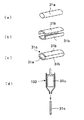
次に、本発明の切削工具の製造方法について説明する。まず、本発明において用いられる複合繊維体の製造方法について説明する。図7、図8は、図3の複合繊維体31の製造方法を説明するための工程図である。
【0041】
複合繊維体を作製するにあたり、まず、芯材用成形体を作製する。芯材用成形体を作製する方法は基本的には公知の粉末冶金法、つまり原料粉末と結合剤(バインダ)とを混合して成形する方法によって作製することができる。
【0042】
具体的な方法として、上述した芯材のうち超硬合金を選択した場合について説明すると、初めに、平均粒径0.01〜10μmの炭化タングステン粉末を0〜80質量%、特に20〜70質量%と、平均粒径0.01〜10μmの鉄族金属粉末を5〜20質量%と、の割合で混合し、さらに有機バインダ、可塑剤、溶剤を添加して混錬し、プレス成形または鋳込み成形等の成形法により円柱形状に成形して芯材用成形体31aを作製する(図7(a)参照)。
【0043】
ここで、後述する共押出成形によって均質な複合成形体を得るためには、前記有機バインダの添加量を30〜70体積%、特に40〜60体積%とすることが望ましい。
【0044】
有機バインダとしては、パラフィンワックス、ポリスチレン、ポリエチレン、エチレン‐エチルアクリレート、エチレン‐ビニルアセテート、ポリブチルメタクリレート、ポリエチレングリコール、ジブチルフタレート等を使用することができる。
【0045】
一方、芯材用成形体31aとは異なる組成の被覆層をなす材料を前述したバインダとともに混錬してプレス成形、押出成形または鋳込み成形等の成形方法により半割円筒形状の2本の被覆層用成形体31bを作製し、この被覆層用成形体31bを芯材用成形体31aの外周を覆うように配置した成形体31cを作製する(図7(b)および(c)参照)。
【0046】
そして、押出機100を用いて芯材用成形体31aと被覆層用成形体31bとからなる上記成形体31cを共押出成形することにより、芯材用成形体31aの周囲に被覆層用成形体31bが被覆され、細い径に伸延された図3(a)のシングルタイプの複合繊維体31sを作製することができる(図7(d)参照)。
【0047】
また、複合繊維体31の形成にあたり、図8(a)に示すように、上記共押出した長尺状の複合繊維体31sを複数本集束した集束体36を再度共押出成形することによって、図3(b)の繊維密度の高いマルチタイプの複合繊維体31mを作製することができる。なお、複合繊維体31s、31mの断面は、円形のみならず、四角形、三角形でもよい。
【0048】
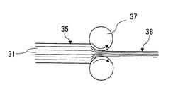
そして、図4(a)(b)に示したように、この長尺状の複合繊維体31を2列〜100列に整列させて型内で加熱加圧して複合シート34を得、さらにこの複合シート34の複数枚を、隣接する複合シート34の複合繊維体31同士の向きがβの角度で異なるように前記シートを厚み方向に複数枚積層して積層体35を得る。但し、この場合、複合シートのうち切刃を形成する最上層の複合シート34における複合繊維体31の繊維方向が前述したように切刃稜線との関係で特定の角度になるように調整することが必要である。また、角度βは、各複合シート層で必ずしも同じである必要はなく、角度βが層間毎に異なっていてもよい。
【0049】
また、この積層体35を必要に応じ、図9に示すように、一対のローラ37間に通して圧延処理し、さらに高密度の複合積層体38を作製することもできる。
【0050】
そして、前記積層体35または複合積層体38を300〜700℃で10〜200時間で昇温または保持させて脱バインダ処理し、ついで真空中、または不活性雰囲気中、所定温度、時間で焼成して一体化することにより複合構造体16を作製することができる。
【0051】
この複合構造体16は、切削工具11の切刃稜17との関係が前述したように所定の角度αとなるように、ワイヤー放電加工機、切削、研磨等で切刃形状に加工する。
【0052】
次に、上記のようにして作製した複合構造体16の下面に、超硬合金等の硬質焼結体で形成された裏板19を取り付け切刃チップ14を作製する。この裏板19は、通常、上記した積層体の焼成時に同時に焼成して複合構造体16と一体化することが望ましい。
【0053】
そして、裏板19と複合構造体16とが一体化された切刃チップ14を、取付座13に銀ろうなどを用いてろう付けする。なお、複合構造体16に裏板19を取り付けず、複合構造体16を工具本体12に直接ろう付けすることも可能である。
【0054】
【実施例】
以下、実施例を挙げて本発明を詳細に説明するが、本発明は以下の実施例のみに限定されるものではない。
【0055】
実施例
平均粒径1.5μmのダイヤモンド粉末に、有機バインダとしてセルロース、ポリエチレングリコールを、溶剤としてポリビニルアルコールを総量で100体積部加えて混錬して、直径が20mmの円柱形状にプレス成形して芯材用成形体を作製した。
【0056】
一方、平均粒径2.0μmのWC粉末89重量%と、平均粒径1.0μmのCo粉末11質量%とを混合し、これに、上記と同様の有機バインダ、溶剤を加えて混錬し、半割円筒形状の厚さが1mmの被覆層用成形体をプレス成形にて2つ作製し、これらを前記芯材用成形体の外周を覆うように配置して複合繊維体を作製した。
【0057】
そして、上記複合繊維体を共押出して直径が2mmの伸延された複合成形体を作製した後、この伸延された複合成形体100本を集束して再度共押出成形し、直径が1mmのマルチフィラメント構造の複合繊維体を作製した。
【0058】
次に、上記マルチフィラメント構造の複合繊維体を100mmの長さにカットし、並列に整列させてシート状とし、この複合シート3枚を隣接する複合シート間の複合繊維体の向き(角度β°)が表1となるように積層して積層体を作製した。
【0059】
その後、この積層体の下面に厚さ5mmの超硬合金の焼結体からなる裏板を配し、これを300〜700℃まで100時間で昇温することによって脱バインダ処理を行った後、超高圧装置に配置し、1450℃×15分の条件で焼成し、複合構造体と裏板が一体化された切刃チップを作製した。その後、この切刃チップを加工して、超硬合金からなる工具本体の取付座に、銀ろうを用いて700℃でろう付けした。
【0060】
ここで、表1にこの切削工具において、前記シートを構成する複合繊維体の繊維方向Lfと切刃チップの切刃稜線における接線Lcとのなすそれぞれの角度αのうち最も小さい角度をαminとし、チップ先端角度(ノーズR)を表1に示した。なお、表1中、試料No.15、16、17についてはノーズR部において切刃として用いる部分はノーズR頂点Pから右半分のみ、すなわち右勝手の刃先仕様とした。また、ノーズR頂点Pにおける繊維方向Lfと頂点Pにおける接線Lcとのなす角度αpを表1に示した。
【0061】
比較例
実施例と同様の組成および構造のマルチフィラメントのシートを用いて複合繊維体の繊維方向LfとノーズR頂点の接線Lcとが平行となる形状に切刃チップを作製し、複合繊維体の繊維方向LfとノーズR頂点の接線Lc2とが平行となるように配置してろう付けする以外は実施例1と同様の方法にて切削工具を作製した。
【0062】
上記のようにして作製した各切削工具を用いて、
切込み量d=1mm、
切削速度V=100m/分、
送りf=0.1mm/rev
にて複数の被削材(ADC12、4本溝入り)を切削し、欠損またはチッピングが発生するまでの被削材の加工数(最大2000個)を評価した。
【0063】
【表1】

【0064】
【発明の効果】
以上、詳述したとおり、本発明によれば、複合繊維体の繊維方向と切刃のなす角度や複合構造体における各複合層間の角度を制御することによって、複合繊維体の界面における剥離が抑制され、且つ切刃で発生する応力を複合繊維体によって効果的に拡散し緩和させることができるために、切刃における欠損を抑制することができ、高い耐欠損性を有する切削工具を得ることができる。
【図面の簡単な説明】
【図1】本発明にかかる切削工具の一実施形態を示す斜視図である。
【図2】図1の切削工具の切刃チップ付近の断面図である。
【図3】複合繊維体の構造を示す斜視図である。
【図4】複合構造体の構造を説明するための概略斜視図である。
【図5】図1の切刃チップのすくい面側から見た平面図である。
【図6】本発明の他の実施態様について、すくい面側から見た模式図である。
【図7】シングルタイプの複合繊維体の製造方法を示す工程図である。
【図8】マルチタイプの複合繊維体の製造方法を示す工程図である。
【図9】複合積層体の製造方法の一例を説明するための図である。
【符号の説明】
11 切削工具
12 工具本体
13 取付座
14 切刃チップ
15 すくい面
16 複合構造体
17 切刃稜
19 裏板
31 複合繊維体
32 芯材
33 被覆層
42 直線部
43 つなぎ部[0001]
TECHNICAL FIELD OF THE INVENTION
The present invention particularly relates to a cutting tool having improved fracture resistance and wear resistance.
[0002]
[Prior art]
The cutting edge of a throw-away tip used as a cutting tool for processing various materials such as steel is generally formed of a cemented carbide or the like. Although this cutting tool is widely used from precision cutting to general-purpose cutting, the above-mentioned conventional cutting tool does not have sufficient toughness, and it is necessary to further increase the chipping resistance of the cutting edge.
[0003]
Further, according to Patent Document 1 below, a highly tough composite fiber body in which a coating layer made of WC or the like is arranged on the outer periphery of a core material in the form of a composite fiber body made of diamond or the like is disclosed. It has been proposed to improve the fracture resistance of a drilling tool by attaching a composite fiber to the entire circumference.
[0004]
[Patent Document 1]
US Patent No. 6,063,502
[Problems to be solved by the invention]
However, Patent Document 1 describes a specific example for an excavating tool, but does not describe a cutting tool such as turning or milling, and applies a composite fiber body to such a cutting tool. No specific structure has been studied at all in order to sufficiently exhibit the properties of the fibrous body at that time.
[0006]
Therefore, an object of the present invention is to sufficiently apply the properties of a composite fiber body to a cutting tool when the composite fiber body composed of a core material and a coating layer in the form of a composite fiber body having high toughness is applied to the cutting tool. Another object of the present invention is to provide a cutting tool having high fracture resistance.
[0007]
[Means for Solving the Problems]
The present inventor converges such a composite fiber to form a composite structure, and when forming a cutting edge of a cutting tool with the composite structure, cutting characteristics largely depend on the orientation of the fiber and the angle between the cutting edge. It has been found that by controlling the angle within a predetermined range, it is possible to form a cutting tool having excellent fracture resistance by taking advantage of the characteristics of the composite fiber body, and reached the present invention.
[0008]
That is, in the cutting tool of the present invention, at least the corner portion including the cutting edge ridge is arranged in parallel with a composite fiber body comprising a core material and a coating layer having a composition different from that of the core material and covering the outer periphery of the core material. A composite structure in which a plurality of composite layers formed in the thickness direction are laminated and bundled, and the direction of the composite fiber body is different between the adjacent composite layers in the composite structure, and the fiber direction at the cutting edge ridge is cut. The angle α between the tangent of the blade ridge and the tangent is 2 ° or more.
[0009]
In particular, it is desirable that the angle α formed by the tangent at the vertex of the corner of the cutting tool is 45 ° or more.
[0010]
According to the cutting tool of the present invention, the angle α between the fiber direction of the composite fiber body constituting the cutting edge ridge portion and the tangent to the cutting edge ridge line is 2 ° or more, particularly the fiber direction of the composite fiber body. And the tangent of the apex of the nose R portion are arranged so that the angle α is 45 ° or more. Due to the structure of the composite fibrous body, the entire composite structure has high hardness, high strength, and high toughness. Excellent characteristics are sufficiently exhibited, and high fracture resistance of the cutting blade can be realized.
[0011]
This is because the direction of the stress applied during cutting deviates from the direction of the interface between the composite fiber bodies in the composite structure or the direction of the interface between the core material and the coating layer in each composite fiber body, so that the stress is concentrated on the interface. In addition, the high-strength, high-toughness composite fibrous body itself can receive stress in the longitudinal direction and disperse the stress, and as a result, defects in the cutting edge can be effectively suppressed.
[0012]
Further, according to the present invention, the composite structure has a configuration in which a plurality of composite layers in which the composite fibrous bodies are arranged in parallel in one direction are stacked and bundled in the thickness direction, and the composite fibrous body is formed between adjacent composite layers. By configuring so that the directions are different, the toughness of the composite structure can be further improved, and as a result, defects in the cutting edge can be more effectively suppressed.
[0013]
Further, the cutting tool is separated into a tool body and a cutting edge chip brazed to a mounting seat of the tool body, and the cutting edge chip is formed by a composite structure in which the composite fibrous body is bundled. The fiber direction of the composite fiber body with respect to the cutting edge shape can be easily controlled, and the arrangement of the composite fiber bodies when the cutting blades are provided at a plurality of corners can be easily performed.
[0014]
BEST MODE FOR CARRYING OUT THE INVENTION
Hereinafter, an embodiment of the present invention will be described in detail.
[0015]
FIG. 1 is a schematic perspective view showing the cutting tool of the present invention, and FIG. 2 is a partial sectional view of the cutting tool of FIG.
[0016]
A
[0017]
According to the
[0018]
Further, in the center of the
[0019]
FIGS. 3A and 3B are schematic perspective views of a composite fiber used in the present invention. The composite
[0020]
According to the cutting tool of the present invention, the fiber direction of the plurality of composite
[0021]
That is, as shown in the plan view of cutting insert of Figure 5, the
[0022]
In particular, among the cutting edges 17, cutting edge angle alpha 2 between the tangent line Lc2 at 2 point where the apex P of the nose R of the
[0023]
As a result, the direction of the highest stress applied during cutting deviates from the boundary direction of the composite
[0024]
Therefore, if the angle α is smaller than the above range, tensile stress is applied so that the stress applied at the time of cutting causes separation at the boundary between the
[0025]
Here, the angle α adjusts the arrangement direction of the composite
[0026]
Note that according to FIG. 5, the angle α is 90 ° and tangent L c2 at vertex P of fiber direction L f and nose R of the
[0027]
In a so-called S-type indexable insert in which the angle R of the nose R is 90 ° and the shape of the
[0028]
Further, according to the present invention, as shown in FIGS. 2 and 4, the
[0029]
The angle β indicating the difference in the orientation of the
[0030]
According to the present invention, the cutting tool may be a solid type tool, but is preferably a throw-away type tool in terms of low cost, ease of manufacture, and the like. Further, as shown in FIGS. 1 and 2, the cutting edge portion of the
[0031]
As a material constituting the
[0032]
Other materials constituting the
[0033]
Further, as a material constituting the
[0034]
In addition to the hard sintered body, at least one oxide or carbide selected from the group consisting of metals of the 4a, 5a, and 6a groups of the periodic table, aluminum, and silicon may be used as the other material constituting the
[0035]
On the other hand, as a material of the
[0036]
Further, the combination with the
[0037]
In particular, in order to improve the fracture resistance as a tool, the
[0038]
On the other hand, the average particle size of the crystal grains of the sintered body forming the
[0039]
The size of the composite
[0040]
Next, a method for manufacturing the cutting tool of the present invention will be described. First, a method for producing a composite fiber used in the present invention will be described. 7 and 8 are process diagrams for explaining a method for manufacturing the
[0041]
In producing a composite fiber body, first, a molded body for a core material is produced. The method of producing the core material molded body can be basically produced by a known powder metallurgy method, that is, a method of molding by mixing a raw material powder and a binder (binder).
[0042]
As a specific method, a case where a cemented carbide is selected from the above-described core materials will be described. First, tungsten carbide powder having an average particle size of 0.01 to 10 μm is added in an amount of 0 to 80% by mass, particularly 20 to 70% by mass. % And an iron group metal powder having an average particle size of 0.01 to 10 μm in a ratio of 5 to 20% by mass, and further kneading by adding an organic binder, a plasticizer and a solvent, and press molding or casting. It is molded into a cylindrical shape by a molding method such as molding to produce a core material molded
[0043]
Here, in order to obtain a homogeneous composite molded article by co-extrusion molding described later, the amount of the organic binder to be added is preferably 30 to 70% by volume, particularly preferably 40 to 60% by volume.
[0044]
As the organic binder, paraffin wax, polystyrene, polyethylene, ethylene-ethyl acrylate, ethylene-vinyl acetate, polybutyl methacrylate, polyethylene glycol, dibutyl phthalate and the like can be used.
[0045]
On the other hand, a material forming a coating layer having a composition different from that of the core
[0046]
The
[0047]
In forming the composite
[0048]
Then, as shown in FIGS. 4 (a) and 4 (b), the long
[0049]
Further, if necessary, the laminate 35 may be passed through a pair of
[0050]
Then, the laminate 35 or the
[0051]
The
[0052]
Next, a
[0053]
Then, the
[0054]
【Example】
Hereinafter, the present invention will be described in detail with reference to examples, but the present invention is not limited to the following examples.
[0055]
Example: To a diamond powder having an average particle size of 1.5 μm, cellulose and polyethylene glycol as organic binders and 100 parts by volume of polyvinyl alcohol as a solvent were added and kneaded, and the mixture was press-formed into a cylindrical shape having a diameter of 20 mm. A molded body for a core material was produced.
[0056]
On the other hand, 89% by weight of WC powder having an average particle size of 2.0 μm and 11% by mass of Co powder having an average particle size of 1.0 μm were mixed, and the same organic binder and solvent as described above were added thereto and kneaded. Two molded articles for a coating layer having a half-cylindrical shape and a thickness of 1 mm were produced by press molding, and these were arranged so as to cover the outer periphery of the molded article for a core material, to produce a composite fiber body.
[0057]
Then, the composite fiber body is co-extruded to produce an elongated composite molded article having a diameter of 2 mm. Then, 100 elongated composite molded articles are bundled and co-extruded again to obtain a multifilament having a diameter of 1 mm. A composite fiber body having a structure was produced.
[0058]
Next, the composite fibrous body having the multifilament structure is cut into a length of 100 mm, aligned in parallel to form a sheet, and the three composite sheets are oriented in the direction (angle β °) of the composite fibrous body between adjacent composite sheets. ) Were laminated as shown in Table 1 to produce a laminate.
[0059]
After that, a back plate made of a sintered body of a 5 mm thick cemented carbide is arranged on the lower surface of the laminate, and the temperature is raised to 300 to 700 ° C. in 100 hours to perform a binder removal process. It was placed in an ultra-high pressure device and baked under the conditions of 1450 ° C. × 15 minutes to produce a cutting edge chip in which the composite structure and the back plate were integrated. Thereafter, this cutting edge chip was processed and brazed at 700 ° C. to a mounting seat of a tool body made of a cemented carbide using a silver braze.
[0060]
Here, .alpha.min in the cutting tool shown in Table 1, the smallest angle of the respective angle α formed by the tangent line L c of the cutting edge ridge line of the fiber direction L f and cutting insert of the composite fiber constituting the sheet Table 1 shows the tip end angle (nose radius). In Table 1, the sample No. With respect to 15, 16, and 17, the portion used as the cutting edge in the nose R portion was only the right half from the nose R vertex P, that is, the right-handed cutting edge specification. Further, the angle αp between the tangent line L c in the fiber direction L f and the vertex P of the nose R vertex P shown in Table 1.
[0061]
The tangent L c of the fiber direction L f and nose R vertices of composite fiber material with a sheet of multifilament having the same composition and structure as the comparative example embodiment to produce a cutting edge tip to a shape to be parallel, composite fibers except that the body and the tangent line L c2 fiber direction L f and nose R vertex of brazed disposed in parallel was produced cutting tools in the same manner as in example 1.
[0062]
Using each cutting tool produced as described above,
Cutting depth d = 1mm,
Cutting speed V = 100m / min,
Feed f = 0.1mm / rev
A plurality of workpieces (ADC12, with four grooves) were cut by using, and the number of workpieces processed (up to 2000 pieces) until chipping or chipping occurred was evaluated.
[0063]
[Table 1]
[0064]
【The invention's effect】
As described above in detail, according to the present invention, by controlling the angle between the fiber direction and the cutting edge of the composite fiber body and the angle between the respective composite layers in the composite structure, separation at the interface of the composite fiber body is suppressed. In addition, since the stress generated at the cutting edge can be effectively diffused and relaxed by the composite fiber body, it is possible to suppress the chipping at the cutting edge and obtain a cutting tool having high chipping resistance. it can.
[Brief description of the drawings]
FIG. 1 is a perspective view showing an embodiment of a cutting tool according to the present invention.
FIG. 2 is a sectional view of the vicinity of a cutting edge tip of the cutting tool of FIG. 1;
FIG. 3 is a perspective view showing a structure of a composite fiber body.
FIG. 4 is a schematic perspective view for explaining the structure of the composite structure.
FIG. 5 is a plan view of the cutting edge tip of FIG. 1 as viewed from the rake face side.
FIG. 6 is a schematic view of another embodiment of the present invention as viewed from the rake face side.
FIG. 7 is a process chart showing a method for producing a single type composite fiber body.
FIG. 8 is a process chart showing a method for producing a multi-type composite fiber body.
FIG. 9 is a diagram illustrating an example of a method for manufacturing a composite laminate.
[Explanation of symbols]
REFERENCE SIGNS
Claims (3)
芯材と、該芯材の外周を被覆し芯材とは異なる組成の被覆層とからなる複合繊維体を平行に整列した複合層を厚み方向に複数層積層して集束した複合構造体からなり、該複合構造体において隣接する前記複合層間で前記複合繊維体の向きが異なり、且つ前記切刃稜における繊維方向と切刃稜線の接線とのなす角度αが2°以上であることを特徴とする切削工具。At least the corners including the cutting edge,
A composite structure is formed by laminating a plurality of composite layers in which a composite fiber body composed of a core material and a coating layer having a composition different from that of the core material and covering the outer periphery of the core material is laminated in the thickness direction and bundled. The direction of the composite fiber body is different between the adjacent composite layers in the composite structure, and the angle α between the fiber direction at the cutting edge and the tangent to the cutting edge is 2 ° or more. Cutting tools.
Priority Applications (1)
| Application Number | Priority Date | Filing Date | Title |
|---|---|---|---|
| JP2003043166A JP2004249404A (en) | 2003-02-20 | 2003-02-20 | Cutting tool |
Applications Claiming Priority (1)
| Application Number | Priority Date | Filing Date | Title |
|---|---|---|---|
| JP2003043166A JP2004249404A (en) | 2003-02-20 | 2003-02-20 | Cutting tool |
Publications (1)
| Publication Number | Publication Date |
|---|---|
| JP2004249404A true JP2004249404A (en) | 2004-09-09 |
Family
ID=33026244
Family Applications (1)
| Application Number | Title | Priority Date | Filing Date |
|---|---|---|---|
| JP2003043166A Pending JP2004249404A (en) | 2003-02-20 | 2003-02-20 | Cutting tool |
Country Status (1)
| Country | Link |
|---|---|
| JP (1) | JP2004249404A (en) |
Cited By (2)
| Publication number | Priority date | Publication date | Assignee | Title |
|---|---|---|---|---|
| CN105922295A (en) * | 2016-06-01 | 2016-09-07 | 山东大学 | High-strength abrasion-resistant tool with vertical alignment of primary strengthening phase fibers |
| JP2020520412A (en) * | 2017-05-05 | 2020-07-09 | ハイペリオン マテリアルズ アンド テクノロジーズ (スウェーデン) アクティエボラーグ | Articles including cermet parts, and methods for making the articles |
-
2003
- 2003-02-20 JP JP2003043166A patent/JP2004249404A/en active Pending
Cited By (3)
| Publication number | Priority date | Publication date | Assignee | Title |
|---|---|---|---|---|
| CN105922295A (en) * | 2016-06-01 | 2016-09-07 | 山东大学 | High-strength abrasion-resistant tool with vertical alignment of primary strengthening phase fibers |
| JP2020520412A (en) * | 2017-05-05 | 2020-07-09 | ハイペリオン マテリアルズ アンド テクノロジーズ (スウェーデン) アクティエボラーグ | Articles including cermet parts, and methods for making the articles |
| JP7299161B2 (en) | 2017-05-05 | 2023-06-27 | ハイペリオン マテリアルズ アンド テクノロジーズ (スウェーデン) アクティエボラーグ | Object containing cermet portion and method for manufacturing same |
Similar Documents
| Publication | Publication Date | Title |
|---|---|---|
| EP2582478B1 (en) | Cutter element of a ball nose end mill and method for making same | |
| EP3124147B1 (en) | Composite member and cutting tool | |
| JP4192037B2 (en) | Cutting tool and manufacturing method thereof | |
| JP4796316B2 (en) | Composite fiber body and cutting tool using the same | |
| JP2004249404A (en) | Cutting tool | |
| JP2004202597A (en) | Cutting tool | |
| WO2003082539A1 (en) | Honeycomb forming ferrule | |
| JP4220814B2 (en) | Cutting tool and manufacturing method thereof | |
| JP4061222B2 (en) | Cutting tools | |
| JP3954903B2 (en) | Cutting tools | |
| JP3954896B2 (en) | Cutting tool with breaker | |
| JP4960126B2 (en) | Brazing cBN tool | |
| JP4309777B2 (en) | Cutting tools | |
| JP4400850B2 (en) | Composite member and cutting tool using the same | |
| JP4484535B2 (en) | Diamond sintered body and cutting tool | |
| JP4889226B2 (en) | Composite sintered body and cutting tool | |
| JP4574129B2 (en) | Method for manufacturing composite structure | |
| JP5743868B2 (en) | Cutting tools | |
| JP4439240B2 (en) | Method for manufacturing composite structure | |
| JP4195797B2 (en) | Composite hard sintered body and cutting tool using the same | |
| JP2005014164A (en) | Cutting tool | |
| JP4198824B2 (en) | Cutting chip manufacturing method | |
| JP2004232001A (en) | Composite hard sintered compact, and composite member and cutting tool using it | |
| JP2004256851A (en) | Composite structure | |
| JP3828831B2 (en) | Composite hard sintered body and solid drill |
Legal Events
| Date | Code | Title | Description |
|---|---|---|---|
| A621 | Written request for application examination |
Free format text: JAPANESE INTERMEDIATE CODE: A621 Effective date: 20050810 |
|
| A977 | Report on retrieval |
Free format text: JAPANESE INTERMEDIATE CODE: A971007 Effective date: 20070420 |
|
| A131 | Notification of reasons for refusal |
Free format text: JAPANESE INTERMEDIATE CODE: A131 Effective date: 20070424 |
|
| A521 | Written amendment |
Free format text: JAPANESE INTERMEDIATE CODE: A523 Effective date: 20070614 |
|
| A02 | Decision of refusal |
Free format text: JAPANESE INTERMEDIATE CODE: A02 Effective date: 20070904 |