JP2004248896A - Vacuum cleaner - Google Patents
Vacuum cleaner Download PDFInfo
- Publication number
- JP2004248896A JP2004248896A JP2003042831A JP2003042831A JP2004248896A JP 2004248896 A JP2004248896 A JP 2004248896A JP 2003042831 A JP2003042831 A JP 2003042831A JP 2003042831 A JP2003042831 A JP 2003042831A JP 2004248896 A JP2004248896 A JP 2004248896A
- Authority
- JP
- Japan
- Prior art keywords
- dust
- dust collecting
- vacuum cleaner
- unit
- suction
- Prior art date
- Legal status (The legal status is an assumption and is not a legal conclusion. Google has not performed a legal analysis and makes no representation as to the accuracy of the status listed.)
- Pending
Links
Images


Abstract
Description
【0001】
【発明の属する技術分野】
本発明は、一般家庭で使用される電気掃除機に関するものである。
【0002】
【従来の技術】
従来のこの種の電気掃除機は図14に記載されているようなものが一般的であった。この電気掃除機を図14を用いて説明する。
【0003】
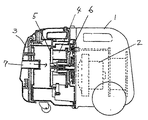
図14において、1は塵埃を吸引するための吸引風を発する電動送風機2を内蔵した掃除機本体であり、3は微細な塵埃捕集用のメインフィルター4とメインフィルター4に回転自在に取付けられた、粗い塵埃を捕集するためのプレフィルター5と、前記掃除機本体1間を密閉するパッキン6を内部に有し、前方に塵埃を取込む吸気口7を備えた集塵部であり、前記掃除機本体1と着脱自在に構成されている。
【0004】
そして、上記電気掃除機を運転すると、吸込具より吸引された塵埃が前記吸気口7を通って前記集塵部3内部に入る。すると、塵埃はまず前記プレフィルター5に吸着し粗い塵埃はここで捕集される。微細な塵埃は前記プレフィルター5を抜けてその奥にある前記メインフィルター4により捕集される。これらの過程を繰り返すことにより塵埃は前記集塵部3内部に蓄積される。
【0005】
集塵部3内部に蓄積された塵埃は、前記プレフィルター5及び前記メインフィルター4を、前記集塵部3より外すことにより外部に捨てることができる(例えば、特許文献1参照)。
【0006】
【特許文献1】
特開昭57−64027号公報
【0007】
【発明が解決しようとする課題】
しかしながら上記従来の構成では、掃除機本体1から、集塵部3を取り外し、塵埃を外部に捨てる際、吸気口7が集塵部3の前方にあるため、塵埃がこぼれ易いという問題があった。また、吸引された塵埃は前記吸気口7を通ってすぐに前記プレフィルター5に蓄積されるため、通気面積がすぐに減少し結果的に吸込み力の低下へと至るという問題点もあった。
【0008】
本発明は、上記課題を解決するもので、集塵部を掃除機本体から取り外したときの集塵部からの塵埃こぼれを防止するとともに、集塵性能を向上させた電気掃除機を提供することを目的とする。
【0009】
【課題を解決するための手段】
上記課題を課題を解決するために本発明は、吸引風を発する電動送風機と前記電動送風機の吸気口と連通する集塵部とを有する掃除機本体において、前記集塵部は前記掃除機本体と着脱自在に構成され、かつ前記集塵部の外郭の少なくとも上方が前記掃除機本体の外郭を形成するとともに、前記掃除機本体の外郭を形成する集塵部の外郭の略上方に吸引風が流入する吸気部を設けたもので、集塵部を掃除機本体から取り外し、塵埃を外部に捨てる際、吸気部が集塵部の略上方に設けられているため、塵埃は集塵部よりこぼれなくなり、また、吸気部を集塵部内に大きく突出させる必要がないため、集塵部内の集塵容積を増加させ集塵性能を向上させることができる。
【0010】
【発明の実施の形態】
本発明の請求項1記載の発明は、吸引風を発する電動送風機と前記電動送風機の吸気口と連通する集塵部とを有する掃除機本体において、前記集塵部は前記掃除機本体と着脱自在に構成され、かつ前記集塵部の外郭の少なくとも上方が前記掃除機本体の外郭を形成するとともに、前記掃除機本体の外郭を形成する集塵部の外郭の略上方に吸引風が流入する吸気部を設けたもので、集塵部を掃除機本体から取り外し、塵埃を外部に捨てる際、吸気部が集塵部の略上方に設けられているため、塵埃は集塵部よりこぼれなくなり、また、吸気部を集塵部内に大きく突出させる必要がないため、集塵部内の集塵容積を増加させ集塵性能を向上させることができる。
【0011】
本発明の請求項2記載の発明は、集塵部は塵埃を捕集する略円錐形状のフィルター部を有するとともに、前記集塵部に流入する塵埃を含む吸引風が、前記集塵部の内壁面に沿って旋回することで、前記塵埃と前記吸引風とを分離する遠心分離方式であるもので、上記方式では、集塵部内に捕集した塵埃を蓄積する構成のため、上記請求項1で述べた効果がより発揮できる。
【0012】
本発明の請求項3記載の発明は、集塵部は略円錐形状であるとともに、吸気部を前記集塵部の先端部近傍に設けたもので、吸引された塵埃は前記集塵部の内壁面に沿って回転するが、吸気部を集塵部の内壁面どうしの距離が小さい集塵部の先端部近傍に設けたため、旋回流が生じやすく、塵埃分離性能が向上する。
【0013】
本発明の請求項4記載の発明は、フィルター部に向かって吸引風が流入するように、吸気部を集塵部の長手方向の中心軸に対して斜め上方に設けたもので、吸引風は、電動送風機の吸引力により、集塵部の長手方向の中心軸に対して斜め上方から集塵部内に流入し、前記集塵部の内壁に沿い前記電動送風機の吸気口側に向かう旋回気流となる。このため、塵埃はこの回転気流に乗って前記集塵部内壁面を回転しながら前記電動送風機の吸気口側へ吸引される。この原理により、吸引された塵埃は前記集塵部の内壁面に沿って回転するため、その内側に位置する略円錐形状のフィルター部への塵埃の付着を抑えることができ、吸込み力の低下を抑制できる。また、塵埃は、吸気部より集塵部内壁面に沿って電動送風機の吸気側に向かい、前記電動送風機の吸引方向に蓄積されて、電動送風機の吸引力により塵埃の圧縮を行ない集塵量を増加させることができる。
【0014】
本発明の請求項5記載の発明は、吸引風下流側の吸気部の開口部を、集塵部の高さ方向の中心軸より高い位置に設けたもので、簡単な構成で、吸気部を大きくすることなく、塵埃廃棄時、吸気部から塵埃のもれを防止できる。
【0015】
本発明の請求項6記載の発明は、集塵部内に流入する吸引風が、フィルター部に向かって流れるように、開口部に案内部を設けたもので、吸気部から集塵部の内壁面に沿い電動送風機側に向かう旋回気流を増大させ、集塵部内部の略円錐形状部を有する塵埃捕集用のフィルター部への塵埃の付着をより抑え、吸込み力の低下を防止する。
【0016】
本発明の請求項7記載の発明は、フィルター部は、先端に開口を有し粗い塵埃を捕集するプレフィルターと細塵捕集用のメインフィルターとから構成されるとともに、前記プレフィルターの開口は、集塵部の壁面により閉塞されてなるもので、フィルター部をはずしただけで前記プレフィルターの開口より、メインフィルターに付着した塵埃を落とせるとともに、掃除機運転時には、プレフィルターの開口を通過して、塵埃がメインフィルターに付着することを部品点数を増やすことなく防止できるため、結果的にメインフィルターの塵埃詰まりを抑制し、集塵性能を向上させる。
【0017】
本発明の請求項8記載の発明は、プレフィルターの開口は、シール体を介して集塵部の壁面により閉塞されてなるもので、掃除機運転時には、プレフィルターの開口を通過して、塵埃がメインフィルターに付着することを確実に防止できるため、結果的にメインフィルターの塵埃詰まりを抑制し、集塵性能を向上させる。
【0018】
本発明の請求項9記載の発明は、塵埃が通過するホースと前記ホースを集塵部の吸気部に接続する略L字状の接続パイプとを備え、前記接続パイプは、前記吸気部に対して着脱かつ回動自在に構成されたもので、掃除機本体の構成は変わらず余計な部品を追加して掃除機本体の形状を複雑にしホース差込口を形成することなく、廉価構成で接続パイプとの接続が可能となり、直接ホースと集塵部が連通し、吸気部内での通路圧損がなくなり、性能低下を抑制する。また、ホースの一端と連通する接続パイプを回動させることより、ホース及び接続パイプを通る吸引風が左右等に偏って発生する。この原理により、前記接続パイプを回動させることより、集塵部の塵埃捕集用のプレフィルターには、さまざまな方向から吸引風が当たりプレフィルターの表面に蓄積された塵埃を吹飛ばし、プレフィルターへの塵埃の付着を抑えることができ、吸込み力の低下を抑制する。
【0019】
本発明の請求項10記載の発明は、吸引風を発する電動送風機と前記電動送風機の吸気口と連通する集塵部を有する掃除機本体において、前記集塵部と前記電動送風機との間で前記掃除機本体の下面外郭に本体持ち運び用の凹部を形成した電気掃除機で、掃除機本体の外形寸法を大きくせず、掃除機本体の無駄なスペースを活用し、本体持ち運び用の取っ手部を構成し使用性の向上が図れる。
【0020】
本発明の請求項11記載の発明は、凹部に対して隙間ノズル等の付属品が着脱自在であるもので、掃除機本体に隙間ノズル等の付属品を収納させる無駄なスペースを形成することなく、前記凹部を有効活用し、外観に違和感なく、前記隙間ノズル等の付属品を収納させることができる。
【0021】
本発明の請求項12記載の発明は、凹部に隙間ノズル等の付属品を係止させた時、前記隙間ノズル等の付属品の外郭が、掃除機本体の下面外郭の最下部と同一位置に位置するかまたはそれより内方に位置させる構成としたもので、前記隙間ノズル等が掃除機本体底部から突出せず、掃除機本体の走行中に前記隙間ノズル等が床面の凹凸に当たり傷付けたり、外れたりすることを抑制し、また、外観を損なわせることがなくなる。
【0022】
【実施例】
(実施例1)
以下、本発明の第1の実施例について、図1〜図8を用いて説明する。
【0023】
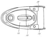
図1は掃除機本体の上面図であり、図2は掃除機本体の側面図であり、図3は掃除機本体の側断面図である。図4は集塵部の吸気部の部分拡大図であり、図5は吸気部の局部断面図である。図6は掃除機本体から集塵部を取り外した時の動作図で、図7はフィルター部の部分断面図である。図8は集塵部の側断面図である。
【0024】
図3において、掃除機本体10の後方には、塵埃を吸引するための吸引風を発する電動送風機11を内蔵し、前記電動送風機11の吸気口11aと連通し、吸引した塵埃を捕集する略円錐形状の集塵部12が設けられている。
【0025】
図6、図7において、集塵部12の後方上部に凹み部13が形成されており、この凹み部13の相対位置で、掃除機本体10に尾錠14が設けられており、前記尾錠14は、スプリング15によって、前後方向に摺動するように構成されている。掃除機本体10に構成された尾錠14を後方に移動することより、尾錠14の先端部が、集塵部12の凹み部13から外れ、集塵部12は掃除機本体10と着脱自在に構成されている。掃除機本体10の前方下面には移動用キャスター16が枢支されており、掃除機本体10の後方両側面には、一対の移動用車輪17が回転自在に備えられている。
【0026】
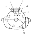
図8に示すように、集塵部12内には、微細な塵埃捕集用のメインフィルター18と、メインフィルター18に回転自在に取付けられた、粗い塵埃を捕集するための略円錐形状でメッシュ部19を有するプレフィルター20とからなるフィルター部21と、前記掃除機本体10間を密閉するパッキン32を有している。集塵部12の略上部前方には、集塵部12の円周空間の内壁面に沿う方向で、空気を前記集塵部12内に流入する開口部23を備えた吸気部24が備えられている。また、前記集塵部12の上方部の外郭は、掃除機本体10の外郭を形成するごとく露出している。なお、本実施例においては、前記集塵部12の上方部の外郭が、掃除機本体10の外郭を形成するごとく露出しているが、掃除機本体10に備え付けられれば他の部分が露出していてもかまわない。なお、前記吸気部24は、掃除機本体10の外郭を形成するごとく露出している部分に設けられている。
【0027】
上記構成において動作、作用を説明する。
【0028】
図6において、集塵部12を掃除機本体10から外し、塵埃を外部に捨てる際、塵埃は重力により下方に移動する。この時、吸気部24は、集塵部12の略上部前方にある為、塵埃は吸気部24からこぼれることなく使い勝手が向上する。
【0029】
また、図4、図5において略円錐形状の集塵部12の先端部近傍なる上部前方に、また、集塵部12の長手方向の中心軸に対して、上方へ40°〜70°の角度の範囲から、集塵部12内に吸引風が流入するように吸気部24を設けたため、電動送風機11を運転すると、塵埃は、集塵部12の電動送風機11の反吸気口11a側の内壁面に接する方向に設けられた吸気部24の吸気下流側先端の開口部23より、集塵部12内部へ捕集される。この際、吸気部24は、図5に示すように、集塵部12の内壁面の接線方向及び、電動送風機11の吸気口11a側へ開口している為、前記電動送風機11の吸引力により前記吸気部24より集塵部12の内壁面に沿い電動送風機11側に向かう旋回気流が集塵部12内部に発生する。このため、吸気部24から吸引された塵埃は、この回転気流に伴い集塵部12内壁面を回転しながらフィルター部21を通り、電動送風機11の吸引方向へと略水平方向に吸引される。この原理により吸引された塵埃は、図4、図5の矢印に示すように集塵部12の内壁面を回転しながら、電動送風機11側に移動するため、その内側に位置する略円錐形状部を有する塵埃捕集用のフィルター部21への塵埃の付着を抑えることができ、高吸込み力の維持を図る。また、塵埃は、集塵部12内部を回転しながら、電動送風機11側の吸引方向に蓄積されて、電動送風機11の吸引力により集塵部12の内壁面に押付けられた状態となり塵埃の圧縮が行われることより集塵量を増加させることができる。
【0030】
図5、図8において、吸気部24内部には、吸気部24の開口部23を開口させる弁体25が設けられている。弁体25には回動軸心26が形成されており、弁体25の回動軸心26は、吸気部24に形成した孔27に係止されて、弁体25は、図8に矢印Aに示すように回動自在に構成されている。このことにより電動送風機11停止時で、塵埃を外部に捨てる際、弁体25は重力方向に傾き、吸気部24の開口部23を覆うこととなり、集塵部12を傾けても塵埃が、吸気部24からもれる事を防止する。
【0031】
また、図3において、吸気部24から空気を流入する開口部23を集塵部12の中心より高い位置に形成することより、従来のように吸気部24を大きくすることなく簡単な構成で、塵埃廃棄時、吸気部24から塵埃のもれを防止できる。
【0032】
図5において、集塵部12内部で、吸気部24の開口部23より接線方向に案内部であるリブ体28が設けられている。このことより、吸気部24から集塵部12の内壁面に沿い電動送風機11側に向かう旋回気流がさらに増大し、集塵部12内部の略円錐形状部を有する塵埃捕集用のフィルター部21への塵埃の付着をより抑え、吸込み力の低下を防止する。
【0033】
図4、図8において、吸気部24から吸込まれた塵埃は、粗い塵埃は略円錐形状でメッシュ部19を有するプレフィルター20部で蓄積され、さらに細かい塵埃はプレフィルター20を連通し、細塵捕集用のメインフィルター18に捕集される構成となっている。塵埃を廃棄する際で、細塵捕集用のメインフィルター18に蓄積された塵埃は、プレフィルター20の先端部29に形成された開口30から排出される。電動送風機11の運転時には、開口30から塵埃が侵入していることを防止し集塵部12の前方より形成された凹リブ31により前記プレフィルター20の開口30を塞ぐ構成となっている。このことより、廉価な構成で部品点数を増やすことなく、プレフィルター20の開口30からの塵埃侵入を防ぎ、結果的にメインフィルター18の塵埃詰まりを抑制し、集塵性能を向上させる。また、プレフィルター20の開口30と、集塵部12より形成された凹リブ31との間に、エアータイト用のシール体であるパッキン体32を設けることより、確実に、プレフィルター20の開口30より通る塵埃が、メインフィルター18に行くことを防止し、集塵性能の低下を防止することができる。
【0034】
(実施例2)
以下、本発明の第2の実施例について、図9、図10を用いて説明する。
【0035】
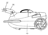
図9は掃除機本体の要部側面図である。図10は掃除機本体の要部断面図である。本実施例2は、実施例1から接続パイプまわりを詳細に表したものである。
なお、実施例1と同符号のものは同一構造を有し、その説明は省略する。
【0036】
図3、図9、図10において、集塵部12に連通し、塵埃を吸引するホース33の一端には、略L字状の接続パイプ34が設けられており、前記接続パイプ34には、左右一対の尾錠体35が形成されており、この尾錠体35はバネ体36によって摺動自在に構成されている。
【0037】
集塵部12に形成された吸気部24の上部には開口されたホース差込口37が形成されており、ホース差込口37内の外周リブ38に、接続パイプ34に形成された尾錠体35の先端凸部39が引っ掛り、吸気部24と接続パイプ34が着脱、及び、回動自在に設けられている。
【0038】
上記構成において動作、作用を説明する。
【0039】
図9において、ホース33と連通する接続パイプ34は、直接集塵部12内に連通し、吸気部24内を複雑にすることなく通路圧損を低減し、性能低下を抑制する。また、廉価な構成で接続パイプ34と吸気部24の接続が可能とすることができる。
【0040】
また、図9、10において、電動送風機11の動作時で、ホース33及び接続パイプ34を回動させたり、上下に振ったりすることにより、ホース33及び接続パイプ34を通る吸引風が左右等に偏った吸引風が発生する。この原理により、接続パイプ34を回動させることより、図9の矢印で示すように、さまざまな方向から吸引風が吹き込まれ、略円錐形状でメッシュ部19を有するプレフィルター20にもさまざまな方向から吸引風が当たり、プレフィルター20のメッシュ部19の表面に蓄積された塵埃を吹飛ばし、プレフィルター20への塵埃の付着を抑えることができ、結果的に吸込み力の低下を抑制する。
【0041】
(実施例3)
以下、本発明の第3の実施例について、図11〜図13を用いて説明する。
【0042】
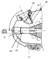
図11は掃除機本体を持ち上げた時の動作図である。図12は掃除機本体の要部断面側面図。図13は掃除機本体の底面図である。本実施例3は、実施例1からアタッチメントの収納に関して詳細に表したものである。なお、実施例1と同符号のものは同一構造を有し、その説明は省略する。
【0043】
図3、図11、図12において、電動送風機11に前方には、電動送風機室40と集塵部12との間を分割する格子形状を有した連通口41を形成した仕切壁42が形成されている。この仕切壁42の下方で、掃除機本体10底部に本体持ち運び用の略コ字状の凹部43が形成されている。
【0044】
上記構成において動作、作用を説明する。
【0045】
図11のように、従来無駄だったスペースを活用し、掃除機本体10の外形寸法を大きくすることなく、本体持ち運び用の略コ字状の凹部43にて掃除機本体10を、持運ぶことが可能となる。また、本体持ち運び用の略コ字状の凹部43は、重量物である電動送風機11の近傍にある為、掃除機本体10の振れに対して、手に加わる負担が軽減できる。
【0046】
図12、図13において、掃除機本体10底部で本体持ち運び用の略コ字状の凹部43に、隙間ノズル44等が挿入されている。この隙間ノズル44等は、略コ字状の凹部43の内部に形成された凸リブ45によって圧入で係止されており、隙間ノズル44等は着脱自在に構成されている。
【0047】
このことにより、掃除機本体10に前記隙間ノズル44等の付属品を収納させる無駄なスペースを形成することなく、略コ字状の凹部43を有効活用し、外観に違和感なく、隙間ノズル44等の付属品を収納させることができる。
【0048】
また、図12において、掃除機本体10底部で、略コ字状の凹部43に、隙間ノズル44等の付属品を係止している時、隙間ノズル44等の側外面46は、掃除機本体10底部の外面47と同一表面内に構成されている。このことより、隙間ノズル44等の付属品は、掃除機本体10底部から突出することなく、掃除機本体10の走行中でも隙間ノズル44等の付属品が、床面にある凹凸に当たって傷付けたり、外れたりすることを防止し、また、外観美を損なわせることがなくなる。
【0049】
【発明の効果】
以上説明したように本発明によれば、集塵部を掃除機本体から取り外したときの集塵部からの塵埃こぼれを防止するとともに、集塵性能を向上させた電気掃除機を提供できる。
【図面の簡単な説明】
【図1】本発明の第1の実施例における掃除機本体の平面図
【図2】同掃除機本体の側面図
【図3】同掃除機本体の側断面図
【図4】同掃除機本体の吸気部の部分拡大図
【図5】同掃除機本体の吸気部の局部断面図
【図6】同掃除機本体から集塵部を取り外した時の動作図
【図7】同掃除機本体のフィルター部の部分断面図
【図8】同掃除機本体の集塵部の側断面図
【図9】本発明の第2の実施例における掃除機本体の要部側面図
【図10】同掃除機本体の要部断面図
【図11】本発明の第3の実施例における掃除機本体を持上げた時の動作図
【図12】同掃除機本体の要部側断面図
【図13】同掃除機本体の底面図
【図14】従来の電気掃除機の側断面図
【符号の説明】
10 掃除機本体
11 電動送風機
12 集塵部
18 メインフィルター
19 メッシュ部
20 プレフィルター
21 フィルター部
23 開口部
24 吸気部
25 弁体
28 リブ体
29 先端部
33 ホース
34 接続パイプ[0001]
TECHNICAL FIELD OF THE INVENTION
The present invention relates to a vacuum cleaner used in a general household.
[0002]
[Prior art]
Conventional vacuum cleaners of this type are generally as shown in FIG. This vacuum cleaner will be described with reference to FIG.
[0003]
In FIG. 14, reference numeral 1 denotes a main body of a vacuum cleaner having a built-in
[0004]
Then, when the vacuum cleaner is operated, dust sucked from the suction tool enters the inside of the dust collecting
[0005]
The dust accumulated inside the dust collecting
[0006]
[Patent Document 1]
JP-A-57-64027
[Problems to be solved by the invention]
However, in the above-described conventional configuration, when the
[0008]
The present invention is to solve the above-mentioned problems, and to provide a vacuum cleaner that prevents dust from spilling from the dust collecting part when the dust collecting part is detached from the cleaner body and has improved dust collecting performance. With the goal.
[0009]
[Means for Solving the Problems]
In order to solve the above-described problem, the present invention provides a cleaner body having an electric blower that emits suction air and a dust collector that communicates with an intake port of the electric blower, wherein the dust collector includes the cleaner body. At least above the outer periphery of the dust collecting portion is configured to be detachable and forms the outer periphery of the cleaner main body, and suction air flows substantially above the outer periphery of the dust collecting portion forming the outer periphery of the cleaner main body. When the dust collector is removed from the vacuum cleaner body and the dust is discarded outside, the dust is not spilled from the dust collector because the suction unit is provided almost above the dust collector. In addition, since it is not necessary to protrude the suction part largely into the dust collecting part, the dust collecting capacity in the dust collecting part can be increased and the dust collecting performance can be improved.
[0010]
BEST MODE FOR CARRYING OUT THE INVENTION
The invention according to claim 1 of the present invention is directed to a cleaner main body having an electric blower for generating a suction wind and a dust collecting portion communicating with an intake port of the electric blower, wherein the dust collecting portion is detachable from the cleaner main body. And at least the outer side of the outer periphery of the dust collector forms the outer periphery of the cleaner main body, and suction air into which suction air flows substantially above the outer periphery of the dust collector that forms the outer periphery of the cleaner main body. When the dust collection unit is removed from the cleaner body and the dust is discarded outside, the dust is not spilled from the dust collection unit because the suction unit is provided almost above the dust collection unit. In addition, since it is not necessary to protrude the suction part largely into the dust collecting part, the dust collecting capacity in the dust collecting part can be increased and the dust collecting performance can be improved.
[0011]
In the invention according to
[0012]
In the invention according to
[0013]
The invention according to claim 4 of the present invention is such that the suction unit is provided obliquely above the central axis in the longitudinal direction of the dust collecting unit so that the suction air flows toward the filter unit. Due to the suction force of the electric blower, the air flows into the dust collector from obliquely above the central axis in the longitudinal direction of the dust collector, and flows along the inner wall of the dust collector toward the intake port side of the electric blower. Become. For this reason, the dust is sucked toward the intake port side of the electric blower while rotating on the inner wall surface of the dust collecting portion on the rotating airflow. According to this principle, the sucked dust rotates along the inner wall surface of the dust collecting part, so that it is possible to suppress the adhesion of the dust to the substantially conical filter part located inside the dust collecting part, and to reduce the suction force. Can be suppressed. In addition, the dust flows from the suction portion to the suction side of the electric blower along the inner wall surface of the dust collection portion and accumulates in the suction direction of the electric blower. Can be done.
[0014]
In the invention according to
[0015]
The invention according to claim 6 of the present invention is such that the guide portion is provided in the opening so that the suction air flowing into the dust collecting portion flows toward the filter portion, and the inner wall surface of the dust collecting portion from the suction portion. To increase the swirling airflow toward the electric blower, thereby further suppressing the adhesion of dust to a dust collecting filter having a substantially conical portion inside the dust collecting portion, and preventing a reduction in suction force.
[0016]
The invention according to
[0017]
The invention according to claim 8 of the present invention is characterized in that the opening of the pre-filter is closed by the wall surface of the dust collecting portion via the seal body, and when the cleaner is operated, it passes through the opening of the pre-filter and generates dust. Can be reliably prevented from adhering to the main filter, and consequently, dust clogging of the main filter is suppressed, and the dust collection performance is improved.
[0018]
The invention according to claim 9 of the present invention includes a hose through which dust passes, and a substantially L-shaped connection pipe that connects the hose to an intake section of the dust collection section, wherein the connection pipe is provided with respect to the intake section. It is configured to be detachable and rotatable, and the configuration of the vacuum cleaner main body does not change, adding extra parts, complicating the shape of the vacuum cleaner main body, connecting with a low-cost configuration without forming a hose insertion port The connection to the pipe becomes possible, and the hose and the dust collecting part communicate directly, eliminating the passage pressure loss in the intake part and suppressing the performance deterioration. In addition, by rotating the connection pipe communicating with one end of the hose, suction air passing through the hose and the connection pipe is generated in a right and left direction or the like. By rotating the connection pipe according to this principle, the pre-filter for collecting dust in the dust collecting portion is hit by suction air from various directions, and blows off the dust accumulated on the surface of the pre-filter. Adhesion of dust to the filter can be suppressed, and a decrease in suction force can be suppressed.
[0019]
The invention according to claim 10 of the present invention is directed to a cleaner main body having an electric blower for generating a suction wind and a dust collecting portion communicating with an intake port of the electric blower, wherein the cleaning device is provided between the dust collecting portion and the electric blower. Vacuum cleaner with a concave part for carrying the main body formed on the outer periphery of the lower surface of the main body of the vacuum cleaner. Usability can be improved.
[0020]
The invention according to claim 11 of the present invention is such that accessories such as a gap nozzle are detachable from the concave portion, without forming a useless space for storing accessories such as the gap nozzle in the cleaner body. The accessories such as the gap nozzles can be housed without making the external appearance uncomfortable by effectively utilizing the recesses.
[0021]
The invention according to claim 12 of the present invention is such that when accessories such as a gap nozzle are locked in the recess, the outer shell of the accessory such as the gap nozzle is located at the same position as the lowermost part of the lower surface outer shell of the cleaner body. The gap nozzle or the like does not protrude from the bottom of the cleaner main body, and the gap nozzle or the like hits and bumps on the unevenness of the floor surface while the cleaner body is running. , Is prevented from coming off, and the appearance is not impaired.
[0022]
【Example】
(Example 1)
Hereinafter, a first embodiment of the present invention will be described with reference to FIGS.
[0023]
1 is a top view of the cleaner body, FIG. 2 is a side view of the cleaner body, and FIG. 3 is a side sectional view of the cleaner body. FIG. 4 is a partially enlarged view of a suction part of the dust collecting part, and FIG. 5 is a local sectional view of the suction part. FIG. 6 is an operation diagram when the dust collection unit is removed from the cleaner body, and FIG. 7 is a partial cross-sectional view of the filter unit. FIG. 8 is a side sectional view of the dust collecting section.
[0024]
In FIG. 3, an
[0025]
6 and 7, a
[0026]
As shown in FIG. 8, inside the
[0027]
The operation and operation of the above configuration will be described.
[0028]
In FIG. 6, when the
[0029]
4 and 5, an angle of 40 ° to 70 ° upward and forward with respect to the upper front near the tip of the substantially
[0030]
5 and 8, a
[0031]
In FIG. 3, the
[0032]
In FIG. 5, a
[0033]
4 and 8, coarse dust is accumulated in the pre-filter 20 having a
[0034]
(Example 2)
Hereinafter, a second embodiment of the present invention will be described with reference to FIGS.
[0035]
FIG. 9 is a side view of a main part of the cleaner body. FIG. 10 is a sectional view of a main part of the cleaner body. The second embodiment is a detailed view of the vicinity of the connection pipe from the first embodiment.
The components having the same reference numerals as those in the first embodiment have the same structure, and a description thereof will be omitted.
[0036]
3, 9, and 10, a substantially L-shaped
[0037]
A
[0038]
The operation and operation of the above configuration will be described.
[0039]
In FIG. 9, a
[0040]
9 and 10, when the
[0041]
(Example 3)
Hereinafter, a third embodiment of the present invention will be described with reference to FIGS.
[0042]
FIG. 11 is an operation diagram when the cleaner body is lifted. FIG. 12 is a cross-sectional side view of a main part of the cleaner body. FIG. 13 is a bottom view of the cleaner body. The third embodiment is a detailed description of the storage of the attachment from the first embodiment. The components having the same reference numerals as those in the first embodiment have the same structure, and a description thereof will be omitted.
[0043]
3, 11, and 12, in front of the
[0044]
The operation and operation of the above configuration will be described.
[0045]
As shown in FIG. 11, the cleaner
[0046]
12 and 13, a
[0047]
This makes it possible to effectively utilize the substantially U-shaped
[0048]
In FIG. 12, when the accessory such as the
[0049]
【The invention's effect】
As described above, according to the present invention, it is possible to provide a vacuum cleaner in which dust is prevented from spilling from the dust collecting unit when the dust collecting unit is detached from the cleaner body and dust collecting performance is improved.
[Brief description of the drawings]
FIG. 1 is a plan view of a main body of a vacuum cleaner according to a first embodiment of the present invention. FIG. 2 is a side view of the main body of the vacuum cleaner. FIG. Fig. 5 is a partial cross-sectional view of the suction unit of the cleaner body. Fig. 6 is an operation diagram when a dust collection unit is removed from the cleaner body. FIG. 8 is a partial sectional view of a filter unit. FIG. 8 is a side sectional view of a dust collecting unit of the cleaner body. FIG. 9 is a side view of a main part of the cleaner body according to a second embodiment of the present invention. FIG. 11 is a sectional view of a main part of the main body. FIG. 11 is an operation diagram of the third embodiment of the present invention when the main body of the cleaner is lifted. FIG. 12 is a side cross-sectional view of a main part of the main body of the cleaner. Bottom view of main body [Figure 14] Side sectional view of conventional vacuum cleaner [Explanation of reference numerals]
DESCRIPTION OF
Claims (12)
Priority Applications (3)
| Application Number | Priority Date | Filing Date | Title |
|---|---|---|---|
| JP2003042831A JP2004248896A (en) | 2003-02-20 | 2003-02-20 | Vacuum cleaner |
| CN 200420002359 CN2684751Y (en) | 2003-02-20 | 2004-02-18 | Electric dust separator |
| MYPI20040585 MY135906A (en) | 2003-02-20 | 2004-02-20 | Vacuum cleaner |
Applications Claiming Priority (1)
| Application Number | Priority Date | Filing Date | Title |
|---|---|---|---|
| JP2003042831A JP2004248896A (en) | 2003-02-20 | 2003-02-20 | Vacuum cleaner |
Publications (1)
| Publication Number | Publication Date |
|---|---|
| JP2004248896A true JP2004248896A (en) | 2004-09-09 |
Family
ID=33026003
Family Applications (1)
| Application Number | Title | Priority Date | Filing Date |
|---|---|---|---|
| JP2003042831A Pending JP2004248896A (en) | 2003-02-20 | 2003-02-20 | Vacuum cleaner |
Country Status (1)
| Country | Link |
|---|---|
| JP (1) | JP2004248896A (en) |
Cited By (1)
| Publication number | Priority date | Publication date | Assignee | Title |
|---|---|---|---|---|
| CN105011856A (en) * | 2015-07-31 | 2015-11-04 | 国网山东省电力公司淄博供电公司 | High-voltage electrified dust removal device |
-
2003
- 2003-02-20 JP JP2003042831A patent/JP2004248896A/en active Pending
Cited By (1)
| Publication number | Priority date | Publication date | Assignee | Title |
|---|---|---|---|---|
| CN105011856A (en) * | 2015-07-31 | 2015-11-04 | 国网山东省电力公司淄博供电公司 | High-voltage electrified dust removal device |
Similar Documents
| Publication | Publication Date | Title |
|---|---|---|
| US9717380B2 (en) | Vacuum cleaner | |
| JP4753990B2 (en) | Vacuum cleaner | |
| JP2017129111A (en) | Blower | |
| KR100414808B1 (en) | Vacuum cleaner | |
| JP3540622B2 (en) | Electric vacuum cleaner | |
| JP2017129110A (en) | Blower | |
| JP2004248896A (en) | Vacuum cleaner | |
| JP2002291663A (en) | Vacuum cleaner | |
| JP2004033661A (en) | Vacuum cleaner | |
| JP2003290096A (en) | Cyclone type vacuum cleaner | |
| JP6106509B2 (en) | Electric vacuum cleaner | |
| JP4172288B2 (en) | Vacuum cleaner | |
| JP4195982B2 (en) | Vacuum cleaner | |
| JP4161844B2 (en) | Vacuum cleaner | |
| CN115227137B (en) | Vacuum cleaner | |
| JP3821100B2 (en) | Vacuum cleaner | |
| JP2011019976A (en) | Vacuum cleaner | |
| JP2009005799A (en) | Vacuum cleaner | |
| JP2013046650A (en) | Vacuum cleaner | |
| KR101851586B1 (en) | Dust collector for vacuum cleaner | |
| KR20070048875A (en) | Vacuum cleaner | |
| JP2017129055A (en) | Blower | |
| JP2700450B2 (en) | Electric vacuum cleaner | |
| JP5518014B2 (en) | Electric vacuum cleaner | |
| JP2003230515A (en) | Electric cleaner |
Legal Events
| Date | Code | Title | Description |
|---|---|---|---|
| A621 | Written request for application examination |
Free format text: JAPANESE INTERMEDIATE CODE: A621 Effective date: 20050902 |
|
| RD01 | Notification of change of attorney |
Effective date: 20051013 Free format text: JAPANESE INTERMEDIATE CODE: A7421 |
|
| A977 | Report on retrieval |
Free format text: JAPANESE INTERMEDIATE CODE: A971007 Effective date: 20080213 |
|
| A131 | Notification of reasons for refusal |
Free format text: JAPANESE INTERMEDIATE CODE: A131 Effective date: 20080219 |
|
| A521 | Written amendment |
Free format text: JAPANESE INTERMEDIATE CODE: A523 Effective date: 20080415 |
|
| A131 | Notification of reasons for refusal |
Free format text: JAPANESE INTERMEDIATE CODE: A131 Effective date: 20080722 |
|
| A02 | Decision of refusal |
Effective date: 20081202 Free format text: JAPANESE INTERMEDIATE CODE: A02 |