JP2004244893A - Closed conduit device for underground irrigation and its forming method - Google Patents
Closed conduit device for underground irrigation and its forming method Download PDFInfo
- Publication number
- JP2004244893A JP2004244893A JP2003035031A JP2003035031A JP2004244893A JP 2004244893 A JP2004244893 A JP 2004244893A JP 2003035031 A JP2003035031 A JP 2003035031A JP 2003035031 A JP2003035031 A JP 2003035031A JP 2004244893 A JP2004244893 A JP 2004244893A
- Authority
- JP
- Japan
- Prior art keywords
- pipe
- perforated
- guide
- drainage
- collecting
- Prior art date
- Legal status (The legal status is an assumption and is not a legal conclusion. Google has not performed a legal analysis and makes no representation as to the accuracy of the status listed.)
- Granted
Links
Images


Abstract
Description
【0001】
【発明の属する技術分野】
本発明は、地下灌漑用暗渠装置及びその形成方法に関し、詳しくは、圃場の地中に埋設した有孔管を使用して用水の給排水を行うことにより、圃場における水位をあらかじめ設定された高さに維持する地下灌漑用暗渠装置及びその形成方法に関する。
【0002】
【従来の技術】
近年行われつつある地下潅漑(暗渠排水)は、圃場の地中に埋設した有孔管からなる暗渠排水パイプを利用して圃場の水位を作物の種類や生育状態に応じて最適な状態に保つようにするものであり、暗渠排水パイプを排水路に接続しただけの一般的な暗渠排水だけでなく、暗渠排水パイプを給水路と排水路とに接続し、圃場への給排水を効果的に行えるようにした、いわゆる地下灌漑も行われつつある(例えば、特許文献1参照。)。
【0003】
【特許文献1】
特開平10−155375号公報(第2頁、第1,2図)
【0004】
【発明が解決しようとする課題】
上述のような地下灌漑(暗渠排水も含む)において、圃場の地域的な条件によっては、用水中にゴミや土砂が多く含まれていることがあるため、長期間経過すると、土砂等が暗渠排水パイプ内に蓄積して通水性能を阻害するおそれがあった。このため、土砂等を多く含む用水を地下灌漑に用いる場合は、暗渠排水パイプの接続部に目の細かいフィルターを設置したりする必要があった。しかし、このような対策を施すと、保守に多くの手間を要することになる。また、鉄分を多く含む用水の場合は、暗渠排水パイプ内に空気が侵入すると鉄分が酸化してパイプ内面に付着することがある。
【0005】
そこで本発明は、暗渠排水パイプ等の有孔管内に土砂等が沈降して蓄積した場合でも、有孔管内を簡単に清掃することができ、また、暗渠設備の施工も容易に行うことができる地下灌漑用暗渠装置及びその形成方法を提供することを目的としている。
【0006】
【課題を解決するための手段】
上記目的を達成するため、本発明の地下灌漑用暗渠装置は、圃場の地中に埋設した複数本の有孔管の一端を集合管に接続し、該集合管に排水路に至る排水管を接続した灌漑用暗渠装置において、前記集合管における前記有孔管接続部に対向する位置に、各有孔管内に向けてパイプクリーナーをガイドするためのガイド管をそれぞれ接続するとともに、該ガイド管の他端を立ち上げて地上に開口可能としたことを特徴としている。
【0007】
また、本発明の地下灌漑用暗渠装置は、別の態様として、圃場の地中に埋設した複数本の有孔管の一端を集合管に接続し、該集合管に排水路に至る排水管を接続した灌漑用暗渠装置において、前記有孔管内に向けてパイプクリーナーをガイドするためのガイド管を前記有孔管の端部から分岐させるとともに、前記ガイド管の他端を立ち上げて地上に開口可能としたことを特徴としている。
【0008】
さらに、上記両態様において、前記有孔管は、前記ガイド管からパイプクリーナーを挿入するときに、管内を満流状態に維持可能に形成されていることを特徴としている。
【0009】
また、本発明の地下灌漑用暗渠装置の形成方法は、請求項1記載の地下灌漑用暗渠装置の形成方法であって、前記集合管を埋設する溝を形成し、前記有孔管の接続部と前記ガイド管を接続するための開口とを管壁の対向位置に設けた前記集合管を、前記有孔管の接続部を上方に向けた状態で設置した後、有孔管の接続部を有孔管埋設方向に回転させて有孔管を埋設するとともに、前記ガイド管接続用開口に向けてガイド管を挿入し、ガイド管の一端を集合管の前記開口に接続することを特徴としている。
【0010】
【発明の実施の形態】
図1は本発明の地下灌漑用暗渠装置の一形態例を示すもので、図1は地下灌漑用暗渠装置における配管系統を示す概略平面図、図2は排水側の配管接続状態を示す要部の平面図、図3はガイド管の接続状態を示す断面図である。また、図4は集合管設置時の状態を示す断面図、図5は有孔管設置時の状態を示す断面図、図6はガイド管接続時の状態を示す断面図、図7はガイド管の他の設置例を示す断面図、図8はガイド管と有孔管との他の接続状態を示す断面図である。
【0011】
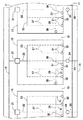
まず、図1に示すように、圃場の内部は、農道11や畦畔12によって複数の耕作区13に区画されており、一方の農道部分には給水路14が設けられ、他方の農道部分には排水路15が設けられるとともに、各耕作区13には、地下灌漑用暗渠装置がそれぞれ設けられている。なお、給水路や排水路は圃場の状況に応じて任意の位置に設けることができ、畦畔の部分に設けられていることもある。また、オープン水路、パイプラインのいずれであってもよい。
【0012】
地下灌漑用暗渠装置は、耕作区13の地中に、給水制御装置21を有する給水管22を介して前記給水路14に接続する給水用集合管23と、排水制御装置24を有する排水管25を介して前記排水路15に接続する排水用集合管26と、両集合管23,26に両端がそれぞれ接続された複数の有孔管(暗渠排水パイプ)27とを、圃場の条件に応じた位置及び深さに埋設したものであって、給水制御装置21及び排水制御装置24を操作することによって各耕作区13の水位を任意に設定できるように形成されている。なお、耕作区13への給排水方法は、従来から行われている各種方式で行うことができ、給水路14、給水制御装置21、給水管22及び排水制御装置24は必須なものではない。
【0013】
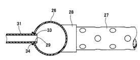
そして、図2及び図3に示すように、排水用集合管26には、前記有孔管27に対向した位置にガイド管31がそれぞれ接続されている。このガイド管31は、ワイヤー等からなるパイプクリーナーを有孔管27の内部に挿入するために設けられるものであって、有孔管27の施工に引き続いて排水用集合管26に接続されるものである。
【0014】
すなわち、図4に示すように、耕作区13の所定位置に排水用集合管26を埋設するための溝41を形成し、この溝41内に排水用集合管26を設置する。このとき、排水用集合管26には、有孔管27を接続するための接続部28と、ガイド管31を接続するための開口29とがあらかじめ設けられており、有孔管27の接続を容易に行えるように、接続部28を上方に向け、開口29を下方に向けた状態で溝内に設置される。なお、接続部28には、あらかじめ有孔管27の一端を接続した状態としておくこともできる。
【0015】
次に、図5に示すように、接続部28を耕作区13の内部側に倒し、有孔管埋設用の溝42内に有孔管27を敷設した後、ガイド管31を接続する部分を除いて籾殻や土砂を用いて前記溝41,42を埋め戻す。そして、図6に示すように、ガイド管31の接続部に相当する部分に穴43を掘削し、ガイド管31を農道11の耕作区13側に設けられた保護箱32内から土中に挿入し、穴43内に突出したガイド管31の先端を排水用集合管26の前記開口29内に挿入して接合する。排水用集合管26へのガイド管31の接続は、ガイド管先端に設けた外面円錐状の係合部33と鍔部34との間に排水用集合管26の管壁を挟み込むようにすることにより、抜けを防止しながら確実な接続状態とすることができる。
【0016】
最後に穴43を埋め戻すことによって排水用集合管26、有孔管27及びガイド管31の設置工事が終了し、ガイド管31の末端を保護箱32内に開口させるとともに先端を排水用集合管26に接続した状態とし、ガイド管31と有孔管27とを排水用集合管26を挟んで対向した状態とすることができる。なお、給水制御装置21や排水制御装置24等の部分は、従来と同様の施工手順で行うことができるので、詳細な説明は省略する。
【0017】
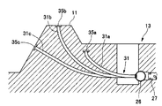
前記保護箱32は、ガイド管31の端部が破損したり、管内に異物が侵入したりすることを防止するためのものであって、ガイド管31内にパイプクリーナーを挿入するときは、蓋35を取り外して行うようにしている。また、ガイド管31の端部には、キャップを取り付けておくこともできる。さらに、ガイド管31の末端の処理は、耕作区13の条件に応じて任意に行うことができる。例えば、図7のガイド管31aに示すように、末端を耕作区13内の地中所定深さまで立ち上げ、開口をキャップ35aで塞いだ状態としておき、使用時にこの部分を掘り起こしてガイド管31aの末端を開口できるようにしておくこともできる。また、ガイド管31bで示すように、農道11や畦畔12の部分に立ち上げてキャップ35bで開口を塞いだ状態にしたり、ガイド管31cで示すように、農道11や畦畔12を貫通させてキャップ35cで開口を塞いだ状態にしたりすることもできる。なお、各キャップは、ガイド管内に異物が侵入することを防止できればよく、簡単な嵌め込み構造としておいてもよいが、ガイド管31cの場合、このガイド管内を通って用水が漏れるおそれがあるときには、プラグ等を使用して密封しておくことができる。
【0018】
また、図1及び図2において中央に位置する有孔管27のように、有孔管27と対向する位置に排水管25が設けられており、排水用集合管26に前述のような開口29を設けられない場合には、図8に示すように、有孔管27の端部からガイド管31を分岐させるようにすることができる。すなわち、前記有孔管27の端部にY型の分岐継手36を設け、この分岐継手36の分岐管部37に前記同様のガイド管31を接続することにより、開口29を設けられない位置の有孔管27内にもパイプクリーナーを挿入可能な状態にすることができる。前記分岐管部37の角度は、ガイド管31から挿入したパイプクリーナーが有孔管27内に進入できる角度であればよく、例えば45度のY型分岐継手を用いることができる。このような分岐継手36を全ての有孔管27に使用することも可能であり、圃場の条件やコストを考慮して選択することができる。また、継手を用いずに有孔管からガイド管31を直接分岐させることもできる。
【0019】
前記排水用集合管26や有孔管27の口径は、各耕作区13の状況に応じて設定されるものであるが、ガイド管31の口径は、このガイド管31内にパイプクリーナーを通すことができればよく、また、ガイド管31から有孔管27へとパイプクリーナーを確実にガイドできるように、排水用集合管26や有孔管27に比べて小口径のパイプを使用することが好ましい。例えば、排水用集合管26の口径(呼径)が75、有孔管27の口径が50に対して、ガイド管31には口径が20程度のものを使用することができる。さらに、各管の材質は、一般的には、排水用集合管26には主として薄肉の塩ビ管が、有孔管27には主としてポリエチレン製有孔管がそれぞれ用いられるが、ガイド管31には、前述のように土中に圧入することを考慮すると、汎用(通常の肉厚)の塩ビ管を使用することが好ましい。
【0020】
なお、溝41,42及び穴43をあらかじめ所定位置に形成してから各管の接続及び敷設を行うようにしてもよく、各管を十文字状の継手を使用して接続するようにしてもよいが、溝や穴が各管の接続部において十文字状に開削された状態になるので、溝の周囲が崩れやすくなるという問題がある。また、異口径の十文字状の継手は汎用品がほとんどないため、部品コストが増大することがある。さらに、ガイド管31の埋設位置全体を開削して行うことも可能であるが、ガイド管31は排水用集合管26や有孔管27に比べて短いので、ガイド管31の先端に適当な治具を装着した状態で保護箱32側から土中に圧入することにより、先端を溝43内に突出させることが可能であり、先端を開口29に接続する際には、溝43内に突出したガイド管31の先端を手で引っ張ることによって簡単にかつ確実にガイド管31と排水用集合管26とを接続することができる。
【0021】
このようなガイド管31を設けて各有孔管27内にパイプクリーナーを挿入可能に形成することにより、有孔管27内を簡単に清掃することが可能となるので、有孔管27内の清掃を適当な時期に行うことにより、有孔管27に土砂等が詰まって給排水不能な状態になることを未然に防止することができる。また、有孔管27が閉塞してしまったようなときでも、パイプクリーナーによって閉塞物を除去することが可能であり、有孔管27における暗渠排水パイプとしての機能を長期間維持することができる。さらに、ガイド管31の他端開口を各耕作区13の内側部分に立ち上げて開口させることにより、農道11や畦畔12を崩すことなくガイド管31を設置することができるので、工事費の削減を図れるとともに、ガイド管設置部からの用水の漏洩も生じることがない。
【0022】
また、前述のようなガイド管は、有孔管27の給水側(反排水側)に設けることも可能であるが、有孔管27内に大量の土砂等が蓄積してしまったときには、パイプクリーナーを用いても、これらを排水側に排出することが困難であり、有孔管27内の清掃を確実に行えなくなるときがある。また、給水側にガイド管を設置した場合は、ガイド管を通って有孔管27内に空気が流入することがあるため、鉄分を多く含む用水の場合には有孔管27内に鉄さびが付着することがある。一方、前述のように、排水側にガイド管31を設置した場合は、このガイド管31を通って空気が流入しても、有孔管27内に侵入することなく直ちに排水用集合管26から排水管25に排出されるので、有孔管27内で鉄分が酸化することはほとんどない。
【0023】
さらに、図1に想像線で示すように、排水用集合管26の端部にも前記同様のガイド管38を設けておくことにより、排水用集合管26の内部もパイプクリーナーによって清掃することができる。また、排水用集合管26に清掃時排水用の予備排水管39を設けておき、パイプクリーナーによる清掃時に、弁40を開いて予備排水管39から洗浄排水を排出することにより、土砂等を多く含む水が排水制御装置24に流入することを防止できる。このとき、ガイド管31から有孔管27内にパイプクリーナーを挿入する際には、弁40を閉じて有孔管27内を満流状態にしておくことにより、有孔管27内で土砂等が固まることを防止できるので、パイプクリーナーの挿入を容易に行うことができ、パイプクリーナーを十分に挿入してから弁40を開くことにより、有孔管27内の水と共に土砂等を効果的に排出することができる。
【0024】
本形態例では、各耕作区の地中に埋設した有孔管によって給排水を行う地下灌漑設備を例示して説明したが、有孔管を排水路にのみ接続し、前記排水制御装置により、あるいは排水路の水位を調節することにより、各耕作区内の水位を設定する暗渠排水設備にも適用できる。
【0025】
【発明の効果】
以上説明したように、本発明によれば、圃場の地中に埋設した有孔管(暗渠排水パイプ)内の清掃を簡単に行うことができるので、有孔管が土砂等によって閉塞してしまうことを防止でき、また、閉塞してしまった場合でも、これらを容易に除去することができる。
【図面の簡単な説明】
【図1】本発明の地下灌漑用暗渠装置における配管系統の一形態例を示す概略平面図である。
【図2】排水側の配管接続状態を示す要部の平面図である。
【図3】ガイド管の接続状態を示す断面図である。
【図4】集合管設置時の状態を示す断面図である。
【図5】有孔管設置時の状態を示す断面図である。
【図6】ガイド管接続時の状態を示す断面図である。
【図7】ガイド管の他の設置例を示す断面図である。
【図8】ガイド管と有孔管との他の接続状態を示す断面図である。
【符号の説明】
11…農道、12…畦畔、13…耕作区、14…給水路、15…排水路、21…給水制御装置、22…給水管、23…給水用集合管、24…排水制御装置、25…排水管、26…排水用集合管、27…有孔管(暗渠排水パイプ)、28…接続部、29…開口、31…ガイド管、32…保護箱、33…係合部、34…鍔部、35…蓋、36…分岐継手、37…分岐管部、38…ガイド管、39…予備排水管、40…弁、41,42…溝、43…穴[0001]
TECHNICAL FIELD OF THE INVENTION
The present invention relates to a culvert device for underground irrigation and a method for forming the same, and in particular, by using a perforated pipe buried in the ground of a field to supply and drain water, the water level in the field is set to a predetermined height. And a method for forming the same.
[0002]
[Prior art]
Underground irrigation (underdrainage), which has been under way in recent years, uses a culvert drainage pipe consisting of a perforated pipe buried in the ground of a field to maintain the water level in the field at an optimum level according to the type and growth state of the crop The culvert drainage pipe is connected to the water supply channel and the drainage channel, and the culvert drainage pipe can be connected to the water supply channel and the drainage channel to effectively supply and drain water to the field. So-called underground irrigation is being carried out as described above (for example, see Patent Document 1).
[0003]
[Patent Document 1]
JP-A-10-155375 (
[0004]
[Problems to be solved by the invention]
Underground irrigation (including culvert drainage) as described above, depending on the local conditions of the field, the irrigation water may contain a large amount of trash and sediment. There is a possibility that the water accumulates in the pipe and impairs the water flow performance. Therefore, when using irrigation water containing a large amount of soil and the like for underground irrigation, it was necessary to install a fine filter at the connection of the culvert drainage pipe. However, if such measures are taken, maintenance requires much labor. In the case of service water containing a large amount of iron, if air enters the culvert drainage pipe, the iron may be oxidized and adhere to the inner surface of the pipe.
[0005]
Therefore, the present invention can easily clean the inside of a perforated pipe even when sediment or the like settles and accumulates in a perforated pipe such as a culvert drainage pipe, and can easily perform construction of a culvert facility. It is an object of the present invention to provide a culvert device for underground irrigation and a method for forming the same.
[0006]
[Means for Solving the Problems]
In order to achieve the above object, the underground irrigation culvert apparatus of the present invention connects one end of a plurality of perforated pipes buried in the ground of a field to a collecting pipe, and connects the collecting pipe to a drain pipe leading to a drainage channel. In the connected irrigation culvert device, a guide pipe for guiding a pipe cleaner toward each perforated pipe is connected to a position of the collecting pipe facing the perforated pipe connection portion, and It is characterized in that it can be opened to the ground by raising the other end.
[0007]
In another aspect of the underground irrigation culvert device of the present invention, one end of a plurality of perforated pipes buried underground in a field is connected to a collecting pipe, and the collecting pipe is connected to a drain pipe leading to a drainage channel. In the connected irrigation culvert device, a guide pipe for guiding a pipe cleaner toward the inside of the perforated pipe is branched from an end of the perforated pipe, and the other end of the guide pipe is raised and opened to the ground. It is made possible.
[0008]
Further, in both of the above aspects, the perforated pipe is characterized in that the pipe can be maintained in a full-flow state when the pipe cleaner is inserted from the guide pipe.
[0009]
The method of forming an underground irrigation culvert device according to the present invention is the method of forming an underground irrigation culvert device according to
[0010]
BEST MODE FOR CARRYING OUT THE INVENTION
FIG. 1 shows an embodiment of an underground irrigation culvert device of the present invention. FIG. 1 is a schematic plan view showing a piping system in an underground irrigation culvert device, and FIG. FIG. 3 is a sectional view showing a connected state of the guide tube. 4 is a cross-sectional view showing a state when a collecting pipe is installed, FIG. 5 is a cross-sectional view showing a state when a perforated pipe is installed, FIG. 6 is a cross-sectional view showing a state when a guide pipe is connected, and FIG. FIG. 8 is a cross-sectional view showing another connection state between the guide pipe and the perforated pipe.
[0011]
First, as shown in FIG. 1, the inside of the field is divided into a plurality of
[0012]
The underground irrigation culvert device includes a water
[0013]
As shown in FIGS. 2 and 3,
[0014]
That is, as shown in FIG. 4, a
[0015]
Next, as shown in FIG. 5, the connecting
[0016]
Finally, the
[0017]
The
[0018]
1 and 2, a
[0019]
The diameters of the
[0020]
The
[0021]
By providing such a
[0022]
Further, the above-described guide tube can be provided on the water supply side (anti-drainage side) of the
[0023]
Further, as shown by an imaginary line in FIG. 1, by providing a guide tube 38 similar to the above at the end of the
[0024]
In the present embodiment, the underground irrigation equipment for supplying and draining water with perforated pipes buried in the ground of each cultivation area has been described as an example, but perforated pipes are connected only to drainage channels, and the drainage control device or By adjusting the water level of the drainage channel, it can also be applied to culvert drainage equipment that sets the water level in each cultivated area.
[0025]
【The invention's effect】
As described above, according to the present invention, it is possible to easily clean the inside of a perforated pipe (underdrainage drain pipe) buried underground in a field, so that the perforated pipe is blocked by soil and the like. Can be prevented, and even if they are blocked, they can be easily removed.
[Brief description of the drawings]
FIG. 1 is a schematic plan view showing one embodiment of a piping system in an underground irrigation culvert device of the present invention.
FIG. 2 is a plan view of a main part showing a pipe connection state on a drain side.
FIG. 3 is a sectional view showing a connection state of a guide tube.
FIG. 4 is a cross-sectional view showing a state when a collecting pipe is installed.
FIG. 5 is a cross-sectional view showing a state when a perforated pipe is installed.
FIG. 6 is a cross-sectional view showing a state when a guide tube is connected.
FIG. 7 is a sectional view showing another installation example of the guide tube.
FIG. 8 is a sectional view showing another connection state between the guide tube and the perforated tube.
[Explanation of symbols]
DESCRIPTION OF
Claims (4)
Priority Applications (1)
| Application Number | Priority Date | Filing Date | Title |
|---|---|---|---|
| JP2003035031A JP3756157B2 (en) | 2003-02-13 | 2003-02-13 | Underdrain irrigation apparatus and method for forming the same |
Applications Claiming Priority (1)
| Application Number | Priority Date | Filing Date | Title |
|---|---|---|---|
| JP2003035031A JP3756157B2 (en) | 2003-02-13 | 2003-02-13 | Underdrain irrigation apparatus and method for forming the same |
Publications (2)
| Publication Number | Publication Date |
|---|---|
| JP2004244893A true JP2004244893A (en) | 2004-09-02 |
| JP3756157B2 JP3756157B2 (en) | 2006-03-15 |
Family
ID=33020563
Family Applications (1)
| Application Number | Title | Priority Date | Filing Date |
|---|---|---|---|
| JP2003035031A Expired - Lifetime JP3756157B2 (en) | 2003-02-13 | 2003-02-13 | Underdrain irrigation apparatus and method for forming the same |
Country Status (1)
| Country | Link |
|---|---|
| JP (1) | JP3756157B2 (en) |
Cited By (7)
| Publication number | Priority date | Publication date | Assignee | Title |
|---|---|---|---|---|
| JP2006238809A (en) * | 2005-03-04 | 2006-09-14 | International Nature Farming Research Center | Underdrainage apparatus for subirrigation drainage |
| JP2012095621A (en) * | 2010-11-04 | 2012-05-24 | Paddy Research Co Ltd | Underground irrigation system |
| JP2012205571A (en) * | 2011-03-30 | 2012-10-25 | National Agriculture & Food Research Organization | Water management system for farmland |
| WO2014203421A1 (en) * | 2013-06-16 | 2014-12-24 | 西日本圃場改良株式会社 | Underground irrigation system |
| JP2015008661A (en) * | 2013-06-27 | 2015-01-19 | 西日本圃場改良株式会社 | Conduit body for field |
| JP2015023879A (en) * | 2014-11-07 | 2015-02-05 | 西日本圃場改良株式会社 | Underground irrigation system |
| CN109452139A (en) * | 2018-12-29 | 2019-03-12 | 华北水利水电大学 | A kind of compound infiltrating irrigation pipe of flushable oxygenation |
Families Citing this family (1)
| Publication number | Priority date | Publication date | Assignee | Title |
|---|---|---|---|---|
| JP5712410B2 (en) * | 2013-08-19 | 2015-05-07 | 西日本圃場改良株式会社 | Water level adjuster |
-
2003
- 2003-02-13 JP JP2003035031A patent/JP3756157B2/en not_active Expired - Lifetime
Cited By (7)
| Publication number | Priority date | Publication date | Assignee | Title |
|---|---|---|---|---|
| JP2006238809A (en) * | 2005-03-04 | 2006-09-14 | International Nature Farming Research Center | Underdrainage apparatus for subirrigation drainage |
| JP2012095621A (en) * | 2010-11-04 | 2012-05-24 | Paddy Research Co Ltd | Underground irrigation system |
| JP2012205571A (en) * | 2011-03-30 | 2012-10-25 | National Agriculture & Food Research Organization | Water management system for farmland |
| WO2014203421A1 (en) * | 2013-06-16 | 2014-12-24 | 西日本圃場改良株式会社 | Underground irrigation system |
| JP2015008661A (en) * | 2013-06-27 | 2015-01-19 | 西日本圃場改良株式会社 | Conduit body for field |
| JP2015023879A (en) * | 2014-11-07 | 2015-02-05 | 西日本圃場改良株式会社 | Underground irrigation system |
| CN109452139A (en) * | 2018-12-29 | 2019-03-12 | 华北水利水电大学 | A kind of compound infiltrating irrigation pipe of flushable oxygenation |
Also Published As
| Publication number | Publication date |
|---|---|
| JP3756157B2 (en) | 2006-03-15 |
Similar Documents
| Publication | Publication Date | Title |
|---|---|---|
| JP3756157B2 (en) | Underdrain irrigation apparatus and method for forming the same | |
| KR101238872B1 (en) | Drainage pipe for cultivation area and method for installing the same | |
| JP2004180529A (en) | Underground irrigation system | |
| JP2001173028A (en) | Manchurian well type water collecting method and it water buried collecting conduit device | |
| JP3671373B2 (en) | Underground irrigation system | |
| KR100970339B1 (en) | Raising the ground level preventing flood damage | |
| KR20060063827A (en) | Prefabricated drainage pipe and rapid drainage method using the same | |
| JP4544611B2 (en) | Water level adjustment system | |
| JP2006238809A (en) | Underdrainage apparatus for subirrigation drainage | |
| KR100450602B1 (en) | Drainage apparatus of slope for road | |
| JP3535663B2 (en) | Rain water | |
| JPH0447246Y2 (en) | ||
| JPS6227537Y2 (en) | ||
| JPH0447247Y2 (en) | ||
| US6402963B2 (en) | Draining wall | |
| JP2005299904A (en) | Culvert | |
| JP3716022B2 (en) | Branch gate valve | |
| JP3162563B2 (en) | Variable flow path drainage basin and method of switching the drainage basin | |
| JPH08261362A (en) | Preplacing method for sewer pipe device | |
| KR200300282Y1 (en) | Filtration device for manhole | |
| JPH08277570A (en) | Temporary burying method of public drop inlet, method of constructing sewarage and structure of sewarage facility | |
| KR200301122Y1 (en) | underdrain | |
| JPS6112049B2 (en) | ||
| JP2815511B2 (en) | Drainage basin | |
| CN109577293A (en) | A kind of integration irrigation and drainage pipe-line system and construction method |
Legal Events
| Date | Code | Title | Description |
|---|---|---|---|
| A977 | Report on retrieval |
Free format text: JAPANESE INTERMEDIATE CODE: A971007 Effective date: 20050722 |
|
| A131 | Notification of reasons for refusal |
Free format text: JAPANESE INTERMEDIATE CODE: A131 Effective date: 20050809 |
|
| A521 | Request for written amendment filed |
Free format text: JAPANESE INTERMEDIATE CODE: A523 Effective date: 20051007 |
|
| TRDD | Decision of grant or rejection written | ||
| A01 | Written decision to grant a patent or to grant a registration (utility model) |
Free format text: JAPANESE INTERMEDIATE CODE: A01 Effective date: 20051206 |
|
| A61 | First payment of annual fees (during grant procedure) |
Free format text: JAPANESE INTERMEDIATE CODE: A61 Effective date: 20051220 |
|
| R150 | Certificate of patent or registration of utility model |
Ref document number: 3756157 Country of ref document: JP Free format text: JAPANESE INTERMEDIATE CODE: R150 Free format text: JAPANESE INTERMEDIATE CODE: R150 |
|
| S111 | Request for change of ownership or part of ownership |
Free format text: JAPANESE INTERMEDIATE CODE: R313115 |
|
| R350 | Written notification of registration of transfer |
Free format text: JAPANESE INTERMEDIATE CODE: R350 |
|
| FPAY | Renewal fee payment (event date is renewal date of database) |
Free format text: PAYMENT UNTIL: 20100106 Year of fee payment: 4 |
|
| R250 | Receipt of annual fees |
Free format text: JAPANESE INTERMEDIATE CODE: R250 |
|
| FPAY | Renewal fee payment (event date is renewal date of database) |
Free format text: PAYMENT UNTIL: 20110106 Year of fee payment: 5 |
|
| R250 | Receipt of annual fees |
Free format text: JAPANESE INTERMEDIATE CODE: R250 |
|
| FPAY | Renewal fee payment (event date is renewal date of database) |
Free format text: PAYMENT UNTIL: 20120106 Year of fee payment: 6 |
|
| R250 | Receipt of annual fees |
Free format text: JAPANESE INTERMEDIATE CODE: R250 |
|
| FPAY | Renewal fee payment (event date is renewal date of database) |
Free format text: PAYMENT UNTIL: 20120106 Year of fee payment: 6 |
|
| FPAY | Renewal fee payment (event date is renewal date of database) |
Free format text: PAYMENT UNTIL: 20130106 Year of fee payment: 7 |
|
| R250 | Receipt of annual fees |
Free format text: JAPANESE INTERMEDIATE CODE: R250 |
|
| FPAY | Renewal fee payment (event date is renewal date of database) |
Free format text: PAYMENT UNTIL: 20130106 Year of fee payment: 7 |
|
| R250 | Receipt of annual fees |
Free format text: JAPANESE INTERMEDIATE CODE: R250 |
|
| R250 | Receipt of annual fees |
Free format text: JAPANESE INTERMEDIATE CODE: R250 |
|
| R250 | Receipt of annual fees |
Free format text: JAPANESE INTERMEDIATE CODE: R250 |
|
| S533 | Written request for registration of change of name |
Free format text: JAPANESE INTERMEDIATE CODE: R313533 |
|
| R350 | Written notification of registration of transfer |
Free format text: JAPANESE INTERMEDIATE CODE: R350 |
|
| R250 | Receipt of annual fees |
Free format text: JAPANESE INTERMEDIATE CODE: R250 |
|
| R250 | Receipt of annual fees |
Free format text: JAPANESE INTERMEDIATE CODE: R250 |
|
| R250 | Receipt of annual fees |
Free format text: JAPANESE INTERMEDIATE CODE: R250 |
|
| R250 | Receipt of annual fees |
Free format text: JAPANESE INTERMEDIATE CODE: R250 |
|
| R250 | Receipt of annual fees |
Free format text: JAPANESE INTERMEDIATE CODE: R250 |
|
| R250 | Receipt of annual fees |
Free format text: JAPANESE INTERMEDIATE CODE: R250 |
|
| R250 | Receipt of annual fees |
Free format text: JAPANESE INTERMEDIATE CODE: R250 |
|
| R250 | Receipt of annual fees |
Free format text: JAPANESE INTERMEDIATE CODE: R250 |
|
| EXPY | Cancellation because of completion of term |