JP2004244188A - Elevator car - Google Patents
Elevator car Download PDFInfo
- Publication number
- JP2004244188A JP2004244188A JP2003036951A JP2003036951A JP2004244188A JP 2004244188 A JP2004244188 A JP 2004244188A JP 2003036951 A JP2003036951 A JP 2003036951A JP 2003036951 A JP2003036951 A JP 2003036951A JP 2004244188 A JP2004244188 A JP 2004244188A
- Authority
- JP
- Japan
- Prior art keywords
- apron
- elevator car
- floor
- car
- sill
- Prior art date
- Legal status (The legal status is an assumption and is not a legal conclusion. Google has not performed a legal analysis and makes no representation as to the accuracy of the status listed.)
- Pending
Links
Images


Abstract
Description
【0001】
【発明の属する技術分野】
本発明は、エプロンを有するエレベータかごに係り、とりわけエプロン下方の空間を利用することができるエレベータかごに関する。
【0002】
【従来の技術】
従来よりエレベータかごの停止時において着床誤差が大きい場合に、乗客等が昇降路内へ転落しないよう、エレベータかご床の出入口の敷居下部にエプロンが設けられている。
【0003】
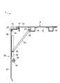
次に図10および図11により、従来のエレベータかごのエプロンについて説明する。このうち図10はエレベータかご7のかご床8の前端部を示している。
【0004】
図10において、かご床8の前端部は、かご床8の表面を形成している床仕上材14と、床仕上剤14の下部に配設された床材15と、床材15の下面に紙面に直交して設けられた複数の床補強16とを有している。かご床8の最前端部の床材15の下部に敷居受け17が設けられ、敷居受け17の上部に敷居18が設けられている。また敷居18の下部に位置する敷居受け17に、溶接ナット19とボルト20を介してエプロン21が設けられている。さらに最前側の床補強16の前側に振れ止め部材取付部22が設けられ、エプロン21の折り曲げ部25と振れ止め部材取付部22とは、ボルト23を介して取付けられた振れ止め部材24により連結されている。
【0005】
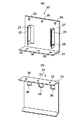
図11は、エプロン21の斜視図である。図11において、エプロン21には、その上部に一列に配置された複数のだるま穴26と、高さ方向中央部に形成された折り曲げ部25とが設けられている。また折り曲げ部25の切欠き部分に高さ方向に長い形状をした貫通穴27が形成されるとともに、折り曲げ部25の下部に振れ止め部材23を連結するため溶接ナット28が取り付けられている。
【0006】
【発明が解決しようとする課題】
しかしながら、上記のような従来のエレベータかごでは、近年のバリアフリー化に伴う公共設備、例えば駅舎等へのエレベータ設置の需要が増加する中で、以下のような課題がある。
【0007】
既存の駅舎にエレベータを増設するという条件より、駅舎エレベータは、最下階が改札口階で最上階がホーム階のような2方向出入口の仕様を有している。最下階と最上階の行程差である階高がきわめて低い場合、作業員が昇降路最下部にあたるピットに入り作業するとき、敷居下部にエプロンがある為に、作業員がピットへ侵入可能な空間が確保されていない。この場合、作業員は敷居18とエプロン21の締結部のボルト20を緩め、またエプロン21とかご床8を連結している振れ止め部材24の締結部のボルト23を取り外し、かご床8からエプロン21全体を取り外してエプロン21下方の空間を確保した後にピットに侵入している。
【0008】
また、最上階にエレベータかごが停止した際、作業員がピットでの作業を完了し、ピットから乗場に出る場合、敷居受け17に溶接ナット19が取付けられているので、敷居18とエプロン21とを締結しているボルト20は、乗り場側から容易に取り外すことが出来るが、ピット内から取り外すことが不可能である。その結果、作業員はピットからエプロン21を取り外すことができず、エプロン21下方の空間が確保されていない為、作業員は一人でピットから乗場へ出ることが困難である。
【0009】
このような課題を解決する為、エプロンを上下に伸縮できるような機構として、特開2002−179368のダブルデッキエレベータのエプロン階間調整が考えられる。このようなダブルデッキエレベータのエプロンは、上側エレベータのかご床の敷居と、下側エレベータのかご天井に連結され、上下両方のエレベータかごの動作とリンクしているため、エプロンが上下に伸縮でき、階高の違いによるエプロンの高さを調整するものである。しかしながら、この発明は、あくまで上下にエレベータかごにエプロン及び整風板を固設し、エレベータかごを上下駆動装置により移動させてエプロン階間調整を行うものであり、エプロンの高さ調整を行うため、大型の駆動装置を必要としている。
【0010】
本発明はこのような点を考慮してなされたものであり、エプロンを上下に伸縮できるような大型の駆動装置を必要とせず、乗場側とピット内の両方からエプロン下方の空間を容易に確保でき、安価で作業性を向上することが出来るエレベータかごを提供することを目的とする。
【0011】
【課題を解決するための手段】
本発明は、エレベータかごにおいて、かご床と、前記かご床の前端に敷居受けを介して設けられた敷居と、前記敷居受けに設けられたエプロンとを備え、前記エプロンは上下に分割した上部エプロンと下部エプロンとからなり、前記上部エプロンと前記下部エプロンはチョウボルトおよびナットにより締結され、前記かご床と前記上部エプロンとは振れ止め部材により連結され、前記下部エプロンのうちチョウボルト及びナットの締結箇所近傍に第1開口穴を形成したことを特徴とするエレベータかごである。
【0012】
本発明によれば、エプロンを上部エプロンと下部エプロンとに分割したことにより、第1開口穴を介して乗場から、またはピットからチョウボルトを取り外し下部エプロンを容易に取り外すことができ、エプロン下方の空間を確保することができる。
【0013】
本発明は、前記上部エプロンにチョウボルトに当接するリミットSWを設け、前記チョウボルトをナットから取外した場合、前記リミットSWが動作することを特徴とするエレベータかごである。
【0014】
本発明によれば、リミットSWを設けたことにより、エレベータかごの不用意な動きに対し、作業員に対する安全性を高めることができる。また、乗場またはピットから下部エプロンを容易に取り外すことができ、エプロン下方の空間を確保することができる。
【0015】
本発明は、前記下部エプロンに横方向に細長く延びる第2開口穴を形成したことを特徴とするエレベータかごである。
【0016】
本発明によれば、第2開口穴を利用し、下部エプロンの取り外し作業を容易にすることができ、乗場またはピットから下部エプロンを容易に取り外して、エプロン下方の空間を確保することができる。
【0017】
本発明は、前記敷居受けの側面に前記エプロンを両側方から支持する案内部材を設け、前記エプロンは上部エプロンと下部エプロンとの間に位置する中間エプロンを有し、下部エプロンおよび中間エプロンに、横方向に細長く延びる第2開口穴および第3開口穴を各々設け、下部エプロンおよび中間エプロンは、案内部材に沿って移動可能となることを特徴とするエレベータかごである。
【0018】
本発明によれば、各エプロンが案内部材に沿って移動することができるので、乗り場またはピットから第2開口穴および第3開口穴を利用して任意のエプロンを上下に移動でき、エプロン下方の空間を確保することができる。
【0019】
本発明は、エレベータかごにおいて、かご床と、前記かご床の前端に敷居受けを介して設けられた敷居と、前記敷居受けに設けられたエプロンとを備え、前記エプロンは上部エプロンと、下部エプロンと、上部エプロンと下部エプロンとの間に位置する複数の中間エプロンとからなり、上部エプロン、下部エプロンおよび各中間エプロンは互いに蝶番により連結され、前記かご床と前記下部エプロンとは振れ止め部材により連結され、前記下部エプロンのうち振れ止め部材近傍に、第4開口穴を設けたことを特徴とするエレベータかごである。
【0020】
本発明によれば、蝶番を介して連結された各エプロンを乗場またはピットから蛇腹状に畳み込むことができるので、エプロン下方の空間を確保することができる。
【0021】
本発明は、エレベータかごにおいて、かご床と、前記かご床の前端に敷居受けを介して設けられた敷居と、前記敷居受けに設けられたエプロンとを備え、前記エプロンは上部エプロンと、下部エプロンと、上部エプロンと下部エプロンとの間に位置する複数の中間エプロンとからなり、上部エプロン、下部エプロンおよび各中間エプロンは互いに摺動自在に連結されるとともに、パンタグラフ機構により駆動され、前記かご床と前記下部エプロンとは振れ止め部材により連結されることを特徴とするエレベータかごである。
【0022】
本発明によれば、各エプロンをパンタグラフ機構により、乗場またはピットから上下に移動できるので、エプロン下方の空間を確保することができる。
【0023】
【発明の実施の形態】
第1の実施の形態
以下、図面を参照して本発明の実施の形態について説明する。
図1、図2および図9により、本発明によるエレベータかごの第1の実施の形態について説明する。
【0024】
まず図9により、エレベータ全体について説明する。
図9は、階床数が2つの2方向の出入口を有するエレベータ全体の縦断面を示している。
【0025】
図9において、エレベータは、建屋内に垂直な空間として形成される昇降路1と、昇降路1の最下部空間を構成しているピット2と、昇降路1の建屋垂直方向と平行に設置されたレール3と、昇降路1内をレール3に沿って移動するエレベータかご7とを備えている。
【0026】
レール3の上部に巻上機4が配置され、巻上機4にメインロープ5が巻き付けられている。メインロープ5の一端にカウンターウェイト6が設けられるとともに、メインロープ5の他端に本発明によるエレベータかご7が設けられている。
【0027】
このうち、本発明によるエレベータかご7は、下部に設置されたかご床8と、かご床8の上部に立設したかご室9とを備えている。また、最下階10の出入口には最下階乗場ドア11が設置され、最上階12の出入口には最上階乗場ドア13が設置されている。
【0028】
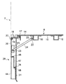
次に、図1および図2により、エレベータかご7のかご床8について詳述する。このうち図1はエレベータかご7のかご床8の前端部を示す図である。
【0029】
図1において、かご床8は、かご床8の表面を形成している床仕上材14と、床仕上材14の下部に配設された床材15と、床材15の下面に紙面に直交して設けられた複数の床補強16とを有している。かご床8の最前端部の床材15の下部に敷居受け17が設けられ、敷居受け17の上部に敷居18が設けられている。また敷居18の下部の敷居受け17に、溶接ナット19とボルト20を介してエプロン29が設けられている。
【0030】
さらに最前側の床補強16の前側に、振れ止め部材取付部22が設けられ、これ振れ止め部材取付部22にボルト23により振れ止め部材24が連結されている。
【0031】
またエプロン29は、上部エプロン30と下部エプロン31に分割され、このうち上部エプロン30は、上記の振れ止め部材24にボルト23により連結され、このようにして敷居受け17と上部エプロン30は振れ止め部材24を介して互いに連結されている。さらに、下部エプロン31の上面は、上部エプロン30の下面と接触し、上部エプロン30と下部エプロン31はチョウボルト32とナット33により締結されている。
【0032】
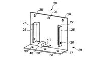
図2は、エプロン29の斜視図を示している。このうち図2(a)は、上部エプロン30を、図2(b)は、下部エプロン31を各々示している。
【0033】
図2(b)において、下部エプロン31の上側には折り曲げ部34が形成され、折り曲げ部34には、上部エプロン30と締結する為の穴35が形成されている。下部エプロン31の上側の穴35の近傍位置には、第1開口穴36が設けられている。図2(a)において、上部エプロン30の下側には折り曲げ部37が形成され、折り曲げ部37には、下部エプロン31と締結する為の穴38が形成されている。
【0034】
また、上部エプロン30には、その上部に一列に配置された複数のだるま穴26と、高さ方向中央部に形成された折り曲げ部25とが設けられている。また折り曲げ部25の切欠き部分に高さ方向に長い形状をした貫通穴27が形成されるとともに、折り曲げ部25の下部に溶接ナット28が取付けられ、振れ止め部材24はボルト23を溶接ナット28に嵌込むことより上部エプロン30に固定される。
【0035】
次にこのような構成からなる本実施の形態の作用について説明する。
作業員が保守点検作業を行う場合、乗り場10,12からは第1開口穴36を利用して締結されたチョウボルト32を取り外し、ピットからは直にチョウボルト32を取り外す。このことにより、下部エプロン31を上部エプロン30から取り外すことができる。このため乗場またはピットから下部エプロン31を容易に取り外すことができ、エプロン下方の空間を確保することができる。
【0036】
第2の実施の形態
次に本発明による第2の実施の形態について図3により説明する。図3において、図1、図2および図9に示す第1の実施の形態と同一部分には同一符号を付けて詳細な説明は省略する。
【0037】
図3において、エプロン29の上部エプロン30の折り曲げ部37に、リミットSW40が設けられている。他は図1、図2および図9に示す第1の実施の形態と略同一である。
【0038】
通常は、上部エプロン30と下部エプロン31は、折り曲げ部37,34の穴38,35に挿入された複数のチョウボルト32とナット33により締結されている(図1および図2参照)。
【0039】
リミットSW40は、中央に位置したチョウボルト32により、リミットSWレバー41が押し上げられて接点が入る様になっている。
【0040】
図3において、下部エプロン31を上部エプロン30から取り外す時に、図1に示すチョウボルト32を取り外すと、リミットSWレバー41が下がり、リミットSW40の接点が切れた状態となる。
【0041】
リミットSW40の接点が切れると、巻上機4のブレーキが作動し、エレベータかご7は昇降できないので、作業員に対する安全性を高めることができる。この場合、乗場10,12またはピット2から下部エプロン31を容易に取り外すことができ、エプロン下方の空間を確保することができる。
【0042】
第3の実施の形態
次に本発明による第3の実施の形態について図4により説明する。図4において、図1,図2および図9に示す第1の実施の形態と同一部分には同一符号を付けて詳細な説明は省略する。
【0043】
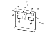
図4において、エプロン29の下部エプロン31には、下部エプロン31の任意の場所に複数の横方向に細長く延びる第2開口穴43が形成されている。他は図1,図2および図9に示す第1の実施の形態と略同一である。
【0044】
図4において、下部エプロン31を上部エプロン30から取り外す際、作業者は第2開口穴43に手を入れる事が出来るため、下部エプロン31の取り外し作業が容易になり、作業性が向上する。また第2開口穴43により作業者が下部エプロン31を支持することができ、下部エプロン31の落下の危険性を防止でき、安全性を高めることができる。このため作業者は安全かつ容易に作業ができ、エプロン下方の空間を確保することができる。
【0045】
第4の実施の形態
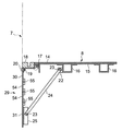
次に本発明による第4の実施の形態について図5により説明する。図5において、図1,図2および図9に示す第1の実施の形態と同一部分には同一符号を付けて詳細な説明は省略する。
【0046】
図5に示すようにかご床8の前端部において、敷居受け17の側面に一対の案内部材44が設けられ、この一対の案内部材44の内側には、複数に分割されたエプロン29が摺動自在に支持されいる。
【0047】
すなわちエプロン29は、上部エプロン30と、下部エプロン31と、上部エプロン30と下部エプロン31との間に位置する中間エプロン47とを有している。このうち上部エプロン30は、図1の上部エプロン30と同様の構成により、振れ止め部材24によってかご床8に固設されている。中間エプロン47の上下部には、折り曲げ部48が形成され、下部エプロン31の上部には、折り曲げ部34が形成されている。
【0048】
下部エプロン31と中間エプロン47には、図5の図面上では図示されていないが、図4に示すエプロン29と同様、任意の場所に複数の横方向に細長い第2開口穴および第3開口穴が各々形成されている(図4参照)。
【0049】
図5において、作業者は、下部エプロン31および中間エプロン47の第2開口穴および第3開口穴に手を入れ、下部エプロン31と中間エプロン47を案内部材44に沿って、上下に移動する。このため、作業が容易になり、作業性が向上する。またエプロン29の中間エプロン47および下部エプロン30に各々折り曲げ部48,34を設けたことにより、エプロン29の落下を防止することができ、安全性を向上することができる。このため作業者は安全且つ容易に作業ができ、エプロン下方の空間を確保することができる。
【0050】
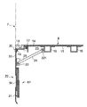
第5の実施の形態
次に本発明による第5の実施の形態について、図6により説明する。図6において、図1,図2および図9に示す第1の実施の形態と同一部分には同一符号を付けて詳細な説明は省略する。
【0051】
図6において、エプロン29は上部エプロン30と、下部エプロン31と、上部エプロン30と下部エプロン31との間に位置する複数の中間エプロン54とを有している。このうち上部エプロン30の下側と、下部エプロン31の上側と、複数の中間エプロン54の上下側には蝶番55が取り付けられ、上部エプロン30、下部エプロン31、中間エプロン54は互いに連結されている。また、下部エプロン31は、図2(a)に示す上部エプロン30と同様に、折り曲げ部25と貫通穴27と溶接ナット28とを有している。このためエプロン29の下部エプロン31とかご床8の間を、ボルト23,23により固定された振れ止め部材24により互いに連結することができる。
【0052】
図6において、ボルト23を取り外して下部エプロン31から振れ止め部材24を取り外す。次に下部エプロン31と中間エプロン54とを蛇腹状に上方向に容易に畳み込む。この場合、エプロン29の上部エプロン30、下部エプロン31および中間エプロン54はかご床8に固設されている為、完全に落下せず、安全性を向上することができる。作業者は安全且つ容易に作業ができ、エプロン下方の空間を確保することができる。
【0053】
第6の実施の形態
次に本発明による第6の実施の形態について図7および図8により説明する。図7および図8において、図1、図2および図9に示す第1の実施の形態と同一部分には同一符号を付けて説明する。
【0054】
図7において、エプロン29は上部エプロン30と、下部エプロン31と、上部エプロン30と下部エプロン31との間に位置する複数の中間エプロン54とを有している。上部エプロン30と中間エプロン54と下部エプロン31は、パンタグラフ機構61により連結されている。
【0055】
図8はエプロン29の背面を示している。図8において、パンタグラフ機構62は、対向配置された一対のくの字状からなるリンク62を有している。リンク62は上下各両端部において上部エプロン30と、下部エプロン31に回転自在に軸支され、中心軸63において中間エプロン54に設けられたレール64に沿って横方向に摺動するようになっている。
【0056】
各リンク62の交叉点には、交叉したアーム66を係止するピン65が取付けられており、このピン65は各アーム66の長さ方向に設けられたスリット67に沿い移動できる。また下部エプロン31には、図4の第2開口穴43と同様な第2開口穴43が設けられている。さらに上部エプロン30には図2(a)の上部エプロン30と同様、折り曲げ部25と、貫通穴27と、溶接ナット28とが設けられている。
【0057】
図7および図8において、エプロン29の上部エプロン30、下部エプロン31、中間エプロン54は、互いにパンタグラフ機構61により連結され、かご床8に固設されている。このため上部エプロン30、下部エプロン31および中間エプロン54は、完全に落下せず、安全性を向上することができる。作業者は、第2開口穴43を利用することにより、下部エプロン31、中間エプロン54を上方向に上げることが可能である。作業者は安全且つ容易に作業ができ、エプロン下方の空間を確保することができる。
【0058】
【発明の効果】
以上説明したように本発明によれば、大型の駆動装置を必要とせず、作業者は安全且つ容易に作業ができ、エプロン下方の空間を確保することができる。
【図面の簡単な説明】
【図1】本発明によるエレベータかごの第1の実施の形態を説明するためのかご床の前端部を示す図。
【図2】本発明によるエレベータかごの第1の実施の形態を説明するためのエプロンの斜視図。
【図3】本発明によるエレベータかごの第2の実施の形態を説明するための上部エプロンの斜視図。
【図4】本発明によるエレベータかごの第3の実施の形態を説明するための下部エプロンの斜視図。
【図5】本発明によるエレベータかごの第4の実施の形態を説明するためのかご床の前端部を示す図。
【図6】本発明によるエレベータかごの第5の実施の形態を説明するためのかご床の前端部を示す図。
【図7】本発明によるエレベータかごの第6の実施の形態を説明するためのかご床の前端部を示す図。
【図8】本発明によるエレベータかごの第6の実施の形態を説明するためのエプロン背面図。
【図9】エレベータ全体の縦断面図。
【図10】従来のエレベータかごのかご床の前端部を示す図。
【図11】従来のエレベータかごのエプロンの斜視図。
【符号の説明】
7 エレベータかご
8 かご床
9 かご室
10 最下階
11 最下階乗場ドア
12 最上階
13 最上階乗場ドア
14 床仕上材
15 床材
16 床補強
17 敷居受け
18 敷居
19 溶接ナット
20 ボルト
22 振れ止め部材取付部
23 ボルト
24 振れ止め部材
25 折り曲げ部
26 だるま穴
27 貫通穴
28 溶接ナット
29 エプロン
30 上部エプロン
31 下部エプロン
32 チョウボルト
33 ナット
34 折り曲げ部
35 穴
36 第1開口穴
37 折り曲げ部
38 穴
40 リミットSW
41 リミットSWレバー
43 第2開口穴
44 案内部材
47 中間エプロン
48 折り曲げ部
50 折り曲げ部
54 中間エプロン
55 蝶番
61 パンタグラフ機構
62 リンク
63 中心軸
64 レール
65 ピン
66 アーム
67 スリット[0001]
TECHNICAL FIELD OF THE INVENTION
The present invention relates to an elevator car having an apron, and more particularly to an elevator car that can utilize a space below the apron.
[0002]
[Prior art]
2. Description of the Related Art An apron is provided at a lower portion of a doorway of an elevator car floor so as to prevent a passenger or the like from falling into a hoistway when a landing error is large when the elevator car stops.
[0003]
Next, an apron of a conventional elevator car will be described with reference to FIGS. FIG. 10 shows the front end of the
[0004]
In FIG. 10, the front end of the
[0005]
FIG. 11 is a perspective view of the
[0006]
[Problems to be solved by the invention]
However, the conventional elevator car as described above has the following problems as the demand for installing elevators in public facilities, for example, a station building, etc. increases with the recent barrier-free operation.
[0007]
Under the condition that an elevator is added to an existing station building, the station building elevator has a specification of a two-way entrance such that the lowest floor is a ticket gate floor and the top floor is a platform floor. When the floor height, which is the height difference between the bottom floor and the top floor, is extremely low, when workers enter the pit at the bottom of the hoistway, workers can enter the pit due to the apron under the threshold. Space is not secured. In this case, the worker loosens the
[0008]
Also, when the elevator car stops on the top floor, when the worker completes the work in the pit and goes out of the pit to the landing, the
[0009]
In order to solve such a problem, an apron floor adjustment of a double deck elevator disclosed in JP-A-2002-179368 can be considered as a mechanism capable of extending and retracting the apron up and down. The apron of such a double deck elevator is connected to the car floor sill of the upper elevator and the car ceiling of the lower elevator, and is linked to the operation of both upper and lower elevator cars, so that the apron can expand and contract vertically, The height of the apron is adjusted according to the difference in floor height. However, according to the present invention, an apron and a rectifying plate are fixed to an elevator car at the top and bottom, and the elevator car is moved by an up-down driving device to adjust the apron floor.In order to adjust the height of the apron, Requires a large drive.
[0010]
The present invention has been made in view of the above points, and does not require a large driving device capable of extending and retracting the apron up and down, and easily secures a space below the apron from both the landing side and the pit. It is an object of the present invention to provide an elevator car which can be manufactured at low cost and can improve workability.
[0011]
[Means for Solving the Problems]
The present invention provides an elevator car comprising a car floor, a sill provided at a front end of the car floor via a sill receiver, and an apron provided on the sill receiver, wherein the apron is divided into upper and lower upper aprons. And the lower apron, the upper apron and the lower apron are fastened by a butterfly bolt and a nut, the car floor and the upper apron are connected by a steady member, and the fastening of the butterfly bolt and the nut of the lower apron. An elevator car characterized by forming a first opening hole near a location.
[0012]
According to the present invention, since the apron is divided into the upper apron and the lower apron, the lower apron can be easily removed from the landing or the pit through the first opening hole and the lower apron can be easily removed. Space can be secured.
[0013]
The present invention is the elevator car, wherein the upper apron is provided with a limit SW that comes into contact with a butterfly bolt, and the limit SW operates when the butterfly bolt is removed from a nut.
[0014]
According to the present invention, by providing the limit SW, it is possible to enhance the safety for workers against inadvertent movement of the elevator car. Further, the lower apron can be easily removed from the landing or the pit, and a space below the apron can be secured.
[0015]
The present invention is the elevator car, wherein a second opening hole extending in a lateral direction is formed in the lower apron.
[0016]
According to the present invention, the work of removing the lower apron can be facilitated by utilizing the second opening hole, and the lower apron can be easily removed from the landing or the pit to secure a space below the apron.
[0017]
The present invention provides a guide member that supports the apron from both sides on the side surface of the sill receiver, the apron has an intermediate apron located between an upper apron and a lower apron, and a lower apron and an intermediate apron, An elevator car having a second opening and a third opening extending in a laterally elongated manner, wherein the lower apron and the middle apron are movable along a guide member.
[0018]
According to the present invention, since each apron can move along the guide member, any apron can be moved up and down from the landing or the pit using the second opening hole and the third opening hole, and the apron can be moved below the apron. Space can be secured.
[0019]
The present invention provides an elevator car comprising a car floor, a sill provided at a front end of the car floor via a sill receiver, and an apron provided on the sill receiver, wherein the apron is an upper apron and a lower apron. And, consisting of a plurality of intermediate aprons located between the upper apron and the lower apron, the upper apron, the lower apron and each intermediate apron are hinged to each other, the car floor and the lower apron by a steady member An elevator car, wherein a fourth opening is provided near the steady rest member of the lower apron.
[0020]
ADVANTAGE OF THE INVENTION According to this invention, since each apron connected via the hinge can be folded in a bellows form from a landing or a pit, the space under an apron can be ensured.
[0021]
The present invention provides an elevator car comprising a car floor, a sill provided at a front end of the car floor via a sill receiver, and an apron provided on the sill receiver, wherein the apron is an upper apron and a lower apron. And a plurality of intermediate aprons located between the upper apron and the lower apron.The upper apron, the lower apron and each intermediate apron are slidably connected to each other, driven by a pantograph mechanism, and driven by the car floor. And the lower apron is connected by a steady member.
[0022]
According to the present invention, each apron can be moved up and down from the landing or the pit by the pantograph mechanism, so that a space below the apron can be secured.
[0023]
BEST MODE FOR CARRYING OUT THE INVENTION
First Embodiment Hereinafter, an embodiment of the present invention will be described with reference to the drawings.
A first embodiment of an elevator car according to the present invention will be described with reference to FIG. 1, FIG. 2 and FIG.
[0024]
First, the entire elevator will be described with reference to FIG.
FIG. 9 shows a vertical section of an entire elevator having two-way entrances with two floors.
[0025]
In FIG. 9, the elevator is installed parallel to the
[0026]
A hoist 4 is arranged above the rail 3, and a
[0027]
Among them, the
[0028]
Next, the
[0029]
In FIG. 1, the
[0030]
Further, on the front side of the
[0031]
The
[0032]
FIG. 2 shows a perspective view of the
[0033]
In FIG. 2B, a
[0034]
Further, the
[0035]
Next, the operation of the present embodiment having such a configuration will be described.
When a worker performs maintenance and inspection work, the
[0036]
Second Embodiment Next, a second embodiment according to the present invention will be described with reference to FIG. In FIG. 3, the same parts as those in the first embodiment shown in FIGS. 1, 2 and 9 are denoted by the same reference numerals, and detailed description is omitted.
[0037]
In FIG. 3, a
[0038]
Normally, the
[0039]
The
[0040]
In FIG. 3, when the
[0041]
When the contact of the
[0042]
Third Embodiment Next, a third embodiment according to the present invention will be described with reference to FIG. In FIG. 4, the same parts as those of the first embodiment shown in FIGS.
[0043]
In FIG. 4, the
[0044]
In FIG. 4, when removing the
[0045]
Fourth embodiment Next, a fourth embodiment according to the present invention will be described with reference to FIG. In FIG. 5, the same parts as those of the first embodiment shown in FIGS.
[0046]
As shown in FIG. 5, a pair of
[0047]
That is, the
[0048]
Although not shown in the drawing of FIG. 5, the
[0049]
In FIG. 5, the worker places his or her hand in the second opening hole and the third opening hole of the
[0050]
Fifth Embodiment Next, a fifth embodiment according to the present invention will be described with reference to FIG. 6, the same parts as those in the first embodiment shown in FIGS. 1, 2 and 9 are denoted by the same reference numerals, and detailed description is omitted.
[0051]
In FIG. 6, the
[0052]
In FIG. 6, the
[0053]
Sixth Embodiment Next, a sixth embodiment according to the present invention will be described with reference to FIGS. 7 and 8, the same parts as those of the first embodiment shown in FIGS. 1, 2 and 9 are denoted by the same reference numerals.
[0054]
In FIG. 7, the
[0055]
FIG. 8 shows the rear surface of the
[0056]
At the crossing point of each
[0057]
7 and 8, the
[0058]
【The invention's effect】
As described above, according to the present invention, a large-sized driving device is not required, the operator can work safely and easily, and a space below the apron can be secured.
[Brief description of the drawings]
FIG. 1 is a diagram showing a front end of a car floor for explaining a first embodiment of an elevator car according to the present invention.
FIG. 2 is a perspective view of an apron for explaining the first embodiment of the elevator car according to the present invention.
FIG. 3 is a perspective view of an upper apron for explaining an elevator car according to a second embodiment of the present invention.
FIG. 4 is a perspective view of a lower apron for explaining an elevator car according to a third embodiment of the present invention.
FIG. 5 is a view showing a front end of a car floor for explaining a fourth embodiment of the elevator car according to the present invention.
FIG. 6 is a diagram showing a front end of a car floor for explaining a fifth embodiment of the elevator car according to the present invention.
FIG. 7 is a view showing a front end of a car floor for explaining a sixth embodiment of the elevator car according to the present invention.
FIG. 8 is an apron rear view for explaining an elevator car according to a sixth embodiment of the present invention.
FIG. 9 is a longitudinal sectional view of the entire elevator.
FIG. 10 is a diagram showing a front end of a car floor of a conventional elevator car.
FIG. 11 is a perspective view of an apron of a conventional elevator car.
[Explanation of symbols]
7
41
Claims (6)
かご床と、
前記かご床の前端に敷居受けを介して設けられた敷居と、
前記敷居受けに設けられたエプロンとを備え、
前記エプロンは上下に分割した上部エプロンと下部エプロンとからなり、
前記上部エプロンと前記下部エプロンはチョウボルトおよびナットにより締結され、
前記かご床と前記上部エプロンとは振れ止め部材により連結され、
前記下部エプロンのうちチョウボルト及びナットの締結箇所近傍に、第1開口穴を形成したことを特徴とするエレベータかご。In the elevator car,
A car floor,
A sill provided at the front end of the car floor via a sill receiver,
An apron provided on the threshold receiver,
The apron is composed of an upper apron and a lower apron divided into upper and lower parts,
The upper apron and the lower apron are fastened by a butterfly bolt and a nut,
The car floor and the upper apron are connected by a steady member,
An elevator car, wherein a first opening hole is formed in the lower apron in the vicinity of a place where a butterfly bolt and a nut are fastened.
前記チョウボルトをナットから取外した場合、前記リミットSWが動作することを特徴とする請求項1記載のエレベータかご。The upper apron is provided with a limit SW that contacts the butterfly bolt,
The elevator car according to claim 1, wherein the limit switch operates when the butterfly bolt is removed from the nut.
前記エプロンは上部エプロンと下部エプロンとの間に位置する中間エプロンを有し、
下部エプロンおよび中間エプロンに、横方向に細長く延びる第2開口穴および第3開口穴を各々設け、
下部エプロンおよび中間エプロンは、案内部材に沿って移動可能となることを特徴とする請求項1記載のエレベータかご。A guide member for supporting the apron from both sides is provided on a side surface of the sill receiver,
The apron has an intermediate apron located between an upper apron and a lower apron;
The lower apron and the middle apron are provided with a second opening and a third opening, respectively, which are elongated in the lateral direction,
The elevator car according to claim 1, wherein the lower apron and the middle apron are movable along the guide member.
かご床と、
前記かご床の前端に敷居受けを介して設けられた敷居と、
前記敷居受けに設けられたエプロンとを備え、
前記エプロンは上部エプロンと、下部エプロンと、上部エプロンと下部エプロンとの間に位置する複数の中間エプロンとからなり、
上部エプロン、下部エプロンおよび各中間エプロンは互いに蝶番により連結され、
前記かご床と前記下部エプロンとは振れ止め部材により連結され、
前記下部エプロンのうち振れ止め部材近傍に、第4開口穴を設けたことを特徴とするエレベータかご。In the elevator car,
A car floor,
A sill provided at the front end of the car floor via a sill receiver,
An apron provided on the threshold receiver,
The apron comprises an upper apron, a lower apron, and a plurality of intermediate aprons located between the upper apron and the lower apron,
The upper apron, the lower apron and each intermediate apron are hinged to each other,
The car floor and the lower apron are connected by a steady member,
An elevator car, wherein a fourth opening hole is provided in the lower apron in the vicinity of a steady member.
かご床と、
前記かご床の前端に敷居受けを介して設けられた敷居と、
前記敷居受けに設けられたエプロンとを備え、
前記エプロンは上部エプロンと、下部エプロンと、上部エプロンと下部エプロンとの間に位置する複数の中間エプロンとからなり、上部エプロン、下部エプロンおよび各中間エプロンは互いに摺動自在に連結されるとともに、パンタグラフ機構により駆動され、
前記かご床と前記下部エプロンとは振れ止め部材により連結されることを特徴とするエレベータかご。In the elevator car,
A car floor,
A sill provided at the front end of the car floor via a sill receiver,
An apron provided on the threshold receiver,
The apron comprises an upper apron, a lower apron, and a plurality of intermediate aprons located between the upper apron and the lower apron, while the upper apron, the lower apron and each intermediate apron are slidably connected to each other, Driven by a pantograph mechanism,
The elevator car, wherein the car floor and the lower apron are connected by a steady member.
Priority Applications (1)
| Application Number | Priority Date | Filing Date | Title |
|---|---|---|---|
| JP2003036951A JP2004244188A (en) | 2003-02-14 | 2003-02-14 | Elevator car |
Applications Claiming Priority (1)
| Application Number | Priority Date | Filing Date | Title |
|---|---|---|---|
| JP2003036951A JP2004244188A (en) | 2003-02-14 | 2003-02-14 | Elevator car |
Publications (1)
| Publication Number | Publication Date |
|---|---|
| JP2004244188A true JP2004244188A (en) | 2004-09-02 |
Family
ID=33021898
Family Applications (1)
| Application Number | Title | Priority Date | Filing Date |
|---|---|---|---|
| JP2003036951A Pending JP2004244188A (en) | 2003-02-14 | 2003-02-14 | Elevator car |
Country Status (1)
| Country | Link |
|---|---|
| JP (1) | JP2004244188A (en) |
Cited By (6)
| Publication number | Priority date | Publication date | Assignee | Title |
|---|---|---|---|---|
| JP2006143438A (en) * | 2004-11-24 | 2006-06-08 | Hitachi Ltd | Elevator door device |
| JP2016060625A (en) * | 2014-09-22 | 2016-04-25 | 三菱電機ビルテクノサービス株式会社 | Toe protection plate fixing jig for elevator car |
| EP3003947A4 (en) * | 2013-06-05 | 2017-03-15 | Otis Elevator Company | Retractable toe guard assembly for an elevator system |
| CN107207205A (en) * | 2015-02-02 | 2017-09-26 | 三菱电机株式会社 | The assemble method of elevator protection plate and protective plate |
| CN108394799A (en) * | 2017-11-09 | 2018-08-14 | 浙江西子重工机械有限公司 | A kind of foot protecting plate device of reinforcing |
| WO2019111306A1 (en) * | 2017-12-05 | 2019-06-13 | 株式会社日立製作所 | Elevator device and method for replacing landing position detecting unit for elevator device |
Citations (5)
| Publication number | Priority date | Publication date | Assignee | Title |
|---|---|---|---|---|
| JPH03192084A (en) * | 1989-12-20 | 1991-08-21 | Hitachi Ltd | Ceiling rescue door device for elevator cage chamber |
| JPH04105071U (en) * | 1991-02-19 | 1992-09-10 | 株式会社日立ビルシステムサービス | elevator car apron |
| JPH0967076A (en) * | 1995-08-31 | 1997-03-11 | Toshiba Corp | Car floor of elevator |
| JP2002179368A (en) * | 2000-12-13 | 2002-06-26 | Toshiba Elevator Co Ltd | Double deck elevator |
| JP2002205881A (en) * | 2001-01-10 | 2002-07-23 | Mitsubishi Electric Corp | Elevator device |
-
2003
- 2003-02-14 JP JP2003036951A patent/JP2004244188A/en active Pending
Patent Citations (5)
| Publication number | Priority date | Publication date | Assignee | Title |
|---|---|---|---|---|
| JPH03192084A (en) * | 1989-12-20 | 1991-08-21 | Hitachi Ltd | Ceiling rescue door device for elevator cage chamber |
| JPH04105071U (en) * | 1991-02-19 | 1992-09-10 | 株式会社日立ビルシステムサービス | elevator car apron |
| JPH0967076A (en) * | 1995-08-31 | 1997-03-11 | Toshiba Corp | Car floor of elevator |
| JP2002179368A (en) * | 2000-12-13 | 2002-06-26 | Toshiba Elevator Co Ltd | Double deck elevator |
| JP2002205881A (en) * | 2001-01-10 | 2002-07-23 | Mitsubishi Electric Corp | Elevator device |
Cited By (8)
| Publication number | Priority date | Publication date | Assignee | Title |
|---|---|---|---|---|
| JP2006143438A (en) * | 2004-11-24 | 2006-06-08 | Hitachi Ltd | Elevator door device |
| JP4507852B2 (en) * | 2004-11-24 | 2010-07-21 | 株式会社日立製作所 | Elevator door equipment |
| EP3003947A4 (en) * | 2013-06-05 | 2017-03-15 | Otis Elevator Company | Retractable toe guard assembly for an elevator system |
| JP2016060625A (en) * | 2014-09-22 | 2016-04-25 | 三菱電機ビルテクノサービス株式会社 | Toe protection plate fixing jig for elevator car |
| CN107207205A (en) * | 2015-02-02 | 2017-09-26 | 三菱电机株式会社 | The assemble method of elevator protection plate and protective plate |
| CN108394799A (en) * | 2017-11-09 | 2018-08-14 | 浙江西子重工机械有限公司 | A kind of foot protecting plate device of reinforcing |
| CN108394799B (en) * | 2017-11-09 | 2023-11-21 | 杭州优迈科技有限公司 | Reinforced foot guard device |
| WO2019111306A1 (en) * | 2017-12-05 | 2019-06-13 | 株式会社日立製作所 | Elevator device and method for replacing landing position detecting unit for elevator device |
Similar Documents
| Publication | Publication Date | Title |
|---|---|---|
| JP5067421B2 (en) | Elevator car handrail device | |
| JP4792953B2 (en) | Elevator rescue device and elevator rescue method | |
| KR102212061B1 (en) | Elevator hoistway fall prevention device | |
| JP5039374B2 (en) | Working device in mechanical parking device and its working method | |
| JP2003321174A (en) | Working fence of elevator car | |
| US20030136611A1 (en) | Installing frame for installation of shaft equipment, installing elevator with installing frame and method of installation of shaft equipment | |
| JP2004244188A (en) | Elevator car | |
| JPS6245154B2 (en) | ||
| JP2009057198A (en) | Elevator car, assembly method of elevator car, and lifting tool | |
| JP3170559B2 (en) | Elevator car fixing device | |
| KR100622395B1 (en) | Handrail structure for prevention of fall installed on a railway line of magnetically-levitated train | |
| JP4454765B2 (en) | elevator | |
| JP6570764B2 (en) | Elevator car handrail device | |
| EP1215159A2 (en) | Below the car retractable apron | |
| JPH11228058A (en) | Double deck elevator | |
| JP2002046951A (en) | Scaffold apparatus for maintenance of elevator | |
| EP1329411B1 (en) | Elevator device | |
| JP4245315B2 (en) | Moving scaffold for elevator installation and elevator installation method | |
| KR101757657B1 (en) | Tilting device of transfer structure for vertical and horizontal elevator | |
| JP7224532B2 (en) | elevator pit ladder equipment | |
| JP4351110B2 (en) | Movable landing equipment for elevators for base-isolated buildings | |
| JP2005154025A (en) | Passenger rescue device and passenger rescue method for elevator | |
| JP4914030B2 (en) | Machine room-less elevator | |
| JP2006240786A (en) | Hall device for elevator of base isolated building | |
| KR200418475Y1 (en) | Working Station for Platform Repair and Inspection |
Legal Events
| Date | Code | Title | Description |
|---|---|---|---|
| A621 | Written request for application examination |
Free format text: JAPANESE INTERMEDIATE CODE: A621 Effective date: 20051101 |
|
| A977 | Report on retrieval |
Free format text: JAPANESE INTERMEDIATE CODE: A971007 Effective date: 20080730 |
|
| A131 | Notification of reasons for refusal |
Free format text: JAPANESE INTERMEDIATE CODE: A131 Effective date: 20080916 |
|
| A02 | Decision of refusal |
Free format text: JAPANESE INTERMEDIATE CODE: A02 Effective date: 20090203 |