【0001】
【発明の属する技術分野】
本発明は、パチンコ機等の遊技機に関し、特に、遊技機の製造方法に関するものである。
【0002】
【従来の技術】
従来、パチンコ機等の遊技機を製造するに際して、数多くの工程を経ることが知られている。例えば、パチンコ機にあっては、各種制御を司るための制御基板ボックスを取付けたり、内枠に遊技盤を取付けたり、或いは、各種部材、装置等を取付けたり、といった具合である(例えば、特許文献1参照)。また、取付の外にも、切削加工や釘を植設したりする工程も必要である。
【0003】
【特許文献1】
特開2001−170268号公報
【0004】
【発明が解決しようとする課題】
ところで、取付けられるべき各種制御基板や、各種装置等(取付対象)は、製造される遊技機の種類(機種)固有のものである。換言すれば、機種が相違すれば、取付けられるべき取付対象も相違する。また、各種加工の仕方等も機種によって相違する場合がある。このため、製造過程において、取付対象を他の機種のものと誤って取付けてしまったり、製造予定の機種とは別の機種用の加工を施してしまったりするおそれがある。特に、兄弟機種と呼ばれる互いに似通った遊技機を製造する場合には、上記のような誤りを招来しやすい。
【0005】
なお、上記不具合は、パチンコ機のみならず、スロットマシン等の遊技機全般の製造に関し内在するものである。
【0006】
本発明は、上述した問題点を解決するためになされたものであり、製造に際しての誤りを極力防止することのできる遊技機の製造方法等を提供することを主たる目的とする。
【0007】
【課題を解決するための手段及び発明の効果】
上記の目的を達成するために有効な手段を以下に示す。なお、必要に応じてその作用等についても説明する。
【0008】
手段1.少なくとも機種固有の正面側デザイン部を具備してなる遊技機の製造方法であって、
最終工程よりも前工程において、前記デザイン部の特定領域を認識することに基づいて機種を認識する認識工程を設けたことを特徴とする遊技機の製造方法。
【0009】
手段1によれば、少なくとも機種固有の正面側デザイン部を具備してなる遊技機の製造に際し、最終工程よりも前工程において、認識工程を経ることとなる。このため、現在製造される遊技機が如何なる機種であるのかを確実に認識した上で、次の工程に供されることから、次以降の工程において、その認識結果に基づいた作業を行うことができる。従って、製造に際しての誤りを防止することができる。また、認識工程に際しては、機種固有の正面側デザイン部の特定領域が認識されることに基づいて機種が認識される。ここで、正面側デザイン部は、機種が相違すれば必然的に相違する傾向が高く、その一部の特定領域を認識することでより確実に、しかも、比較的容易に機種を認識することができる。
【0010】
なお、「機種」とあるのは、例えば、型式、種別、種類等の文言にも置き換えることが可能であるが、要するに、表示演出や、役物形状等が全く相違するものが異なる機種の範疇に含まれるのは勿論であるが、表示演出が同じであっても、いわゆる大当たり確率が相違するものや、大当たり時の遊技者にとっての利益(例えば賞球数)が相違するものも、異なる機種の範疇に含まれる。
【0011】
手段2.少なくとも機種固有の正面側デザイン部を具備してなる遊技機の製造方法であって、
認識装置によって、前記デザイン部の特定領域を認識することに基づいて機種を認識する認識工程を設け、該認識工程での認識結果に基づいて、以降の所定の工程に供するよう構成したことを特徴とする遊技機の製造方法。
【0012】
手段2によれば、少なくとも機種固有の正面側デザイン部を具備してなる遊技機の製造に際し、認識装置を用いた認識工程を経ることとなる。このため、現在製造される遊技機が如何なる機種であるのかが、認識装置によって確実に認識された上で、次の工程に供されることから、次以降の工程において、その認識結果に基づいた適切な作業を行うことができる。従って、製造に際しての誤りを防止することができる。また、認識工程に際しては、認識装置によって、機種固有の正面側デザイン部の特定領域が認識されることに基づいて機種が認識される。ここで、正面側デザイン部は、機種が相違すれば必然的に相違する傾向が高く、その一部の特定領域を認識することでより確実に、しかも、比較的容易に機種を認識することができる。
【0013】
手段3.前記所定の工程は、機種固有の部品、部材又は装置を取付ける取付工程であることを特徴とする手段2に記載の遊技機の製造方法。
【0014】
手段3によれば、認識工程において、当該遊技機が如何なる機種であるのかを的確に認識できているため、次なる取付工程において、機種固有の部品、部材又は装置を取付ける場合においても、取付対象を誤ったりするおそれを低減できる。
【0015】
手段4.前記所定の工程は、機種固有の制御手段を取付ける取付工程であることを特徴とする手段2又は3に記載の遊技機の製造方法。
【0016】
手段4によれば、認識工程において、当該遊技機が如何なる機種であるのかを的確に認識できているため、次なる取付工程において、機種固有の制御手段を取付ける場合においても、別の制御手段を誤って取付けてしまうといったおそれを低減できる。
【0017】
手段5.前記所定の工程は、機種固有の制御手段の確認用の識別標識を取付ける取付工程であることを特徴とする手段2乃至4のいずれかに記載の遊技機の製造方法。
【0018】
手段5によれば、認識工程において、当該遊技機が如何なる機種であるのかを的確に認識できているため、次なる取付工程において、機種固有の制御手段確認用の識別標識を取付ける場合においても、別の識別標識を誤って取付けてしまうといったおそれを低減できる。なお、識別標識としては、例えば、基板のROMチップに貼付されたROMシールや、基板ボックスに貼付された識別シール等が挙げられる。また、「機種固有の制御手段」には、上述したように、機種間で、いわゆる大当たり確率が相違するよう制御するものや、大当たり時の遊技者にとっての利益(例えば賞球数)が相違するよう制御するものをも含む趣旨である。
【0019】
手段6.前記所定の工程は、取付けられた機種固有の部品、部材又は装置が正しいか否かを判定するための検査工程であることを特徴とする手段2乃至5のいずれかに記載の遊技機の製造方法。
【0020】
手段6によれば、認識工程において、当該遊技機が如何なる機種であるのかを的確に認識できているため、次なる検査工程において、機種固有の部品、部材又は装置が正しく取付けられているか否かを正確に検査することができ、ひいては誤って取付けられたまま出荷されてしまうといった事態を抑制できる。
【0021】
手段7.前記所定の工程は、取付けられた機種固有の制御手段が正しいか否かを判定するための検査工程であることを特徴とする手段2乃至6のいずれかに記載の遊技機の製造方法。
【0022】
手段7によれば、認識工程において、当該遊技機が如何なる機種であるのかを的確に認識できているため、次なる検査工程において、機種固有の制御手段が正しく取付けられているか否かを正確に検査することができ、ひいては誤って取付けられたまま出荷されてしまうといった事態を抑制できる。
【0023】
手段8.前記所定の工程は、機種固有の制御手段に取付けられ、該制御手段の確認用の識別標識が正しいか否かを判定するための検査工程であることを特徴とする手段2乃至7のいずれかに記載の遊技機の製造方法。
【0024】
手段8によれば、認識工程において、当該遊技機が如何なる機種であるのかを的確に認識できているため、次なる検査工程において、機種固有の制御手段の確認用の識別標識が正しく取付けられているか否かを正確に検査することができ、ひいては誤って取付けられたまま出荷されてしまうといった事態を抑制できる。なお、識別標識としては、例えば、基板のROMチップに貼付されたROMシールや、基板ボックスに貼付された識別シール等が挙げられる。
【0025】
手段9.前記所定の工程は、機種固有の所定の加工を施す加工工程であることを特徴とする手段2乃至8のいずれかに記載の遊技機の製造方法。
【0026】
手段9によれば、認識工程において、当該遊技機が如何なる機種であるのかを的確に認識できているため、次なる加工工程において、機種固有の所定の加工が適正に施される。従って、誤って別の機種用の加工を施してしまうといった事態を抑制できる。なお、加工工程としては、例えば、切削加工工程、釘等を植設する植設加工工程等が挙げられる。
【0027】
手段10.前記デザイン部のデザインは、機種の相違に基づき必然的に相違するものであることを特徴とする手段1乃至9のいずれかに記載の遊技機の製造方法。
【0028】
手段10のように、前記正面側デザイン部のデザインが機種の相違に基づき必然的に相違するものであると、より正確に機種を認識できる。そればかりか、特に認識用の識別手段を別途設けなくてもよいことから、認識のために特別な手間がかからない。結果として製造工数及び製造コストの低減を図ることができる。
【0029】
手段11.前記デザイン部は、遊技領域を構成する遊技盤に設けられたセル画であることを特徴とする手段1乃至10のいずれかに記載の遊技機の製造方法。
【0030】
手段11によれば、遊技領域を構成する遊技盤に設けられたセル画の特定領域が認識されることに基づいて機種が認識される。セル画は、機種が相違すれば必然的に相違するものであることから、特に認識用の識別手段を別途設けなくてもよいという作用効果が奏される。また、セル画の特定領域が外部から視認、撮像等が容易に行われる位置に設定されることで、認識作業を比較的容易に行うことができる。
【0031】
手段12.前記デザイン部は、正面側パネルに付されたパネル画であることを特徴とする手段1乃至10のいずれかに記載の遊技機の製造方法。
【0032】
手段12によれば、正面側パネルに付されたパネル画の特定領域が認識されることに基づいて機種が認識される。パネル画は、機種が相違すれば必然的に相違するものであることから、特に認識用の識別手段を別途設けなくてもよいという作用効果が奏される。また、パネル画の特定領域が外部から視認、撮像等が容易に行われる位置に設定されることで、認識作業を比較的容易に行うことができる。
【0033】
手段13.前記認識工程に際しては、認識装置が用いられ、該認識装置は、
少なくとも前記特定領域を撮像する撮像手段と、
前記撮像手段にて撮像された画像視野内のデザインパターンを認識し、該認識結果と、予め記憶された基礎データとに基づいて機種を特定する特定手段と
を具備していることを特徴とする手段1乃至12のいずれかに記載の遊技機の製造方法。
【0034】
手段13によれば、認識工程に際し認識装置が用いられる。認識装置の撮像手段により、少なくとも正面側デザイン部の特定領域が撮像される。また、認識装置の特定手段では、撮像手段にて撮像された画像視野内のデザインパターンが認識され、該認識結果と、予め記憶された基礎データとに基づいて機種が特定される。このように、人手に頼ることなく自動的に認識できることから、一連の流れ作業の中で効率的な製造を行うことができる。
【0035】
手段14.前記認識工程に際しては、前記特定領域と前記撮像手段との相対位置関係が常にほぼ一定になるよう構成されていることを特徴とする手段13に記載の遊技機の製造方法。
【0036】
手段14によれば、認識工程に際しては、特定領域と撮像手段との相対位置関係が常にほぼ一定とされる。このため、上記特定手段による特定に際し、そのたびに、デザインパターンの認識結果と予め記憶された基礎データとのすり合わせに支障が生じるといった事態を回避でき、安定した認識作業を正確に繰り返し行うことができる。
【0037】
手段15.少なくとも前記撮像手段は、定位置に固定されていることを特徴とする手段13又は14に記載の遊技機の製造方法。
【0038】
手段15によれば、少なくとも撮像手段が定位置に固定されているため、特定領域との相対位置関係を一定としやすい。また、撮像手段に関し、別途の移動機構を設けなくて済む。
【0039】
手段16.少なくとも前記撮像手段は、移動可能に構成されていることを特徴とする手段13又は14に記載の遊技機の製造方法。
【0040】
手段16によれば、少なくとも撮像手段が移動可能となっているため、遊技機サイズの変化にも十分対応することができる。
【0041】
手段17.前記遊技機はパチンコ遊技機(パチンコ機)であることを特徴とする手段1乃至16のいずれかに記載の遊技機の製造方法。中でも、パチンコ遊技機の基本構成としては、操作ハンドルを備えていてそのハンドル操作に応じて遊技球を所定の遊技領域に発射させ、遊技球が遊技領域内の所定の位置に配置された作動口に入賞した場合に所定の価値が付与されるよう構成されていることが挙げられる。また、特に、遊技領域は、主として遊技盤によって構成され、遊技盤の正面には、機種固有のデザインを有するセル画が付されている。
【0042】
手段18.前記遊技機は回胴式遊技機(スロットマシン)であることを特徴とする手段1乃至16のいずれかに記載の遊技機の製造方法。ここで、回胴式遊技機の構成としては、「複数の識別情報からなる識別情報列(具体的にはリールであり、識別情報はリールに付されたシンボルである)を変動表示(具体的にはリールの回動である)した後に識別情報を確定表示する可変表示手段を備え、始動用操作手段(例えば操作レバー)の操作に起因して識別情報の変動が開始され、停止用操作手段(例えばストップボタン)の操作に起因して或いは所定時間経過することにより識別情報の変動が停止され、その停止時の確定識別情報が特定識別情報であることを必要条件として遊技者に有利な特別遊技状態を発生させる特別遊技状態発生手段を備えた回胴式遊技機」となる。また、特に、識別情報の下方には、正面パネルが設置されており、正面パネルには、機種固有のデザインを有するパネル画が付されている。
【0043】
手段19.前記遊技機はパチンコ機とスロットマシンとを融合させた遊技機であることを特徴とする手段1乃至16のいずれかに記載の遊技機の製造方法。中でも、前記融合させた遊技機の基本構成としては、「複数の識別情報からなる識別情報列(具体的にはリールであり、識別情報はリールに付されたシンボルである)を変動表示(具体的にはリールの回動である)した後に識別情報を確定表示する可変表示手段を備え、始動用操作手段(例えば操作レバー)の操作に起因して識別情報の変動が開始され、停止用操作手段(例えばストップボタン)の操作に起因して或いは所定時間経過することにより識別情報の変動が停止され、その停止時の確定識別情報が特定識別情報であることを必要条件として遊技者に有利な特別遊技状態を発生させる特別遊技状態発生手段とを備え、遊技媒体として遊技球を使用するとともに、前記識別情報の変動開始に際しては所定数の遊技球を必要とし、特別遊技状態の発生に際しては多くの遊技球が払い出されるよう構成されてなる遊技機」となる。また、特に、識別情報の下方には、正面パネルが設置されており、正面パネルには、機種固有のデザインを有するパネル画が付されている。
【0044】
手段20.手段1乃至19のいずれかに記載の製造方法によって、製造された遊技機。
【0045】
【発明の実施の形態】
以下、遊技機の製造方法をパチンコ遊技機(以下、単に「パチンコ機」という)の製造方法に具体化した一実施の形態を、図面に基づいて詳細に説明する。
【0046】
まず、パチンコ機の概略構成について説明する。図1に示すように、パチンコ機1は、外枠2と、該外枠2の前部に設けられ外枠2の一側部にて開閉可能に支持された内枠3とを備えている。
【0047】
内枠3の前面側には前面枠セット4が開閉自在に設けられている。前面枠セット4は図示しないスライド錠により、内枠3に対し常には施錠されている。また、内枠3は、スライド錠により、外枠2に対し、常には施錠されている。内枠3の後側(前面枠セット4の奥、外枠2の内側)には、遊技盤5が着脱可能に装着されている。
【0048】
前面枠セット4の下部には、遊技球を貯留するための上皿6が設けられている。また、内枠3の前面下部には、ほぼ中央部において下皿7が設けられている。下皿7の側方には、遊技球発射用ハンドル8が設けられている。ハンドル8は発射ユニット10(図2参照)に連結されており、遊技者がハンドル8を回転させることにより、遊技球が発射ユニット10から発射される。
【0049】
遊技盤5には、ルータ加工が施されることによって複数の開口部が形成されており、各開口部に対応して、普通入賞チャッカー、可変入賞装置、作動チャッカー、可変表示装置、スルーチャッカー等が配設されている(図1ではいずれも図示せず)。可変表示装置は、液晶表示部と、該液晶表示部を囲むように設けられたセンターフレームとを備えている。液晶表示部には、例えば左図柄列、中図柄列及び右図柄列の3つの表示列が表示される。各図柄列は識別情報としての複数の図柄によって構成されており、これら図柄が各図柄列毎にスクロールするように可変表示される。
【0050】
より詳しくは、可変表示装置の下方に設けられた作動チャッカーに遊技球が入球することに基づいて、可変表示装置の液晶表示部の図柄が可変表示される。そして、停止された図柄の組合せが予め設定した特定の組合せとなった場合には特別遊技価値が付与される。すなわち、大当たり状態が発生し、可変入賞装置の大入賞口が所定の開放状態となり(具体的には所定時間、所定回数だけ開く)、遊技球が入賞しやすい状態になる。なお、可変入賞装置は、通常、遊技球が入賞できない状態又は入賞し難い状態になっている。
【0051】
また、周知のとおり、前記普通入賞チャッカー、可変入賞装置、作動チャッカーに遊技球が入球することに基づいて、上皿6又は下皿7に対し所定数の景品球(遊技球)が払い出される。また、遊技盤5には、遊技球の流下方向を適宜分散、調整等するために多数の釘が植設されているとともに、ランプや風車等の各種部材(役物)が配設されている。
【0052】
このように構成されたパチンコ機1は、遊技盤5の裏側において、各種の制御対象を制御する複数の制御手段を備えている。より詳しくは、図2に示すように、パチンコ機1は、主な制御手段として、払出制御基板31、発射制御基板32、主基板33、表示制御基板34(図7参照)、及び、ランプ音声制御基板35(図7参照)を備えている。払出制御基板31は、払出ユニット93を制御対象とし、普通入賞チャッカー、可変入賞装置、作動チャッカーに遊技球が入球することに基づく上皿6又は下皿7に対する所定数の景品球(遊技球)の払い出し、及び貸球(遊技球)の払い出しを制御する。
【0053】
発射制御基板32は、上述した発射ユニット10を制御対象とし、遊技球発射用ハンドル8の回転操作に基づき遊技球の発射制御を司る。
【0054】
表示制御基板34は、上述した液晶表示部を制御対象とし、可変表示装置の下方に設けられた作動チャッカーへの遊技球の入球があったときに、液晶表示部の図柄を、各図柄列毎にスクロール表示する。また、いわゆるリーチ状態発生時や大当たり状態発生時の演出表示なども行う。
【0055】
ランプ音声制御基板35は、遊技盤5等に取り付けられた各種ランプ等を制御対象とし、遊技状態に合わせてこれらランプの点灯・消灯・点滅などを行う。また、音声出力機構を制御対象とし、遊技に伴う効果音や音声の出力制御を行う。なお、音声制御基板とランプ制御基板とを、別体として構成することとしてもよい。
【0056】
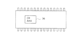
そして、主基板33は、上述した各種制御基板に対し、所定の指令(コマンド)を出力することにより、パチンコ遊技機1の全体の制御を司る。つまり、主基板33は、ソレノイド等の各種アクチュエータ以外にも払出制御基板31、発射制御基板32、表示制御基板34、ランプ音声制御基板35などを制御対象とする。なお、各制御基板31〜35等は、制御を司るCPU、遊技プログラムを記憶したROM、遊技の進行に応じた必要なデータを記憶するRAM、各種機器との連絡をとるポート、各種抽選の際に用いられる乱数発生器、時間計数や同期を図る場合などに使用されるクロックパルス発生回路等を含む制御回路基板を有している。なお、本実施の形態では、各制御基板31〜35(発射制御基板32を除く)に搭載されたROM(ICパッケージ)には、機種名等を付したROMシール36(図8参照)が貼付されている。本実施の形態では、かかるROMシール36により、識別標識が構成されている。
【0057】
前記制御回路基板は、基板ボックスと称される箱状体に収納されている。従って、例えば主基板33の実体は、上記制御回路基板であるが、ここでは便宜上、当該制御回路基板及び基板ボックスを併せて主基板33と称することとしている。
【0058】
次に、これら制御基板31〜35(基板ボックス)の取付位置をはじめとする、パチンコ機1の背面側の構成等について、図2を参照しつつ簡単に説明する。
【0059】
前記内枠3には、遊技盤5の背面側において、樹脂材料で形成され、内枠3に開閉可能に支持された機構盤90が設けられている。機構盤90は、上部機構盤90A及び下部機構盤90Bからなり、それぞれが内枠3の一側にて開閉可能に軸支されている。上部機構盤90Aには、タンク91、タンクレール92、払出ユニット93、ケースレール94、役物カバー95などが取り付けられている。
【0060】
タンク91は、上部機構盤90Aの最上部に取り付けられており、払い出されるべき遊技球を貯留する。タンクレール92は、タンク91の下方に取り付けられ、長尺形状のレール本体が右側方向へ右下がりに延びており、ケースレール94へ遊技球を整列状態で誘導するようになっている。払出ユニット93は、遊技球の払い出しを行うための機構であり、ケースレール94の下方に取り付けられ、賞球と貸球の払い出しを行う機構である。この払出ユニット93へ遊技球を誘導するのが、ケースレール94である。
【0061】
また、役物カバー95は、タンクレール92の下方に取り付けられる四角形状の樹脂製カバーであり、遊技盤5の背面側において可変表示装置や表示制御基板、ランプ音声制御基板等を保護する。同図において、表示制御基板34及びランプ音声制御基板35が図示されていないのは、これら基板34,35が前記役物カバー95で覆われているためである。すなわち、表示制御基板34は、前記可変表示装置の裏面側に取付けられている。また、その周囲を囲むようにして、遊技盤5の背面側には、合成樹脂製の集合盤(図示略)が固定されている。集合盤には、各種中継基板が取着されているとともに、前記普通入賞チャッカー、可変入賞装置、作動チャッカー等に入賞した遊技球を集合案内させるべく遊技球流路が設けられている。本実施の形態では、それ以外にも、集合盤には、前記主基板33及びランプ音声制御基板35等が取付固定されている。
【0062】
さて、次には、上記のように構成されてなるパチンコ機1の製造方法について説明する。
【0063】
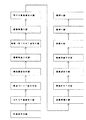
図3は、本実施の形態のパチンコ機1を製造するための主要な工程を説明するための工程図である。当該工程図に従って、パチンコ機1の製造方法について説明すると、まず、内枠3の表側が上を向くようにして寝かせた状態で、当該内枠3を所定の作業位置にセットする。その状態で、当該内枠3に対し、下皿7を取付ける。
【0064】
その後、内枠3の表裏を反転させ、内枠3に対し、スライド錠を取付ける。また、内枠3の裏面側の所定位置に発射ユニット10を取付ける。次に、内枠3の裏面側から遊技盤5を取付け、続いて機構盤90を取付ける。
【0065】
ここで、遊技盤5は、別途の工程を経て予め製造されている。遊技盤5の製法について簡単に説明すると、まず、ベニヤ板の表面に、機種固有のデザインを有してなるセル画を貼付し、所定箇所に穴開け等の切削加工、ルータ加工を施す。その後、ベニヤ板の表側面にプレス加工を施し、釘用の仮穴を開けておき、レールや風車用の溝、穴を形成しておく。次いで、釘を植設し、内外レールをはめ込み、風車を打ち付ける。その後コーナー飾り(装飾部材)、及び、普通入賞チャッカー、可変入賞装置、作動チャッカー、スルーチャッカー等の役物を取付ける。その後、ベニヤ板を反転させ、裏面側に、集合盤、可変表示装置の液晶表示部を取付け、所定の配線接続を行う。次に、かかる遊技盤5を90度起こしてテスト基板を用いて所定の動作テストを行う。そして、テストに合格した場合に、遊技盤5の所定位置に証紙(図示略)を取付けることで、遊技盤5が製造される。
【0066】
さて、遊技盤5及び機構盤90の取付が完了した後、上記各種制御基板31〜35を取付ける。次に、各制御基板31〜35等の配線接続工程を経る。配線接続が完了した後、内枠3を90度起こして、今度は内枠3の表側に前面枠セット4(上皿5を含む)を取付ける。その後、前面枠セット4側の電気部品等との配線接続を行う。
【0067】
続いて、所定の発射テストを行い、発射テストに合格した場合に、内枠3の所定位置に証紙(図示略)を貼付する。その後、かかる内枠3を、予め用意してあった外枠2に対し取付ける。この時点で、パチンコ機1はほぼ完成しているのであるが、引き続いて、本実施の形態特有の認識工程、及び、検査工程を経る。
【0068】
まずは、認識工程について詳述する。本実施の形態では、パチンコ機1は、一連の流れ作業により製造されるのであるが、流れ作業に際して、内枠3等は、図示しないコンベア等で搬送されつつ上述した各工程を経る。当該認識工程に際しても、パチンコ機1は、搬送されながら機種の認識作業が行われるようになっている。
【0069】
認識工程に際しては、図4に示すような認識装置41が採用される。内枠3が外枠2に取付けられたパチンコ機1は、かかる認識装置41に案内され、所定位置に停止された状態で機種の認識が行われた後、次の検査工程へと供される。認識装置41は、鉛直方向に立設された支柱42と、支柱42の中間位置から水平方向に延びるアーム部43とを備えている。アーム部43のほぼ先端には、撮像手段を構成するパターン検出センサ44が設けられている。本実施の形態では、このパターン検出センサ44は固定されており、認識処理中は、当該センサ44とパチンコ機1との相対位置関係が一定とされる。
【0070】
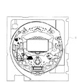
ここで、図5は、機種名が例えば「CR AAA−X1」というパチンコ機1の遊技盤5を示す正面模式図であり、図6は、機種名が例えば「CR BBB−X1」というパチンコ機1の遊技盤5を示す正面模式図である。これらの図に示すように、「CR AAA−X1」というパチンコ機1に関しては、「寿司屋」をモチーフにしたセル画が採用され、寿司職人及び女の子のデザインが表されている。一方、「CR BBB−X1」というパチンコ機1に関しては、「愛犬」をモチーフにしたセル画が採用され、各種犬のデザインが表されている。
【0071】
上述した一定とされた相対位置関係において、パターン検出センサ44の撮像エリア(図中太い枠線で囲んだ領域)は、遊技盤5のセル画の所定位置(図では左部位置)に対向するようになっており、同一機種にあっては、常にほぼ同じデザインパターンが撮像され、機種が相違することで、互いに異なったデザインパターンが撮像されるようになっている。
【0072】
また、図4に示すように、支柱42には、特定手段を構成するチェッカー45が設けられている。チェッカー45は必ずしも支柱42に設けられていなくてもよい。チェッカー45及びパターン検出センサ44は電気的に接続されており、パターン検出センサ44にて撮像された画像データがチェッカー45へと送信されるようになっている。チェッカー45では、送信された画像データに基づき、撮像エリア内でのデザインパターンが読み込まれるとともに、予め登録(記憶)されている機種固有のデザインパターンとの比較処理が行われる。そして、チェッカー45では、その比較結果に基づいて機種名が特定され、当該機種名に関する情報が、後述する検査装置51(図7参照)へと送信されるようになっている。
【0073】
さて、本実施の形態では、説明の便宜上、8種類の機種に関する認識・検査が行われる場合について説明する。機種名としては、「CR AAA−X1」、「CR AAA−X2」、「AAA−Y1」、「AAA−Y2」、「CR BBB−X1」、「CR BBB−X2」、「BBB−Y1」、「BBB−Y2」の8種類である。ここで、冠に「CR」が付されているものは、いわゆる「CR機」であることを示しており、所定の大当たり図柄で大当たり状態が発生した後、次回の大当たりまで確率変動モードが付与されるタイプを表している。また、「CR」が付されていないものは、いわゆる「現金機」であることを示している。さらに、末尾に「X1」が付されているものは、大当たり確率が315分の1であることを表しており、「X2」が付されているものは、大当たり確率が300分の1であることを表している。併せて、末尾に「Y1」が付されているものは、大当たり確率が250分の1であることを表しており、「Y2」が付されているものは、大当たり確率が200分の1であることを表している。勿論、大当たり確率に代えて、又は加えて、大当たり時の賞球数が相違するよう構成してもよい。
【0074】
また、「AAA」が付されているものは、セル画が「寿司屋」をモチーフにされたものであり、液晶表示部においても「寿司屋」をモチーフにした各種表示演出が行われるようになっている。一方、「BBB」が付されているものは、セル画が「愛犬」をモチーフにされたものであり、液晶表示部においても「犬」をモチーフにした各種表示演出が行われるようになっている。ただし、同じ「AAA」であっても、「CR機」か「現金機」かによって、また、大当たり確率の相違によって、セル画のデザインパターンが相違している。「BBB」の場合も同様である。「AAA」同士、「BBB」同士はそれぞれシリーズ機と称される。そして、本実施の形態では、上記認識装置41を経ることによって、認識対象となったパチンコ機1が、上記8種類の機種のうちいずれの機種であるかを特定できるようになっている。
【0075】
上記のように、機種名が特定された後、パチンコ機1は次なる搬送によって、図7に示す検査装置51へと案内され、検査工程に供される。検査装置51は、鉛直方向に立設された支柱52と、支柱52の複数の中間位置から水平方向に延びる前記制御基板31,33,34,35に対応する4本のアーム部53,54,55,56とを備えている。各アーム部53〜56には、カラー画像センサ61,62,63,64が設けられている。本実施の形態では、各アーム53〜56は図示しない移動機構により上下方向に移動可能となっており、カラー画像センサ61〜64は図示しない移動機構により左右方向に移動可能となっている。そして、機種毎に相違する場合がある各制御基板31,33,34,35の位置に対し、カラー画像センサ61〜64の位置が調整できるようになっている。検査中は、当該センサ61〜64と、各制御基板31,33,34,35のROMに貼付されたROMシール36(図8参照)との相対位置関係が一定とされる。
【0076】
また、支柱52には、検査手段65が設けられている。検査手段65は必ずしも支柱52に設けられていなくてもよい。検査手段65及び前記各カラー画像センサ61〜64は電気的に接続されており、カラー画像センサ61〜64にて撮像されたカラー画像データが検査手段65へと送信されるようになっている。検査手段65では、送信されたカラー画像データに基づき、撮像エリア内での各ポジション毎の色彩データが読み込まれるとともに、予め登録(記憶)されている機種固有のポジション毎の色彩データに基づいて、ROMシール36の機種特定が行われる。
【0077】
本実施の形態では、上記した機種毎に、ROMシール36に付された識別情報等に関し色彩上の特徴を持たせることとしている。すなわち、図9に示すように、機種名「CR AAA−X1」のROMシール36に関しては、「CR」の文字が青色に、「AAA」の文字が赤色に、背景色が銀色に設定されている。また、「CR AAA−X2」のROMシール36に関しては「CR」の文字が青色に、「AAA」の文字が緑色に、背景色が銀色に設定されている。「AAA−Y1」のROMシール36に関しては「CR」の文字が付されておらず、「AAA」の文字が青色に、背景色が銀色に設定されている。「AAA−Y2」のROMシール36に関しては「CR」の文字が付されておらず、「AAA」の文字が緑色に、背景色が銀色に設定されている。さらに、「CR BBB−X1」のROMシール36に関しては「CR」の文字が赤色に、「BBB」の文字が銀色に、背景色が青色に設定されている。「CR BBB−X2」のROMシール36に関しては「CR」の文字が赤色に、「BBB」の文字が緑色に、背景色が青色に設定されている。「BBB−Y1」のROMシール36に関しては「CR」の文字が付されておらず、「BBB」の文字が緑色に、背景色が青色に設定されている。「BBB−Y2」のROMシール36に関しては「CR」の文字が付されておらず、「BBB」の文字が赤色に、背景色が青色に設定されている。
【0078】
そして、検査手段65では、上記のように特定されたROMシール36の機種情報と、前記認識装置41のチェッカー45から送信された当該パチンコ機1の機種名情報とが一致するか否かを判定する。4つの制御基板31,33,34,35のROMシール36の機種情報に関し、全て一致した場合には、正しいROMシール36が貼付されているものとして次の袋詰工程(図3参照)へと案内される。一方、1つでも一致しないと判定された場合には、誤ったROMシール36が貼付された(若しくは誤った基板が取付けられた)おそれがあるものとして、当該パチンコ機1を製造ラインから一旦外される。
【0079】
以上詳述したように、本実施の形態によれば、各制御基板31,33,34,35のROMシール36が正しく貼付されているか否かを検査する検査工程の前段階において、当該パチンコ機1が如何なる機種であるかを認識する認識工程を設けることとしている。このため、現在製造されるパチンコ機1が如何なる機種であるのかを確実に認識した上で、検査工程に供されることから、検査工程において、その認識結果に基づいた検査を正確に行うことができる。従って、ROMシール36が誤って貼付されたままパチンコ機1が出荷されてしまうといった事態を防止することができる。
【0080】
また、認識工程に際しては、認識装置41が用いられる。より詳しくは、認識装置41のパターン検出センサ44により、少なくともセル画の特定エリアが撮像され、チェッカー35によって、当該撮像されたエリア内のデザインパターンが認識され、該認識結果と、予め記憶された基礎データとに基づいて機種が特定される。そして、認識された機種に関する情報が検査装置51へと送信され検査装置51での検査に際しそれが用いられる。このように、人手に頼ることなく自動的に認識、検査を行うことができることから、一連の流れ作業の中で効率的な認識作業、検査作業を行うことができ、効率的な製造を行うことができる。
【0081】
しかも、認識に際し撮像される特定エリアは、どのパチンコ機1においても通常遊技盤5に設けられるセル画の一部である。当該セル画は、機種が相違すれば必然的に相違するものである。これは、遊技者が人目で機種(型式等)を把握できるようにすること等のためである。そして、本実施の形態では、そのセル画の一部の特定エリアを認識することでより確実に、かつ、比較的容易に機種を認識することができる。
【0082】
さらに、セル画で認識できることから、特別に認識用の識別手段を別途設けなくてもよいというメリットがある。また、セル画の特定エリアが外部から容易に撮像できる位置に設定されることで、上記認識をより確実に容易に行うことができる。
【0083】
併せて、前記認識工程に際しては、セル画の特定エリアとパターン検出センサ44との相対位置関係が常にほぼ一定とされる。このため、上記チェッカー45による特定に際し、そのたびに、デザインパターンの認識結果と予め記憶された基礎データとのすり合わせに支障が生じるとしった煩わしさを払拭でき、安定した認識作業を正確に繰り返し行うことができる。特に、パターン検出センサ44が固定されているので、上記相対位置関係を一定としやすい。また、パターン検出センサ44に関し、別途の移動機構を設けなくて済む。
【0084】
また、「AAA」同士、「BBB」同士はいったシリーズ機間で、誤って各制御基板31,33,34,35が取付けられた場合、もしも大当たり発生確率や大当たり時の賞球数がシリーズ機間で異なる場合、遊技者や遊技場関係者にとって不足の不利益が及んでしまうことが懸念される。この点、本実施の形態では、そのような事態を未然に防止することができる。
【0085】
なお、実施の形態に何等限定されるものではなく、主旨を逸脱しない範囲において種々なる形態で実施し得るものである。例えば次のように実施してもよい。
【0086】
(a)上記実施の形態では、検査工程の直前段階において、認識工程を経ることとしている。これに対し、他の工程の前段階に認識工程を設けることとしても各種効果が奏される。
【0087】
(b)例えば、機種固有の部品、部材又は装置を取付ける取付工程の前段階に認識工程を経ることとしてもよい。部品、部材、装置としては、例えば、可変表示装置、普通入賞チャッカー、可変入賞装置、作動チャッカー、スルーチャッカー等の外、ランプや風車等の各種部材等が挙げられる。この場合、取付工程において、機種固有の部品、部材又は装置を取付ける場合において、取付対象を誤ったりするおそれを低減できる。
【0088】
(c)また例えば、機種固有の制御手段(各種制御基板31〜35等)を取付ける取付工程の前段階に認識工程を経ることとしてもよい。この場合、取付工程において、機種固有の制御手段を取付ける場合において、別の機種用の制御手段を誤って取付けてしまうといったおそれを低減できる。
【0089】
(d)さらに、機種固有のROMシール36等の制御手段確認用の識別標識を取付ける取付工程の前段階に認識工程を経ることとしてもよい。この場合、取付工程において、機種固有のROMシール36等を貼付する場合において、別機種用のROMシール36を誤って貼付してしまうといったおそれを低減できる。また、ROMシール36に限られず、例えば基板ボックスに貼付される識別シールや、CPUや制御基板自身に識別シールを貼付する場合にも適用できる。
【0090】
(e)また、取付けられた機種固有の部品、部材又は装置が正しいか否かを判定するための検査工程を設け、当該検査工程の前段階に認識工程を経ることとしてもよい。この場合、次なる検査工程において、機種固有の部品、部材又は装置が正しく取付けられているか否かを正確に検査することができ、ひいては誤って取付けられたまま出荷されてしまうといった事態を抑制できる。
【0091】
(f)さらに、取付けられた機種固有の制御手段(制御基板31〜35等)が正しいか否かを判定するための検査工程を設け、当該検査工程の前段階に認識工程を経ることとしてもよい。この場合、次なる検査工程において、機種固有の制御手段が正しく取付けられているか否かを正確に検査することができ、ひいては誤って取付けられたまま出荷されてしまうといった事態を抑制できる。
【0092】
(g)併せて、機種固有の所定の加工を施す加工工程の前段階に認識工程を経ることとしてもよい。この場合、次なる加工工程において、機種固有の所定の加工が適正に施される。従って、誤って別の機種用の加工を施してしまうといった事態を抑制できる。なお、加工工程としては、例えば、切削加工工程、釘等を植設する植設加工工程等が挙げられる。
【0093】
(h)上記実施の形態とは異なるタイプのパチンコ機等の製造方法にも適用できる。例えば、大当たり図柄が表示された後に所定の領域に遊技球を入賞させることを必要条件として特別遊技状態となるパチンコ機の製造にも具体化できる。また、可変表示装置のないパチンコ機(例えば大羽根やクルーンといった役物が搭載されているタイプや、いわゆる多くのチューリップが搭載されているタイプ等)にも応用できる。また、パチンコ機以外にも、アレパチ、雀球、スロットマシン、パチンコ機とスロットマシンとが融合した遊技機等の各種遊技機として実施することも可能である。なお、スロットマシンは、例えばコインを投入して図柄有効ラインを決定させた状態で操作レバーを操作することにより図柄が変動され、ストップボタンを操作することにより図柄が停止されて確定される周知のものである。この場合、遊技媒体はコイン、メダル等が代表例として挙げられる。
【0094】
また、パチンコ機とスロットマシンとが融合した遊技機の具体例としては、複数の図柄からなる図柄列を変動表示した後に図柄を確定表示する可変表示手段を備えており、遊技球打出用のハンドルを備えていないものが挙げられる。この場合、所定の操作(ボタン操作)に基づく、所定量の遊技球の投入の後、例えば操作レバーの操作に起因して図柄の変動が開始され、例えばストップボタンの操作に起因して或いは所定時間経過することにより図柄の変動が停止され、その停止時の確定図柄がいわゆる大当たり図柄であることを必要条件として遊技者に有利な大当たり状態が発生させられ、遊技者には、下部の受皿に多量の遊技球が払い出されるものである。
【0095】
(i)なお、スロットマシンや、パチンコ機とスロットマシンとが融合した遊技機に関しては、上記実施の形態で具体化したセル画に代えて、フロントパネルに付されるパネル画についてデザインパターンを認識することに基づいて、機種を認識できる。当該パネル画についても、機種が相違すれば必然的に相違するものであることから、特に認識用の識別手段を別途設けなくてもよいという上記実施の形態と同様の作用効果が奏される。
【0096】
(j)パチンコ機1の製造は、上記工程図のような順序等に拘泥されるものではない。従って、多少の順序の相違や、所定の工程の省略、別途の工程を設けることは、通常のパチンコ機の製造の範疇から逸脱するものでない限り、何ら支障はない。
【0097】
(j)上記実施の形態ではパターン検出センサ44及びチェッカー45により、少なくともセル画の特定エリアが撮像され、当該撮像されたエリア内のデザインパターンが認識されるようになっているが、セル画の色彩パターンが機種毎に相違するような場合には、パターン検出センサ44の代わりにカラー画像センサを用いることとしてもよい。
【0098】
(k)上記実施の形態における認識工程と検査工程とを一度に(同じ位置で)行うこととしてもよい。
【図面の簡単な説明】
【図1】一実施の形態におけるパチンコ機を示す正面図である。
【図2】パチンコ機を示す背面図である。
【図3】パチンコ機の製造工程を示す工程図である。
【図4】認識装置等を示す模式図である。
【図5】あるパチンコ機の遊技盤を示す正面模式図である。
【図6】別のパチンコ機の遊技盤を示す正面模式図である。
【図7】検査装置等を示す模式図である。
【図8】ROMに貼付されたROMシールを模式的に示す正面図である。
【図9】機種名に対応するROMシールの文字等の色彩の関係を説明する図表である。
【符号の説明】
1…遊技機としてのパチンコ機、2…外枠、3…内枠、4…前面枠セット、5…遊技盤、31…制御手段としての払出制御基板、32…制御手段としての発射制御基板、33…制御手段としての主基板、34…制御手段としての表示制御基板、35…制御手段としてのランプ音声制御手段、41…認識装置、44…撮像手段としてのパターン検出センサ、45…特定手段としてのチェッカー、51…検査装置、61〜64…カラー画像センサ、65…検査手段。[0001]
TECHNICAL FIELD OF THE INVENTION
The present invention relates to a gaming machine such as a pachinko machine, and more particularly to a method for manufacturing a gaming machine.
[0002]
[Prior art]
BACKGROUND ART Conventionally, it is known that a game machine such as a pachinko machine goes through a number of steps. For example, in a pachinko machine, a control board box for performing various controls is mounted, a game board is mounted on an inner frame, or various members, devices, and the like are mounted. Reference 1). In addition to the mounting, a step of cutting or implanting a nail is also required.
[0003]
[Patent Document 1]
JP 2001-170268 A
[0004]
[Problems to be solved by the invention]
By the way, various control boards to be mounted, various devices, and the like (objects to be mounted) are specific to the type (model) of the gaming machine to be manufactured. In other words, different models have different mounting targets to be mounted. Also, various processing methods may be different depending on the model. For this reason, in the manufacturing process, there is a possibility that the mounting target may be erroneously mounted on another model, or a process for a model different from the model to be manufactured may be performed. In particular, in the case where similar game machines called sibling models are manufactured, the above-described error is likely to occur.
[0005]
In addition, the above-mentioned inconvenience is inherent in the manufacture of not only pachinko machines but also game machines such as slot machines.
[0006]
SUMMARY OF THE INVENTION The present invention has been made to solve the above-described problems, and has as its main object to provide a method of manufacturing a gaming machine and the like that can minimize errors in manufacturing.
[0007]
Means for Solving the Problems and Effects of the Invention
Means effective for achieving the above object are shown below. The operation and the like will be described as needed.
[0008]
Means 1. A method for manufacturing a gaming machine comprising at least a model-specific front side design unit,
A method for manufacturing a gaming machine, comprising a step of recognizing a model based on recognizing a specific area of the design section in a step before a final step.
[0009]
According to the means 1, when manufacturing a gaming machine having at least a front-side design unit unique to a model, a recognition process is performed in a process preceding the final process. For this reason, after being surely recognizing what kind of game machine the currently manufactured gaming machine is, it is provided to the next process, and in the subsequent processes, it is possible to perform an operation based on the recognition result. it can. Therefore, errors in manufacturing can be prevented. In the recognition step, the model is recognized based on the recognition of the specific area of the front-side design section unique to the model. Here, the front-side design unit is inevitably likely to be different if the model is different, and it is possible to recognize the model more reliably and relatively easily by recognizing a part of the specific area. it can.
[0010]
Note that “model” can be replaced with, for example, wording such as model, type, type, etc. In short, the category of a model in which display effects, character shapes, etc. are completely different are different. Of course, even if the display effect is the same, the so-called jackpot probability is different, and the player benefits (for example, the number of prize balls) at the time of the jackpot are different. Included in the category.
[0011]
Means 2. A method for manufacturing a gaming machine comprising at least a model-specific front side design unit,
A recognition step of recognizing a model based on recognizing a specific region of the design unit by the recognition device, and providing a predetermined process based on a recognition result in the recognition step. A game machine manufacturing method.
[0012]
According to the means 2, when manufacturing a game machine having at least a model-specific front-side design portion, a recognition process using a recognition device is performed. For this reason, what kind of game machine is currently manufactured is reliably recognized by the recognition device, and is provided to the next process. Appropriate work can be performed. Therefore, errors in manufacturing can be prevented. In the recognition step, the model is recognized based on the recognition device recognizing the specific area of the front-side design unit unique to the model. Here, the front-side design unit is inevitably likely to be different if the model is different, and it is possible to recognize the model more reliably and relatively easily by recognizing a part of the specific area. it can.
[0013]
Means 3. 3. The method for manufacturing a gaming machine according to claim 2, wherein the predetermined step is a mounting step of mounting a model-specific part, member or device.
[0014]
According to the means 3, in the recognition step, the type of the gaming machine can be accurately recognized in the recognition step. Can be reduced.
[0015]
Means 4. 4. The method of manufacturing a gaming machine according to claim 2, wherein the predetermined step is a mounting step of attaching a control unit specific to the model.
[0016]
According to the means 4, since the type of the gaming machine can be accurately recognized in the recognition step, another control means can be used even in the case of attaching the model-specific control means in the next mounting step. It is possible to reduce the risk of being attached by mistake.
[0017]
Means 5. The method for manufacturing a gaming machine according to any one of means 2 to 4, wherein the predetermined step is an attaching step of attaching an identification mark for confirming control means unique to the model.
[0018]
According to the means 5, in the recognition step, the type of the gaming machine can be accurately recognized in the recognition step. Therefore, even in the case of attaching the identification mark for the control means confirmation unique to the model in the next mounting step, It is possible to reduce a possibility that another identification mark is erroneously attached. Examples of the identification mark include a ROM sticker attached to a ROM chip on a board, an identification sticker attached to a board box, and the like. Further, as described above, the “model-specific control means” controls the so-called jackpot probability to be different between the models, and the profit (for example, the number of prize balls) for the player at the time of the jackpot differs as described above. The purpose is to include those that perform such control.
[0019]
Means 6. 6. The game machine according to claim 2, wherein the predetermined step is an inspection step for determining whether or not a part, a member, or a device specific to the attached model is correct. Method.
[0020]
According to the means 6, in the recognition step, the type of the gaming machine can be accurately recognized in the recognition step. Therefore, in the next inspection step, it is determined whether the model-specific parts, members, or devices are correctly attached. Can be inspected accurately, and a situation in which the product is shipped with it attached incorrectly can be suppressed.
[0021]
Means 7. 7. The method for manufacturing a gaming machine according to claim 2, wherein the predetermined step is an inspection step for determining whether or not the attached control means specific to the model is correct.
[0022]
According to the means 7, in the recognition step, the type of the gaming machine can be accurately recognized in the recognition step. Therefore, in the next inspection step, it is accurately determined whether or not the model-specific control means is correctly attached. Inspection can be performed, and a situation in which the product is shipped while being erroneously attached can be suppressed.
[0023]
Means 8. The predetermined step is an inspection step attached to a model-specific control means, and is a test step for determining whether or not the identification mark for confirmation of the control means is correct. 3. The method for manufacturing a gaming machine according to claim 1.
[0024]
According to the means 8, in the recognition step, the type of the gaming machine can be accurately recognized in the recognition step. Therefore, in the next inspection step, the identification mark for confirming the control means specific to the model is correctly attached. It is possible to accurately check whether or not the product is mounted, and thus it is possible to suppress a situation in which the product is shipped while being erroneously attached. Examples of the identification mark include a ROM sticker attached to a ROM chip on a board, an identification sticker attached to a board box, and the like.
[0025]
Means 9. The method for manufacturing a gaming machine according to any one of means 2 to 8, wherein the predetermined step is a processing step of performing a predetermined processing specific to a model.
[0026]
According to the means 9, in the recognition step, the type of the gaming machine can be accurately recognized in the recognition step, so that in the next processing step, predetermined processing specific to the model is appropriately performed. Therefore, it is possible to suppress a situation in which processing for another model is performed by mistake. Examples of the processing step include a cutting step and a planting step of planting nails and the like.
[0027]
Means 10. The method for manufacturing a gaming machine according to any one of means 1 to 9, wherein the design of the design section is necessarily different based on a model difference.
[0028]
If the design of the front side design part is necessarily different based on the difference of the model as in the means 10, the model can be recognized more accurately. In addition, since it is not necessary to separately provide an identification means for recognition, no special trouble is required for recognition. As a result, the number of manufacturing steps and the manufacturing cost can be reduced.
[0029]
Means 11. The method for manufacturing a gaming machine according to any one of means 1 to 10, wherein the design unit is a cell image provided on a game board constituting a gaming area.
[0030]
According to the means 11, the model is recognized based on the recognition of the specific area of the cell image provided on the game board constituting the game area. Since the cell images are inevitably different depending on the model, the operation and effect that the identification means for recognition does not need to be separately provided is exhibited. In addition, since the specific area of the cell image is set at a position where visual recognition, imaging, and the like are easily performed from the outside, the recognition operation can be performed relatively easily.
[0031]
Means 12. The method for manufacturing a gaming machine according to any one of means 1 to 10, wherein the design portion is a panel image attached to a front panel.
[0032]
According to the means 12, the model is recognized based on the recognition of the specific area of the panel image attached to the front panel. Since the panel images are inevitably different for different models, there is an operational effect that it is not particularly necessary to separately provide an identification means for recognition. In addition, since the specific region of the panel image is set at a position where visual recognition, imaging, and the like are easily performed from the outside, the recognition operation can be performed relatively easily.
[0033]
Means 13. In the recognition step, a recognition device is used, and the recognition device includes:
Imaging means for imaging at least the specific area;
Identifying means for recognizing a design pattern in an image field of view imaged by the imaging means, and identifying a model based on the recognition result and basic data stored in advance;
13. The method for manufacturing a gaming machine according to any one of means 1 to 12, further comprising:
[0034]
According to the means 13, a recognition device is used in the recognition step. At least a specific area of the front-side design section is imaged by the imaging means of the recognition device. The specifying means of the recognition device recognizes the design pattern in the visual field of the image picked up by the image pickup means, and specifies the model based on the recognition result and the basic data stored in advance. As described above, since it can be automatically recognized without relying on humans, efficient manufacturing can be performed in a series of continuous operations.
[0035]
Means 14. 14. The method of manufacturing a gaming machine according to claim 13, wherein in the recognition step, a relative positional relationship between the specific area and the imaging unit is always substantially constant.
[0036]
According to the means 14, in the recognition step, the relative positional relationship between the specific area and the imaging means is always substantially constant. For this reason, it is possible to avoid a situation in which the matching of the design pattern recognition result with the pre-stored basic data is hindered each time the identification is performed by the identification means, and it is possible to accurately and repeatedly perform a stable recognition operation. it can.
[0037]
Means 15. 15. The method of manufacturing a gaming machine according to claim 13, wherein at least the imaging unit is fixed at a fixed position.
[0038]
According to the means 15, since at least the image pickup means is fixed at the fixed position, it is easy to make the relative positional relationship with the specific area constant. Further, it is not necessary to provide a separate moving mechanism for the image pickup means.
[0039]
Means 16. 15. The method of manufacturing a gaming machine according to claim 13 or 14, wherein at least the imaging unit is configured to be movable.
[0040]
According to the means 16, since at least the imaging means is movable, it is possible to sufficiently cope with a change in the size of the gaming machine.
[0041]
Means 17. The method for manufacturing a gaming machine according to any one of means 1 to 16, wherein the gaming machine is a pachinko gaming machine (pachinko machine). Above all, as a basic configuration of a pachinko gaming machine, an operating port provided with an operation handle and firing a game ball to a predetermined game area in accordance with the operation of the handle, the game ball is arranged at a predetermined position in the game area. Is configured to be given a predetermined value when winning. Particularly, the game area is mainly constituted by a game board, and a cell image having a model-specific design is attached to the front of the game board.
[0042]
Means 18. The method for manufacturing a gaming machine according to any one of means 1 to 16, wherein the gaming machine is a spinning-type gaming machine (slot machine). Here, as a configuration of the spinning-type gaming machine, "the identification information sequence (specifically, a reel, and the identification information is a symbol attached to the reel) composed of a plurality of identification information is variably displayed (specifically, Is provided with variable display means for confirming and displaying the identification information after the rotation of the reel), the change of the identification information is started by the operation of the starting operation means (for example, operation lever), and the stopping operation means The fluctuation of the identification information is stopped by the operation of the stop button (for example, a stop button) or after a predetermined time has elapsed, and a special condition advantageous to the player is required on condition that the fixed identification information at the time of the stop is the specific identification information. It is a spinning-type gaming machine provided with a special game state generating means for generating a game state. In particular, a front panel is provided below the identification information, and a panel image having a model-specific design is attached to the front panel.
[0043]
Means 19. 17. The method for manufacturing a gaming machine according to any one of means 1 to 16, wherein the gaming machine is a gaming machine obtained by fusing a pachinko machine and a slot machine. Above all, the basic configuration of the integrated gaming machine is as follows: “The identification information sequence including a plurality of identification information (specifically, a reel, and the identification information is a symbol attached to the reel) is variably displayed (specifically, Variable information means for confirming and displaying the identification information after the rotation of the reel), the change of the identification information is started due to the operation of the starting operation means (for example, the operation lever), and the stop operation is performed. Fluctuation of the identification information is stopped due to the operation of the means (for example, the stop button) or after a predetermined time elapses, and it is advantageous to the player on the condition that the fixed identification information at the time of the stop is the specific identification information. Special game state generating means for generating a special game state, a game ball is used as a game medium, and a predetermined number of game balls are required at the start of the change of the identification information. Becomes gaming machine "in which a is configured such that a number of game balls are paid out upon the state of generation. In particular, a front panel is provided below the identification information, and a panel image having a model-specific design is attached to the front panel.
[0044]
Means 20. A gaming machine manufactured by the manufacturing method according to any one of means 1 to 19.
[0045]
BEST MODE FOR CARRYING OUT THE INVENTION
Hereinafter, an embodiment in which a method of manufacturing a gaming machine is embodied in a method of manufacturing a pachinko gaming machine (hereinafter, simply referred to as “pachinko machine”) will be described in detail with reference to the drawings.
[0046]
First, a schematic configuration of the pachinko machine will be described. As shown in FIG. 1, the pachinko machine 1 includes an outer frame 2 and an inner frame 3 provided at a front portion of the outer frame 2 and supported by one side of the outer frame 2 so as to be openable and closable. .
[0047]
On the front side of the inner frame 3, a front frame set 4 is provided so as to be freely opened and closed. The front frame set 4 is always locked to the inner frame 3 by a slide lock (not shown). The inner frame 3 is always locked to the outer frame 2 by a slide lock. On the rear side of the inner frame 3 (in the back of the front frame set 4 and inside the outer frame 2), a game board 5 is detachably mounted.
[0048]
An upper plate 6 for storing game balls is provided below the front frame set 4. A lower plate 7 is provided substantially at the center of the lower portion of the front surface of the inner frame 3. At the side of the lower plate 7, a game ball firing handle 8 is provided. The handle 8 is connected to a firing unit 10 (see FIG. 2), and a game ball is fired from the firing unit 10 when the player rotates the handle 8.
[0049]
A plurality of openings are formed in the game board 5 by being subjected to router processing, and corresponding to each of the openings, a normal winning chucker, a variable winning device, an operating chucker, a variable display device, a through chucker, and the like. (None of them are shown in FIG. 1). The variable display device includes a liquid crystal display unit and a center frame provided so as to surround the liquid crystal display unit. On the liquid crystal display unit, for example, three display columns of a left symbol column, a middle symbol column, and a right symbol column are displayed. Each symbol row is composed of a plurality of symbols as identification information, and these symbols are variably displayed so as to scroll for each symbol row.
[0050]
More specifically, the symbol on the liquid crystal display unit of the variable display device is variably displayed based on a game ball entering an operation chucker provided below the variable display device. Then, when the combination of stopped symbols becomes a specific combination set in advance, a special game value is given. That is, a big hit state occurs, the big winning opening of the variable winning device becomes a predetermined open state (specifically, opens for a predetermined time and a predetermined number of times), and a game ball is in a state where it is easy to win. Note that the variable winning device is normally in a state where the game ball cannot be won or is hardly won.
[0051]
Also, as is well known, a predetermined number of prize balls (game balls) are paid out to the upper plate 6 or the lower plate 7 based on the game balls entering the ordinary prize chucker, the variable prize device, and the operation chucker. . In addition, a large number of nails are planted on the game board 5 for appropriately dispersing and adjusting the flowing direction of the game balls, and various members (accessories) such as lamps and windmills are provided. .
[0052]
The pachinko machine 1 configured as described above includes a plurality of control means on the back side of the game board 5 for controlling various control targets. More specifically, as shown in FIG. 2, the pachinko machine 1 includes, as main control means, a payout control board 31, a launch control board 32, a main board 33, a display control board 34 (see FIG. 7), and a lamp sound. A control board 35 (see FIG. 7) is provided. The payout control board 31 controls the payout unit 93 and controls a predetermined number of premium balls (game balls) for the upper plate 6 or the lower plate 7 based on the game balls entering the normal prize chucker, the variable prize device, and the operating chucker. ) And the payout of a ball rental (game ball).
[0053]
The launch control board 32 controls the launch unit 10 described above, and controls launch of a game ball based on a rotating operation of the handle 8 for launching a game ball.
[0054]
The display control board 34 controls the liquid crystal display unit described above, and when a game ball enters the operating chucker provided below the variable display device, the symbol of the liquid crystal display unit is displayed in each symbol row. Scroll display every time. In addition, an effect display or the like when a so-called reach state or a big hit state occurs is also performed.
[0055]
The lamp sound control board 35 controls various lamps and the like attached to the game board 5 and the like, and turns on / off / blinks these lamps in accordance with a game state. In addition, the sound output mechanism is set as a control target, and output control of sound effects and sounds accompanying the game is performed. Note that the voice control board and the lamp control board may be configured separately.
[0056]
The main board 33 controls the entire pachinko gaming machine 1 by outputting a predetermined command to the various control boards described above. That is, the main board 33 controls the payout control board 31, the emission control board 32, the display control board 34, the lamp sound control board 35, and the like in addition to various actuators such as solenoids. Each of the control boards 31 to 35 and the like includes a CPU for controlling, a ROM for storing a game program, a RAM for storing necessary data according to the progress of the game, a port for communicating with various devices, and various kinds of lottery. And a control circuit board including a clock pulse generating circuit used for time counting and synchronization, and the like. In the present embodiment, a ROM sticker 36 (see FIG. 8) with a model name is attached to a ROM (IC package) mounted on each of the control boards 31 to 35 (excluding the firing control board 32). Have been. In the present embodiment, the identification mark is constituted by the ROM seal 36.
[0057]
The control circuit board is housed in a box-shaped body called a board box. Therefore, for example, the substance of the main board 33 is the above-described control circuit board, but here, for convenience, the control circuit board and the board box are collectively referred to as the main board 33.
[0058]
Next, the configuration of the back side of the pachinko machine 1 including the mounting positions of the control boards 31 to 35 (board boards) will be briefly described with reference to FIG.
[0059]
On the inner frame 3, on the back side of the game board 5, there is provided a mechanism board 90 formed of a resin material and supported by the inner frame 3 so as to be openable and closable. The mechanism panel 90 includes an upper mechanism panel 90A and a lower mechanism panel 90B, each of which is pivotally supported on one side of the inner frame 3 so as to be openable and closable. A tank 91, a tank rail 92, a dispensing unit 93, a case rail 94, an accessory cover 95, and the like are attached to the upper mechanism panel 90A.
[0060]
The tank 91 is attached to the uppermost part of the upper mechanism panel 90A, and stores game balls to be paid out. The tank rail 92 is attached below the tank 91, and a long rail body extends rightward and downward to the right to guide the game balls to the case rail 94 in an aligned state. The payout unit 93 is a mechanism for paying out game balls, and is a mechanism that is attached below the case rail 94 and pays out award balls and lending balls. The case rail 94 guides the game ball to the payout unit 93.
[0061]
The accessory cover 95 is a rectangular resin cover attached below the tank rail 92 and protects a variable display device, a display control board, a lamp sound control board, and the like on the back side of the game board 5. In the drawing, the display control board 34 and the lamp sound control board 35 are not shown because these boards 34 and 35 are covered with the accessory cover 95. That is, the display control board 34 is mounted on the back side of the variable display device. On the back side of the game board 5, a collective board (not shown) made of synthetic resin is fixed so as to surround the periphery thereof. Various relay boards are attached to the collecting board, and a game ball flow path is provided to collectively guide the game balls that have won the above-mentioned ordinary winning chuckers, variable winning devices, operating chuckers, and the like. In the present embodiment, in addition, the main board 33, the lamp sound control board 35, and the like are attached and fixed to the collective board.
[0062]
Next, a method of manufacturing the pachinko machine 1 configured as described above will be described.
[0063]
FIG. 3 is a process diagram for explaining main processes for manufacturing the pachinko machine 1 of the present embodiment. The method of manufacturing the pachinko machine 1 will be described with reference to the process chart. First, the inner frame 3 is set to a predetermined work position while being laid down with the front side of the inner frame 3 facing upward. In this state, the lower plate 7 is attached to the inner frame 3.
[0064]
After that, the inner frame 3 is turned upside down, and the slide lock is attached to the inner frame 3. Further, the firing unit 10 is mounted at a predetermined position on the back surface side of the inner frame 3. Next, the game board 5 is attached from the back side of the inner frame 3, and then the mechanism board 90 is attached.
[0065]
Here, the game board 5 is manufactured in advance through a separate process. The manufacturing method of the game board 5 will be briefly described. First, a cell image having a model-specific design is attached to the surface of a plywood, and a predetermined portion is subjected to a cutting process such as drilling and a router process. After that, the front surface of the plywood is subjected to press working to form temporary holes for nails, and grooves and holes for rails and windmills are formed. Next, nails are planted, inner and outer rails are fitted, and a windmill is driven. Thereafter, corner decorations (decorative members) and other accessories such as a normal winning chucker, a variable winning device, an operating chucker, and a through chucker are attached. After that, the plywood is turned over, and the collecting panel and the liquid crystal display section of the variable display device are mounted on the back side, and predetermined wiring connections are made. Next, the game board 5 is raised 90 degrees, and a predetermined operation test is performed using a test board. When the test passes, the game board 5 is manufactured by attaching a certificate stamp (not shown) at a predetermined position of the game board 5.
[0066]
Now, after the mounting of the game board 5 and the mechanism board 90 is completed, the various control boards 31 to 35 are mounted. Next, a wiring connection process for the control boards 31 to 35 and the like is performed. After the wiring connection is completed, the inner frame 3 is raised by 90 degrees, and the front frame set 4 (including the upper plate 5) is attached to the front side of the inner frame 3 this time. Thereafter, wiring connection with the electric components and the like on the front frame set 4 side is performed.
[0067]
Subsequently, a predetermined firing test is performed, and when the firing test is passed, a stamp (not shown) is attached to a predetermined position of the inner frame 3. Thereafter, the inner frame 3 is attached to the outer frame 2 prepared in advance. At this point, the pachinko machine 1 is almost completed, but subsequently goes through a recognition process and an inspection process unique to the present embodiment.
[0068]
First, the recognition step will be described in detail. In the present embodiment, the pachinko machine 1 is manufactured by a series of assembly work. During the assembly work, the inner frame 3 and the like go through the above-described steps while being conveyed by a not-shown conveyor or the like. Also in the recognition process, the pachinko machine 1 performs the recognition operation of the model while being transported.
[0069]
In the recognition step, a recognition device 41 as shown in FIG. 4 is employed. The pachinko machine 1 in which the inner frame 3 is mounted on the outer frame 2 is guided by the recognition device 41, and after the model is recognized while being stopped at a predetermined position, the pachinko machine 1 is provided to the next inspection process. . The recognizing device 41 includes a column 42 erected in the vertical direction, and an arm 43 extending horizontally from an intermediate position of the column 42. At a substantially end of the arm 43, a pattern detection sensor 44 constituting an imaging unit is provided. In the present embodiment, the pattern detection sensor 44 is fixed, and the relative positional relationship between the sensor 44 and the pachinko machine 1 is kept constant during the recognition processing.
[0070]
Here, FIG. 5 is a schematic front view showing the game board 5 of the pachinko machine 1 whose model name is, for example, “CR AAA-X1”, and FIG. 6 is a pachinko machine whose model name is, for example, “CR BBB-X1”. 1 is a schematic front view showing one game board 5; FIG. As shown in these figures, with respect to the pachinko machine 1 called “CR AAA-X1”, a cell image with a motif of “sushi shop” is adopted, and the designs of a sushi chef and a girl are represented. On the other hand, as for the pachinko machine 1 called “CR BBB-X1,” a cell image with a motif of “love dog” is adopted, and various dog designs are shown.
[0071]
In the above-described fixed relative positional relationship, the imaging area of the pattern detection sensor 44 (the area surrounded by the thick frame line in the figure) faces a predetermined position (the left position in the figure) of the cell image of the game board 5. Thus, in the case of the same model, almost the same design pattern is always imaged, and because the model is different, different design patterns are imaged.
[0072]
Further, as shown in FIG. 4, the column 42 is provided with a checker 45 constituting a specifying unit. The checker 45 does not necessarily have to be provided on the column 42. The checker 45 and the pattern detection sensor 44 are electrically connected, and image data captured by the pattern detection sensor 44 is transmitted to the checker 45. The checker 45 reads a design pattern in the imaging area based on the transmitted image data, and performs a comparison process with a model-specific design pattern registered (stored) in advance. Then, in the checker 45, the model name is specified based on the comparison result, and information on the model name is transmitted to the inspection device 51 (see FIG. 7) described later.
[0073]
By the way, in the present embodiment, a case where recognition and inspection regarding eight types of models are performed will be described for convenience of description. As model names, “CR AAA-X1”, “CR AAA-X2”, “AAA-Y1”, “AAA-Y2”, “CR BBB-X1”, “CR BBB-X2”, “BBB-Y1” , “BBB-Y2”. Here, the crown with "CR" indicates that it is a so-called "CR machine", and after a jackpot state occurs with a predetermined jackpot symbol, a probability variation mode is provided until the next jackpot. Represents the type to be performed. Those without “CR” indicate so-called “cash machines”. Furthermore, the one suffixed with “X1” indicates that the jackpot probability is 1/315, and the one suffixed with “X2” has the jackpot probability of 1/300. It represents that. In addition, those suffixed with "Y1" indicate that the jackpot probability is 1/250, and those suffixed with "Y2" indicate that the jackpot probability is 1/200. It represents something. Of course, instead of or in addition to the jackpot probability, the number of prize balls at the time of the jackpot may be different.
[0074]
In the case of "AAA", the cell image has a sushi restaurant as a motif, and various display effects with the "sushi restaurant" as a motif are performed on the liquid crystal display. Has become. On the other hand, the ones with “BBB” are those in which the cel is a motif of “love dog”, and various display effects with the motif of “dog” are also performed on the liquid crystal display unit. I have. However, even for the same “AAA”, the design pattern of the cell image is different depending on whether it is a “CR machine” or a “cash machine”, and also due to a difference in jackpot probability. The same applies to the case of “BBB”. "AAA" and "BBB" are called series machines, respectively. In the present embodiment, through the recognition device 41, the pachinko machine 1 to be recognized can be identified as one of the eight types of models.
[0075]
After the model name is specified as described above, the pachinko machine 1 is guided to the inspection device 51 shown in FIG. 7 by the next conveyance, and is subjected to the inspection process. The inspection device 51 includes a column 52 erected in the vertical direction and four arm portions 53, 54, 54 corresponding to the control boards 31, 33, 34, 35 extending in a horizontal direction from a plurality of intermediate positions of the column 52. 55 and 56. Each of the arms 53 to 56 is provided with a color image sensor 61, 62, 63, 64. In the present embodiment, each of the arms 53 to 56 is vertically movable by a moving mechanism (not shown), and the color image sensors 61 to 64 are horizontally movable by a moving mechanism (not shown). The positions of the color image sensors 61 to 64 can be adjusted with respect to the positions of the control boards 31, 33, 34, and 35, which may be different for each model. During the inspection, the relative positional relationship between the sensors 61 to 64 and the ROM seal 36 (see FIG. 8) attached to the ROM of each of the control boards 31, 33, 34, 35 is kept constant.
[0076]
The column 52 is provided with an inspection unit 65. The inspection means 65 does not necessarily have to be provided on the column 52. The inspection means 65 and the color image sensors 61 to 64 are electrically connected, and the color image data captured by the color image sensors 61 to 64 is transmitted to the inspection means 65. Inspection means 65 reads color data for each position in the imaging area based on the transmitted color image data, and based on color data for each model-specific position registered (stored) in advance. The model of the ROM sticker 36 is specified.
[0077]
In the present embodiment, for each of the above-described models, a color feature is provided for the identification information and the like attached to the ROM sticker 36. That is, as shown in FIG. 9, with regard to the ROM sticker 36 of the model name "CR AAA-X1", the character "CR" is set to blue, the character "AAA" is set to red, and the background color is set to silver. I have. As for the ROM sticker 36 of "CR AAA-X2", the character "CR" is set to blue, the character "AAA" is set to green, and the background color is set to silver. The character “CR” is not attached to the ROM sticker 36 of “AAA-Y1”, the character “AAA” is set to blue, and the background color is set to silver. The character “CR” is not attached to the ROM seal 36 of “AAA-Y2”, the character “AAA” is set to green, and the background color is set to silver. Further, regarding the ROM sticker 36 of “CR BBB-X1”, the character of “CR” is set to red, the character of “BBB” is set to silver, and the background color is set to blue. Regarding the ROM sticker 36 of “CR BBB-X2”, the character “CR” is set to red, the character “BBB” is set to green, and the background color is set to blue. The character “CR” is not attached to the ROM sticker 36 of “BBB-Y1”, the character “BBB” is set to green, and the background color is set to blue. The character “CR” is not attached to the ROM sticker 36 of “BBB-Y2”, and the character “BBB” is set to red and the background color is set to blue.
[0078]
Then, the inspection means 65 determines whether or not the model information of the ROM sticker 36 specified as described above matches the model name information of the pachinko machine 1 transmitted from the checker 45 of the recognition device 41. I do. If all of the model information of the ROM stickers 36 of the four control boards 31, 33, 34, and 35 match, it is determined that the correct ROM sticker 36 is attached to the next bagging step (see FIG. 3). You will be guided. On the other hand, if it is determined that at least one of them does not match, it is determined that there is a possibility that the wrong ROM sticker 36 has been attached (or the wrong board has been attached), and the pachinko machine 1 is temporarily removed from the production line. Is done.
[0079]
As described above in detail, according to the present embodiment, the pachinko machine is provided at a stage prior to the inspection process for inspecting whether the ROM seal 36 of each of the control boards 31, 33, 34, 35 is correctly attached. A recognition process for recognizing what kind of model 1 is is provided. For this reason, the pachinko machine 1 that is currently manufactured is reliably recognized as to what kind of model it is, and then the pachinko machine 1 is subjected to the inspection process. Therefore, in the inspection process, it is possible to accurately perform the inspection based on the recognition result. it can. Therefore, it is possible to prevent a situation in which the pachinko machine 1 is shipped with the ROM seal 36 erroneously attached.
[0080]
In the recognition step, a recognition device 41 is used. More specifically, at least a specific area of the cell image is imaged by the pattern detection sensor 44 of the recognition device 41, and the design pattern in the imaged area is recognized by the checker 35, and the recognition result and the previously stored result are stored. The model is specified based on the basic data. Then, the information on the recognized model is transmitted to the inspection device 51 and used for the inspection by the inspection device 51. In this way, since recognition and inspection can be performed automatically without relying on humans, efficient recognition and inspection work can be performed in a series of continuous work, and efficient production can be performed. Can be.
[0081]
Moreover, the specific area imaged at the time of recognition is a part of the cell image provided on the normal game board 5 in any of the pachinko machines 1. The cell image is necessarily different if the model is different. This is for the purpose of allowing the player to grasp the model (model, etc.) at first glance. Then, in the present embodiment, the model can be recognized more reliably and relatively easily by recognizing a specific area of a part of the cell image.
[0082]
Further, since the recognition can be performed by the cell image, there is an advantage that it is not necessary to separately provide a special identification means for recognition. In addition, since the specific area of the cell image is set at a position where an image can be easily captured from the outside, the above recognition can be performed more reliably and easily.
[0083]
In addition, in the recognition step, the relative positional relationship between the specific area of the cell image and the pattern detection sensor 44 is always substantially constant. For this reason, each time the identification by the checker 45 is performed, it is possible to eliminate the inconvenience that the recognition result of the design pattern and the pre-stored basic data are hindered, and the stable recognition operation is accurately repeated. be able to. In particular, since the pattern detection sensor 44 is fixed, it is easy to make the relative positional relationship constant. Further, it is not necessary to provide a separate moving mechanism for the pattern detection sensor 44.
[0084]
If the control boards 31, 33, 34, and 35 are mistakenly mounted between the series machines including "AAA" and "BBB", the probability of the jackpot occurrence and the number of prize balls at the time of the jackpot are reduced. If there is a difference between them, there is a concern that the disadvantages of the shortage may extend to the players and those involved in the game hall. In this regard, in this embodiment, such a situation can be prevented.
[0085]
It should be noted that the present invention is not limited to the embodiment at all, and can be implemented in various forms without departing from the gist of the present invention. For example, you may implement as follows.
[0086]
(A) In the above embodiment, the recognition process is performed immediately before the inspection process. On the other hand, various effects can be obtained even when the recognition step is provided before the other steps.
[0087]
(B) For example, a recognition process may be performed before a mounting process for mounting a model-specific component, member, or device. Examples of the parts, members, and devices include a variable display device, a normal prize chucker, a variable prize device, an operation chucker, a through chucker, and various members such as a lamp and a windmill. In this case, in the case of attaching a model-specific component, member, or device in the attaching process, it is possible to reduce a possibility that an attachment target is mistaken.
[0088]
(C) Also, for example, a recognition step may be performed before a mounting step of attaching a model-specific control means (such as various control boards 31 to 35). In this case, in the case where the control means specific to the model is mounted in the mounting process, the risk that the control means for another model is erroneously mounted can be reduced.
[0089]
(D) Further, a recognition step may be performed before the mounting step of attaching an identification mark for confirming the control means such as the model-specific ROM sticker 36 or the like. In this case, in the case of attaching the model-specific ROM seal 36 or the like in the attaching process, it is possible to reduce a possibility that the ROM seal 36 for another model is accidentally attached. Further, the present invention is not limited to the ROM seal 36, and can be applied to, for example, an identification sticker attached to a board box or a case where an identification sticker is attached to a CPU or a control board itself.
[0090]
(E) In addition, an inspection process for determining whether the attached model-specific component, member or device is correct may be provided, and a recognition process may be performed before the inspection process. In this case, in the next inspection process, it is possible to accurately inspect whether or not the model-specific parts, members, or devices are correctly attached, and it is possible to suppress a situation in which the device is shipped with being erroneously attached. .
[0091]
(F) Further, an inspection process for determining whether the attached model-specific control means (control boards 31 to 35, etc.) are correct may be provided, and a recognition process may be performed before the inspection process. Good. In this case, in the next inspection step, it is possible to accurately inspect whether or not the model-specific control means is correctly mounted, and thus it is possible to suppress a situation in which the control means is shipped with the erroneously mounted control means.
[0092]
(G) In addition, a recognition step may be performed before a processing step of performing a predetermined processing specific to a model. In this case, in the next processing step, the specific processing specific to the model is appropriately performed. Therefore, it is possible to suppress a situation in which processing for another model is performed by mistake. Examples of the processing step include a cutting step and a planting step of planting nails and the like.
[0093]
(H) The present invention can be applied to a method of manufacturing a pachinko machine or the like of a type different from the above embodiment. For example, the present invention can be embodied in the manufacture of a pachinko machine which enters a special game state on condition that a game ball is won in a predetermined area after a big hit symbol is displayed. In addition, the present invention can be applied to a pachinko machine without a variable display device (for example, a type equipped with an accessory such as a large feather or a crow or a type equipped with a so-called many tulips). In addition to the pachinko machine, the present invention can be implemented as a variety of gaming machines such as areache, a sparrow ball, a slot machine, and a gaming machine in which a pachinko machine and a slot machine are combined. In the slot machine, for example, a symbol is changed by operating an operation lever in a state where a coin is inserted and a symbol valid line is determined, and the symbol is stopped and determined by operating a stop button. Things. In this case, coins and medals are typical examples of the game medium.
[0094]
Further, as a specific example of a gaming machine in which a pachinko machine and a slot machine are combined, a variable display means for variably displaying a symbol row including a plurality of symbols and then displaying the symbols in a fixed manner is provided, and a handle for launching a game ball is provided. Are not provided. In this case, after throwing in a predetermined amount of game balls based on a predetermined operation (button operation), for example, a symbol change starts due to an operation of an operation lever, for example, due to an operation of a stop button or a predetermined amount. With the passage of time, the fluctuation of the symbol is stopped, and a jackpot state advantageous to the player is generated as a necessary condition that the confirmed symbol at the time of the stop is a so-called jackpot symbol, and the player is provided with a lower tray A lot of game balls are paid out.
[0095]
(I) In the case of a slot machine or a gaming machine in which a pachinko machine and a slot machine are integrated, a design pattern is recognized for a panel image attached to the front panel instead of the cell image embodied in the above embodiment. Based on this, the model can be recognized. Since the panel image is inevitably different if the model is different, the same operation and effect as in the above-described embodiment in which it is not particularly necessary to separately provide an identification means for recognition is achieved.
[0096]
(J) The manufacture of the pachinko machine 1 is not limited to the order as shown in the above-mentioned process drawing. Therefore, a slight difference in order, omission of predetermined steps, and provision of a separate step do not cause any problem as long as they do not depart from the normal category of pachinko machine manufacturing.
[0097]
(J) In the above embodiment, at least the specific area of the cell image is imaged by the pattern detection sensor 44 and the checker 45, and the design pattern in the imaged area is recognized. When the color pattern differs for each model, a color image sensor may be used instead of the pattern detection sensor 44.
[0098]
(K) The recognition step and the inspection step in the above embodiment may be performed at the same time (at the same position).
[Brief description of the drawings]
FIG. 1 is a front view showing a pachinko machine according to one embodiment.
FIG. 2 is a rear view showing the pachinko machine.
FIG. 3 is a process diagram showing a manufacturing process of the pachinko machine.
FIG. 4 is a schematic diagram showing a recognition device and the like.
FIG. 5 is a schematic front view showing a game board of a certain pachinko machine.
FIG. 6 is a schematic front view showing a game board of another pachinko machine.
FIG. 7 is a schematic diagram showing an inspection device and the like.
FIG. 8 is a front view schematically showing a ROM sticker attached to the ROM.
FIG. 9 is a table illustrating a relationship between colors of characters and the like on a ROM sticker corresponding to a model name;
[Explanation of symbols]
DESCRIPTION OF SYMBOLS 1 ... Pachinko machine as a game machine, 2 ... Outer frame, 3 ... Inner frame, 4 ... Front frame set, 5 ... Game board, 31 ... Payout control board as control means, 32 ... Launch control board as control means, 33: Main board as control means; 34, Display control board as control means; 35, Lamp sound control means as control means; 41, Recognition device; 44, Pattern detection sensor as imaging means; Checker, 51: inspection device, 61 to 64: color image sensor, 65: inspection means.