JP2004239731A - Radiation nondestructive inspection apparatus and radiation nondestructive inspection method - Google Patents
Radiation nondestructive inspection apparatus and radiation nondestructive inspection method Download PDFInfo
- Publication number
- JP2004239731A JP2004239731A JP2003028454A JP2003028454A JP2004239731A JP 2004239731 A JP2004239731 A JP 2004239731A JP 2003028454 A JP2003028454 A JP 2003028454A JP 2003028454 A JP2003028454 A JP 2003028454A JP 2004239731 A JP2004239731 A JP 2004239731A
- Authority
- JP
- Japan
- Prior art keywords
- radiation
- subject
- ray
- inspection apparatus
- visible light
- Prior art date
- Legal status (The legal status is an assumption and is not a legal conclusion. Google has not performed a legal analysis and makes no representation as to the accuracy of the status listed.)
- Granted
Links
Images


Landscapes
- Light Receiving Elements (AREA)
- Analysing Materials By The Use Of Radiation (AREA)
- Measurement Of Radiation (AREA)
- Luminescent Compositions (AREA)
- Solid State Image Pick-Up Elements (AREA)
Abstract
Description
【0001】
【発明の属する技術分野】
本発明は、X線等の放射線を被検体に照射し、被検体を透過した放射線を検出することにより被検体を破壊することなく検査する放射線非破壊検査装置および放射線非破壊検査方法に関する。
【0002】
【従来の技術】
X線やγ線等の放射線が被検体を透過する際、被検体を構成する物質の種類や物体の形状により物体に吸収されあるいは散乱される放射線の波長や量等の条件が異なる。
【0003】
このため、従来、被検体を破壊せずに内部の状態を測定するラジオグラフィないし非破壊放射線撮影法として、例えばレントゲン写真で人体の内部の状態を診察する方法のように、物体を透過した放射線を撮影し、撮影した画像を写真、ビデオテープ、デジタルファイル等の記録媒体に記録して判定することにより物体の破損状態、物体の経年変化や動作による変化、容器状の物体内部に充填された別の物体の形状や量を把握する方法がある。
【0004】
従来、医療診断用あるいは工業用の非破壊検査に利用される放射線非破壊検査装置は、X線源やγ線源等の放射線源とX線検出器やγ線検出器等の放射線検出器とを被検体を挟んで設け、被検体に照射されて透過した放射線を放射線検出器により検出して被検体の透過画像を得るものである。
【0005】
X線検出器は、放射線増感紙とX線フィルムとにより構成される。そして、被検体を透過したX線は放射線増感紙のX線反応蛍光体において可視光に変換され、変換された可視光がX線フィルムに導かれてX線フィルム上の銀粒子を黒化させることにより被検体の透過画像を得るものである。
【0006】
X線検出器のX線反応蛍光体としては、例えば、酸硫化ガドリニウムに賦活剤としてテルビウムを入れた材料(Gd2O2S:Tb)等の緑色タイプの蛍光体が使用される。
【0007】
一方、X線検出器の別の構成として、X線フィルムの代わりにCCD(Chargecoupled device)カメラにより構成されるものがある。CCDカメラを用いたX線検出器では、被検体を透過したX線はX線反応蛍光体において可視光に変換され、変換された可視光が光検出素子により電気信号としてデジタル検出される。
【0008】
しかし、CCDカメラを用いた場合、CCD素子の結像を得るために、CCDカメラのレンズとX線反応蛍光体との間に比較的長い距離が必要とされ、X線検出器の大型化に繋がり狭隘部での適用が困難であるという問題がある。
【0009】
そこでさらに、平面型のX線検出器の構成として、CCDカメラの代わりにTFT(Thin Film Transistor)素子またはCMOS(相補型金属酸化膜半導体:Complementary Metal Oxide Semiconductor)センサを設け、X線反応蛍光体において変換された可視光をTFT素子またはCMOSセンサにより電気信号に変換するものやアモルファスセレン薄膜を設けてX線を直接電流に変換するものがある。
【0010】
ここで、光検出素子にエネルギの大きいX線が入射すると光検出素子が損傷する恐れがあるため、エネルギの大きいX線を用いた工業用のX線検出器においては、光検出素子の損傷を低減させるためにX線反応蛍光体と光検出素子との間にX線を吸収ないし散乱させるファイバオプティクスプレートが設けられる。
【0011】
しかし、ファイバオプティクスプレートにより光検出素子の損傷が低減されるものの、逆にX線反応蛍光体において変換された可視光が特に赤外領域よりも短波長の領域においてファイバオプティクスプレートにより吸収されるため、X線検出器の感度の低下に繋がるという問題がある。
【0012】
このため、300−400KeVの高エネルギのイリジウム等のγ線源を放射線源とする配管検査等の工業検査には、放射線反応蛍光体と工業用放射線フィルムで構成される放射線検出器を用いた放射線非破壊検査装置により放射線透過試験が行われる。
【0013】
そして、必要に応じて被検体を撮影した工業用放射線フィルムがスキャナでデジタルラジオグラフィに変換されてデータ処理される。
【0014】
また、工業用X線フィルムで可視光を撮影する際、撮影条件の指標としてペネトラメータが同時に撮影され、ペネトラメータを指標として配管等の被検体が検査される。
【0015】
【特許文献1】
特開2002−156456号公報
【0016】
【特許文献2】
特開2002−022835号公報
【0017】
【発明が解決しようとする課題】
しかし、従来の工業用の放射線非破壊検査装置においては、工業用放射線フィルムの現像を行った後でなければ、被検体の画像を得ることができないのみならず、被検体の撮影に失敗した場合には、再度撮影が必要となるため、現場において撮影時にリアルタイムあるいは迅速に被検体を検査し、被検体の品質および機能を判断することができない。
【0018】
また、工業用放射線フィルムとペネトラメータを用いた検査画像の判定には多くの経験が必要とされ、検査を実施できる人が限定される。このため、被検体を撮影しても判断に時間を要し、現場における効率的な被検体の検査を実施することができない。
【0019】
一方、放射線検出器を工業用放射線フィルムの代わりに光検出素子で構成する場合には、高エネルギの放射線から光検出素子の損傷を回避させるために遮蔽用のファイバオプティクスプレート等の光学素子を設ける必要があり、放射線検出器の感度の低下に繋がるため、被検体の撮影に時間を要する。
【0020】
さらに、工業用のみならず特に医療用で放射線非破壊検査を行う場合には、放射線検出器の感度が低く、被検体の撮影に時間がかかると被検体である患者の被曝量が増加するという問題が生じるため、放射線検出器の感度を向上させて被検体の撮影時間を短くすることが重要となる。
【0021】
本発明はかかる従来の事情に対処するためになされたものであり、X線等の放射線を被検体に照射し、被検体を透過した放射線をより高感度で検出することにより、被検体を破壊することなくより短時間で検査することが可能な放射線非破壊検査装置および放射線非破壊検査方法を提供することを目的とする。
【0022】
【課題を解決するための手段】
本発明に係る放射線非破壊検査装置は、上述の目的を達成するために、請求項1に記載したように、被検体に放射線を照射する放射線源と、前記被検体を透過した放射線を検出する放射線検出器とを具備し、この放射線検出器は、前記被検体を透過した放射線を受けて赤色領域の可視光を発生させる赤色タイプの蛍光体と、この蛍光体により発生した可視光を伝送しかつ前記蛍光体を透過した放射線を吸収する光学素子と、この光学素子により伝送された可視光を受光して電気信号に変換することにより前記被検体の画像情報を得る受光素子とを備えることを特徴とするものである。
【0023】
また、本発明に係る放射線非破壊検査方法は、上述の目的を達成するために、請求項15に記載したように、被検体に放射線を照射するステップと、前記被検体を透過した放射線を受けて赤色領域の可視光を発生させるステップと、発生させた可視光を伝送しするとともに放射線を吸収するステップと、伝送された可視光を受光して電気信号に変換することにより前記被検体の画像情報を得るステップとを備えることを特徴とする方法である。
【0024】
【発明の実施の形態】
本発明に係る放射線非破壊検査装置および放射線非破壊検査方法の実施の形態について添付図面を参照して説明する。
【0025】
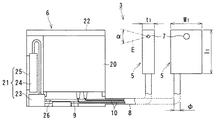
図1は本発明に係る放射線非破壊検査装置の第1の実施形態を示す構成図である。
【0026】
放射線非破壊検査装置1は、放射線であるX線Eを被検体の一例である配管2に向けて放射する放射線発生装置を構成する放射線源であるX線源3と、配管2を透過したX線Eを検出する放射線検出器としての平面検出器4とを具備する。
【0027】
X線源3はX線発生装置を構成しており、X線Eを放射するための照射ヘッド5とこの照射ヘッド5を油冷ないし制御するための放射線コントローラの一例としてのX線コントローラ6と、X線コントローラ6からの高電圧印加によりX線を生成するX線管7とを具備する。このため、照射ヘッド5およびX線管7とX線コントローラ6とはフレキシブルガイドホース8により保護された油冷ホース9および電源ケーブル10を介して接続される。X線源3の照射ヘッド5にはX線管7が設けられ、X線管7からX線Eが放射される。さらに、照射ヘッド5には油冷循環パイプ11が設けられ、この油冷循環パイプ11に油冷ホース9が接続される。
【0028】
そして、X線源3の照射ヘッド5は、配管2の検査部位にX線管7を向けてX線Eを照射可能な向き及び位置で配置される一方、平面検出器4は、X線源3から配管2に照射されて透過したX線Eを検出することができる位置、すなわち配管2を挟んでX線源3に対向する位置に設けられる。
【0029】
平面検出器4は容器状の遮蔽材12の内部に電気回路13を設けた構成である。この、電気回路13は遮蔽材12によりX線Eから遮蔽されて保護される。さらに、平面検出器4のX線源3側における所要の位置には、X線源3側から板状のシンチレータ14、光学素子の一例であるファイバオプティックプレート(Fiber optic plate)15、受光素子の一例であるCMOS(相補型金属酸化膜半導体:Complementary Metal Oxide Semiconductor)センサ16が重ね合わさった状態で設けられる。
【0030】
そして、平面検出器4のシンチレータ14のX線源3側の面はX線検出面17を形成し、このX線検出面17がX線Eの進行方向に対して所要の角度、例えば垂直となる向きとなるように平面検出器4が配置される。
【0031】
また、X線源3の照射ヘッド5に設けられたX線管7近傍にはマスク用冶具18が移動可能に設けられる。マスク用冶具18は例えば、所要の貫通孔あるいはスリットを有する板状あるいはブロック状の鉛シャッタにより構成される。さらに、マスク用冶具18の貫通孔あるいはスリットのサイズは調整可能であり、このマスク用冶具18を移動させるとともに貫通孔あるいはスリットのサイズを調整することにより、X線源3から照射されるX線Eの領域を調節することができるように構成される。
【0032】
尚、マスク用冶具18が設けられる位置は、X線管7近傍に限らずX線Eの照射経路上であれば任意である。
【0033】
さらに、平面検出器4とX線源3の照射ヘッド5との間すなわちX線Eの照射経路上には、検査の際、配管2の所要の部位のサイズを判断し校正するためのペネトラメータ19が設けられる。このペネトラメータ19は、例えば1cm間隔のメモリを有するメジャーで構成される。そして、ペネトラメータ19は、X線源3から配管2に向かって照射されたX線Eの一部が透過して平面検出器4において検出可能な位置に配置される。
【0034】
次にX線源3の詳細構成および機能について説明する。
【0035】
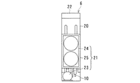
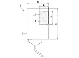
図2は、図1に示すX線源3の詳細構成の一例を示す正面図、図3は図2に示すX線コントローラ6の上面図、図4は図2に示すX線コントローラ6の左側面図である。
【0036】
X線源3はX線Eを放射するための照射ヘッド5、X線管7およびX線コントローラ6を具備する。そして、照射ヘッド5およびX線管7とX線コントローラ6とはフレキシブルガイドホース8により保護された油冷ホース9および電源ケーブル10を介して接続される。
【0037】
X線源3のX線コントローラ6には、照射ヘッド5の運転状態を制御するための高圧電源20が備えられる。そしてこの高圧電源20は電源ケーブル10を介して照射ヘッド5に接続され、遠隔から電力を負荷することにより照射ヘッド5におけるX線管7のオンオフ操作を行うことができるように構成される。
【0038】
一方、照射ヘッド5からX線Eが放射される際には熱が生じて照射ヘッド5が加熱される。そこで、照射ヘッド5を冷却するための冷却ユニット21がX線コントローラ6に併設される。X線コントローラ6と冷却ユニット21は単一の樹脂カバー22により保護されて一体化される。
【0039】
また、X線コントローラ6に設けられた冷却ユニット21は、ポンプ23、ラジエータ24およびファン25を具備する。冷却ユニット21のポンプ23は油冷ホース9を介して照射ヘッド5と接続され、ポンプ23から絶縁性の冷却油26が油冷ホース9を介して照射ヘッド5に与えられて照射ヘッド5が冷却されるように構成される。
【0040】
さらに、照射ヘッド5を冷却することにより加熱された冷却油26は再び油冷ホース9を介して冷却ユニット21のラジエータ24に導かれ、ファン25の作用により空冷される。冷却ユニット21のラジエータ24で空冷された冷却油26は再び冷却ユニット21のポンプ23に導かれる。
【0041】
すなわち、照射ヘッド5は、冷却ユニット21および油冷ホース9を循環する冷却油26により冷却されるように構成される。ただし、冷却油26の代わりに絶縁性の水やその他の液体、気体を用いてもよい。
【0042】
一方、X線源3の照射ヘッド5は、小型の例えば縦寸法がl1=300mm、横寸法がw1=210mm、厚さがt1=85mmの板状とされ、照射ヘッド5の運搬を容易にすることができるのみならず、被検査体となる配管2が狭隙部に存在しても容易に照射ヘッド5を配管2近傍に配置できるように構成される。さらに、照射ヘッド5にはX線管7が設けられ、X線管7からは所要のビーム開き角度αの例えば32.0度のX線Eを放射させることができる。
【0043】
また、照射ヘッド5の配置をより容易にするために、照射ヘッド5とX線コントローラ6とを接続する油冷ホース9および電源ケーブル10を保護するためのフレキシブルガイドホース8は小径、例えばφ=40mmとされる。
【0044】
尚、照射ヘッド5のX線管7以外の構成部分をX線コントローラ6に備える一方、照射ヘッド5をX線管7のみで構成することにより、照射ヘッド5をさらに小型化することも可能である。
【0045】
すなわち、X線源3は、電力を負荷するための高圧電源20と照射ヘッド5を冷却するための冷却ユニット21とをX線Eの放射により加熱され、冷却が必要であるため小型化が困難な照射ヘッド5から切離し、別々の構成としてフレキシブルガイドホース8介して接続することにより照射ヘッド5の小型化を可能とする構成である。
【0046】
このため、照射ヘッド5のケースに用いられる鉛遮蔽体の量が低減されて照射ヘッド5の総合重量を減少させることが可能となる。
【0047】
さらに、X線源3は、高圧電源20および冷却ユニット21を一体化することにより、構成部品数の低減を図ったものである。
【0048】
次に平面検出器4の具体的な形状例および各構成の機能について説明する。
【0049】
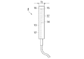
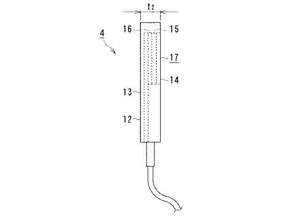
図5は図1に示す平面検出器4の具体的な寸法および形状の一例を示す正面図であり、図6は図5に示す平面検出器4の左側面図である。
【0050】
平面検出器4は例えば、図5および図6に示す寸法および形状で構成される。
【0051】
平面検出器4は、例えば縦寸法がl2=178mm、横寸法がw2=125mm、厚さ寸法がt2=23mmの板状に構成される。そして、平面検出器4のX線源3側の面の所要の位置、例えば図5において右上部分にシンチレータ14が設けられ、シンチレータ14によりX線検出面17が形成される。
【0052】
平面検出器4のシンチレータ14により形成されるX線検出面17は、例えば縦寸法l3が75mmで横寸法w3が50mmの長方形状平面とされ、平面検出器4はこのX線検出面17のエリアにおいてX線Eを受けることにより検出することができるように構成される。
【0053】
平面検出器4のシンチレータ14は、X線Eを受けると反応して発光する蛍光体を具備する。シンチレータ14はX線Eを受けると可視光に変換し、変換した可視光を平面検出器4のファイバオプティックプレート15に与える機能を有する。
【0054】
ただし、このときシンチレータ14においてX線Eの一部は可視光に変換されずに透過して平面検出器4のファイバオプティックプレート15に入射する。
【0055】
平面検出器4のファイバオプティックプレート15は、例えば石英ファイバで構成された光ファイバを束ねることにより形成される。そして、ファイバオプティックプレート15は、シンチレータ14がX線Eを受けることにより生じた可視光を受けるとともに平面検出器4のCMOSセンサ16に伝送して与える一方、シンチレータ14を透過したX線Eを吸収し、あるいは散乱させる機能を有する。
【0056】
さらに、平面検出器4のCMOSセンサ16は、ファイバオプティックプレート15から受けた可視光を受光して電気信号に変換し、変換した電気信号を平面検出器4の遮蔽材12内部の電気回路13に与える機能を有する。すなわちCMOSセンサ16は、ファイバオプティックプレート15から受けた可視光をデジタル画像情報に変換することができる。
【0057】
平面検出器4の遮蔽材12内部の電気回路13は、CMOSセンサ16から受けたデジタル画像情報である電気信号を画像表示可能な情報に処理し、図示しないモニタに送信する機能を有する。そして、図示しないモニタにおいて、被検体である配管2の内部構造、欠陥等の形状の画像を得ることができるように構成される。
【0058】
尚、平面検出器4のシンチレータ14に強度のX線Eが入射すると、シンチレータ14において高強度の可視光が変換される。そして、シンチレータ14において変換された高強度の可視光はファイバオプティックプレート15を経由した後、CMOSセンサ16において乱反射し、モニタで得られる結像をにじませるいわゆるハレーションが引き起こされる。
【0059】
そこで、図1に示すようにX線源3のX線管7近傍に設けられたマスク用冶具18によりX線源3から照射されるX線Eの領域が配管2の形状に応じて調節され、X線源3から照射されるX線Eが、配管2を経由せずに平面検出器4のシンチレータ14に到達しないように調節されて、ハレーションの発生が抑制される。
【0060】
また、X線源3から照射されるX線Eが配管2を経由しても、配管2を構成する部材の厚さが薄くX線Eの透過率が大きい部位と、配管2を構成する部材の厚さが厚くX線Eの透過率が小さい部位とが混在する場合において、X線Eの透過率が小さい部位に照射するX線Eの強度を合わせると、X線Eの透過率が大きい部位を透過したX線Eの強度が強くなってハレーションが引き起こされる要因となる。
【0061】
このため、被検体のX線Eの透過率が小さい部位においてもマスク用冶具18を調節することにより、被検体を透過してシンチレータ14に到達するX線Eの強度が適宜調節される。
【0062】
すなわち、平面検出器4は、シンチレータ14においてX線Eを受けて可視光に変換し、変換された可視光をCMOSセンサ16において受光するとともに電気信号に変換して電気回路13に与える構成である。そして、電気回路13において電気信号に変換されたX線Eを画像表示可能な情報に処理して図示しないモニタに送信する構成である。
【0063】
さらにこのとき、CMOSセンサ16にX線Eが入射するとCMOSセンサ16が損傷し、CMOSセンサ16の感度が低下する恐れがあるため、CMOSセンサ16とシンチレータ14との間に、放射線吸収ないし散乱メンバーとしてのファイバオプティックプレート15を設け、ファイバオプティックプレート15によりシンチレータ14を透過したX線Eを吸収し、あるいは散乱させてCMOSセンサ16に入射するX線Eの量を低減させることにより、CMOSセンサ16の損傷を抑制する構成である。
【0064】
ここで、シンチレータ14を透過したX線Eはファイバオプティックプレート15に入射するが、ファイバオプティックプレート15を構成する石英ファイバ等の光ファイバにX線Eやγ線等の放射線が照射されると光ファイバのカラーセンタが変わり、光ファイバすなわちファイバオプティックプレート15において吸収される放射線の波長領域が変化する。
【0065】
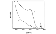
図7は、放射線を照射する前後における光ファイバに入射した光の波長と光ファイバに入射した光の相対吸収率との関係を示す図である。
【0066】
図7において、横軸は光ファイバに入射した光の波長を示し、縦軸は光ファイバに入射した光の相対吸収率を示す。図7中、一点鎖線は光ファイバに放射線を照射する前における光ファイバによる光の相対吸収率曲線Aを示し、実線は光ファイバに放射線を照射した後における光ファイバによる光の相対吸収率曲線Bを示す。
【0067】
図7の光ファイバに放射線を照射する前の光ファイバによる光の相対吸収率曲線Aによれば、光ファイバの相対吸収率は光の波長が短くなるにつれて増加し、特に光の波長が450nmよりも短波長となり紫外領域に近づくにつれて著しく光の吸収率が増加している。
【0068】
一方、光ファイバに放射線を照射した後における光ファイバによる光の相対吸収率曲線Bによれば、光ファイバの相対吸収率は光の波長が短くなるにつれて増加するものの、光ファイバに放射線を照射する前の光ファイバによる光の相対吸収率よりも増加している。すなわち、光ファイバに放射線を照射することにより光ファイバの光の吸収率が増加し、光の透過率が減少したことが分かる。
【0069】
また、光ファイバに放射線を照射した後の光の相対吸収率曲線Bによれば、光の相対吸収率は、光の波長が600nm付近となる場合において極大値となり光ファイバに放射線を照射することによる光の吸収率の増加量が顕著であることが分かる。
【0070】
さらに、光の波長が700nm付近となる場合において、放射線を照射した後の光ファイバの光の相対吸収率は極小値となるのみならず、光ファイバに放射線を照射することによる光の吸収率の増加量が他の光の波長領域よりも著しく少ないことが分かる。
【0071】
一方、CMOSセンサ16あるいはCCD(Charge coupled device)センサ等の半導体受光素子が光を受光する際の感度は、受光する光の波長に依存する。
【0072】
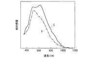
図8は、CCDセンサの感度とCCDセンサが受光する光の波長との関係を示す図である。
【0073】
図8において、縦軸はCCDセンサの相対感度を示し、横軸はCCDセンサが受光する光の波長を示す。さらに、図8の実線は赤色領域の光に高感度を有するCCDセンサのCCDセンサ感度特性曲線Cを示し、一点鎖線は緑色領域の光に高感度を有するCCDセンサのCCDセンサ感度特性曲線Dを示す。
【0074】
図8に示す各CCDセンサのそれぞれのCCDセンサ感度特性曲線C、Dは、いずれも同様な傾向を示し、CCDセンサが受光する光の波長が450nmから700nm程度の範囲となる場合に、相対感度が増加し最大値あるいは極大値となるが、相対感度の最大値とそのときの光の波長が相違する。
【0075】
すなわち、実線で示すCCDセンサ感度特性曲線Cから赤色領域の光に高感度を有するCCDセンサの相対感度は、光の波長が650nm程度である赤色領域の光を受光する場合において最大値となる一方、一点鎖線で示すCCDセンサ感度特性曲線Dから緑色領域の光に高感度を有するCCDセンサの相対感度は、光の波長が500nm程度の緑色領域の光を受光する場合において最大値となることが分かる。
【0076】
さらに、各CCDセンサ感度特性曲線C、Dの最大値を比較すると、赤色領域の光に高感度を有するCCDセンサの相対感度のほうが、緑色領域の光に高感度を有するCCDセンサの相対感度よりも良好であることが分かる。
【0077】
加えて、450nm程度から650nm程度の範囲における波長の可視光に対しては、赤色領域の光に高感度を有するCCDセンサの相対感度が、常に緑色領域の光に高感度を有するCCDセンサの相対感度の最大値よりも大きい。
【0078】
したがって、CCDセンサやCMOSセンサ16等の半導体受光素子が光を受光する際の感度は、半導体受光素子が受光する光が赤色領域である場合のほうが、緑色領域あるいはさらに短波長の青色領域の光を受光する場合よりも良好であることが理解できる。
【0079】
以上のことから、放射線非破壊検査装置1の平面検出器4においては、ファイバオプティックプレート15にX線Eが照射されてもファイバオプティックプレート15の光の透過率の低下量が小さくかつCMOSセンサ16の感度が良好となる光の波長領域をシンチレータ14から発生させるために、シンチレータ14には、X線Eを受けると赤色領域で発光する蛍光体、すなわち赤色タイプの蛍光体が使用される。
【0080】
さらに、この赤色タイプの蛍光体に、ランタノイド元素列の元素、例えばユウロピウム(Eu)元素等の賦活剤を所要量添加することにより蛍光体から生じる光の波長を調整し、ファイバオプティックプレート15における光の吸収率のより小さい可視光を発生させることが可能となる。
【0081】
賦活剤としてユウロピウム(Eu)を蛍光体に添加すると賦活剤が添加されない場合には本来禁制遷移の励起レベルで蛍光体の結晶場を励起させることが可能となる。例えば、ユウロピウム(Eu)を添加した蛍光体においては、式(1)ないし式(2)に示す励起により式(1)ないし式(2)に示す波長の光を発光させることができる。
【0082】
【数1】
一方、半導体受光素子には、受光する光の波長に対する感度特性が赤色領域と異なるCCDセンサ、CMOSセンサ16あるいはTFT(Thin Film Transistor)型センサ等の光電変換素子がある。これらの光電変換素子には、例えば、赤色領域の波長の光に対する感度と同等以上の感度を赤色領域近傍の波長の光あるいは緑色領域の波長に光に対して有するものがある。
【0084】
そこで、光の各波長領域に感度を有する半導体受光素子の感度特性に対応させるため、赤色タイプの蛍光体に添加する賦活剤の濃度を調節することにより緑色成分や青色成分の量を加減することができる。
【0085】
赤色タイプの蛍光体に添加する賦活剤の例としては、ユウロピウム(Eu)の他に、緑色成分を主成分とする光を発光させることができるテルビウム(Tb)やプラセオジム(Pr)等のらんランタノイド元素が挙げられる。
【0086】
次に放射線非破壊検査装置1の作用について説明する。
【0087】
X線源3の照射ヘッド5が、被検体である配管2の検査部位にX線管7を向けてX線Eを照射可能な向き及び位置で配置される。照射ヘッド5は高圧電源20と冷却ユニット21から分離されて構成され、小型化されているため、配管2が狭隙部であっても容易に配置することができる。
【0088】
一方、照射ヘッド5から配管2に照射されて透過したX線Eを検出することができる位置、すなわち配管2を挟んで照射ヘッド5に対向する位置に平面検出器4が設けられる。このとき、平面検出器4のシンチレータ14のX線源3側の面であるX線検出面17は、X線Eの進行方向に対して所要の角度、例えば垂直となる向きとされる。
【0089】
また、照射ヘッド5のX線管7近傍には所要の貫通孔あるいはスリットを有する板状あるいはブロック状のマスク用冶具18が移動可能に設けられる。マスク用冶具18の貫通孔あるいはスリットのサイズを調整することにより、照射ヘッド5から照射されるX線Eの領域が調節され、平面検出器4におけるハレーションの発生が抑制される。
【0090】
さらに、平面検出器4と照射ヘッド5との間には、検査の際、配管2の所要の部位のサイズを判断し校正するためのペネトラメータ19が設けられる。
【0091】
次に、X線源3のX線コントローラ6が具備している高圧電源20から照射ヘッド5に電源ケーブル10を介して電力が与えられ、照射ヘッド5のX線管7からX線Eが配管2に向かって照射される。このとき、X線Eの領域はマスク用冶具18により調節される。
【0092】
一方、X線源3の冷却ユニット21と照射ヘッド5との間を油冷ホース9を介して循環する冷却油26により、X線Eの発生に伴って加熱された照射ヘッド5が冷却される。
【0093】
さらに、X線源3の照射ヘッド5から配管2に照射され、配管2を透過したX線Eは平面検出器4のシンチレータ14に入射する。このとき、X線源3の照射ヘッド5から照射されたX線Eの一部は、ペネトラメータ19を透過して平面検出器4のシンチレータ14に入射する。
【0094】
平面検出器4のシンチレータ14は、赤色タイプの蛍光体を具備し、さらに、この赤色タイプの蛍光体には、ユウロピウム(Eu)元素等の賦活剤が所要量添加され、ファイバオプティックプレート15における光の吸収率がより小さく、かつCMOSセンサ16の感度がより良好となる波長領域の可視光を発生させるように調整されている。このため、シンチレータ14の蛍光体は、X線Eを受けると反応してファイバオプティックプレート15における光の吸収率がより小さく、かつCMOSセンサ16の感度がより良好となる波長領域の赤色領域の可視光を発生させる。そして、発生した赤色領域の可視光は、シンチレータ14を透過したX線Eとともにファイバオプティックプレート15に入射する。
【0095】
平面検出器4のファイバオプティックプレート15は、シンチレータ14から受けた赤色領域の可視光とシンチレータ14を透過したX線Eとを受けると、赤色領域の可視光をCMOSセンサ16に伝送して与える一方、X線Eを吸収し、あるいは散乱させる。このため、CMOSセンサ16に入射するX線Eの量が低減され、CMOSセンサ16の損傷が抑制される。
【0096】
このとき、ファイバオプティックプレート15にX線Eが照射されることによりファイバオプティックプレート15の可視光の吸収率が増加する。このため、ファイバオプティックプレート15において可視光の一部も吸収されるが、可視光はファイバオプティックプレート15における光の吸収率がより小さい赤色領域に調整されており、他の領域の可視光よりも吸収率が少ないため、より強い光量の可視光がファイバオプティックプレート15を透過しCMOSセンサ16に伝送される。
【0097】
平面検出器4のCMOSセンサ16は、ファイバオプティックプレート15から赤色領域の可視光を受光すると電気信号のデジタル画像情報に変換し、変換したデジタル画像情報を電気回路13に与える。ここで、CMOSセンサ16は、緑色領域の可視光に高感度を有するCCDセンサよりも相対感度が良好な赤色領域の可視光に感度を有するCMOSセンサ16であり、かつCMOSセンサ16の感度がより良好となる波長領域に調整された赤色領域の可視光が受光されるため、より良好な感度で可視光が電気信号に変換される。
【0098】
さらに、電気回路13は、CMOSセンサ16から受けたデジタル画像情報を画像表示可能な情報に処理し、図示しないモニタに送信する。
【0099】
この結果、図示しないモニタにおいて、被検体である配管2の内部構造、欠陥等の形状の画像を破壊することなく得ることができる。さらに、モニタには配管2の画像とともにペネトラメータ19の画像が表示されるため、ペネトラメータ19を利用して、配管2の欠陥部等の所要部位におけるサイズを求めることができる。
【0100】
次に、放射線非破壊検査装置1で得られる画像の例について説明する。
【0101】
図9は、図1に示す放射線非破壊検査装置1で配管2の溶接部にX線Eを照射することにより得られた画像の一例を示す図である。
【0102】
図9に示すように放射線非破壊検査装置1により配管2を透過したX線Eを可視光に変換して得られた画像が、図示しないモニタに表示される。図9から、配管2の溶接部に溶接の溶け込み不足を確認することができる。
【0103】
また、図9において中央部には、配管2の検査をする際に配管2の妥当性を確認するためのペネトラメータ19の画像30が配管2とともに水平方向に撮影されて表示されているため、このペネトラメータ19の画像30のメモリの間隔と平面検出器4の測定画素数の間隔とに基づいて配管2の欠陥部等の任意の部位の寸法をより高精度で校正して求めることができる。
【0104】
このため、配管2の溶接部において溶け込み不足となっている部位の大きさは1mm程度であるという結果を得ることができる。
【0105】
すなわち放射線非破壊検査装置1は、平面検出器4のCMOSセンサ16とシンチレータ14との間にファイバオプティックプレート15を設けてX線Eを吸収させることにより、CMOSセンサ16に入射するX線Eの量を低減させて損傷を抑制し、CMOSセンサ16の感度の低下を回避させる一方、シンチレータ14に赤色タイプの蛍光体を設け、ファイバオプティックプレート15にX線Eが入射してファイバオプティックプレート15における可視光の透過率が減少してもより可視光の透過率の減少量が小さくかつCMOSセンサ16の感度がより良好な赤色領域の可視光を発生させることにより、より良好な感度で被検体の画像を得るものである。
【0106】
また、例えば配管2のような狭間部に配置された被検体であっても、容易に被検体にX線Eを照射できるようにするために、X線源3の照射ヘッド5を高圧電源20と冷却ユニット21から分離して構成することにより小型化したものである。
【0107】
放射線非破壊検査装置1では、被検体に照射されて被検体を透過したX線Eをより高感度で精度よく効率的に可視光ないしデジタル画像情報に変換して画像化することができる。このため、より低エネルギないし低線量のX線Eで短時間に被検体の撮像が可能となる。
【0108】
さらに、放射線非破壊検査装置1では、CMOSセンサ16により可視光を受光して現像することなくデジタル画像情報に変換する構成であるため、被検体に照射されて被検体を透過したX線Eをより短時間で画像化できる。
【0109】
このため、特に医療用の被破壊検査の場合には、被検体である患者の被曝量を低減させることができる。
【0110】
一方、工業用の被破壊検査の場合には、従来は放射線源から被検体に照射されて透過したX線EをX線フィルムで可視光を受光して現像させる方法により非破壊検査が行われていたため、X線フィルムの現像や乾燥に長時間要し、検査結果をリアルタイムに得ることが不可能であった。さらに、被検体のX線撮影に失敗した場合には、再度撮影が必要となり検査時間及び検査労力の増加要因となっていた。
【0111】
しかし、放射線非破壊検査装置1では、CMOSセンサ16により可視光を受光して現像することなくデジタル画像情報に変換する構成であるため、被検体の検査現場においてリアルタイムあるいは迅速に検査結果を得るとともに検査結果を判断することができる。
【0112】
また、放射線非破壊検査装置1では、CMOSセンサ16に入射するX線Eの量が低減されるため、CMOSセンサ16のX線Eによる損傷が抑制され、CMOSセンサ16の寿命を増加させることができる。
【0113】
また、放射線非破壊検査装置1では、例えば配管2のような狭間部に配置された被検体であっても、容易に被検体にX線Eを照射して非破壊的に被検体を検査することができる。
【0114】
図10は本発明に係る放射線非破壊検査装置の第2の実施形態を示す構成図である。
【0115】
図10に示された、放射線非破壊検査装置1Aでは、平面検出器4とX線源3とを一体化するとともに移動機構40に設け、さらにこの移動機構40に情報制御サーバ41とモニタ42を備えたクライアント43を接続した構成が図1に示す放射線非破壊検査装置1と相違している。平面検出器4とX線源3の構成および作用については図1に示す放射線非破壊検査装置1と実質的に異ならないため同符号を付して説明を省略する。
【0116】
放射線非破壊検査装置1Aは、多関節アーム44を備えた移動機構40を有する。移動機構40は走行手段、例えば車輪45を備えており任意方向に移動可能に構成される。さらに、移動機構40の多関節アーム44は、単一あるいは複数の関節部分46を有するアーム状の構成であり、この多関節アーム44の所要の位置、例えば多関節アーム44の先端部分に平面検出器4とX線源3の照射ヘッド5とが位置決めされて一体に固定される。
【0117】
そして、平面検出器4とX線源3の照射ヘッド5の相対的な位置関係が幾何学的に一定とされ、一体化された平面検出器4および照射ヘッド5が互いの相対的な位置関係を変えることなく任意の向き及び高さとなるように位置決めすることができるように構成される。
【0118】
さらに、X線源3のX線コントローラ6は、任意の位置例えば、移動機構40に内蔵され、遠隔からX線源3の照射ヘッド5の冷却およびX線Eのオンオフ等の操作を可能に構成し、同時に照射ヘッド5が小型化される。
【0119】
また、平面検出器4とX線源3とを備えた移動機構40には、情報制御サーバ41が接続され、情報制御サーバ41には任意数のモニタ42を備えたクライアント43がそれぞれ接続されて任意の場所に設けられる。
【0120】
一方、平面検出器4とX線源3の照射ヘッド5との間には、マスク用冶具18が移動可能に設けられ、X線源3の照射ヘッド5から照射されるX線Eの領域を調節することによりハレーションが生じないように構成される。尚、マスク用冶具18を制御するために別途、アーム等の制御機構を移動機構40に設けてもよい。
【0121】
また、平面検出器4とX線源3の照射ヘッド5との間、例えば照射ヘッド5には、検査の際、配管2の所要の部位のサイズを判断し校正するためのペネトラメータ19が設けられる。
【0122】
図11は図10に示す放射線非破壊検査装置1Aの移動機構40に接続される情報制御サーバ41の機能ブロック図である。
【0123】
情報制御サーバ41は、移動機構制御手段41a、放射線制御手段41b、画像入力手段41c、画像出力手段41d、放射線照射表示手段41e、欠陥部表示手段41f、欠陥部寸法算出手段41g、欠陥部基準値表示手段41h、欠陥部判定手段41i、基準画像表示手段41j、欠陥部情報ファイル編集手段41k、通信手段41lを具備する。
【0124】
情報制御サーバ41の移動機構制御手段41aは、クライアント43から入力された制御情報により遠隔から移動機構40の車輪45および多関節アーム44を制御し、平面検出器4とX線源3とを所要の位置に所要の向きで位置決めする機能を有する。
【0125】
情報制御サーバ41の放射線制御手段41bは、クライアント43から入力された制御情報により遠隔からX線源3のX線コントローラ6を制御し、照射ヘッド5から放射されるX線EおよびX線源3の照射ヘッド5を冷却するための冷却ユニット21のオンオフ等の操作を行う機能を有する。
【0126】
情報制御サーバ41の画像入力手段41cは、平面検出器4の電気回路13から被検体の画像情報である電気信号を入力して画像出力手段41d、放射線照射表示手段41e、欠陥部表示手段41fおよび基準画像表示手段41jに与える機能を有する。
【0127】
情報制御サーバ41の画像出力手段41dは、画像入力手段41cから受けた被検体の画像情報をモニタ42に与えることにより表示させる機能を有する。
【0128】
また、移動機構40や情報制御サーバ41あるいはその他の任意の場所には、表示器の例として任意数のランプ47およびブザー48が設けられる。
【0129】
そして、情報制御サーバ41の放射線照射表示手段41eは、画像入力手段41cから被検体の画像情報を受けるとランプ47およびブザー48に動作指令情報を与える機能を有する。
【0130】
ランプ47は、情報制御サーバ41の放射線照射表示手段41eから動作指令情報を受けると点灯ないし点滅するように構成され、ランプ47の点灯ないし点滅により作業者は平面検出器4がX線Eを検出している状態であることを知ることができる。一方、ブザー48は放射線照射表示手段41eから動作指令情報を受けると動作音を発生させるように構成され、作業者はブザー48の動作音により平面検出器4がX線Eを検出している状態であることを知ることができる。
【0131】
すなわち、作業者を被曝から回避させるために、ランプ47の点灯ないし点滅およびブザー48の動作音により、X線源3からX線Eが照射されている状態であることを作業者が知ることができるように構成される。
【0132】
また、情報制御サーバ41の欠陥部表示手段41fは、画像入力手段41cから被検体の画像情報を受けると、この画像情報に基づいて自動的に被検体の欠陥部を判別する機能と、判別した結果、欠陥部が存在する場合には欠陥部をマーキング表示するためのマーキング情報を作成して欠陥部情報ファイルを作成し、モニタ42に表示させる機能を有する。
【0133】
欠陥部表示手段41fによる被検体の欠陥部を判別する方法としては、例えば画像情報の濃淡を数値化し、所定の基準値と比較することにより欠陥部の有無および範囲を判別する方法が挙げられる。
【0134】
さらに、欠陥部表示手段41fは、被検体に欠陥部が存在する場合には、被検体の画像情報とともに欠陥部情報ファイルを欠陥部寸法算出手段41gに与える機能を有する。
【0135】
情報制御サーバ41の欠陥部寸法算出手段41gは、欠陥部表示手段41fから被検体の画像情報および欠陥部情報ファイルを受けると、被検体の欠陥部の面積や任意方向の長さ等の寸法を算出する機能、算出した被検体の欠陥部の寸法を欠陥部情報ファイルに書き込むとともに、欠陥部情報ファイルをモニタ42に表示する機能および被検体の欠陥部の寸法情報を加えた欠陥部情報ファイルを欠陥部基準値表示手段41hに与える機能を有する。
【0136】
情報制御サーバ41の欠陥部基準値表示手段41hには、予め被検体の部位に応じた欠陥部の寸法の品質および機能に対する良否の判定基準値である寸法基準値情報が保存される。そして、欠陥部寸法算出手段41gから被検体の欠陥部の寸法情報を含む欠陥部情報ファイルを受けると、被検体の欠陥部に応じた欠陥部の寸法基準値情報を欠陥部情報ファイルに追加して欠陥部判定手段41iに与えるとともにモニタ42に表示する機能を有する。
【0137】
このため、作業者は、欠陥部基準値表示手段41hによりモニタ42に表示された欠陥部情報ファイルの被検体の欠陥部の寸法情報と寸法基準値情報とを比較することにより、被検体の欠陥部が所要の品質および機能を具備しているか否かを判断することができる。
【0138】
情報制御サーバ41の欠陥部判定手段41iは、欠陥部基準値表示手段41hから受けた被検体の欠陥部の寸法情報と寸法基準値情報とを比較することにより、被検体の欠陥部が被検体の品質および機能に影響を与えるか否か、すなわち検査結果の良否を自動的に判定する機能と、被検体の欠陥部の寸法が寸法基準値の範囲外であり被検体が不良と判断された場合には、ランプ47およびブザー48に動作指令情報を与える機能を有する。
【0139】
ランプ47およびブザー48は、欠陥部判定手段41iから動作指令情報を受けるとそれぞれ点灯あるいは点滅ないし動作音を発生させるように構成され、作業者は、ランプ47およびブザー48の点灯あるいは点滅ないし動作音により被検体の良否を知ることができる。
【0140】
情報制御サーバ41の基準画像表示手段41jには、例えば予め被検体の各部位における欠陥が存在しない正常な状態の画像情報が基準画像情報として保存される。基準画像表示手段41jは、画像入力手段41cから被検体の画像情報を受けると、受けた画像情報に相当する被検体の部位における基準画像情報をモニタ42に表示させる機能を有する。
【0141】
被検体の基準画像情報は、前回あるいは最近被検体を検査した際の被検体の画像情報や被検体の使用開始時における未使用状態の画像情報とすることにより、経年変化のように次第に被検体の品質や機能が劣化する場合の判断が容易となる。
【0142】
すなわち、基準画像情報は、X線Eによる撮影で得られた画像情報の比較対象となる画像情報であれば任意である。
【0143】
このため、作業者は、画像出力手段41dによりモニタ42に表示された被検体の検査による撮影結果である画像情報と基準画像表示手段41jにより表示された基準画像情報とを比較することにより、被検体が所要の品質および機能を具備しているか否かを判断することができる。
【0144】
情報制御サーバ41の欠陥部情報ファイル編集手段41kは、欠陥部情報ファイルに任意の記録内容を書き込んで情報を追加する機能を有する。このため、作業者は、基準画像情報と測定して得られた画像情報とを比較して被検体が所要の品質および機能を具備しているか否かを判断する際、判断が困難な場合や特記事項がある場合には状況を文章として記録することができる。
【0145】
情報制御サーバ41の通信手段41lは、欠陥部情報ファイルおよび配管2の画像情報を所要の場所に設けられたクライアント43に送受信する機能を有する。このため、被検体の判断が困難であっても、被検体の状況を記録した編集後の欠陥部情報ファイルおよび配管2の画像情報を所要の判断技術を有する検査員や監視員あるいは被検体の製造工場の技術者が有するクライアント43に送信することにより遠隔から被検体の品質および機能をより適切かつ迅速に判断することができるように構成される。
【0146】
次に、放射線非破壊検査装置1Aの作用について説明する。
【0147】
図12は、図10に示す放射線非破壊検査装置1Aにより被検体の検査をする際の流れを示すフローチャートである。
【0148】
まずステップS1において、クライアント43から制御情報を入力して情報制御サーバ41の移動機構制御手段41aにより移動機構40の車輪45および多関節アーム44を遠隔制御することにより、被検体である配管2にX線Eを照射し、かつ配管2を透過したX線Eを検出可能な位置に一体化された平面検出器4とX線源3の照射ヘッド5とを位置決めする。
【0149】
さらに、平面検出器4とX線源3の照射ヘッド5との間にマスク用冶具18を設け、マスク用冶具18を調節することにより、X線源3の照射ヘッド5から照射されるX線Eの領域および平面検出器4に到達するX線Eの強度が調整されてハレーションの発生が抑制される。
【0150】
また、平面検出器4とX線源3の照射ヘッド5との間、例えばX線源3の照射ヘッド5には、検査の際、配管2の所要の部位のサイズを判断し校正するためのペネトラメータ19が設けられる。
【0151】
次に、ステップS2では、クライアント43から制御情報を入力して情報制御サーバ41の放射線制御手段41bによりX線源3のX線コントローラ6を制御することによりX線源3の照射ヘッド5からX線Eを配管2に向かって放射させ、かつ冷却ユニット21を作動させて照射ヘッド5を冷却する。
【0152】
このため、ステップS3において、平面検出器4により配管2を透過したX線Eが検出されて可視光に変換された後、さらに電気回路13において画像情報の電気信号に変換される。
【0153】
そして、ステップS4では、情報制御サーバ41の画像入力手段41cが、平面検出器4の電気回路13から配管2の画像情報である電気信号を入力して画像出力手段41d、放射線照射表示手段41e、欠陥部表示手段41fおよび基準画像表示手段41jに与える。
【0154】
さらに、ステップS5では、画像出力手段41dは、画像入力手段41cから受けた配管2の画像情報をモニタ42に与えることにより表示させる一方、放射線照射表示手段41eは、画像入力手段41cから被検体の画像情報を受けるとランプ47およびブザー48に動作指令情報を与え、ランプ47およびブザー48を作動させる。このため、作業者は、X線源3の照射ヘッド5からX線Eが放射されていることを知ることができるとともに、放射されたX線Eにより撮影された配管2の画像を遠隔からモニタ42で見ることができる。
【0155】
また、ステップS6において、欠陥部表示手段41fが、画像入力手段41cから受けた画像情報に基づいて自動的に配管2の欠陥部を自動判別し、欠陥部をマーキング表示するためのマーキング情報を作成して欠陥部情報ファイルを作成する。そして、欠陥部表示手段41fにより作成された欠陥部情報ファイルおよび配管2の画像情報は欠陥部寸法算出手段41gおよびモニタ42に与えられ、モニタ42において配管2の欠陥部がマーキング表示される。
【0156】
このため、作業者はモニタ42から配管2の画像を検討して判断することなく容易に配管2の欠陥部を確認することができる。さらに、モニタ42には配管2の画像とともにペネトラメータ19の画像が表示されるため、作業者は配管2の欠陥部の大きさを把握することができる。
【0157】
そして、ステップS7では、欠陥部寸法算出手段41gが、欠陥部表示手段41fから受けた欠陥部情報ファイルおよび配管2の画像情報から配管2の欠陥部の面積や任意方向の寸法等の大きさを自動計算して欠陥部情報ファイルに書き込むとともに、欠陥部情報ファイルをモニタ42および欠陥部基準値表示手段41hに与える。このため作業者は、モニタ42から配管2の欠陥部の大きさを容易に知ることができる。
【0158】
さらに、ステップS8では、欠陥部基準値表示手段41hが、欠陥部寸法算出手段41gから受けた配管2の欠陥部の寸法情報を含む欠陥部情報ファイルに基づいて、欠陥部が存在する配管2の部位における欠陥部の判定基準値である寸法基準値情報を欠陥部情報ファイルに追加して欠陥部判定手段41iに与えるとともにモニタ42に表示させる。
【0159】
このため、作業者は配管2の欠陥部の大きさとともに寸法基準値をモニタ42で確認し、比較することにより配管2の欠陥部が所要の品質および機能を具備しているか否かを検討することができる。
【0160】
そして、ステップS9では、欠陥部判定手段41iが、欠陥部基準値表示手段41hから受けた欠陥部情報ファイルに基づいて配管2の欠陥部の大きさと寸法基準値とを比較することにより、配管2の欠陥部が配管2の品質および機能に影響を与えるか否か、すなわち検査結果の良否を自動的に判定する。そして、配管2の欠陥部の寸法が寸法基準値の範囲外であり配管2が不良と判断された場合には、ランプ47およびブザー48に動作指令情報を与え、ランプ47およびブザー48を作動させる。
【0161】
このため、作業者はランプ47およびブザー48の作動により配管2の欠陥部が配管2の品質および機能に影響を与えるものであることを容易に知ることができる。
【0162】
一方、ステップS10では、例えば配管2の経年変化が検査され、基準画像表示手段41jが、画像入力手段41cから受けた配管2の画像情報に基づいて検査部位における欠陥が存在しない正常な状態の基準画像情報をモニタ42に表示させる。
【0163】
このため、作業者は画像出力手段41dによりモニタ42に表示された配管2の撮影結果である画像情報と基準画像表示手段41jにより表示された基準画像情報とを比較することにより、配管2が所要の品質および機能を具備しているか否かを判断することができる。
【0164】
さらに、ステップS11において、作業者がモニタ42に表示された配管2の画像情報からでは、配管2の品質および機能の判断が困難な場合や特記事項がある場合には欠陥部情報ファイル編集手段41kにより状況を文章として欠陥部情報ファイルに記録し、欠陥部情報ファイルおよび配管2の画像情報を通信手段41lにより配管2の製造工場の技術者が有するクライアント43に送信する。
【0165】
このため、配管2の製造工場の技術者により欠陥部情報ファイルおよび配管2の画像情報が検討され、配管2の品質および機能が遠隔から迅速に判断される。そして、熟練技術を要することなく作業者はより短時間かつ適切に配管2の検査結果を得ることができる。
【0166】
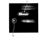
図13は、図10に示す放射線非破壊検査装置1Aで配管2の溶接部にX線Eを照射することにより得られた画像の一例を示す図である。
【0167】
図13に示すように、被検体である配管2の画像がモニタ42に表示される。配管2には欠陥部が自動的に判別されて確認されたため、四角形の枠で欠陥部がマーキング50されている。さらに、配管2の欠陥部の縦方向、横方向、斜方向の寸法と面積とが自動計算されて欠陥部情報ファイル51が作成され、作成された欠陥部情報ファイル51が20020830のようなファイル名とともに配管2の欠陥部の近傍に表示されている。
【0168】
さらに、欠陥部情報ファイル51の表示内容と配管2の欠陥部に設けられたマーキング50が例えばp1というような記号により関連付けられ、欠陥部の位置と大きさの対応が明確化される。
【0169】
このため、配管2に欠陥部が複数箇所ある場合には、欠陥部の位置と大きさの対応が明確となり、より容易に配管2の検査を実施して記録を保存することができる。
【0170】
すなわち、放射線非破壊検査装置1Aは、平面検出器4とX線源3の照射ヘッド5とを多関節アーム44を備えた移動機構40に一体化して固定するとともに、移動機構40を制御することにより遠隔から平面検出器4とX線源3の照射ヘッド5との相対的な位置関係を一定としつつ平面検出器4とX線源3の照射ヘッド5とを容易に位置決めできるように構成したものである。
【0171】
さらに、平面検出器4で得られた被検体の画像を自動的に判定することにより、あるいは画像の判断を支援することにより熟練技術を要することなく、異なる作業者であってもより均一で適切な検査結果を得ることができるように構成したものである。
【0172】
放射線非破壊検査装置1Aでは、遠隔操作により被検体の放射線による非破壊検査が実施できるため、作業者の被曝を低減させることができる。さらに、X線源3から放射されるX線Eのオンオフ操作を遠隔から電源のオンオフ操作により行えるため、X線源3の管理が容易となる。
【0173】
また、放射線非破壊検査装置1Aでは、平面検出器4とX線源3の照射ヘッド5との相対的な位置関係が一定であるため、位置決めがより容易でありかつより正確で適切な強度でXを被検体に照射することができる。このため、より高感度で適切な被検体の画像を得ることができる。
【0174】
さらに、同一の被検査体を複数回検査する場合に、常に平面検出器4とX線源3の照射ヘッド5との相対的な位置条件が一定でるため、互いに比較が容易な検査結果をそれぞれ得ることができる。このため、検査結果の判断が容易となる。
【0175】
また、放射線非破壊検査装置1Aでは、被検体のX線画像を現像することなくデジタル画像情報に変化し、かつ変換したデジタル画像情報の濃淡等の条件から被検体の欠陥部を自動的に判別するため、作業者が欠陥部の有無を判断することなく被検体の欠陥部を検出することが可能となる。
【0176】
一般に配管2を検査する場合には、配管2の差込不足や溶接部の溶け込み不足の有無が検査対象となり、これら検査対象に応じて検査項目や機能の有無を判断する際の欠陥部の大きさ等の基準が異なる。検査対象に応じた判断基準を作業者が記憶することは困難であり、作業者は、検査対象に応じた判断基準を検査ごとに確認する必要があった。
【0177】
さらに、判断基準により作業者が判断するため、作業者によって判断結果にバラツキが生じるのみならず適切な判断基準の選択ミスによる判断ミスが生じる恐れがあった。
【0178】
しかし、放射線非破壊検査装置1Aでは、被検体の欠陥部を自動的にマーキング表示するのみならず欠陥部の大きさを自動計算し、さらに計算した欠陥部の大きさと欠陥部が存在する部位における寸法基準値とを比較することにより被検体の良否を判断するため、専門的な知識や熟練技能を有さない一般の作業者であってもより容易に被検体を検査することができる。
【0179】
そして、被検体の欠陥部の状態を適切に把握してバラツキがなくより均一な被検体の検査結果を自動的に精度よく効率的に得ることができる。
【0180】
また、放射線非破壊検査装置1Aでは、被検体の欠陥部が寸法基準値を満たさない場合には、ランプ47およびブザー48を作動させるため、作業者は被検体に不良部が存在することを確実かつ容易にて知ることができる。
【0181】
また、放射線非破壊検査装置1Aでは、例えば被検体の経年変化を検査するような被検体の時間的な変化を比較することが必要な場合に、前回あるいは最近被検体を検査した際の被検体の画像情報や被検体の使用開始時における未使用状態の画像情報で構成される基準画像情報と撮影で得られた画像情報を比較することができる。このため、作業者は腐食の発生や異物の存在等の変化を容易に確認して被検体が所要の品質および機能を具備しているか否かを判断することができる。
【0182】
さらに、作業者が被検体の画像情報からでは、被検体の品質および機能の判断が困難な場合には、被検体の画像情報や被検体の欠陥部を示す欠陥部情報ファイルを技術者に迅速に送信して、技術者による適切な判断が可能となる。
【0183】
このため工業利用に限らず、医療診断用放射線撮影をはじめとする各種の放射線撮影において検査ミスの発生を抑制し、検査情報をより高精度で多く得ることが可能である。
【0184】
また、X線Eやγ線等の放射線は肉眼でとらえることができないため、十分な被曝回避手段を設ける必要がある。X線源3からX線Eを放射させる場合には、X線源3に電源を入れたときのみX線Eが放射されるが、特にγ線源からγ線を放射させる場合には、一旦γ線がγ線源格納ユニットから放出されると線量計でモニタ42しないとγ線の存在を知ることができない。
【0185】
しかし、放射線非破壊検査装置1Aでは、X線Eが放射されている場合に、ランプ47およびブザー48を作動させるため、作業者は放射線が放射されていることを確実かつ容易に知ることが可能となり、作業者の被曝を容易に回避させることができるのみならず、平面検出器4への強度のX線Eの入射を回避させて平面検出器4のX線Eによる損傷を抑制することができる。
【0186】
尚、放射線非破壊検査装置1Aにおいて、放射線源としてX線源3の代わりにγ線を放射するγ線源を使用し、放射線としてγ線を被検体に照射し、被検体を透過したγ線を検出することにより被検体を検査するように構成してもよい。
【0187】
また、放射線非破壊検査装置1Aにおいて、情報制御サーバ41全体あるいは一部と移動機構40とを一体に構成してもよい。逆に、移動機構40に設けられたX線コントローラ6を、移動機構40とは別々に構成してもよい。
【0188】
また、放射線非破壊検査装置1に情報制御サーバ41を接続する構成としてもよく、さらに情報制御サーバ41を従来の任意の放射線非破壊検査装置1に接続してもよい。
【0189】
また、放射線非破壊検査装置1Aにおいて、放射線照射表示手段41eは、平面検出器4のCMOSセンサ16等の任意の構成あるいは放射線源と連動して放射線が放射されている状態であることを検知するように構成してもよい。
【0190】
また、放射線非破壊検査装置1Aにおいて、欠陥部判定手段41iの動作指令情報を受けるランプ47およびブザー48と、放射線照射表示手段41eから動作指令情報を受けるランプ47およびブザー48とを別々に構成してもよく、さらに必要に応じて任意数箇所設けることができる一方、逆にランプ47およびブザー48を設けなくてもよい。
【0191】
【発明の効果】
本発明に係る放射線非破壊検査装置および放射線非破壊検査方法おいては、X線等の放射線を被検体に照射し、被検体を透過した放射線をより高感度で検出することにより、被検体を破壊することなくより短時間で精度よく非破壊検査をすることができる。
【図面の簡単な説明】
【図1】本発明に係る放射線非破壊検査装置の第1の実施形態を示す構成図。
【図2】図1に示すX線源の詳細構成の一例を示す正面図。
【図3】図2に示すX線コントローラの上面図。
【図4】図2に示すX線コントローラの左側面図。
【図5】図1に示す平面検出器の具体的な寸法および形状の一例を示す正面図。
【図6】図5に示す平面検出器の左側面図。
【図7】放射線を照射する前後における光ファイバに入射した光の波長と光ファイバに入射した光の相対吸収率との関係を示す図。
【図8】CCDセンサの感度とCCDセンサが受光する光の波長との関係を示す図。
【図9】図1に示す放射線非破壊検査装置で配管の溶接部にX線を照射することにより得られた画像の一例を示す図。
【図10】本発明に係る放射線非破壊検査装置の第2の実施形態を示す構成図。
【図11】図10に示す放射線非破壊検査装置の移動機構に接続される情報制御サーバの機能ブロック図。
【図12】図10に示す放射線非破壊検査装置により被検体の検査をする際の流れを示すフローチャート。
【図13】図10に示す放射線非破壊検査装置で配管の溶接部にX線を照射することにより得られた画像の一例を示す図。
【符号の説明】
1、1A 放射線非破壊検査装置
2 配管
3 X線源
4 平面検出器
5 照射ヘッド
6 X線コントローラ
7 X線管
8 フレキシブルガイドホース
9 油冷ホース
10 電源ケーブル
11 油冷循環パイプ
12 遮蔽材
13 電気回路
14 シンチレータ
15 ファイバオプティックプレート
16 CMOSセンサ
17 X線検出面
18 マスク用冶具
19 ペネトラメータ
20 高圧電源
21 冷却ユニット
22 樹脂カバー
23 ポンプ
24 ラジエータ
25 ファン
26 冷却油
30 ペネトラメータの画像
40 移動機構
41 情報制御サーバ
41a 移動機構制御手段
41b 放射線制御手段
41c 画像入力手段
41d 画像出力手段
41e 放射線照射表示手段
41f 欠陥部表示手段
41g 欠陥部寸法算出手段
41h 欠陥部基準値表示手段
41i 欠陥部判定手段
41j 基準画像表示手段
41k 欠陥部情報ファイル編集手段
41l 通信手段
42 モニタ
43 クライアント
44 多関節アーム
45 車輪
46 関節部分
47 ランプ
48 ブザー
50 マーキング
51 欠陥部情報ファイル
E X線
A 相対吸収率曲線
B 相対吸収率曲線
C CCDセンサ感度特性曲線
D CCDセンサ感度特性曲線[0001]
TECHNICAL FIELD OF THE INVENTION
The present invention relates to a radiation non-destructive inspection apparatus and a radiation non-destructive inspection method for irradiating a subject with radiation such as X-rays and detecting radiation transmitted through the subject without destroying the subject.
[0002]
[Prior art]
When radiation such as X-rays and γ-rays pass through a subject, conditions such as the wavelength and amount of radiation absorbed or scattered by the object differ depending on the type of the substance constituting the subject and the shape of the object.
[0003]
For this reason, conventionally, as radiography or non-destructive radiography that measures the internal state without destroying the subject, for example, a method of examining the internal state of the human body by radiography, radiation transmitted through an object The photographed image is recorded on a recording medium such as a photograph, a video tape, a digital file or the like, and the photographed image is determined. There is a method of grasping the shape and quantity of another object.
[0004]
Conventionally, radiation non-destructive inspection devices used for medical diagnosis or industrial non-destructive inspection include radiation sources such as X-ray sources and γ-ray sources and radiation detectors such as X-ray detectors and γ-ray detectors. Is provided with the subject interposed therebetween, and the radiation irradiated on the subject and transmitted therethrough is detected by a radiation detector to obtain a transmission image of the subject.
[0005]
The X-ray detector includes a radiographic intensifying screen and an X-ray film. Then, the X-rays transmitted through the subject are converted into visible light by the X-ray reaction phosphor of the radiographic intensifying screen, and the converted visible light is guided to the X-ray film to blacken silver particles on the X-ray film. By doing so, a transmission image of the subject is obtained.
[0006]
As the X-ray reaction phosphor of the X-ray detector, for example, a material (Gd which contains gadolinium oxysulfide and terbium as an activator) is used. 2 O 2 A green type phosphor such as S: Tb) is used.
[0007]
On the other hand, as another configuration of the X-ray detector, there is a configuration in which a CCD (Chargecoupled device) camera is used instead of the X-ray film. In an X-ray detector using a CCD camera, X-rays transmitted through a subject are converted into visible light in an X-ray reactive phosphor, and the converted visible light is digitally detected as an electrical signal by a photodetector.
[0008]
However, when using a CCD camera, a relatively long distance is required between the lens of the CCD camera and the X-ray reactive phosphor in order to obtain an image of the CCD element. There is a problem that it is difficult to apply in a connection narrow space.
[0009]
Therefore, as a configuration of the flat X-ray detector, a TFT (Thin Film Transistor) element or a CMOS (Complementary Metal Oxide Semiconductor) sensor is provided instead of the CCD camera, and the X-ray reaction phosphor is provided. There is a type in which the visible light converted in the above is converted into an electric signal by a TFT element or a CMOS sensor, or a type in which an amorphous selenium thin film is provided to directly convert X-rays into a current.
[0010]
Here, if X-rays with high energy enter the photodetector, the photodetector may be damaged. Therefore, in an industrial X-ray detector using X-rays with high energy, damage of the photodetector is not affected. A fiber optics plate for absorbing or scattering X-rays is provided between the X-ray reaction phosphor and the photodetector to reduce the amount.
[0011]
However, although the fiber optics plate reduces damage to the photodetector, the visible light converted by the X-ray responsive phosphor is absorbed by the fiber optics plate particularly in a shorter wavelength region than the infrared region. However, there is a problem that the sensitivity of the X-ray detector is reduced.
[0012]
For this reason, for industrial inspection such as piping inspection using a γ-ray source such as iridium having a high energy of 300 to 400 KeV as a radiation source, radiation using a radiation detector composed of a radiation reactive phosphor and an industrial radiation film is used. A radiation transmission test is performed by a nondestructive inspection device.
[0013]
Then, if necessary, the industrial radiographic film obtained by photographing the subject is converted into digital radiography by a scanner and processed.
[0014]
When an industrial X-ray film is used to capture visible light, a penetrameter is simultaneously photographed as an index of the imaging conditions, and an object such as a pipe is inspected using the penetrameter as an index.
[0015]
[Patent Document 1]
JP-A-2002-156456
[0016]
[Patent Document 2]
JP-A-2002-022835
[0017]
[Problems to be solved by the invention]
However, in the conventional industrial radiation nondestructive inspection apparatus, not only after developing the industrial radiation film, it is not only possible to obtain an image of the subject, but also to fail in imaging of the subject In such a case, it is necessary to take an image again, so that it is impossible to inspect the subject in real time or quickly at the time of imaging at the site and judge the quality and function of the object.
[0018]
Also, judgment of an inspection image using an industrial radiation film and a penetrameter requires much experience, and the number of people who can perform the inspection is limited. For this reason, even if the subject is imaged, a long time is required for the determination, and it is not possible to carry out an efficient test of the subject at the site.
[0019]
On the other hand, when the radiation detector is constituted by a light detection element instead of an industrial radiation film, an optical element such as a fiber optics plate for shielding is provided in order to avoid damage to the light detection element from high-energy radiation. Therefore, it takes time to image the subject because the sensitivity of the radiation detector decreases.
[0020]
In addition, when performing non-destructive radiological inspections not only for industrial use but also for medical use, the sensitivity of the radiation detector is low, and the time required for imaging the subject increases the exposure of the patient who is the subject. Since a problem arises, it is important to improve the sensitivity of the radiation detector to shorten the imaging time of the subject.
[0021]
The present invention has been made in order to cope with such a conventional situation, and irradiates a subject with radiation such as X-rays and detects the radiation transmitted through the subject with higher sensitivity to destroy the subject. It is an object of the present invention to provide a radiation non-destructive inspection device and a radiation non-destructive inspection method capable of performing inspection in a shorter time without performing.
[0022]
[Means for Solving the Problems]
In order to achieve the above object, a nondestructive radiation inspection apparatus according to the present invention detects a radiation source that irradiates a subject with radiation and radiation that has passed through the subject, as described in
[0023]
Further, in order to achieve the above object, the nondestructive radiation inspection method according to the present invention includes a step of irradiating the subject with radiation, and a step of receiving the radiation transmitted through the subject. Generating visible light in the red region, transmitting the generated visible light and absorbing the radiation, and receiving the transmitted visible light and converting it into an electric signal to image the subject. Obtaining information.
[0024]
BEST MODE FOR CARRYING OUT THE INVENTION
An embodiment of a radiation nondestructive inspection apparatus and a radiation nondestructive inspection method according to the present invention will be described with reference to the accompanying drawings.
[0025]
FIG. 1 is a configuration diagram showing a first embodiment of the radiation nondestructive inspection apparatus according to the present invention.
[0026]
The radiation
[0027]
The
[0028]
The
[0029]
The
[0030]
The surface of the
[0031]
A
[0032]
The position at which the
[0033]
Further, a penetrator for judging and calibrating the size of a required part of the
[0034]
Next, the detailed configuration and function of the
[0035]
2 is a front view showing an example of a detailed configuration of the
[0036]
The
[0037]
The
[0038]
On the other hand, when the X-ray E is emitted from the
[0039]
The cooling
[0040]
Further, the cooling
[0041]
That is, the
[0042]
On the other hand, the
[0043]
Further, in order to make the arrangement of the
[0044]
In addition, while the
[0045]
That is, in the
[0046]
For this reason, the amount of the lead shield used for the case of the
[0047]
Further, the
[0048]
Next, a specific example of the shape of the
[0049]
FIG. 5 is a front view showing an example of specific dimensions and shapes of the
[0050]
The
[0051]
The
[0052]
The
[0053]
The
[0054]
However, at this time, a part of the X-rays E are transmitted through the
[0055]
The
[0056]
Further, the
[0057]
The
[0058]
When the high-intensity X-rays E are incident on the
[0059]
Therefore, as shown in FIG. 1, the area of the X-ray E irradiated from the
[0060]
Further, even when the X-rays E emitted from the
[0061]
For this reason, the intensity of the X-rays E passing through the subject and reaching the
[0062]
That is, the
[0063]
Further, at this time, when X-rays E are incident on the
[0064]
Here, the X-rays E transmitted through the
[0065]
FIG. 7 is a diagram showing the relationship between the wavelength of light incident on the optical fiber and the relative absorptivity of the light incident on the optical fiber before and after irradiation with radiation.
[0066]
In FIG. 7, the horizontal axis indicates the wavelength of the light incident on the optical fiber, and the vertical axis indicates the relative absorptivity of the light incident on the optical fiber. In FIG. 7, a dashed line indicates a relative absorption curve A of light by the optical fiber before irradiating the optical fiber with radiation, and a solid line indicates a relative absorption curve B of light by the optical fiber after irradiating the optical fiber with radiation. Is shown.
[0067]
According to the curve A of the relative absorptivity of light by the optical fiber before irradiating the optical fiber of FIG. 7, the relative absorptivity of the optical fiber increases as the wavelength of the light becomes shorter. The wavelength also becomes shorter and the light absorption rate increases remarkably as it approaches the ultraviolet region.
[0068]
On the other hand, according to the relative absorptivity curve B of light by the optical fiber after irradiating the optical fiber, the relative absorptivity of the optical fiber increases as the wavelength of the light decreases, but the optical fiber is irradiated with the radiation. It is higher than the relative absorptivity of light by the previous optical fiber. In other words, it can be seen that irradiating the optical fiber with radiation increases the light absorption of the optical fiber and decreases the light transmittance.
[0069]
Further, according to the relative absorptivity curve B of the light after irradiating the optical fiber with the radiation, the relative absorptivity of the light has a maximum value when the wavelength of the light is around 600 nm, and the optical fiber is irradiated with the radiation. It can be seen that the amount of increase in the light absorptivity due to is significant.
[0070]
Furthermore, when the wavelength of light is around 700 nm, the relative absorptivity of light of the optical fiber after irradiating the radiation is not only the minimum value, but also the absorptivity of light by irradiating the optical fiber with the radiation. It can be seen that the amount of increase is significantly smaller than the other light wavelength regions.
[0071]
On the other hand, the sensitivity at which a semiconductor light receiving element such as the
[0072]
FIG. 8 is a diagram illustrating the relationship between the sensitivity of the CCD sensor and the wavelength of light received by the CCD sensor.
[0073]
8, the vertical axis indicates the relative sensitivity of the CCD sensor, and the horizontal axis indicates the wavelength of light received by the CCD sensor. Further, the solid line in FIG. 8 indicates the CCD sensor sensitivity characteristic curve C of the CCD sensor having high sensitivity to light in the red region, and the dashed line indicates the CCD sensor sensitivity characteristic curve D of the CCD sensor having high sensitivity to light in the green region. Show.
[0074]
Each of the CCD sensor sensitivity characteristic curves C and D of each CCD sensor shown in FIG. 8 shows the same tendency, and when the wavelength of light received by the CCD sensor is in the range of about 450 nm to 700 nm, the relative sensitivity Increases and reaches a maximum value or a maximum value, but the maximum value of the relative sensitivity differs from the wavelength of light at that time.
[0075]
That is, from the CCD sensor sensitivity characteristic curve C shown by the solid line, the relative sensitivity of the CCD sensor having high sensitivity to light in the red region becomes the maximum value when light in the red region having a light wavelength of about 650 nm is received. The relative sensitivity of the CCD sensor having high sensitivity to the light in the green region from the CCD sensor sensitivity characteristic curve D indicated by the dashed line may be the maximum value when the light in the green region having a light wavelength of about 500 nm is received. I understand.
[0076]
Furthermore, comparing the maximum values of the CCD sensor sensitivity characteristic curves C and D, the relative sensitivity of the CCD sensor having high sensitivity to light in the red region is higher than the relative sensitivity of the CCD sensor having high sensitivity to light in the green region. Is also good.
[0077]
In addition, for visible light having a wavelength in the range of about 450 nm to about 650 nm, the relative sensitivity of the CCD sensor having high sensitivity to light in the red region is always higher than that of the CCD sensor having high sensitivity to light in the green region. It is larger than the maximum value of sensitivity.
[0078]
Therefore, the sensitivity of the semiconductor light receiving element such as the CCD sensor and the
[0079]
As described above, in the
[0080]
Further, by adding a required amount of an activator such as an element of the lanthanoid element series, for example, europium (Eu) element, to the red type phosphor, the wavelength of light generated from the phosphor is adjusted, and the light in the
[0081]
If europium (Eu) is added to the phosphor as an activator, the crystal field of the phosphor can be excited at the excitation level of the forbidden transition when the activator is not added. For example, in a phosphor to which europium (Eu) is added, light having a wavelength shown in Formulas (1) and (2) can be emitted by excitation shown in Formulas (1) and (2).
[0082]
(Equation 1)
On the other hand, as the semiconductor light receiving element, there is a photoelectric conversion element such as a CCD sensor, a
[0084]
Therefore, in order to correspond to the sensitivity characteristics of a semiconductor light receiving element having sensitivity in each wavelength region of light, the amount of a green component or a blue component is adjusted by adjusting the concentration of an activator added to a red type phosphor. Can be.
[0085]
Examples of the activator to be added to the red-type phosphor include lanthanide such as terbium (Tb) or praseodymium (Pr), which can emit light containing a green component as a main component, in addition to europium (Eu). Element.
[0086]
Next, the operation of the non-destructive
[0087]
The
[0088]
On the other hand, the
[0089]
In the vicinity of the
[0090]
Further, a
[0091]
Next, power is applied to the
[0092]
On the other hand, the cooling
[0093]
Further, the X-ray E emitted from the
[0094]
The
[0095]
When the
[0096]
At this time, when the
[0097]
When the
[0098]
Further, the
[0099]
As a result, it is possible to obtain an image of the internal structure of the
[0100]
Next, an example of an image obtained by the radiation
[0101]
FIG. 9 is a diagram illustrating an example of an image obtained by irradiating the welded portion of the
[0102]
As shown in FIG. 9, an image obtained by converting the X-ray E transmitted through the
[0103]
Further, in FIG. 9, an
[0104]
For this reason, it is possible to obtain a result that the size of a portion of the welded portion of the
[0105]
That is, the radiation
[0106]
Further, in order to easily irradiate the subject with the X-rays E even if the subject is disposed in a narrow portion such as the
[0107]
In the non-destructive
[0108]
Further, in the non-destructive
[0109]
For this reason, especially in the case of a medical destructive inspection, it is possible to reduce the exposure dose of the patient who is the subject.
[0110]
On the other hand, in the case of industrial destructive inspection, conventionally, nondestructive inspection is performed by a method of receiving visible light with an X-ray film and developing X-rays E radiated from a radiation source to a subject and transmitted therethrough. Therefore, it took a long time to develop and dry the X-ray film, and it was impossible to obtain an inspection result in real time. Furthermore, when the X-ray imaging of the subject fails, it is necessary to take another image, which increases the examination time and labor.
[0111]
However, since the radiation
[0112]
Further, in the radiation
[0113]
In addition, in the non-destructive
[0114]
FIG. 10 is a configuration diagram showing a second embodiment of the radiation nondestructive inspection apparatus according to the present invention.
[0115]
In the nondestructive
[0116]
The nondestructive
[0117]
The relative positional relationship between the
[0118]
Further, the
[0119]
An
[0120]
On the other hand, a
[0121]
Further, between the
[0122]
FIG. 11 is a functional block diagram of the
[0123]
The
[0124]
The moving mechanism control means 41a of the
[0125]
The
[0126]
The
[0127]
The
[0128]
Further, an arbitrary number of
[0129]
The radiation irradiation display means 41e of the
[0130]
The
[0131]
That is, in order to prevent the worker from being exposed, the worker can know that the X-ray E is being emitted from the
[0132]
Further, upon receiving the image information of the subject from the image input means 41c, the defective part display means 41f of the
[0133]
As a method of determining the defective portion of the subject by the defective portion display means 41f, for example, a method of quantifying the density of the image information and comparing it with a predetermined reference value to determine the presence or absence and the range of the defective portion is provided.
[0134]
Further, the defective portion display means 41f has a function of providing a defective portion information file to the defective portion size calculating means 41g together with image information of the subject when a defective portion exists in the subject.
[0135]
Upon receiving the image information and the defect information file of the subject from the defect display means 41f, the defect size calculating means 41g of the
[0136]
The defect reference value display means 41h of the
[0137]
For this reason, the operator compares the dimensional information of the defect portion of the subject in the defect portion information file displayed on the
[0138]
The defective part determination unit 41i of the
[0139]
The
[0140]
In the reference image display means 41j of the
[0141]
The reference image information of the subject is used as image information of the subject at the time of the previous or recent examination of the subject or image information of an unused state at the start of use of the subject. This makes it easy to determine when the quality or function of the device deteriorates.
[0142]
That is, the reference image information is arbitrary as long as the image information is a comparison target of the image information obtained by the imaging with the X-ray E.
[0143]
For this reason, the worker compares the image information, which is a photographing result of the examination of the subject displayed on the
[0144]
The defective part information file editing means 41k of the
[0145]
The communication unit 41l of the
[0146]
Next, the operation of the nondestructive
[0147]
FIG. 12 is a flowchart showing a flow when the subject is inspected by the non-destructive
[0148]
First, in step S1, the control information is input from the
[0149]
Furthermore, a
[0150]
In addition, between the
[0151]
Next, in step S2, the control information is input from the
[0152]
Therefore, in step S3, the X-rays E transmitted through the
[0153]
Then, in step S4, the
[0154]
Further, in step S5, the
[0155]
Further, in step S6, the defective portion display means 41f automatically determines the defective portion of the
[0156]
For this reason, the worker can easily confirm the defective portion of the
[0157]
Then, in step S7, the defective part
[0158]
Further, in step S8, the defective part reference value display means 41h determines whether or not the defective part exists in the
[0159]
For this reason, the operator checks the size of the defective portion of the
[0160]
In step S9, the defective portion determination unit 41i compares the size of the defective portion of the
[0161]
For this reason, the operator can easily know that the defective portion of the
[0162]
On the other hand, in step S10, for example, the secular change of the
[0163]
For this reason, the worker compares the image information, which is the photographing result of the
[0164]
Further, in step S11, if it is difficult for the operator to determine the quality and function of the
[0165]
For this reason, the technician of the
[0166]
FIG. 13 is a diagram illustrating an example of an image obtained by irradiating the welded portion of the
[0167]
As shown in FIG. 13, an image of the
[0168]
Further, the display content of the defective
[0169]
For this reason, when there are a plurality of defective portions in the
[0170]
That is, the radiation
[0171]
Further, by automatically judging the image of the subject obtained by the
[0172]
In the radiation
[0173]
In the nondestructive
[0174]
Further, when the same object is inspected a plurality of times, since the relative position condition between the
[0175]
Further, in the nondestructive
[0176]
In general, when inspecting the
[0177]
Furthermore, since the operator makes a judgment based on the judgment criteria, there is a possibility that not only the judgment results vary from one operator to another, but also a judgment error due to a mistake in selecting an appropriate judgment standard.
[0178]
However, the nondestructive
[0179]
Then, the state of the defective portion of the subject can be appropriately grasped, and a more uniform test result of the subject without variation can be obtained automatically, accurately and efficiently.
[0180]
Further, in the nondestructive
[0181]
Further, in the nondestructive
[0182]
Furthermore, if it is difficult for the operator to determine the quality and function of the subject from the image information of the subject, the operator can quickly send the image information of the subject and a defect information file indicating the defect of the subject to a technician. And the technician can make an appropriate decision.
[0183]
For this reason, it is possible to suppress the occurrence of inspection errors in various types of radiography including medical diagnostic radiography, not limited to industrial use, and to obtain more test information with higher accuracy.
[0184]
In addition, since radiation such as X-rays E and γ-rays cannot be detected with the naked eye, it is necessary to provide a sufficient means for avoiding exposure. When the
[0185]
However, in the non-destructive
[0186]
In the radiation
[0187]
Further, in the radiation
[0188]
Further, the
[0189]
In the radiation
[0190]
In the nondestructive
[0191]
【The invention's effect】
In the radiation non-destructive inspection apparatus and the radiation non-destructive inspection method according to the present invention, by irradiating the subject with radiation such as X-rays, and detecting the radiation transmitted through the subject with higher sensitivity, Non-destructive inspection can be performed accurately in a shorter time without breaking.
[Brief description of the drawings]
FIG. 1 is a configuration diagram showing a first embodiment of a non-destructive radiation inspection apparatus according to the present invention.
FIG. 2 is a front view showing an example of a detailed configuration of the X-ray source shown in FIG.
FIG. 3 is a top view of the X-ray controller shown in FIG. 2;
FIG. 4 is a left side view of the X-ray controller shown in FIG. 2;
FIG. 5 is a front view showing an example of specific dimensions and shapes of the flat panel detector shown in FIG. 1;
FIG. 6 is a left side view of the flat panel detector shown in FIG. 5;
FIG. 7 is a diagram showing a relationship between a wavelength of light incident on an optical fiber and a relative absorptivity of light incident on the optical fiber before and after irradiation with radiation.
FIG. 8 is a diagram showing the relationship between the sensitivity of a CCD sensor and the wavelength of light received by the CCD sensor.
9 is a view showing an example of an image obtained by irradiating a welded portion of a pipe with X-rays by the radiation nondestructive inspection apparatus shown in FIG. 1;
FIG. 10 is a configuration diagram showing a second embodiment of the radiation nondestructive inspection apparatus according to the present invention.
FIG. 11 is a functional block diagram of an information control server connected to the moving mechanism of the radiation nondestructive inspection apparatus shown in FIG.
FIG. 12 is a flowchart showing a flow when an object is inspected by the nondestructive radiation inspection apparatus shown in FIG. 10;
13 is a view showing an example of an image obtained by irradiating a welded part of a pipe with X-rays by the radiation nondestructive inspection apparatus shown in FIG.
[Explanation of symbols]
1, 1A Non-destructive radiation inspection equipment
2 Piping
3 X-ray source
4 Flat panel detector
5 Irradiation head
6 X-ray controller
7 X-ray tube
8 Flexible guide hose
9 Oil-cooled hose
10 Power cable
11 Oil-cooled circulation pipe
12 Shielding material
13 Electric circuit
14 scintillator
15 Fiber optic plate
16 CMOS sensor
17 X-ray detection surface
18 Jig for mask
19 Penetrator
20 High voltage power supply
21 Cooling unit
22 Resin cover
23 pump
24 radiators
25 fans
26 Cooling oil
Image of 30 penetrameter
40 Moving mechanism
41 Information Control Server
41a Moving mechanism control means
41b radiation control means
41c Image input means
41d image output means
41e Radiation irradiation display means
41f defective part display means
41g Defect portion size calculation means
41h Defect part reference value display means
41i Defective part determining means
41j Reference image display means
41k Defect part information file editing means
41l communication means
42 monitor
43 Client
44 Articulated arm
45 wheels
46 Joints
47 lamp
48 Buzzer
50 Marking
51 Defect information file
EX-ray
A Relative absorption rate curve
B relative absorption rate curve
C CCD sensor sensitivity characteristic curve
DC CCD sensor sensitivity characteristic curve
Claims (15)
Priority Applications (1)
| Application Number | Priority Date | Filing Date | Title |
|---|---|---|---|
| JP2003028454A JP4127795B2 (en) | 2003-02-05 | 2003-02-05 | Radiation nondestructive inspection equipment |
Applications Claiming Priority (1)
| Application Number | Priority Date | Filing Date | Title |
|---|---|---|---|
| JP2003028454A JP4127795B2 (en) | 2003-02-05 | 2003-02-05 | Radiation nondestructive inspection equipment |
Publications (2)
| Publication Number | Publication Date |
|---|---|
| JP2004239731A true JP2004239731A (en) | 2004-08-26 |
| JP4127795B2 JP4127795B2 (en) | 2008-07-30 |
Family
ID=32955923
Family Applications (1)
| Application Number | Title | Priority Date | Filing Date |
|---|---|---|---|
| JP2003028454A Expired - Fee Related JP4127795B2 (en) | 2003-02-05 | 2003-02-05 | Radiation nondestructive inspection equipment |
Country Status (1)
| Country | Link |
|---|---|
| JP (1) | JP4127795B2 (en) |
Cited By (7)
| Publication number | Priority date | Publication date | Assignee | Title |
|---|---|---|---|---|
| JP2008268103A (en) * | 2007-04-24 | 2008-11-06 | Toshiba Corp | Thickness measuring device and method for measuring thickness |
| JP2009186271A (en) * | 2008-02-05 | 2009-08-20 | Shimadzu Corp | X-ray inspection apparatus |
| JP2009186270A (en) * | 2008-02-05 | 2009-08-20 | Shimadzu Corp | X-ray inspection device |
| KR101223229B1 (en) | 2012-07-09 | 2013-01-17 | 유영검사 주식회사 | An apparatus managing exposure of radiation source for a nondestructive inspection apparatus |
| US9136029B2 (en) | 2010-06-04 | 2015-09-15 | Hamamatsu Photonics K.K. | Scintillator panel, and radiographic image sensor |
| CN118067750A (en) * | 2024-04-19 | 2024-05-24 | 四川赛康智能科技股份有限公司 | X-ray detection device and method for strain clamp of four-split conductor of power transmission line |
| WO2024210241A1 (en) * | 2023-04-07 | 2024-10-10 | 엘지전자 주식회사 | X-ray detector for non-destructive inspection |
-
2003
- 2003-02-05 JP JP2003028454A patent/JP4127795B2/en not_active Expired - Fee Related
Cited By (7)
| Publication number | Priority date | Publication date | Assignee | Title |
|---|---|---|---|---|
| JP2008268103A (en) * | 2007-04-24 | 2008-11-06 | Toshiba Corp | Thickness measuring device and method for measuring thickness |
| JP2009186271A (en) * | 2008-02-05 | 2009-08-20 | Shimadzu Corp | X-ray inspection apparatus |
| JP2009186270A (en) * | 2008-02-05 | 2009-08-20 | Shimadzu Corp | X-ray inspection device |
| US9136029B2 (en) | 2010-06-04 | 2015-09-15 | Hamamatsu Photonics K.K. | Scintillator panel, and radiographic image sensor |
| KR101223229B1 (en) | 2012-07-09 | 2013-01-17 | 유영검사 주식회사 | An apparatus managing exposure of radiation source for a nondestructive inspection apparatus |
| WO2024210241A1 (en) * | 2023-04-07 | 2024-10-10 | 엘지전자 주식회사 | X-ray detector for non-destructive inspection |
| CN118067750A (en) * | 2024-04-19 | 2024-05-24 | 四川赛康智能科技股份有限公司 | X-ray detection device and method for strain clamp of four-split conductor of power transmission line |
Also Published As
| Publication number | Publication date |
|---|---|
| JP4127795B2 (en) | 2008-07-30 |
Similar Documents
| Publication | Publication Date | Title |
|---|---|---|
| US5150394A (en) | Dual-energy system for quantitative radiographic imaging | |
| US7869569B2 (en) | System for quantitative radiographic imaging | |
| US6313465B1 (en) | Radiation discriminative measuring apparatus and radiation discriminative measuring method | |
| JP3554129B2 (en) | Radiography equipment | |
| KR100975417B1 (en) | Digital radiographic inspection system and method | |
| US9500600B2 (en) | Radiation image acquisition system | |
| JP2008268076A (en) | Non-destructive discrimination method, and device | |
| CN107271466B (en) | Nondestructive testing system | |
| JP2008256603A (en) | Nondestructive inspection device and non-destructive inspection method | |
| WO2021201211A1 (en) | Inspection device | |
| JP4127795B2 (en) | Radiation nondestructive inspection equipment | |
| JP2005528598A (en) | Ionizing beam inspection equipment and process | |
| JP2007327967A (en) | Radiation discrimination measuring device | |
| WO2004023159A1 (en) | Dose distribution reading method for glass dosimeter and its apparatus | |
| Gopal et al. | Validity of the line‐pair bar‐pattern method in the measurement of the modulation transfer function (MTF) in megavoltage imaging | |
| KR20080104878A (en) | Radiation exposure time automatic decision system and method for radiograpic testing | |
| JP2006329905A (en) | Line sensor, line sensor unit, and radiation nondestructive inspection system | |
| KR20100033754A (en) | Radiography image acuqisition techinique for boiler tube weldments | |
| US20080035859A1 (en) | Photo-stimulable phosphor imaging plate | |
| JP4836746B2 (en) | Radiation inspection equipment | |
| JP2004208749A (en) | Radiation image photographing device | |
| KR100923624B1 (en) | Radiation transmission image apparatus using CMOS sensors | |
| KR100994794B1 (en) | A radiation detection module for digital radiography | |
| CN110192435A (en) | Detector strip for X-ray film | |
| JP2008268075A (en) | Non-destructive inspection method, and non-destructive inspection device |
Legal Events
| Date | Code | Title | Description |
|---|---|---|---|
| A621 | Written request for application examination |
Free format text: JAPANESE INTERMEDIATE CODE: A621 Effective date: 20050620 |
|
| A977 | Report on retrieval |
Free format text: JAPANESE INTERMEDIATE CODE: A971007 Effective date: 20070216 |
|
| A131 | Notification of reasons for refusal |
Free format text: JAPANESE INTERMEDIATE CODE: A131 Effective date: 20070313 |
|
| A521 | Request for written amendment filed |
Free format text: JAPANESE INTERMEDIATE CODE: A523 Effective date: 20070511 |
|
| A131 | Notification of reasons for refusal |
Free format text: JAPANESE INTERMEDIATE CODE: A131 Effective date: 20071225 |
|
| A521 | Request for written amendment filed |
Free format text: JAPANESE INTERMEDIATE CODE: A523 Effective date: 20080225 |
|
| TRDD | Decision of grant or rejection written | ||
| A01 | Written decision to grant a patent or to grant a registration (utility model) |
Free format text: JAPANESE INTERMEDIATE CODE: A01 Effective date: 20080507 |
|
| A01 | Written decision to grant a patent or to grant a registration (utility model) |
Free format text: JAPANESE INTERMEDIATE CODE: A01 |
|
| A61 | First payment of annual fees (during grant procedure) |
Free format text: JAPANESE INTERMEDIATE CODE: A61 Effective date: 20080512 |
|
| FPAY | Renewal fee payment (event date is renewal date of database) |
Free format text: PAYMENT UNTIL: 20110523 Year of fee payment: 3 |
|
| FPAY | Renewal fee payment (event date is renewal date of database) |
Free format text: PAYMENT UNTIL: 20110523 Year of fee payment: 3 |
|
| FPAY | Renewal fee payment (event date is renewal date of database) |
Free format text: PAYMENT UNTIL: 20110523 Year of fee payment: 3 |
|
| FPAY | Renewal fee payment (event date is renewal date of database) |
Free format text: PAYMENT UNTIL: 20120523 Year of fee payment: 4 |
|
| FPAY | Renewal fee payment (event date is renewal date of database) |
Free format text: PAYMENT UNTIL: 20120523 Year of fee payment: 4 |
|
| FPAY | Renewal fee payment (event date is renewal date of database) |
Free format text: PAYMENT UNTIL: 20130523 Year of fee payment: 5 |
|
| FPAY | Renewal fee payment (event date is renewal date of database) |
Free format text: PAYMENT UNTIL: 20130523 Year of fee payment: 5 |
|
| FPAY | Renewal fee payment (event date is renewal date of database) |
Free format text: PAYMENT UNTIL: 20140523 Year of fee payment: 6 |
|
| LAPS | Cancellation because of no payment of annual fees |