JP2004237784A - Folding type baby carriage - Google Patents
Folding type baby carriage Download PDFInfo
- Publication number
- JP2004237784A JP2004237784A JP2003026602A JP2003026602A JP2004237784A JP 2004237784 A JP2004237784 A JP 2004237784A JP 2003026602 A JP2003026602 A JP 2003026602A JP 2003026602 A JP2003026602 A JP 2003026602A JP 2004237784 A JP2004237784 A JP 2004237784A
- Authority
- JP
- Japan
- Prior art keywords
- seat
- pair
- support side
- baby carriage
- seating surface
- Prior art date
- Legal status (The legal status is an assumption and is not a legal conclusion. Google has not performed a legal analysis and makes no representation as to the accuracy of the status listed.)
- Granted
Links
- 238000005452 bending Methods 0.000 claims abstract description 13
- 239000011162 core material Substances 0.000 claims description 31
- 210000001364 upper extremity Anatomy 0.000 description 10
- 239000004744 fabric Substances 0.000 description 2
- 239000000463 material Substances 0.000 description 1
- 238000012986 modification Methods 0.000 description 1
- 230000004048 modification Effects 0.000 description 1
- 230000000630 rising effect Effects 0.000 description 1
- 210000002784 stomach Anatomy 0.000 description 1
Images


Classifications
-
- B—PERFORMING OPERATIONS; TRANSPORTING
- B62—LAND VEHICLES FOR TRAVELLING OTHERWISE THAN ON RAILS
- B62B—HAND-PROPELLED VEHICLES, e.g. HAND CARTS OR PERAMBULATORS; SLEDGES
- B62B7/00—Carriages for children; Perambulators, e.g. dolls' perambulators
- B62B7/04—Carriages for children; Perambulators, e.g. dolls' perambulators having more than one wheel axis; Steering devices therefor
- B62B7/06—Carriages for children; Perambulators, e.g. dolls' perambulators having more than one wheel axis; Steering devices therefor collapsible or foldable
- B62B7/08—Carriages for children; Perambulators, e.g. dolls' perambulators having more than one wheel axis; Steering devices therefor collapsible or foldable in the direction of, or at right angles to, the wheel axis
-
- A—HUMAN NECESSITIES
- A45—HAND OR TRAVELLING ARTICLES
- A45B—WALKING STICKS; UMBRELLAS; LADIES' OR LIKE FANS
- A45B25/00—Details of umbrellas
- A45B25/28—Drip receptacles for umbrellas; Attaching devices therefor
-
- A—HUMAN NECESSITIES
- A45—HAND OR TRAVELLING ARTICLES
- A45B—WALKING STICKS; UMBRELLAS; LADIES' OR LIKE FANS
- A45B9/00—Details
- A45B9/04—Ferrules or tips
-
- B—PERFORMING OPERATIONS; TRANSPORTING
- B62—LAND VEHICLES FOR TRAVELLING OTHERWISE THAN ON RAILS
- B62B—HAND-PROPELLED VEHICLES, e.g. HAND CARTS OR PERAMBULATORS; SLEDGES
- B62B2205/00—Hand-propelled vehicles or sledges being foldable or dismountable when not in use
- B62B2205/20—Catches; Locking or releasing an articulation
- B62B2205/22—Catches; Locking or releasing an articulation remotely controlled, e.g. from the handlebar
-
- B—PERFORMING OPERATIONS; TRANSPORTING
- B62—LAND VEHICLES FOR TRAVELLING OTHERWISE THAN ON RAILS
- B62B—HAND-PROPELLED VEHICLES, e.g. HAND CARTS OR PERAMBULATORS; SLEDGES
- B62B7/00—Carriages for children; Perambulators, e.g. dolls' perambulators
- B62B7/04—Carriages for children; Perambulators, e.g. dolls' perambulators having more than one wheel axis; Steering devices therefor
- B62B7/06—Carriages for children; Perambulators, e.g. dolls' perambulators having more than one wheel axis; Steering devices therefor collapsible or foldable
- B62B7/08—Carriages for children; Perambulators, e.g. dolls' perambulators having more than one wheel axis; Steering devices therefor collapsible or foldable in the direction of, or at right angles to, the wheel axis
- B62B7/086—Carriages for children; Perambulators, e.g. dolls' perambulators having more than one wheel axis; Steering devices therefor collapsible or foldable in the direction of, or at right angles to, the wheel axis becoming smaller in all three dimensions
Landscapes
- Engineering & Computer Science (AREA)
- Chemical & Material Sciences (AREA)
- Combustion & Propulsion (AREA)
- Transportation (AREA)
- Mechanical Engineering (AREA)
- Carriages For Children, Sleds, And Other Hand-Operated Vehicles (AREA)
- Seats For Vehicles (AREA)
Abstract
Description
【0001】
【発明の属する技術分野】
この発明は、幅方向寸法が縮小するように折畳まれる折畳式乳母車に関し、特に座面後部の落ち込みを防止した折畳式乳母車に関するものである。
【0002】
【従来の技術】
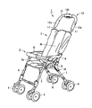
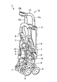
図1および図2は、特開平8−58599号公報に開示された乳母車を示している。図1は乳母車の開状態を示し、図2は乳母車の折畳み状態を示している。図1および図2を比較すれば明らかなように、乳母車1は、4個の車輪4,6が前後および左右に近づくように折畳まれる。
【0003】
図示する乳母車1は、主に棒状の部材で構成された車体2と、この車体2に取付けられて座席を形成する座席ハンモック3とを備える。乳母車車体2は、前輪4を有する1対の前脚5と、後輪6を有する1対の後脚7と、座面の両側部上方に位置する1対の手摺部材8と、各後脚7に回動可能に取付けられた1対の反転部材9と、1対の手摺部材8の後端部分に連結されて上方に延びている逆U字状の形状を有する押棒10とを備える。
【0004】
押棒10は、平行な関係で上下方向に直線的に延びている1対の側部縦棒11と、1対の側部縦棒11の上方端を接続する上部連結部材12とを有する。上部連結部材12は、側部縦棒11を受け入れ、かつこの側部縦棒11の周りを回転し得るようにされた1対の回転部材12aと、1対の回転部材12a間を連結する中央部材12bとを有する。各回転部材12aと中央部材12bとは、図2に示すように折れ曲がり可能に連結されている。
【0005】
4個の車輪4,6上に位置して座席の座面部を形成する下部フレーム構造は、4個の車輪4,6とともに前後および左右に近づくように折畳まれる。座面部の両側部から上方に立ち上がって延びている逆U字形状の押棒10は、図2に示す折畳み状態においては、中央部材12bを前方に突き出して前方に折れ曲がることによって幅方向の寸法を縮小している。
【0006】
座席ハンモック3は、座部3aと、背もたれ部3bとを有する。通常、座席ハンモック3は、布製の縫製生地によって作られ、内部に芯材を有している。
【0007】
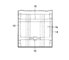
図3は、座席ハンモックの3の座部3aを上方から見た図である。乳母車の車体2は、座席ハンモック3の座部3aを下から支持するために座部下面の両側部において前後方向に延びる1対の座面支持サイド棒13,14を備える。乳母車1の折畳み動作に伴い、1対の座面支持サイド棒13,14は、互いに近づく。
【0008】
上記の折畳み動作を可能にするために、1対の座面支持サイド棒13,14の前方部分は、屈曲リンク部材15によって連結され、後方部分は柔軟なベルト16によって連結されている。屈曲リンク部材15は、乳母車1の開状態においては直線状態を取り、座部3aの前方部分を下から支持する。一方、乳母車1の折畳み状態においては、屈曲リンク部材15は、上方へ屈曲した状態となり、1対の座面支持サイド棒13,14を近づける。
【0009】
ベルト16は、乳母車1の開状態においては、1対の座面支持サイド棒13,14に引っ張られてぴんと張った状態になり、座部3a後方部分を下から支持する。一方、乳母車1の折畳み状態においては1対の座面支持サイド棒13,14が互いに近づくので、ベルト16は弛んだ状態となる。
【0010】
【特許文献1】
特開平8−58599号公報
【0011】
【発明が解決しようとする課題】
特開平8−58599号公報に開示された乳母車では、座席ハンモック3の座部3aの後方部分を柔軟なベルト16によって下から支持している。子供が座席に着座し座部3aの後方部分に体重がかけられると、その重みによりベルト16は下方に湾曲してしまう。
【0012】
そのため、乳母車の使用中、座部3aの後方部分の下方への落ち込みが生じる。その結果、子供の姿勢が適正に保たれず、脊椎が不自然に曲がったり、お腹を圧迫するようなおそれが出てくる。
【0013】
この発明の目的は、幅方向寸法が縮小するように折畳まれる乳母車において、開状態における乳母車の座面を安定に支持し、子供の着座姿勢を適正に保つことのできる折畳式乳母車を提供することである。
【0014】
【課題を解決するための手段】
この発明に従った折畳式乳母車は、幅方向寸法が縮小するように折畳まれるものであって、座面を下から支持するために座面の両側部において前後方向に延びる1対の座面支持サイド棒を備える。各座面支持サイド棒は、座面を下から支え得るように内側方に向かって張り出した剛性のある内方張出部を有する。
【0015】
剛性のある内方張出部は座面を下から安定して支持するので、座面の下方への落ち込みが無く、子供の着座姿勢を適正に保つことができる。特に座面後部の落ち込みを防止する観点から、好ましくは、内方張出部は、座面支持サイド棒の後方部分から内側方に向かって延びている。
【0016】
好ましくは、各座面支持サイド棒は、内方張出部を一体に有する。座面支持サイド棒と内方張出部とを別部材で構成することは可能であるが、その場合であっても両者を一体化すれば剛性が高まるので、座面を安定に支えることができる。
【0017】
一つの実施形態では、内方張出部は、座面支持サイド棒の後方端部分を内側方に向かってU字状に折り曲げることによって形成されている。このような形状の座面支持サイド棒であれば、非常に簡単な機構で座面を安定に支えることができる。
【0018】
具体的な形態の一例として、乳母車は、後輪を有する後脚と、後脚に連結ピンを介して回動可能に連結され、開状態においては連結ピンの上方で後脚に沿い、折畳み状態においては連結ピンの下方で後脚に沿う反転部材と、反転部材に回動可能に連結された連結部材とを備える。好ましくは、座面支持サイド棒と連結部材とは固定されており、座面支持サイド棒のうち、連結部材を超えて後方に延びている部分がU字状に折り曲げられている。
【0019】
好ましくは、乳母車の開状態における左右に位置する1対の内方張出部の間隔は、折畳み動作に伴って1対の座面支持サイド棒が互いに近づく距離に相当する寸法を有する。このような寸法関係であれば、折畳み動作に支障を来たさない。
【0020】
一つの実施形態では、乳母車は、座面を形成する板状の座面芯材を備える。この座面芯材は、好ましくは、1対の座面支持サイド棒に連結されている。このような構成であれば、座面芯材の位置が固定され、なおかつ内方張出部によって下方から安定に支えられるので、座面の位置を確実に安定することができる。この場合、座面芯材は、好ましくは、1対の座面支持サイド棒の内方張出部に連結される。
【0021】
上記の場合、座面芯材と、1対の座面支持サイド棒とは、例えば、ベルトを介して連結されている。また、好ましくは、乳母車は、1対の座面支持サイド棒の前方部分間を連結する屈曲リンク部材を備える。この屈曲リンク部材は、屈曲可能に設けられた中央リンク棒と、1対のサイドリンク棒とを有する。座面芯材は、好ましくは、中央リンク棒に連結されている。
【0022】
【発明の実施の形態】
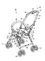
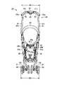
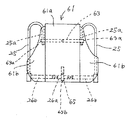
図面を参照して、この発明の一実施形態を説明する。図4は乳母車20の斜視図、図5は折畳み状態の背面図である。
【0023】
図示する乳母車20は、4個の車輪21,22が前後および左右に近づくように折畳まれるものである。乳母車20は、基本的なフレーム構造として、前輪21を有する1対の前脚23と、後輪22を有する1対の後脚24と、座面を下から支えるために座面の両側部において前後方向に延びている1対の座面支持サイド棒25と、座面の両側部上方に位置する1対の手摺部材29と、座面部の両側部から上方に立ち上がって延びている逆U字形状の押棒40と、1対の前脚23間に渡される前脚連結部材27と、1対の後脚24間に渡される後脚連結部材28と、1対の手摺部材29間に渡される前ガード部材30と、1対の座面支持サイド棒25の前方端部間に渡される屈曲リンク部材26とを備える。
【0024】
乳母車20の折畳み動作を実現するために、前脚23の上端部および後脚24の上端部は、それぞれ、手摺部材29に回動可能に連結される。折畳み時には、前後の車輪21,22が互いに近づく。
【0025】
座面支持サイド棒25の前方端部分は前脚23に回動可能に連結され、後方端部分は連結部材32および連結軸46(図6〜図8)を介して反転部材31に回動可能に連結される。
【0026】
逆U字形状の押棒40は、座面部の両側部から上方に立ち上がって延びる1対の側部縦棒41と、この1対の側部縦棒41間を連結する中間棒43とを備える。各側部縦棒41の上部には、カバー部材42が取り付けられている。手摺部材29の後方端部分は、連結軸47を介して側部縦棒41に回動可能に連結される。後に詳しく説明するが、側部縦棒41の下方端部は、連結軸46を介して反転部材31に回動可能に連結される。図4および図5に示すように、1対の側部縦棒41間には、座席ハンモックの背もたれ部(図示省略)を背後から支える背面ベルト33が渡されている。
【0027】
折畳み時に左右の車輪が近づき幅方向寸法が縮小できるようにするために、1対の座面支持サイド棒25間を連結している屈曲リンク部材26は、上方に向かって屈曲可能に設けられている。具体的には、図4および図5に示すように、屈曲リンク部材26は、屈曲可能に連結された中央リンク棒26aと1対のサイドリンク棒26bとを有し、各サイドリンク棒26bの外方端部は座面支持サイド棒25上で回転できるようにされている。
【0028】
1対の後脚24間を連結している後脚連結部材28、および1対の前脚23間を連結している前脚連結部材27も、屈曲リンク部材26と同様に、屈曲可能に設けられている。1対の手摺部材29間を連結している前ガード部材30は、折畳み動作に伴って左右の端部を近づけることができるように柔軟な材料で形成されている。
【0029】
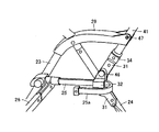
図6〜図8を参照して、押棒40の側部縦棒41と、後脚24と、座面支持サイド棒25との連結構造を説明する。併せて、座面支持サイド棒25の形状を説明する。図6は、乳母車の開状態を示し、図7は折畳み動作の途中状態を示し、図8は折畳み状態を示している。
【0030】
座面支持サイド棒25の後方端部には連結部材32が固定されている。図6から明らかなように、座面支持サイド棒25は、その後方部分に、内側方に向かって張り出した内方張出部25aを一体に有している。具体的には、連結部材32を超えて後方に延びている部分をU字状に折り曲げて内方張出部25a形成している。この内方張出部25aは、座面を下から支えるものである。座面の後方部が、剛性のある座面支持サイド棒25の内方張出部25aによって安定に支持されるので、座面後方部の落ち込みが無く、乳母車の座席に着座した子供の姿勢を適正に保つことができる。乳母車の折畳み動作に伴って1対の座面支持サイド棒25の内方張出部25aは互いに近づく。この折畳み動作に支障を来たさないようにし、なおかつ折畳み状態の幅寸法をできるだけ小さくするために、左右の内方張出部25aの間隔を適正に選ぶ必要がある。具体的には、乳母車の開状態における左右に位置する1対の内方張出部25aの間隔は、折りたたみ動作に伴って1対の座面支持サイド棒25が互いに近づく距離に相当する寸法を有する。したがって、図5に示すように、乳母車の折畳み状態においては、左右の内方張出部25aが密接するようになる。
【0031】
各後脚24には、反転部材31が連結ピンを介して回動可能に取り付けられている。図6に示す乳母車の開状態においては、反転部材31は連結ピンの上方で後脚24に沿うように位置し、図8に示す乳母車の折畳み状態においては、反転部材31は連結ピンの下方で後脚24に沿うように位置する。
【0032】
押棒40の各側部縦棒41の下方端部は、連結軸46を介して反転部材31の先端部分に回動可能に連結される。図6〜図8を比較すれば明らかなように、連結軸46は、座面支持サイド棒25の後方端部と、反転部材31の先端部と、側部縦棒41の下方端部とを、回動可能に連結している。
【0033】
押棒40の側部縦棒41の下方端部分には、上下方向にスライドし得るスライド部材34が設けられている。このスライド部材34は、押棒40内を通るワイヤを介して押棒40の中間棒43に設けられた操作ボタン45(図4参照)に動作可能に連結される。操作ボタン45を操作すれば、スライド部材34を上方に移動させることができる。また、図示していないが、スライド部材34には、ばねによって常に下向きの付勢力が作用している。
【0034】
図6に示す乳母車の開状態では、スライド部材34が反転部材31に係合してこの反転部材31の動きを禁止している。乳母車を折畳む際には、操作ボタン45を操作してスライド部材34を上方に移動させ、スライド部材34と反転部材31との係合状態を解除する。
【0035】
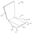
乳母車は、好ましくは、図9に示すような座席芯材60を有している。この座席芯材60は、乳母車の車体に取付けられるものであり、屈曲可能に接続された座面芯材61と、背もたれ面芯材62とを備える。座面芯材61は、折畳み時に幅方向の寸法を縮小できるように、屈曲可能に連結された中央部分61aと、1対の側方部分61bとを有する。折畳み時には、1対の側方部分61bは、図中、矢印Aで示す方向に回動する。
【0036】
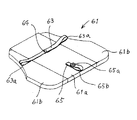
図10は、座面芯材61の裏面を示している。図示するように、座面芯材61の裏面には、後部ベルト63と前部ベルト65とが取付けられている。後部ベルト63は、例えば、びょう64を介して座面芯材61に取付けられており、その両側部にループ部63aを有している。前部ベルト65も、例えば、びょうを介して座面芯材61に取付けられており、止めボタン65aを止めることによってループ部65bを形成する。
【0037】
図11は、座面芯材61と、1対の座面支持サイド棒25との取付け状態を示す平面図である。図示するように、後部ベルト63の両側方端にあるループ部63aは1対の座面支持サイド棒25の内方張出部25aに嵌められ、前部ベルト65のループ部65bは、屈曲リンク部材26の中央リンク棒26aに嵌められる。
【0038】
上記のように、座面芯材61を1対の座面支持サイド棒25に、例えばベルトを介して連結し、さらにこの座面芯材61を1対の内方張出部25aによって下方から安定して支えることにより、座面芯材61によって形成される座面の位置を確実に安定させることができる。
【0039】
以上、この発明の一実施形態を図面を参照しながら説明したが、以上に説明し図示した形態は、例示的なものである。したがって、この発明と同一の範囲内において、あるいは均等の範囲内において、種々の修正や変更を加えることが可能である。以下に、そのいくつかを例示的に列挙して説明する。
【0040】
(1)図示した実施形態では、座面の後方部を下から安定して支持する内方張出部は、座面支持サイド棒の後方端部分をU字状に折り曲げることによって形成されていた。しかしながら、このようなU字状の折り曲げ形状に限定されるものではなく、種々の形状が考えられる。要するに、内側方に向かって張り出し、座面を下から支えられるような形状のものであればよい。
【0041】
(2)内方張出部を、座面支持サイド棒とは別部材で構成するようにしてもよい。この場合、好ましくは、内方張出部は、座面支持サイド棒に一体的に固定される。
【図面の簡単な説明】
【図1】特開平8−58599号公報に開示された乳母車を示す斜視図である。
【図2】図1の乳母車の折畳み状態を示す斜視図である。
【図3】図1の乳母車の座部を上方から見た図である。
【図4】この発明の一実施形態の斜視図である。
【図5】図4に示した乳母車の折畳み状態の背面図である。
【図6】側部縦棒と後脚と座面支持サイド棒との連結部分を示す斜視図である。
【図7】図6に示す連結部分の折畳み動作の途中の状態を示す図である。
【図8】図6に示す連結部分の折畳み状態を示す図である。
【図9】座席芯材を示す斜視図である。
【図10】座席芯材の裏面を示す斜視図である。
【図11】座面芯材と1対の座面支持サイド棒との取付け状態を示す平面図である。
【符号の説明】
20 乳母車、21 前輪、22 後輪、23 前脚、24 後脚、25 座面支持サイド棒、25a 内方張出部、26 屈曲リンク部材、27 前脚連結部材、28 後脚連結部材、29 手摺部材、30 前ガード部材、31 反転部材、32 連結部材、33 背面ベルト、34 スライド部材、40 押棒、41 側部縦棒、42 カバー部材、43 中間棒、45 操作ボタン、46 連結軸、47 連結軸、60 座席芯材、61 座面芯材、62 背もたれ面芯材、63 後部ベルト、65 前部ベルト。[0001]
TECHNICAL FIELD OF THE INVENTION
The present invention relates to a foldable baby carriage that is folded so as to reduce its width dimension, and more particularly to a foldable baby carriage that prevents a rear portion of a seat from dropping.
[0002]
[Prior art]
1 and 2 show a baby carriage disclosed in Japanese Patent Application Laid-Open No. 8-58599. FIG. 1 shows the stroller in an open state, and FIG. 2 shows the stroller in a folded state. As is apparent from a comparison between FIG. 1 and FIG. 2, the
[0003]
The illustrated
[0004]
The
[0005]
The lower frame structure, which is located on the four
[0006]
The seat hammock 3 has a
[0007]
FIG. 3 is a view of the
[0008]
In order to enable the above folding operation, the front portions of the pair of seating surface
[0009]
When the
[0010]
[Patent Document 1]
JP-A-8-58599
[Problems to be solved by the invention]
In the stroller disclosed in Japanese Patent Application Laid-Open No. 8-58599, the rear part of the
[0012]
Therefore, during use of the stroller, the rear portion of the
[0013]
SUMMARY OF THE INVENTION An object of the present invention is to provide a stroller that can be folded so that its width dimension is reduced and that can stably support a seat surface of the stroller in an open state and maintain a proper sitting posture of a child. To provide.
[0014]
[Means for Solving the Problems]
A folding stroller according to the present invention is folded so that its width dimension is reduced, and has a pair of front and rear extending portions on both sides of the seat surface for supporting the seat surface from below. A seat support side bar is provided. Each seating surface support side bar has a rigid inward projection that projects inward to support the seating surface from below.
[0015]
The rigid inwardly extending portion stably supports the seating surface from below, so that the seating surface does not fall down and the child's sitting posture can be properly maintained. Particularly, from the viewpoint of preventing the rear portion of the seat from dropping, the inwardly extending portion preferably extends inward from the rear portion of the seat-side supporting side bar.
[0016]
Preferably, each seat surface support side bar has an inwardly extending portion integrally. Although it is possible to configure the seat surface support side rod and the inwardly extending portion as separate members, even in such a case, if both are integrated, the rigidity increases, so that the seat surface can be stably supported. it can.
[0017]
In one embodiment, the inward protrusion is formed by bending a rear end portion of the seat surface support side bar inwardly into a U-shape. With the seating surface supporting side bar having such a shape, the seating surface can be stably supported by a very simple mechanism.
[0018]
As an example of a specific form, the stroller is rotatably connected to a rear leg having a rear wheel and a rear leg via a connecting pin, and is in a folded state along the rear leg above the connecting pin in the open state. , A reversing member is provided along the rear leg below the connecting pin, and a connecting member rotatably connected to the reversing member. Preferably, the seat surface support side bar and the connecting member are fixed, and a portion of the seat surface support side bar extending rearward beyond the connecting member is bent in a U-shape.
[0019]
Preferably, the interval between the pair of inwardly extending portions located on the left and right in the open state of the stroller has a dimension corresponding to the distance that the pair of seating surface support side bars approach each other with the folding operation. Such a dimensional relationship does not hinder the folding operation.
[0020]
In one embodiment, the stroller includes a plate-shaped seating surface core member forming a seating surface. The seat core is preferably connected to a pair of seat support side bars. With such a configuration, the position of the seating surface core member is fixed and is stably supported from below by the inwardly extending portion, so that the position of the seating surface can be reliably stabilized. In this case, the seat core is preferably connected to the inwardly projecting portions of the pair of seat support side bars.
[0021]
In the above case, the seat core material and the pair of seat support side bars are connected via, for example, a belt. Also, preferably, the stroller includes a bent link member that connects between the front portions of the pair of seating surface support side bars. This bending link member has a center link rod provided to be bendable and a pair of side link rods. The seat core is preferably connected to the central link bar.
[0022]
BEST MODE FOR CARRYING OUT THE INVENTION
An embodiment of the present invention will be described with reference to the drawings. FIG. 4 is a perspective view of the
[0023]
The illustrated
[0024]
In order to realize the folding operation of the
[0025]
The front end portion of the seat surface
[0026]
The inverted
[0027]
In order to allow the left and right wheels to approach each other at the time of folding and reduce the width dimension, a
[0028]
The rear
[0029]
With reference to FIGS. 6 to 8, a connection structure of the side
[0030]
A connecting
[0031]
A reversing
[0032]
The lower end of each side
[0033]
A
[0034]
In the open state of the stroller shown in FIG. 6, the
[0035]
The stroller preferably has a
[0036]
FIG. 10 shows the back surface of the
[0037]
FIG. 11 is a plan view showing a mounting state of the
[0038]
As described above, the seating
[0039]
As described above, one embodiment of the present invention has been described with reference to the drawings, but the embodiment described and illustrated above is merely an example. Therefore, various modifications and changes can be made within the same range as the present invention or within an equivalent range. Hereinafter, some of them will be enumerated and described.
[0040]
(1) In the illustrated embodiment, the inward protruding portion that stably supports the rear portion of the seat from below is formed by bending the rear end portion of the seat surface supporting side bar into a U-shape. . However, the present invention is not limited to such a U-shaped bent shape, and various shapes are conceivable. In short, any shape may be used as long as it protrudes inward and can support the seat surface from below.
[0041]
(2) The inwardly extending portion may be formed of a member different from the seat surface supporting side bar. In this case, preferably, the inwardly extending portion is integrally fixed to the seating surface support side bar.
[Brief description of the drawings]
FIG. 1 is a perspective view showing a baby carriage disclosed in Japanese Patent Application Laid-Open No. 8-58599.
FIG. 2 is a perspective view showing the baby carriage of FIG. 1 in a folded state.
FIG. 3 is a view of the stroller of FIG. 1 as viewed from above.
FIG. 4 is a perspective view of one embodiment of the present invention.
5 is a rear view of the stroller shown in FIG. 4 in a folded state.
FIG. 6 is a perspective view showing a connecting portion of a side vertical bar, a rear leg, and a seat surface supporting side bar.
FIG. 7 is a view showing a state in the middle of the folding operation of the connecting portion shown in FIG. 6;
FIG. 8 is a view showing a folded state of the connecting portion shown in FIG. 6;
FIG. 9 is a perspective view showing a seat core.
FIG. 10 is a perspective view showing a back surface of a seat core material.
FIG. 11 is a plan view showing an attached state of a seat core member and a pair of seat support side bars.
[Explanation of symbols]
Claims (10)
座面を下から支持するために座面の両側部において前後方向に延びる1対の座面支持サイド棒を備え、
前記各座面支持サイド棒は、座面を下から支え得るように内側方に向かって張り出した剛性のある内方張出部を有する、折畳式乳母車。A foldable stroller that is folded so that its width dimension is reduced,
A pair of seating surface support side bars extending in the front-rear direction on both sides of the seating surface to support the seating surface from below,
A folding stroller, wherein each of the seating surface support side bars has a rigid inwardly extending portion that extends inward so as to support the seating surface from below.
前記後脚に連結ピンを介して回動可能に連結され、開状態においては前記連結ピンの上方で前記後脚に沿い、折畳み状態においては前記連結ピンの下方で前記後脚に沿う反転部材と、
前記反転部材に回動可能に連結された連結部材とを備え、
前記座面支持サイド棒と前記連結部材とは固定されており、
前記座面支持サイド棒のうち、前記連結部材を超えて後方に延びている部分がU字状に折り曲げられている、請求項4に記載の折畳式乳母車。A rear leg having a rear wheel;
A reversing member that is rotatably connected to the rear leg via a connection pin, and is located along the rear leg above the connection pin in the open state, and below the connection pin in the folded state below the connection pin in the folded state; ,
A connecting member rotatably connected to the reversing member,
The seat surface support side bar and the connecting member are fixed,
The foldable stroller according to claim 4, wherein a portion of the seat supporting side bar extending rearward beyond the connecting member is bent in a U-shape.
前記座面芯材は、前記1対の座面支持サイド棒に連結されている、請求項1〜6のいずれかに記載の折畳式乳母車。With a plate-shaped seating surface core material forming a seating surface,
The foldable baby carriage according to any one of claims 1 to 6, wherein the seat core member is connected to the pair of seat support side bars.
前記屈曲リンク部材は、屈曲可能に設けられた中央リンク棒と、1対のサイドリンク棒とを有し、
前記座面芯材は、前記中央リンク棒に連結されている、請求項7〜9のいずれかに記載の折畳式乳母車。A bending link member connecting between the front portions of the pair of seating surface support side bars;
The bending link member has a center link rod provided to be bent, and a pair of side link rods,
The foldable baby carriage according to any one of claims 7 to 9, wherein the seat core member is connected to the center link rod.
Priority Applications (6)
| Application Number | Priority Date | Filing Date | Title |
|---|---|---|---|
| JP2003026602A JP4299016B2 (en) | 2003-02-04 | 2003-02-04 | Folding baby carriage |
| US10/753,095 US7140634B2 (en) | 2003-02-04 | 2004-01-06 | Foldable baby carriage |
| TW093100415A TWI233411B (en) | 2003-02-04 | 2004-01-08 | Foldable baby carriage |
| EP04001485A EP1445166B1 (en) | 2003-02-04 | 2004-01-23 | Foldable baby carriage |
| KR1020040006873A KR100550747B1 (en) | 2003-02-04 | 2004-02-03 | Foldable Baby Carriage |
| CNB2004100040700A CN100363220C (en) | 2003-02-04 | 2004-02-04 | Folding perambulator |
Applications Claiming Priority (1)
| Application Number | Priority Date | Filing Date | Title |
|---|---|---|---|
| JP2003026602A JP4299016B2 (en) | 2003-02-04 | 2003-02-04 | Folding baby carriage |
Publications (2)
| Publication Number | Publication Date |
|---|---|
| JP2004237784A true JP2004237784A (en) | 2004-08-26 |
| JP4299016B2 JP4299016B2 (en) | 2009-07-22 |
Family
ID=32652960
Family Applications (1)
| Application Number | Title | Priority Date | Filing Date |
|---|---|---|---|
| JP2003026602A Expired - Fee Related JP4299016B2 (en) | 2003-02-04 | 2003-02-04 | Folding baby carriage |
Country Status (6)
| Country | Link |
|---|---|
| US (1) | US7140634B2 (en) |
| EP (1) | EP1445166B1 (en) |
| JP (1) | JP4299016B2 (en) |
| KR (1) | KR100550747B1 (en) |
| CN (1) | CN100363220C (en) |
| TW (1) | TWI233411B (en) |
Cited By (2)
| Publication number | Priority date | Publication date | Assignee | Title |
|---|---|---|---|---|
| EP1762458A1 (en) | 2005-09-07 | 2007-03-14 | Aprica Ikujikenkyukai Aprica Kassai Kabushikikaisha | Folding baby carriage |
| JP2013244942A (en) * | 2012-05-29 | 2013-12-09 | Combi Corp | Stroller and seat unit |
Families Citing this family (16)
| Publication number | Priority date | Publication date | Assignee | Title |
|---|---|---|---|---|
| JP4299016B2 (en) * | 2003-02-04 | 2009-07-22 | グラコ・チルドレンズ・プロダクツ・インコーポレイテッド | Folding baby carriage |
| JP3967271B2 (en) * | 2003-02-04 | 2007-08-29 | アップリカ育児研究会アップリカ▲葛▼西株式会社 | Folding baby carriage |
| KR101368447B1 (en) * | 2005-09-30 | 2014-02-28 | 콤비 가부시키가이샤 | Stroller |
| CN100581894C (en) * | 2006-01-05 | 2010-01-20 | 东莞市寮步齐家日用品设计服务部 | Double stroller for front and rear seats |
| USD547919S1 (en) * | 2006-03-30 | 2007-07-31 | Play, S.A. | Shopping cart |
| US20090102149A1 (en) * | 2007-10-22 | 2009-04-23 | Graco Children's Products Inc. | Foldable pushcart and foldable baby carriage |
| WO2009089540A2 (en) * | 2008-01-10 | 2009-07-16 | Graco Children's Products Inc. | One-hand fold stroller frame |
| CN101844574B (en) * | 2009-03-23 | 2013-02-13 | 明门香港股份有限公司 | cart |
| US20130001939A1 (en) * | 2011-06-28 | 2013-01-03 | Lynne Marie Celia | Saftey roll bar for strollers |
| CN105752146B (en) * | 2011-11-01 | 2019-07-09 | 康贝株式会社 | baby carriage |
| GB2502864B (en) * | 2012-04-05 | 2014-09-24 | Wonderland Nursery Goods | Infant stroller apparatus |
| US9266550B1 (en) | 2014-09-03 | 2016-02-23 | Vipul Shah | Handle for stroller |
| USD808104S1 (en) * | 2016-01-05 | 2018-01-16 | Inmarket B.V. | Trolley |
| KR200482231Y1 (en) | 2016-06-17 | 2017-01-02 | 주식회사 쭈쭈베베 | Foldable stroller having handle structure for carrier |
| CN106275038B (en) * | 2016-09-29 | 2018-10-26 | 昆山爱儿特儿童用品有限公司 | Foldable carriage for children |
| CN108263463B (en) * | 2018-03-07 | 2023-08-01 | 深圳市秀宝婴童用品有限公司 | But handcart of secondary flexible folding |
Family Cites Families (24)
| Publication number | Priority date | Publication date | Assignee | Title |
|---|---|---|---|---|
| GB1469770A (en) | 1973-11-19 | 1977-04-06 | Lamondine Sa | Folding chairs |
| US4256325A (en) | 1977-01-13 | 1981-03-17 | Henry Fleischer | Collapsible frames for baby carriers |
| US4191397A (en) * | 1977-06-15 | 1980-03-04 | Kassai Kabushikikaisha | Baby carriage |
| JPS58202158A (en) | 1982-05-21 | 1983-11-25 | アップリカ葛西株式会社 | Handrail of baby carriage |
| US4616844A (en) * | 1983-07-15 | 1986-10-14 | Aprica Kassai Kabushikikaisha | Mechanism for locking opened state of baby carriage |
| KR890003001Y1 (en) * | 1986-12-03 | 1989-05-13 | 주식회사 대아휴먼엔지니어링 | Folding device for baby car |
| JPH04154477A (en) * | 1990-10-16 | 1992-05-27 | Konbi Kk | Folding mechanism of stroller |
| JP3040496B2 (en) * | 1991-01-11 | 2000-05-15 | アップリカ▲葛▼西株式会社 | Folding stroller and folding mechanism used therein |
| US5358263A (en) * | 1993-04-30 | 1994-10-25 | Aldus Richard E | Travel-air chair |
| JP3311160B2 (en) * | 1994-08-19 | 2002-08-05 | アップリカ▲葛▼西株式会社 | Baby carriage seat |
| TW280801B (en) * | 1994-12-26 | 1996-07-11 | Aprica Kassai Kk | |
| US5988670A (en) * | 1995-02-15 | 1999-11-23 | Jiangsu Goodbaby Group, Inc. | Child carrier |
| US5820144A (en) * | 1996-05-31 | 1998-10-13 | Wang; Frank | Stroller with shock absorbing device for mounting a seat member on a stroller frame |
| US5863061A (en) * | 1996-10-25 | 1999-01-26 | Ziegler; Scott William | Collapsible three wheeled stroller |
| JP2846299B2 (en) * | 1997-04-28 | 1999-01-13 | アップリカ▲葛▼西株式会社 | Folding baby carriage |
| US6000713A (en) * | 1998-12-22 | 1999-12-14 | Lin; Hui-Liang | Foldable two-wheeled baby stroller |
| US6196572B1 (en) * | 1999-01-19 | 2001-03-06 | Greg R. Durrin | Convertible jogging stroller and trailer |
| JP2002012155A (en) * | 2000-06-30 | 2002-01-15 | Combi Corp | stroller |
| JP4990451B2 (en) * | 2001-08-30 | 2012-08-01 | コンビ株式会社 | Tri-fold stroller |
| SG135046A1 (en) * | 2001-09-19 | 2007-09-28 | Combi Co | Stroller |
| US6601865B1 (en) * | 2002-05-23 | 2003-08-05 | Sebert Harper | Visually appealing versatile rollable and foldable chair |
| US6789809B2 (en) * | 2002-09-09 | 2004-09-14 | Ken Lin | Push cart transferable to a back holder or a chair |
| JP4299016B2 (en) * | 2003-02-04 | 2009-07-22 | グラコ・チルドレンズ・プロダクツ・インコーポレイテッド | Folding baby carriage |
| KR101519156B1 (en) * | 2009-02-25 | 2015-05-11 | 엘지전자 주식회사 | Refrigerator |
-
2003
- 2003-02-04 JP JP2003026602A patent/JP4299016B2/en not_active Expired - Fee Related
-
2004
- 2004-01-06 US US10/753,095 patent/US7140634B2/en not_active Expired - Fee Related
- 2004-01-08 TW TW093100415A patent/TWI233411B/en not_active IP Right Cessation
- 2004-01-23 EP EP04001485A patent/EP1445166B1/en not_active Expired - Lifetime
- 2004-02-03 KR KR1020040006873A patent/KR100550747B1/en not_active Expired - Fee Related
- 2004-02-04 CN CNB2004100040700A patent/CN100363220C/en not_active Expired - Fee Related
Cited By (3)
| Publication number | Priority date | Publication date | Assignee | Title |
|---|---|---|---|---|
| EP1762458A1 (en) | 2005-09-07 | 2007-03-14 | Aprica Ikujikenkyukai Aprica Kassai Kabushikikaisha | Folding baby carriage |
| US7419181B2 (en) | 2005-09-07 | 2008-09-02 | Aprica Ikujikenkyukai Aprica Kassai Kabushikikaisha | Foldable carriage body for carrying a seat |
| JP2013244942A (en) * | 2012-05-29 | 2013-12-09 | Combi Corp | Stroller and seat unit |
Also Published As
| Publication number | Publication date |
|---|---|
| TWI233411B (en) | 2005-06-01 |
| CN1519156A (en) | 2004-08-11 |
| US7140634B2 (en) | 2006-11-28 |
| CN100363220C (en) | 2008-01-23 |
| KR100550747B1 (en) | 2006-02-08 |
| EP1445166A1 (en) | 2004-08-11 |
| JP4299016B2 (en) | 2009-07-22 |
| KR20040071618A (en) | 2004-08-12 |
| EP1445166B1 (en) | 2006-10-25 |
| US20040164523A1 (en) | 2004-08-26 |
| TW200422217A (en) | 2004-11-01 |
Similar Documents
| Publication | Publication Date | Title |
|---|---|---|
| JP4299016B2 (en) | Folding baby carriage | |
| JP2004291661A (en) | Foldable baby carriage | |
| JP4234512B2 (en) | child seat | |
| US7229083B2 (en) | Stroller on which basket can be mounted | |
| JPS5833148B2 (en) | baby carriage seat | |
| JPH0126910B2 (en) | ||
| JP2004058985A (en) | Child-care instrument | |
| CN104395174B (en) | Stroller and seat unit | |
| CN103057577B (en) | Perambulator | |
| JP7617168B2 (en) | Child Support Device | |
| JP4757594B2 (en) | stroller | |
| JP3981027B2 (en) | Child care equipment seat hammock | |
| WO2018051807A1 (en) | Stroller | |
| JP4855035B2 (en) | stroller | |
| KR20150005467A (en) | Stroller | |
| JP2014061768A (en) | Baby carriage | |
| TWI755566B (en) | Stroller and holding member | |
| JP2005132245A (en) | Folding buggy | |
| JP2011063097A (en) | Folding type baby carriage | |
| JP4188016B2 (en) | stroller | |
| CN104163192B (en) | Perambulator | |
| JP6758905B2 (en) | baby carriage | |
| KR20150005466A (en) | Stroller | |
| CN120039301A (en) | Restraint device of child care device with seat | |
| JPH07242177A (en) | Folding stroller |
Legal Events
| Date | Code | Title | Description |
|---|---|---|---|
| A621 | Written request for application examination |
Free format text: JAPANESE INTERMEDIATE CODE: A621 Effective date: 20051110 |
|
| A711 | Notification of change in applicant |
Free format text: JAPANESE INTERMEDIATE CODE: A711 Effective date: 20080401 |
|
| A131 | Notification of reasons for refusal |
Free format text: JAPANESE INTERMEDIATE CODE: A131 Effective date: 20080520 |
|
| RD03 | Notification of appointment of power of attorney |
Free format text: JAPANESE INTERMEDIATE CODE: A7423 Effective date: 20080523 |
|
| A521 | Request for written amendment filed |
Free format text: JAPANESE INTERMEDIATE CODE: A523 Effective date: 20080717 |
|
| TRDD | Decision of grant or rejection written | ||
| A01 | Written decision to grant a patent or to grant a registration (utility model) |
Free format text: JAPANESE INTERMEDIATE CODE: A01 Effective date: 20090407 |
|
| A01 | Written decision to grant a patent or to grant a registration (utility model) |
Free format text: JAPANESE INTERMEDIATE CODE: A01 |
|
| A61 | First payment of annual fees (during grant procedure) |
Free format text: JAPANESE INTERMEDIATE CODE: A61 Effective date: 20090416 |
|
| R150 | Certificate of patent or registration of utility model |
Free format text: JAPANESE INTERMEDIATE CODE: R150 |
|
| FPAY | Renewal fee payment (event date is renewal date of database) |
Free format text: PAYMENT UNTIL: 20120424 Year of fee payment: 3 |
|
| FPAY | Renewal fee payment (event date is renewal date of database) |
Free format text: PAYMENT UNTIL: 20120424 Year of fee payment: 3 |
|
| S111 | Request for change of ownership or part of ownership |
Free format text: JAPANESE INTERMEDIATE CODE: R313113 |
|
| FPAY | Renewal fee payment (event date is renewal date of database) |
Free format text: PAYMENT UNTIL: 20120424 Year of fee payment: 3 |
|
| R360 | Written notification for declining of transfer of rights |
Free format text: JAPANESE INTERMEDIATE CODE: R360 |
|
| FPAY | Renewal fee payment (event date is renewal date of database) |
Free format text: PAYMENT UNTIL: 20120424 Year of fee payment: 3 |
|
| FPAY | Renewal fee payment (event date is renewal date of database) |
Free format text: PAYMENT UNTIL: 20120424 Year of fee payment: 3 |
|
| R350 | Written notification of registration of transfer |
Free format text: JAPANESE INTERMEDIATE CODE: R350 |
|
| FPAY | Renewal fee payment (event date is renewal date of database) |
Free format text: PAYMENT UNTIL: 20120424 Year of fee payment: 3 |
|
| FPAY | Renewal fee payment (event date is renewal date of database) |
Free format text: PAYMENT UNTIL: 20130424 Year of fee payment: 4 |
|
| FPAY | Renewal fee payment (event date is renewal date of database) |
Free format text: PAYMENT UNTIL: 20130424 Year of fee payment: 4 |
|
| FPAY | Renewal fee payment (event date is renewal date of database) |
Free format text: PAYMENT UNTIL: 20140424 Year of fee payment: 5 |
|
| R250 | Receipt of annual fees |
Free format text: JAPANESE INTERMEDIATE CODE: R250 |
|
| S533 | Written request for registration of change of name |
Free format text: JAPANESE INTERMEDIATE CODE: R313533 |
|
| R360 | Written notification for declining of transfer of rights |
Free format text: JAPANESE INTERMEDIATE CODE: R360 |
|
| R360 | Written notification for declining of transfer of rights |
Free format text: JAPANESE INTERMEDIATE CODE: R360 |
|
| R371 | Transfer withdrawn |
Free format text: JAPANESE INTERMEDIATE CODE: R371 |
|
| S533 | Written request for registration of change of name |
Free format text: JAPANESE INTERMEDIATE CODE: R313533 |
|
| R350 | Written notification of registration of transfer |
Free format text: JAPANESE INTERMEDIATE CODE: R350 |
|
| R250 | Receipt of annual fees |
Free format text: JAPANESE INTERMEDIATE CODE: R250 |
|
| R250 | Receipt of annual fees |
Free format text: JAPANESE INTERMEDIATE CODE: R250 |
|
| R250 | Receipt of annual fees |
Free format text: JAPANESE INTERMEDIATE CODE: R250 |
|
| LAPS | Cancellation because of no payment of annual fees |