【0001】
【発明の属する技術分野】
本発明は、外側部材の内周面に環状部材の外周面を嵌合し、環状部材の内周面に内側部材の外周面を嵌合した二重嵌合部をシールするシール構造に関するものである。
【0002】
【従来の技術】
入力ロッド引張り式ブレーキ倍力装置は、例えば特開2001−294138号公報に記載されているように、マスタシリンダ装置のマスタシリンダに第1マスタピストンが嵌合され、該第1マスタピストンから離れた後側に第2マスタピストンが嵌合され、第1マスタピストンに一体に形成されたピストンロッドが第2マスタピストンを貫通してマスタシリンダの後端壁から突出し、ブレーキブースタ装置により作動されるようになっている。係る入力ロッド引張り式ブレーキ倍力装置では、第2マスタピストンは外周面でマスタシリンダと液密的に嵌合し、内周面でピストンロッドと液密的に嵌合しなければならない。
【0003】
また、特開昭56−154357号公報に記載された入力ロッド引張り式ブレーキ倍力装置では、マスタシリンダ装置の前端にブレーキブースタ装置が取付けられ、ブレーキブースタがダイヤフラムにより定圧室と変圧室とに区画され、変圧室を大気と定圧室とに切換えて連通する弁機構を作動する入力ロッドがマスタピストンおよびマスタシリンダを貫通して延在しブレーキペダルに連結されている。そして、マスタピストンが外周面でマスタシリンダと嵌合し、内周面で入力ロッドと嵌合する二重嵌合部を液密的にシールするシール構造として、マスタシリンダの内周面に当接する外側リップがベース部の外周縁から軸線方向に突設され、入力ロッドの外周面に当接する内側リップがベース部の内周縁から軸線方向に突設されたシール部材がマスタピストンの端面にベース部の裏面で当接されている。他のシール構造として、マスタピストンの外周面および内周面とマスタシリンダの内周面および入力ロッドの外周面との間をそれぞれシールするシール部材がマスタピストンに個々に装着されている。
【0004】
【特許文献1】
特開2001−294138号公報(第3,4頁、図2)
【0005】
【特許文献2】
特開昭56−154357号公報(第5,6頁、図1,2)
【0006】
【発明が解決しようとする課題】
上述のようなベース部の外周縁および内周縁から外側および内側リップを突設しただけのシール部材では、外側および内側リップの一方に作用する力によるシール部材の移動が他方に影響し、両リップのシール作用が互いに干渉してシール性能を低下する虞がある。また、二重嵌合部をそれぞれシールする個々のシール部材をマスタピストンに設けると、マスタピストンの外径または全長が大きくなる不具合があった。
【0007】
本発明は、係る従来の不具合を解消するためになされたもので、二重嵌合部をシールするシール構造をシール性能を損なうことなく小型化することである。
【0008】
【課題を解決するための手段】
上記の課題を解決するため、請求項1に記載の発明の構成上の特徴は、外側部材の内周面に環状部材の外周面を嵌合し、該環状部材の内周面に内側部材の外周面を嵌合した二重嵌合部をシールするシール構造において、前記環状部材の端面に内外周の中央部分に環状突起を突設し、シール部材のベース部の裏面に前記環状突起に係合する環状溝を刻設し、該環状溝を前記環状突起に嵌合させて前記シール部材を前記環状部材の端面に当接し、前記シール部材には、前記外側部材の内周面に当接する外側リップを前記ベース部の外周縁から軸線方向に突設し、前記内側部材の外周面に当接する内側リップを前記ベース部の内周縁から軸線方向に突設し、且つ前記ベース部の表面に前記外側リップと内側リップとの間に環状の分離帯を形成したことである。
【0009】
請求項2に係る発明の構成上の特徴は、請求項1において、頭部を有する複数個の係合柱を前記環状突起から立設し、該係合柱に係合する複数の係合穴を前記分離帯に穿設し、該係合穴を前記係合柱に挿通して前記頭部により抜け止めした状態で前記環状溝を前記環状突起に嵌合し、前記ベース部を前記環状部材の端面に当接して取付けたことである。
【0010】
請求項3に係る発明の構成上の特徴は、ブレーキブースタをダイヤフラムにより定圧室と変圧室とに区画し、入力ロッドにより作動され前記変圧室を大気と前記定圧室とに切換えて連通し前記ダイヤフラムを進退させる弁機構を前記ダイヤフラムに固着したピストンに設け、シリンダボディに穿設したマスタシリンダにマスタピストンを摺動自在に嵌合し、該マスタピストンに嵌合するピストンロッドを前記ダイヤフラムの後退に基づいて後方に軸動してブレーキ液圧を発生する入力ロッド引張り式ブレーキ倍力装置において、前記シリンダボディ、マスタピストンおよびピストンロッドをそれぞれ前記外側部材、環状部材および内側部材とし、前記シリンダ内周面とマスタピストンの外周面との間、および前記マスタピストンの内周面と前記ピストンロッドの外周面との間を請求項1または2に記載のシール構造によりシールしたことである。
【0011】
請求項4に係る発明の構成上の特徴は、ブレーキブースタをダイヤフラムにより定圧室と変圧室とに区画し、入力ロッドにより作動され前記変圧室を大気と前記定圧室とに切換えて連通し前記ダイヤフラムを進退させる弁機構を前記ダイヤフラムに固着したピストンに設け、シリンダボディに穿設したマスタシリンダに第1および第2マスタピストンを摺動自在に嵌合し、該第2マスタピストンを貫通して前記第1マスタピストンに連結されたピストンロッドを前記ダイヤフラムの後退に基づいて後方に軸動してブレーキ液圧を発生する入力ロッド引張り式ブレーキ倍力装置において、前記シリンダボディ、第2マスタピストンおよびピストンロッドをそれぞれ前記外側部材、環状部材および内側部材とし、前記マスタシリンダ内周面と前記第2マスタピストンの外周面との間、および前記第2マスタピストンの内周面と前記ピストンロッドの外周面との間を請求項1または2に記載のシール構造によりシールしたことである。
【0012】
請求項5に係る発明の構成上の特徴は、請求項4において、前記第1および第2マスタピストンの間に第1圧縮スプリングをバネ受けで挟持して介在し、前記シール部材が前端面に当接された前記第2マスタピストンを前記バネ受けの後端面に第2圧縮スプリングにより押圧することである。
【0013】
【発明の作用・効果】
上記のように構成した請求項1に係る発明においては、環状部材の端面に向けて液圧が作用すると、シール部材のベース部が環状部材の端面に押圧され、外側および内側リップが液圧により外側部材の内周面および内側部材の外周面にそれぞれ圧接され、外側部材の内周面と環状部材の外周面との間および環状部材の内周面と内側部材の外周面との間がシールされる。このとき、ベース部の裏面に刻設され環状部材の端面に突設された環状突起に嵌合された環状溝の両溝面が分離帯の両側面に作用する液圧により環状突起の両側壁に圧接されるので、外側部材の内周面と環状部材の外周面との間および環状部材の内周面と内側部材の外周面との間を夫々シールする断面カップ形状の2個のシール部材を設けたように作動し、外側および内側リップの一方に作用する力によりシール部材が半径方向に移動し、他方のリップのシール作用に影響してシール性能を低下することを防止できる。また、一のシール部材により二重嵌合部をシールできるので、二重嵌合部のシール構造を小型化することができる。
【0014】
上記のように構成した請求項2に係る発明においては、環状部材の端面に立設した複数の係合柱にシール部材の係合穴を挿通し、係合柱の頭部により抜け止めしているので、環状部材の端面に負圧が作用してもシール部材が環状部材から離脱することを防止できる。
【0015】
上記のように構成した請求項3に係る発明においては、入力ロッドにより弁機構が作動されると大気が変圧室に導入されてダイヤフラムが後退され、ダイヤフラムの後退に基づいてピストンロッドが後方に軸動されてブレーキ液圧が発生される。ピストンロッドに嵌装されたマスタピストンの端面に液圧が作用すると、シール部材のベース部がマスタピストンの端面に押圧され、外側および内側リップが液圧によりマスタシリンダの内周面およびピストンロッドの外周面にそれぞれ圧接される。これにより、マスタシリンダの内周面とマスタピストンの外周面との間およびマスタピストンの内周面とピストンロッドの外周面との間をシールするシール構造をシール性能を損なうことなく小さくすることができ、小型で高性能な入力ロッド引張り式ブレーキ倍力装置を提供することができる。
【0016】
上記のように構成した請求項4に係る発明においては、入力ロッドにより弁機構が作動されると大気が変圧室に導入されてダイヤフラムが後退され、第2マスタピストンを貫通して第1マスタピストンに連結されたピストンロッドがダイヤフラムの後退に基づいて後方に軸動されてブレーキ液圧が発生される。第2マスタピストンの前端に液圧が作用すると、シール部材のベース部が第2マスタピストンの前端面に押圧され、外側および内側リップが液圧によりマスタシリンダの内周面およびピストンロッドの外周面にそれぞれ圧接される。これにより、マスタシリンダの内周面と第2マスタピストンの外周面との間および第2マスタピストンの内周面とピストンロッドの外周面との間をシールするシール構造をシール性能を損なうことなく小さくすることができ、小型で高性能なタンデム式の入力ロッド引張り式ブレーキ倍力装置を提供することができる。
【0017】
上記のように構成した請求項5に係る発明においては、第2マスタピストンは第2圧縮スプリングにより前方に付勢され、第1圧縮スプリングを挟持するバネ受けの後端面に押圧されるので、第2マスタピストンの前端面に当接されたシール部材が第2マスタピストンから離脱することがない。
【0018】
【実施の形態】
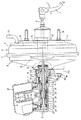
以下、本発明に係るシール構造を入力ロッド引張り式ブレーキ倍力装置に適用した実施の形態を図面に基づいて説明する。図1において、1は入力ロッド引張り式倍力装置で、ブレーキブースタ装置2とマスタシリンダ装置3を結合して構成されている。入力ロッド引張り式倍力装置1はエンジンルームと車室内とを仕切る車輌のダッシュボード4に固定され、ダッシュボード4の車室側に装架されたブレーキペダル5により入力ロッド6が後方に引っ張られることによりマスタシリンダ装置3から図略のホイールシリンダにブレーキ液圧が送出される。
【0019】
ブレーキブースタ装置2は、ブースタ7を形成するフロントシェル8及びリアシェル9を有し、両シェル8,9間に挟着されたダイヤフラム10によりブースタ7の内部が定圧室11と変圧室12とに区画されている。リアシェル9には負圧導入管13が取付けられ、定圧室11は負圧導入管13を介してエンジンの吸気マニホールドに連通されて負圧に維持されている。ダイヤフラム10にピストン14が固定され、入力ロッド6により作動されて変圧室12を大気と定圧室11とに切換えて連通しダイヤフラム10を進退させる弁機構15がピストン14に内蔵されている。フロントシェル8とリアシェル9とは円周上2本のタイロッド16で結合されている。ブレーキブースタ装置2は、フロントシェル8の前端面がマスタシリンダ装置3のシリンダボディ17に形成されたフランジ部17aの後端面に当接され、タイロッド16の前端部16aがフランジ部17aに穿設された結合穴に挿通され、前端部16bに刻設された雄ねじにナット18が螺着されてマスタシリンダ装置3と結合されている。
【0020】
シリンダボディ17にはマスタシリンダ20をなすシリンダ20a、装着孔21が同軸に形成され、装着孔21にカップ状の閉塞部材22の先端小径部がシールされて嵌合され、閉塞部材22の前端面と装着孔21の肩部との間にはリング体23とシール部材24とが介在されている。閉塞部材22は、外周ねじ部が装着孔21に螺着されてシリンダボディ17の後端部に固定されている。ブレーキブースタ装置2の出力ロッド19は閉塞部材22の後端底部をシール部材25によりシールされて貫通し、マスタシリンダ20内にピストンロッド26として前方に延在している。閉塞部材22の前端小径部にはマスタシリンダ20の後端部をなすシリンダ20bが形成されている。
【0021】
マスタシリンダ20には第1、第2マスタピストン27,28が摺動可能に嵌合されている。第1マスタピストン27はピストンロッド26の前端に一体に形成され、外周面とマスタシリンダ20の内周面との間が第1マスタピストン27に形成された凹溝に嵌め込まれたシール部材29によりシールされている。環状の第2マスタピストン28はピストンロッド26に貫通穴で遊嵌され、第2マスタピストン28の外周面とマスタシリンダ20の内周面との間および第2マスタピストン28の貫通穴内周面とピストンロッド26の外周面との間が本発明に係るシール構造30によりシールされ、マスタシリンダ20を第1、第2シリンダ室31,32に区画している。
【0022】
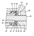
図2に示すように環状部材である環状の第2マスタピストン28の前端面には内外周の中央部分に環状突起33が突設されている。34はシール部材で、シール部材34のベース部35の裏面には環状突起33に嵌合する環状溝36が刻設されている。環状溝36を環状突起33に嵌合させてシール部材34は第2マスタピストン28の端面に当接されている。シール部材34には、外側部材であるシリンダボディ17に穿設されたマスタシリンダ20の内周面に当接する外側リップ37がベース部35の外周縁から軸線方向に突設され、内側部材であるピストンロッド26の外周面に当接する内側リップ38がベース部35の内周縁から軸線方向に突設されている。ベース部35の表面には外側リップ37と内側リップ38との間に環状の分離帯39が形成されている。
【0023】
図2,3に示すように第2マスタピストン28の端面に突設された環状突起33には、頭部40を有する断面円形の係合柱41が複数個、軸線方向に立設されている。シール部材34の分離帯39には係合柱41に係合する複数の係合穴42が穿設され、シール部材34は係合穴42を係合柱41に挿通して頭部40により抜け止めされた状態で環状突起33に環状溝36を嵌合し、第2マスタピストン28の端面に当接して取付けられている。シール部材34を第2マスタピストン28の端面に取付けるために、図4のように第2マスタピストン28の端面の環状突起33に、頭部43を有する断面が屈曲した長円状の係合柱44を複数個、例えば4個、円周上等間隔に軸線方向に立設し、シール部材34の分離帯39に係合柱44に係合する複数の係合長穴を穿設してもよい。
【0024】
第1シリンダ室31はポート46を介して第1ブレーキ系統に連通され、第2シリンダ室32はポート47を介して第2ブレーキ系統に連通されている。第1、第2マスタピストン27,28間には、テテレスコープ機構48により離間距離を規制して互いに接近可能に連結された一対のバネ受け49,50間に予備圧縮された第1圧縮スプリング51が介挿されている。この第1圧縮スプリング51の予備圧縮力が第2マスタピストン28と閉塞部材22との間に介挿された第2圧縮スプリング52の予備圧縮力より大きく設定され、第2マスタピストン28は、非作動時に係合柱41の頭部40前端がバネ受け50の後端面に当接する中立位置に停止される。シリンダボディ17の上端にはリザーバ52がピンで結合して載置固定され、第1、第2マスタピストン27,28が非作動位置にあるときのみ第1、第2シリンダ室31,32に連通してブレーキ液を供給するようになっている。
【0025】
次に、上記実施の形態に係るブレーキ倍力装置の作動について説明する。ブレーキペダル5が踏まれて、入力ロッド6が図1の右方に引っ張られると、制御弁15が作動されて大気が変圧室12に流入され、変圧室12と定圧室11との圧力差によりダイヤフラム10及びピストン14が後退される。ダイヤフラム10の後退に基づいて出力ロッド19、ピストンロッド26が後方に軸動されて第1マスタピストン27が後退され、第1シリンダ室31から液圧がポート46を通って第1ブレーキ系統に供給される。第1シリンダ室31内の液圧が上昇して第2マスタピストン28の後端面に向けて液圧が作用すると、シール部材の34ベース部35が第2マスタピストン28の前端面に押圧され、外側および内側リップ37,38が圧力によりマスタシリンダ20の内周面およびピストンロッド26の外周面にそれぞれ圧接され、マスタシリンダ20の内周面と第2マスタピストン28の外周面との間および第2マスタピストン28の貫通穴内周面とピストンロッド26の外周面との間がシールされる。このとき、分離帯39の両側面に作用する液圧によりベース部35の裏面に刻設された環状溝36の両溝面が第2マスタピストン28の前端面に突設された環状突起33の両側壁に圧接されるので、マスタシリンダ20の内周面と第2マスタピストン28の外周面との間および第2マスタピストン28の内周面とピストンロッド26の外周面との間を夫々シールする断面カップ形状の2個のシール部材を設けたように作動し、外側および内側リップ37,38の一方に作用する力によりシール部材34が半径方向に移動し、他方のリップのシール作用に影響してシール性能を低下することはない。
【0026】
第1マスタピストン27の後方移動により、第1シリンダ室31内の液圧が上昇するために、第2マスタピストン28も第2圧縮スプリング52を圧縮しながら後方移動され、第2シリンダ室32から液圧がポート47を通って第2ブレーキ系統に供給される。第2マスタピストン28は第1、第2シリンダ室31,32が同圧となる位置にバランスされる。
【0027】
ブレーキペダル5が開放されると、制御弁15が切り換わり定圧室11内の負圧が変圧室12に導入され、変圧室12と定圧室11との両室内の圧力差が無くなり、ダイヤフラム10がリターンスプリングのばね力により前方に移動されて原位置に復帰される。第1、第2マスタピストン27,28は第1、第2圧縮スプリング51,52のバネ力により前進され、非作動位置に復帰される。第1マスタピストン27の前進により第1シリンダ室31内の圧力が負圧または無くなっても、第2マスタピストン28前端面に立設した複数の係合柱41にシール部材34の係合穴42を挿通し、係合柱41の頭部40により抜け止めしているので、シール部材34が第2マスタピストン28の前端面から離脱することがない。さらに、第2マスタピストン28は第2圧縮スプリング52により前方に付勢され、係合柱41の頭部40がバネ受け50の後端面に当接されているので、シール部材34が第2マスタピストン28の前端面から離脱することが確実に防止される。
【0028】
上記実施の形態では、ピストンロッド26に第1マスタピストン27を一体に形成したが、第1マスタピストンに穿設した貫通穴にピストンロッドを遊嵌し、ピストンロッドの前端に係合した係合部材を第1マスタピストンの前端面に当接させてピストンロッドを第1マスタピストンに連結し、第1マスタピストンの外周面および内周面とマスタシリンダの内周面およびピストンロッドの外周面とを本発明に係るシール構造30でシールしてもよい。
【0029】
また、第2ピストンに係合柱、シール部材に係合穴を設けなくても、シール部材の環状溝が第2ピストンの環状突起に嵌合し、第2マスタピストンが第2圧縮スプリングにより前方に付勢されて、シール部材が第1圧縮スプリングを挟持するバネ受けの後端面と第2マスタピストンの前端面との間に挟持されるので、第2マスタピストンの前端面に保持されたシール部材が第2マスタピストンから離脱することはない。
【図面の簡単な説明】
【図1】入力ロッド引張り式ブレーキ倍力装置の実施形態の縦断面図。
【図2】本発明に係るシール構造の実施の形態を示す部分断面図。
【図3】第2マスタピストンの前端面を前方から見た図。
【図4】他の実施形態に係る第2マスタピストンの前端面を前方から見た図。
【符号の説明】
1…入力ロッド引張り式ブレーキ倍力装置、2…ブレーキブースタ装置、3…マスタシリンダ装置、6…入力ロッド、7…ブースタ、8…フロントシェル、9…リアシェル、10…ダイヤフラム、11…定圧室、12…変圧室、14…ピストン、15…制御弁体、17…シリンダボディ、19…出力ロッド、20…マスタシリンダ、26…ピストンロッド、27,28…第1、第2マスタピストン、30…シール構造、31,32…第1、第2シリンダ室、33…環状突起、34…シール部材、35…ベース部、36…環状溝、37,38…第1、第2リップ、39…分離帯、40,44…頭部、41,43…係合柱、42…係合穴、49,50…バネ受け、51,52…第1、第2圧縮スプリング。[0001]
TECHNICAL FIELD OF THE INVENTION
The present invention relates to a seal structure for sealing a double fitting portion in which an outer peripheral surface of an annular member is fitted to an inner peripheral surface of an outer member and an outer peripheral surface of an inner member is fitted to the inner peripheral surface of the annular member. is there.
[0002]
[Prior art]
As described in, for example, JP-A-2001-294138, an input rod tension type brake booster has a first master piston fitted into a master cylinder of a master cylinder device and separated from the first master piston. A second master piston is fitted on the rear side, and a piston rod formed integrally with the first master piston penetrates the second master piston and protrudes from the rear end wall of the master cylinder, so that the piston rod is operated by the brake booster device. It has become. In such an input rod tension type brake booster, the second master piston must be fitted in a liquid-tight manner with the master cylinder on the outer peripheral surface and in a fluid-tight manner with the piston rod on the inner peripheral surface.
[0003]
In an input rod tension type brake booster described in Japanese Patent Application Laid-Open No. 56-154357, a brake booster device is mounted at the front end of a master cylinder device, and the brake booster is divided into a constant pressure chamber and a variable pressure chamber by a diaphragm. An input rod for operating a valve mechanism for switching the variable pressure chamber between the atmosphere and the constant pressure chamber to communicate therewith extends through the master piston and the master cylinder and is connected to the brake pedal. Then, the master piston is fitted on the inner peripheral surface of the master cylinder as a seal structure that fits the master cylinder on the outer peripheral surface and a double fitting portion that is fitted with the input rod on the inner peripheral surface in a liquid-tight manner. An outer lip projects axially from the outer peripheral edge of the base portion, and an inner lip that contacts the outer peripheral surface of the input rod projects axially from the inner peripheral edge of the base portion. Is abutted on the back side. As another seal structure, seal members for individually sealing between the outer peripheral surface and the inner peripheral surface of the master piston and the inner peripheral surface of the master cylinder and the outer peripheral surface of the input rod are individually mounted on the master piston.
[0004]
[Patent Document 1]
JP 2001-294138 A (pages 3, 4; FIG. 2)
[0005]
[Patent Document 2]
JP-A-56-154357 (pages 5 and 6, FIGS. 1 and 2)
[0006]
[Problems to be solved by the invention]
In a seal member having only the outer and inner lips protruding from the outer and inner peripheral edges of the base as described above, the movement of the seal member due to the force acting on one of the outer and inner lips affects the other, and May interfere with each other to lower the sealing performance. In addition, when individual sealing members for sealing the double fitting portions are provided on the master piston, there is a problem that the outer diameter or the entire length of the master piston becomes large.
[0007]
The present invention has been made to solve such a conventional problem, and it is an object of the present invention to reduce the size of a seal structure for sealing a double fitting portion without impairing sealing performance.
[0008]
[Means for Solving the Problems]
In order to solve the above-mentioned problem, a structural feature of the invention according to claim 1 is that an outer peripheral surface of an annular member is fitted to an inner peripheral surface of an outer member, and an inner member of the inner member is fitted to an inner peripheral surface of the annular member. In a seal structure for sealing a double fitting portion with which an outer peripheral surface is fitted, an annular projection is provided on an end surface of the annular member at a central portion of the inner and outer circumferences, and the annular projection is provided on a back surface of a base portion of the seal member. An annular groove to be fitted is engraved, the annular groove is fitted to the annular projection, and the seal member contacts the end surface of the annular member, and the seal member contacts the inner peripheral surface of the outer member. An outer lip is axially protruded from an outer peripheral edge of the base portion, an inner lip abutting on an outer peripheral surface of the inner member is axially protruded from an inner peripheral edge of the base portion, and is provided on a surface of the base portion. An annular separator is formed between the outer lip and the inner lip. It is.
[0009]
A structural feature of the invention according to claim 2 is that in claim 1, a plurality of engagement posts having a head are erected from the annular projection and a plurality of engagement holes are engaged with the engagement posts. The annular groove is fitted to the annular projection in a state where the engaging hole is inserted into the engaging column and is prevented from falling off by the head, and the base portion is attached to the annular member. Is attached in contact with the end face.
[0010]
The structural feature of the invention according to claim 3 is that the brake booster is divided into a constant pressure chamber and a variable pressure chamber by a diaphragm, and is operated by an input rod to switch the variable pressure chamber between the atmosphere and the constant pressure chamber to communicate with each other. A valve mechanism is provided on the piston fixed to the diaphragm, the master piston is slidably fitted to a master cylinder drilled in the cylinder body, and the piston rod fitted to the master piston is used to retract the diaphragm. An input rod tension type brake booster that generates a brake fluid pressure by axially moving rearward based on the cylinder body, the master piston, and the piston rod as the outer member, the annular member, and the inner member, respectively; Surface and the outer peripheral surface of the master piston, and the inner peripheral surface and the front of the master piston. Between the outer peripheral surface of the piston rod is that sealed by the seal structure according to claim 1 or 2.
[0011]
The structural feature of the invention according to claim 4 is that the brake booster is divided into a constant pressure chamber and a variable pressure chamber by a diaphragm, and is operated by an input rod to switch the variable pressure chamber between the atmosphere and the constant pressure chamber to communicate with each other. A valve mechanism is provided for the piston fixed to the diaphragm, and the first and second master pistons are slidably fitted to a master cylinder drilled in a cylinder body, and penetrate through the second master piston. An input rod tension type brake booster for generating a brake fluid pressure by axially moving a piston rod connected to a first master piston backward based on the retraction of the diaphragm, wherein the cylinder body, the second master piston, and the piston Rods are respectively the outer member, the annular member and the inner member, and the inner peripheral surface of the master cylinder and the Between the outer peripheral surface of the second master piston, and it was sealed by the sealing structure according to claim 1 or 2 between the outer peripheral surface of the inner peripheral surface of the second master piston and the piston rod.
[0012]
A structural feature of the invention according to claim 5 is that, in claim 4, a first compression spring is interposed between the first and second master pistons with a spring receiver interposed therebetween, and the seal member is provided on a front end surface. The abutting second master piston is pressed against the rear end face of the spring receiver by a second compression spring.
[0013]
[Action and Effect of the Invention]
In the invention according to claim 1 configured as described above, when hydraulic pressure acts on the end surface of the annular member, the base portion of the seal member is pressed against the end surface of the annular member, and the outer and inner lips are hydraulically pressed. The inner peripheral surface of the outer member and the outer peripheral surface of the inner member are pressed against each other, and a seal is formed between the inner peripheral surface of the outer member and the outer peripheral surface of the annular member, and between the inner peripheral surface of the annular member and the outer peripheral surface of the inner member. Is done. At this time, both groove surfaces of the annular groove fitted on the annular protrusion protruded from the end surface of the annular member and engraved on the back surface of the base portion are formed on both side walls of the annular protrusion by liquid pressure acting on both side surfaces of the separation band. Two seal members having a cup-shaped cross section for sealing between the inner peripheral surface of the outer member and the outer peripheral surface of the annular member and between the inner peripheral surface of the annular member and the outer peripheral surface of the inner member, respectively. The sealing member moves in the radial direction due to the force acting on one of the outer and inner lips, and the sealing performance of the other lip can be prevented from deteriorating. Further, since the double fitting portion can be sealed by one seal member, the sealing structure of the double fitting portion can be reduced in size.
[0014]
In the invention according to claim 2 configured as described above, the engagement holes of the seal member are inserted into the plurality of engagement columns erected on the end surface of the annular member, and are prevented from coming off by the heads of the engagement columns. Therefore, even if a negative pressure is applied to the end surface of the annular member, the seal member can be prevented from separating from the annular member.
[0015]
In the invention according to claim 3 configured as described above, when the valve mechanism is operated by the input rod, the atmosphere is introduced into the variable pressure chamber and the diaphragm is retracted, and the piston rod is axially moved rearward based on the retraction of the diaphragm. Activated to generate brake fluid pressure. When hydraulic pressure acts on the end face of the master piston fitted on the piston rod, the base of the seal member is pressed against the end face of the master piston, and the outer and inner lips are hydraulically pressed to the inner circumferential surface of the master cylinder and the piston rod. Each is pressed against the outer peripheral surface. This makes it possible to reduce the sealing structure for sealing between the inner peripheral surface of the master cylinder and the outer peripheral surface of the master piston and between the inner peripheral surface of the master piston and the outer peripheral surface of the piston rod without impairing the sealing performance. Thus, a compact and high-performance input rod tension type brake booster can be provided.
[0016]
In the invention according to claim 4 configured as described above, when the valve mechanism is operated by the input rod, the atmosphere is introduced into the variable pressure chamber, the diaphragm is retracted, and the first master piston passes through the second master piston. Is pivoted rearward based on the retraction of the diaphragm to generate brake fluid pressure. When hydraulic pressure acts on the front end of the second master piston, the base portion of the sealing member is pressed against the front end surface of the second master piston, and the outer and inner lips are hydraulically moved to the inner peripheral surface of the master cylinder and the outer peripheral surface of the piston rod. Respectively. Accordingly, a seal structure for sealing between the inner peripheral surface of the master cylinder and the outer peripheral surface of the second master piston and between the inner peripheral surface of the second master piston and the outer peripheral surface of the piston rod can be provided without impairing the sealing performance. A small, high-performance tandem-type input rod tension type brake booster can be provided.
[0017]
In the invention according to claim 5 configured as described above, the second master piston is urged forward by the second compression spring and pressed against the rear end face of the spring receiver that clamps the first compression spring. The seal member abutting on the front end surface of the second master piston does not come off the second master piston.
[0018]
Embodiment
Hereinafter, an embodiment in which a seal structure according to the present invention is applied to an input rod tension type brake booster will be described with reference to the drawings. In FIG. 1, reference numeral 1 denotes an input rod tension type booster, which is configured by connecting a brake booster device 2 and a master cylinder device 3. The input rod pulling type booster 1 is fixed to a dashboard 4 of a vehicle that separates an engine room and a vehicle compartment, and an input rod 6 is pulled rearward by a brake pedal 5 mounted on the vehicle compartment side of the dashboard 4. As a result, the brake fluid pressure is sent from the master cylinder device 3 to a wheel cylinder (not shown).
[0019]
The brake booster device 2 has a front shell 8 and a rear shell 9 forming a booster 7, and the inside of the booster 7 is divided into a constant pressure chamber 11 and a variable pressure chamber 12 by a diaphragm 10 sandwiched between the shells 8, 9. Have been. A negative pressure introducing pipe 13 is attached to the rear shell 9, and the constant pressure chamber 11 is connected to an intake manifold of the engine through the negative pressure introducing pipe 13 and is maintained at a negative pressure. A piston 14 is fixed to the diaphragm 10, and a valve mechanism 15 that is operated by the input rod 6 to switch the variable pressure chamber 12 between the atmosphere and the constant pressure chamber 11 to communicate with each other and move the diaphragm 10 forward and backward is built in the piston 14. The front shell 8 and the rear shell 9 are connected by two tie rods 16 on the circumference. In the brake booster device 2, the front end surface of the front shell 8 is in contact with the rear end surface of a flange portion 17a formed on the cylinder body 17 of the master cylinder device 3, and the front end portion 16a of the tie rod 16 is drilled in the flange portion 17a. The nut 18 is screwed into a male screw engraved on the front end 16 b and is connected to the master cylinder device 3.
[0020]
A cylinder 20 a forming the master cylinder 20 and a mounting hole 21 are coaxially formed in the cylinder body 17, and a small-diameter end portion of a cup-shaped closing member 22 is sealed and fitted into the mounting hole 21, and a front end face of the closing member 22 is formed. A ring 23 and a seal member 24 are interposed between the mounting member 21 and the shoulder of the mounting hole 21. The closing member 22 is fixed to the rear end of the cylinder body 17 by screwing an outer peripheral screw portion into the mounting hole 21. The output rod 19 of the brake booster device 2 penetrates the rear end bottom of the closing member 22 by being sealed by a seal member 25, and extends forward as a piston rod 26 in the master cylinder 20. A cylinder 20b serving as a rear end of the master cylinder 20 is formed at the front end small diameter portion of the closing member 22.
[0021]
First and second master pistons 27 and 28 are slidably fitted to the master cylinder 20. The first master piston 27 is formed integrally with the front end of the piston rod 26, and a gap between the outer peripheral surface and the inner peripheral surface of the master cylinder 20 is formed by a seal member 29 fitted in a concave groove formed in the first master piston 27. Sealed. The annular second master piston 28 is loosely fitted to the piston rod 26 with a through hole, and is formed between the outer peripheral surface of the second master piston 28 and the inner peripheral surface of the master cylinder 20 and the inner peripheral surface of the through hole of the second master piston 28. The space between the piston rod 26 and the outer peripheral surface is sealed by a seal structure 30 according to the present invention, and the master cylinder 20 is partitioned into first and second cylinder chambers 31 and 32.
[0022]
As shown in FIG. 2, an annular projection 33 is provided on the front end face of the annular second master piston 28, which is an annular member, at the center of the inner and outer circumferences. Reference numeral 34 denotes a seal member, and an annular groove 36 that fits into the annular protrusion 33 is formed on the back surface of the base 35 of the seal member 34. The seal member 34 is in contact with the end surface of the second master piston 28 by fitting the annular groove 36 into the annular protrusion 33. An outer lip 37 abutting on the inner peripheral surface of the master cylinder 20 pierced in the cylinder body 17 as an outer member is provided on the seal member 34 so as to protrude in the axial direction from the outer peripheral edge of the base portion 35 and is an inner member. An inner lip 38 abutting on the outer peripheral surface of the piston rod 26 protrudes from the inner peripheral edge of the base portion 35 in the axial direction. An annular separation band 39 is formed between the outer lip 37 and the inner lip 38 on the surface of the base portion 35.
[0023]
As shown in FIGS. 2 and 3, a plurality of engaging pillars 41 having a circular cross section having a head 40 are provided upright in an axial direction on an annular projection 33 protruding from an end surface of the second master piston 28. . A plurality of engagement holes 42 are formed in the separation band 39 of the seal member 34 so as to engage with the engagement pillars 41. In the stopped state, the annular groove 36 is fitted into the annular projection 33, and is mounted in contact with the end surface of the second master piston 28. In order to attach the seal member 34 to the end face of the second master piston 28, an elliptical engagement column having a head 43 and having a bent cross section is provided on the annular projection 33 on the end face of the second master piston 28 as shown in FIG. Even if a plurality of, for example, four, 44 are erected in the axial direction at equal intervals on the circumference, and a plurality of elongated holes for engaging with the engaging columns 44 are formed in the separation band 39 of the seal member 34. Good.
[0024]
The first cylinder chamber 31 is connected to a first brake system via a port 46, and the second cylinder chamber 32 is connected to a second brake system via a port 47. A first compression spring 51 pre-compressed between a pair of spring receivers 49 and 50 connected between the first and second master pistons 27 and 28 such that the distance between the first and second master pistons 27 and 28 is restricted by a telescopic mechanism 48 so that they can approach each other. Is inserted. The preliminary compression force of the first compression spring 51 is set to be larger than the preliminary compression force of the second compression spring 52 inserted between the second master piston 28 and the closing member 22, and the second master piston 28 During operation, the front end of the head 40 of the engaging column 41 is stopped at a neutral position where the front end of the head abuts against the rear end surface of the spring receiver 50. A reservoir 52 is mounted and fixed to the upper end of the cylinder body 17 by a pin, and communicates with the first and second cylinder chambers 31 and 32 only when the first and second master pistons 27 and 28 are at the inoperative position. And supply the brake fluid.
[0025]
Next, the operation of the brake booster according to the above embodiment will be described. When the brake pedal 5 is depressed and the input rod 6 is pulled rightward in FIG. 1, the control valve 15 is actuated, the atmosphere flows into the variable pressure chamber 12, and the pressure difference between the variable pressure chamber 12 and the constant pressure chamber 11 is increased. The diaphragm 10 and the piston 14 are retracted. Based on the retraction of the diaphragm 10, the output rod 19 and the piston rod 26 are axially moved rearward, the first master piston 27 is retracted, and the hydraulic pressure is supplied from the first cylinder chamber 31 to the first brake system through the port 46. Is done. When the hydraulic pressure in the first cylinder chamber 31 increases and the hydraulic pressure acts on the rear end surface of the second master piston 28, the base portion 35 of the seal member is pressed against the front end surface of the second master piston 28, The outer and inner lips 37, 38 are pressed against the inner peripheral surface of the master cylinder 20 and the outer peripheral surface of the piston rod 26 by pressure, respectively, so that the outer and inner lips 37, 38 are located between the inner peripheral surface of the master cylinder 20 and the outer peripheral surface of the second master piston 28. The space between the inner peripheral surface of the through hole of the second master piston 28 and the outer peripheral surface of the piston rod 26 is sealed. At this time, both groove surfaces of the annular groove 36 engraved on the back surface of the base portion 35 by the hydraulic pressure acting on both side surfaces of the separation band 39 are formed by the annular projection 33 protruding from the front end surface of the second master piston 28. Since it is pressed against both side walls, it seals between the inner peripheral surface of the master cylinder 20 and the outer peripheral surface of the second master piston 28 and between the inner peripheral surface of the second master piston 28 and the outer peripheral surface of the piston rod 26, respectively. It operates as if two sealing members having a cup shape in cross section are provided, and the sealing member 34 moves in the radial direction by a force acting on one of the outer and inner lips 37, 38, which affects the sealing action of the other lip. Therefore, the sealing performance is not reduced.
[0026]
Since the hydraulic pressure in the first cylinder chamber 31 increases due to the backward movement of the first master piston 27, the second master piston 28 is also moved backward while compressing the second compression spring 52. Hydraulic pressure is supplied through port 47 to the second brake system. The second master piston 28 is balanced to a position where the first and second cylinder chambers 31, 32 have the same pressure.
[0027]
When the brake pedal 5 is released, the control valve 15 is switched, and the negative pressure in the constant pressure chamber 11 is introduced into the variable pressure chamber 12, and the pressure difference between both the variable pressure chamber 12 and the constant pressure chamber 11 disappears, and the diaphragm 10 is moved. It is moved forward by the spring force of the return spring and returns to its original position. The first and second master pistons 27 and 28 are advanced by the spring force of the first and second compression springs 51 and 52, and return to the inoperative position. Even if the pressure in the first cylinder chamber 31 becomes negative or disappears due to the advance of the first master piston 27, the plurality of engagement columns 41 erected on the front end face of the second master piston 28 engage the engagement holes 42 of the seal member 34. Is inserted and is stopped by the head 40 of the engaging column 41, so that the seal member 34 does not come off from the front end surface of the second master piston 28. Further, the second master piston 28 is urged forward by the second compression spring 52, and the head 40 of the engaging post 41 is in contact with the rear end surface of the spring receiver 50, so that the seal member 34 is Detachment from the front end surface of the piston 28 is reliably prevented.
[0028]
In the above embodiment, the first master piston 27 is formed integrally with the piston rod 26, but the piston rod is loosely fitted into a through hole formed in the first master piston and engaged with the front end of the piston rod. The member is brought into contact with the front end surface of the first master piston to connect the piston rod to the first master piston, and the outer peripheral surface and inner peripheral surface of the first master piston, the inner peripheral surface of the master cylinder, and the outer peripheral surface of the piston rod are connected to each other. May be sealed by the seal structure 30 according to the present invention.
[0029]
Further, even if the second piston is not provided with an engagement column and the seal member is not provided with an engagement hole, the annular groove of the seal member is fitted into the annular projection of the second piston, and the second master piston is moved forward by the second compression spring. And the seal member is sandwiched between the rear end surface of the spring receiver that sandwiches the first compression spring and the front end surface of the second master piston, so that the seal held on the front end surface of the second master piston The member does not separate from the second master piston.
[Brief description of the drawings]
FIG. 1 is a longitudinal sectional view of an embodiment of an input rod tension type brake booster.
FIG. 2 is a partial sectional view showing an embodiment of a seal structure according to the present invention.
FIG. 3 is a view of a front end surface of a second master piston as viewed from the front.
FIG. 4 is a view of a front end surface of a second master piston according to another embodiment as viewed from the front.
[Explanation of symbols]
DESCRIPTION OF SYMBOLS 1 ... Input rod pulling type brake booster, 2 ... Brake booster device, 3 ... Master cylinder device, 6 ... Input rod, 7 ... Booster, 8 ... Front shell, 9 ... Rear shell, 10 ... Diaphragm, 11 ... Constant pressure chamber, 12 ... variable pressure chamber, 14 ... piston, 15 ... control valve body, 17 ... cylinder body, 19 ... output rod, 20 ... master cylinder, 26 ... piston rod, 27, 28 ... first and second master piston, 30 ... seal Structure, 31, 32: first and second cylinder chambers, 33: annular projection, 34: sealing member, 35: base portion, 36: annular groove, 37, 38: first and second lip, 39: separation band, 40, 44 ... head, 41, 43 ... engaging column, 42 ... engaging hole, 49, 50 ... spring receiver, 51, 52 ... first and second compression springs.