【0001】
【発明の属する技術分野】
本発明は、遊技に用いられる図柄列の変動をマイクロコンピュータなどにより制御するスロットマシン、パチスロ機、パチンコ機を含む遊技機に関するものである。
【0002】
【従来の技術】
従来のパチスロ機(遊技機に含まれる)は、表示窓内に図柄列を変動表示する回転リールを複数配列して構成した機械的な変動表示装置、あるいは回転リール上の図柄を画面に表示する電気的な変動表示装置を具備している。これは、スタートレバーの操作で、マイクロコンピュータなどが変動表示装置を駆動制御して各回転リールを回転させることにより、図柄列が変動表示され、さらに所定時間後に自動停止させるか、あるいは停止ボタンの操作で各回転リールを順次停止させるものである。このとき、表示窓内に現れた各回転リールの図柄が特定の組合せ(入賞図柄)になった場合に、メダル又はコインなどの遊技媒体を払出すことになる。
【0003】
現在主流の機種においては、有効化された入賞ライン(以下「有効ライン」という)に沿って所定の図柄の組合せが並び、入賞が成立してメダル、コイン等が払出されるためには、内部的な抽選処理(以下「内部抽選」という)により役に当選(以下「内部当選」という)し、かつその内部当選した役(以下「内部当選役」という)の入賞成立を示す図柄組合せを有効ラインに停止できるタイミングで遊技者が停止操作を行うことが要求される。つまり、内部当選したとしても、遊技者の停止操作のタイミングがずれると入賞を成立させることができない。すなわち、停止操作をタイミングよく行う技術(いわゆる「目押し」といわれる技術)が要求されるパチスロ機が現在の主流である。
【0004】
そこで、「目押し」ができない遊技者についても、遊技に対する興味を持続させるために、所定の条件を満たした場合に限り、遊技者の停止操作を誘導又は報知して入賞させる特別の期間を設定している機種がある。
【0005】
このような従来のパチスロ機は、一般遊技状態(ここでは、BB遊技中でない状態)において、ボーナス以外の所定の小役に内部当選したとき、回転リールごとに設けられた停止ボタンの押順(停止順序)が報知されて、確実に入賞が成立するという期間(以下「スーパータイム」という)を設け、この「スーパータイム」の発生及び終了条件をそれぞれ設定している。また、「スーパータイム」の発生を報知するための演出画像を予め用意し、液晶表示画面に表示している。なお、演出及び報知手段として液晶表示装置の他に演出用のリール、模型などの動作物、音、光、LEDドットマトリクスなどを用いることが示唆されている(例えば、特許文献1参照)。
【0006】
【特許文献1】
特開2002‐253738号公報(図6、図17など)
【0007】
【発明が解決しようとする課題】
しかしながら、上記従来の遊技機では、遊技者にとって有利な遊技期間(「スーパータイム」を含む)を所定の条件で延長することについては配慮がなされておらず、遊技者の興味を持続させるためには、さらに改善の余地がある。
【0008】
本発明は、遊技者にとって有利な遊技期間の延長を示唆して遊技者の興味を持続させることが可能な遊技機を提供することを目的としている。
【0009】
【課題を解決するための手段】
本発明の遊技機は、上記問題を解決するために、遊技のための操作を行う操作手段(例えば、スタートレバー6、停止ボタン7L、7C、7R)と、前記操作手段の操作により、遊技に用いる図柄列を変動表示する変動表示手段(例えば、リール3L、3C、3R)と、前記操作手段の操作により、乱数を用いて入賞態様を決定するための内部抽選を行う内部抽選手段(例えば、主制御回路71)と、前記操作手段の操作態様、前記内部抽選手段の抽選結果及び遊技状態により、前記変動表示手段を停止制御する停止制御手段(例えば、主制御回路71)と、第1の条件を満足した場合(例えば、図28のST2004の“NO”又は図18のST32の“YES”)に、所定の遊技状態に移行する遊技状態移行手段(例えば、主制御回路71)と、前記所定の遊技状態にあって、所定の入賞態様(例えば、スーパーBBとなるBB)が成立した場合、前記所定の入賞態様の遊技中に、前記変動表示手段の図柄列の停止態様が入賞成立を示すように、前記操作手段の操作態様を報知する報知手段(例えば、副制御回路72、液晶表示装置5)と、前記所定の遊技状態にあって、第2の条件を満足した場合(例えば、図28のST2004の“YES”)に、前記所定の遊技状態にある期間を延長する期間延長手段(例えば、主制御回路71)とを備え、第1の条件及び第2の条件には、前記停止制御手段が所定の態様(例えば、リールの「滑り」)の停止制御を行うこと(例えば、図28のST2001の“YES”)が含まれることを特徴としている。
【0010】
このような構成によれば、遊技者にとって有利なチャンスゾーン(所定の遊技状態に含まれる)にあるとき、例えば、チェリーなどの小役の内部当選よりも発生頻度が高いリールの「滑り」などの停止制御を契機としたチャンスゾーン突入抽選に当選するという条件(第2の条件に含まれる)を満足することによって、前記チャンスゾーンの期間をさらに延長(上乗せ)するので、遊技者の遊技に対する興味を持続させることができる。さらに、リールの「滑り」などの停止態様によって前記チャンスゾーンの発生や期間延長の機会が示唆されるので、遊技者は「目押し」などの操作によって積極的に遊技することとなる。
【0011】
また、本発明の遊技機は、遊技のための操作を行う操作手段(例えば、スタートレバー6、停止ボタン7L、7C、7R)と、前記操作手段の操作により、遊技に用いる複数の図柄列を変動表示する変動表示手段(例えば、リール3L、3C、3R)と、前記操作手段の操作により、乱数を用いて入賞態様を決定するための内部抽選を行う内部抽選手段(例えば、主制御回路71)と、前記操作手段の操作態様、前記内部抽選手段の抽選結果及び遊技状態により、前記変動表示手段を停止制御する停止制御手段(例えば、主制御回路71)と、第1の入賞態様(例えば、BB)が成立可能な回数の情報、及び第2の入賞態様(例えば、RB)が成立可能な回数の情報を記憶する回数情報記憶手段(例えば、主制御回路71)と、前記回数情報記憶手段に記憶された回数が1以上であり、かつ所定の条件を満足した場合(例えば、図23のST1504の“YES”)に第1の入賞態様を成立させる入賞成立手段(例えば、主制御回路71)とを備えた遊技機であって、第1の条件を満足した場合(例えば、図28のST2004の“NO”又は図18のST32の“YES”)に、所定の遊技状態に移行する遊技状態移行手段(例えば、主制御回路71)と、前記所定の遊技状態にあり、かつ第2の条件を満足した場合(例えば、図28のST2004の“YES”)に、前記所定の遊技状態にある期間を延長する期間延長手段(例えば、主制御回路71)と、前記所定の遊技状態にあって、前記入賞成立手段が第1の入賞態様を成立させた場合に、第1の入賞態様の遊技中、前記変動表示手段の図柄列の停止態様が入賞成立を示すように、前記操作手段の操作態様を報知する報知手段(例えば、液晶表示装置5、副制御回路72)とを備え、第1の条件及び第2の条件には、前記停止制御手段が所定の態様(例えば、リールの「滑り」)の停止制御を行うこと(例えば、図28のST2001の“YES”)が含まれることを特徴としている。
【0012】
このような構成によれば、いわゆる「ストック機」において、例えば、BB(第1の入賞態様に含まれる)が成立可能な回数の情報を回数情報記憶手段に記憶しながら、その入賞成立を許可しない高確率再遊技状態において、遊技者にとって有利なチャンスゾーン(所定の遊技状態に含まれる)にあるとき、例えば、チェリーなどの小役の内部当選よりも発生頻度が高い「滑り」などの停止制御を契機としたチャンスゾーン突入抽選に当選するという条件(第2の条件に含まれる)を満足することによって、前記チャンスゾーンの期間を延長(上乗せ)するので、遊技者は、成立可能なBBがストック(持ち越し)された状態にあっても、遊技に対する興味を持続させることができる。さらに、リールの「滑り」などの停止態様によって前記チャンスゾーンの発生や期間延長の機会が示唆されるので、遊技者は「目押し」などの操作によって積極的に遊技することとなる。
【0013】
また、本発明の遊技機は、前記所定の遊技状態(例えば、チャンスゾーン)に移行するか否かを決定するために乱数を用いて移行抽選(例えば、チャンスゾーン突入抽選(図28のST2002))を行う移行抽選手段(例えば、主制御回路71)を備え、第1の条件は、第1の入賞態様(例えば、BB)の遊技が終了したこと(例えば、図18のST32の“YES”)、又は前記停止制御手段が所定の態様(例えば、リールの「滑り」)の停止制御を行い(例えば、図28のST2001の“YES”)、さらに前記移行抽選に当選したこと(例えば、図28のST2004の“NO”)によって満足され、第2の条件は、前記停止制御手段が所定の態様の停止制御を行い、さらに前記移行抽選に当選したこと(例えば、図28のST2004の“YES”)によって満足されることを特徴としている。
【0014】
このような構成によれば、遊技者にとって有利なチャンスゾーン(所定の遊技状態に含まれる)中に、例えば、チェリーなどの小役の内部当選よりも発生頻度が高い「滑り」などの停止制御が発生し、かつチャンスゾーン突入抽選(移行抽選に含まれる)に当選したことにより、前記チャンスゾーンが延長されるので、BB(第1の入賞態様に含まれる)がストック(持ち越し)された状態にあっても、遊技者は、前記チャンスゾーンの期間が延長(上乗せ)される機会を示唆されて、遊技に対する興味を持続させることができる。また、前記チャンスゾーンに移行する機会が2回あることも、遊技に対する興味を持続させるのに好適である。
【0015】
また、本発明の遊技機は、前記所定の条件及び前記所定の遊技状態(例えば、チャンスゾーン)の終了条件には、第1の入賞態様及び第2の入賞態様の成立を許可しない不許可遊技状態(例えば、「高確率再遊技中」)を解除するための抽選(例えば、ストック解除抽選)に当選し(例えば、図23のST1504の“YES”)、第1の入賞態様に振り分けられること(例えば、図23のST1505)が含まれることを特徴としている。
【0016】
このような構成によれば、例えば、ストック解除当選によってチャンスゾーン(所定の遊技状態に含まれる)は終了するが、ここで第1の入賞態様として成立したBB(スーパーBBとなるBB)が終了すること(第1の条件に含まれる)により、再びチャンスゾーンが発生するので、遊技者にとって有利なチャンスゾーンとなる機会が増すことになる。よって、遊技者は遊技に対する興味を持続させることができる。
【0017】
【発明の実施の形態】
以下、本発明の好ましい実施形態を図面に基づいて説明する。
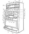
図1は、本発明に係る遊技機を「パチスロ機」に適用した実施の一形態を示している。「パチスロ機」は、コイン、メダル、遊技球又はトークンなどの他、遊技者に付与された、もしくは付与される遊技価値の情報を記憶したカードなどの遊技媒体を用いて遊技する遊技機であるが、ここではメダルを用いる場合を示す。
【0018】
遊技機1の全体を形成しているキャビネット2の正面には、略垂直面としてのパネル表示部2aが形成され、その中央には縦長矩形の表示窓4L、4C、4Rが設けられる。表示窓4L、4C、4Rには、入賞ラインとして水平方向にトップライン8b、センターライン8c及びボトムライン8d、斜め方向にクロスダウンライン8a及びクロスアップライン8eが設けられている。これらの入賞ラインは、後述の1‐BETスイッチ11、2‐BETスイッチ12、最大BETスイッチ13を操作すること、或いはメダル投入口22にメダルを投入することにより、それぞれ1本、3本、5本が有効化される。どの入賞ラインが有効化されたかは、後で説明するBETランプ9a、9b、9cの点灯で表示される。
【0019】
キャビネット2の内部には、各々の外周面に複数種類の図柄によって構成きれる図柄列が描かれた3個のリール3L、3C、3Rが回転自在に横一列に設けられている。各リールの図柄は表示窓4L、4C、4Rを通して観察できるようになっている。各リールは、定速(例えば80回転/分)で回転する。
【0020】
表示窓4L、4C、4Rの左側には、1‐BETランプ9a、2‐BETランプ9b、最大BETランプ9c、クレジット表示部19が設けられる。1‐BETランプ9a、2‐BETランプ9b及び最大BETランプ9cは、一つのゲームを行うために設けられたメダルの数(以下「BET数」という)に応じて点灯する。ここでは、一つのゲームは、全てのリールが停止したときに終了する。1‐BETランプ9aは、BET数が“1”で1本の入賞ラインが有効化されたときに点灯する。2‐BETランプ9bは、BET数が“2”で3本の入賞ラインが有効化されたときに点灯する。最大BETランプ9cは、BET数が “3”で全て(5本)の入賞ラインが有効化されたときに点灯する。クレジット表示部19は、7セグメントLEDから成り、貯留されているメダルの枚数を表示する。
【0021】
表示窓4L、4C、4Rの右側には、当り表示ランプ(いわゆるWINランプ)17及び払出表示部18が設けられる。当り表示ランプ17は、所定の役、例えば「ビッグボーナス(以下、BBと記す)」又は「レギュラーボーナス(以下、RBと記す)」の入賞成立が実現可能となった後、BB又はRBの入賞が成立するまでの間、点灯する。ここで、BB及びRBを総称して、以下単に「ボーナス」という。払出表示部18は、7セグメントLEDから成り、入賞成立時のメダルの払出枚数を表示する。
【0022】
パネル表示部2aの右側上部には、ボーナス遊技情報表示部20が設けられている。ボーナス遊技情報表示部20は、7セグメントLEDから成り、後で説明するBB一般遊技状態におけるゲームの回数などを表示する。表示窓4L、4C、4Rの下方には略水平面の台座部10が形成され、その台座部10と表示窓4L、4C、4Rとの間には液晶表示装置5が設けられている。この液晶表示装置5の表示画面5aには、遊技に関する情報(後述の押順報知に関する情報を含む)などが表示される。
【0023】
液晶表示装置5の右側にはメダル投入ロ22が設けられ、液晶表示装置5の左側には、1‐BETスイッチ11、2‐BETスイッチ12、及び最大BETスイッチ13が設けられる。1‐BETスイッチ11は、1回の押し操作により、クレジットされているメダルのうちの1枚がゲームに賭けられ、2‐BETスイッチ12は、1回の押し操作により、クレジットされているメダルのうちの2枚がゲームに賭けられ、最大BETスイッチ13は、1回のゲームに賭けることが可能な最大枚数のメダルが賭けられる。これらのBETスイッチを操作することで、所定の入賞ラインが有効化される。
【0024】
台座部10の前面部の左寄りには、遊技者がゲームで獲得したメダルのクレジット/払出しを押しボタン操作で切り換えるC/Pスイッチ14が設けられている。このC/Pスイッチ14の切り換えにより、正面下部のメダル払出口15からメダルが払出され、払出されたメダルはメダル受け部16に溜められる。C/Pスイッチ14の右側には、遊技者の操作によりリール3L、3C、3Rを回転させ、表示窓4L、4C、4R内での図柄の変動表示を開始するためのスタートレバー6が所定の角度範囲で回動自在に取り付けられている。
【0025】
キャビネット2の上方の左右には、スピーカ21L、21Rが設けられ、その2台のスピーカ21L、21Rの間には、入賞図柄の組合せ及びメダルの配当枚数などを表示する配当表パネル23が設けられている。台座部10の前面部中央で、液晶表示装置5の下方位置には、3個のリール3L、3C、3Rの回転をそれぞれ停止させるための3個の停止ボタン7L、7C、7Rが設けられている。
【0026】
図2は、各リール3L、3C、3Rに表された複数種類の図柄が21個配列された図柄列を示している。各図柄には“00”〜“20”のコードナンバーが付され、データテーブルとして後述するROM32(図3に示す)に格納されている。各リール3L、3C、3R上には、“ドンちゃん(図柄91)”、“七(図柄92)”、“HANABI(図柄93)”、“大山(図柄94)”、“三尺玉(図柄95)”、“扇子(図柄96)”及び“チェリー(図柄97)”の図柄で構成される図柄列が表わされている。各リール3L、3C、3Rは、図柄列が図2の矢印方向に移動するように回転駆動される。
【0027】
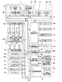
図3は、遊技機1における遊技処理動作を制御する主制御回路71(内部抽選手段、移行抽選手段などに含まれる)と、主制御回路71に電気的に接続する周辺装置(アクチュエ一タ)と、主制御回路71から送信される制御指令に基づいて液晶表示装置5及びスピーカ21L、21Rを制御する副制御回路72とを含む回路構成を示す。
【0028】
主制御回路71は、回路基板上に配置されたマイクロコンピュータ30を主たる構成要素とし、これに乱数サンプリングのための回路を加えて構成されている。マイクロコンピュータ30は、予め設定されたプログラムに従って制御動作を行うCPU31と、記憶手段であるROM32及びRAM33を含む。
【0029】
CPU31には、基準クロックパルスを発生するクロックパルス発生回路34及び分周器35と、サンプリングされる乱数を発生する乱数発生器36及びサンプリング回路37とが接続されている。なお、乱数サンプリングのための手段として、マイクロコンピュータ30内で、すなわちCPU31の操作プログラム上で乱数サンプリングを実行するように構成してもよい。その場合、乱数発生器36及びサンプリング回路37は省略可能であり、或いは、乱数サンプリング動作のバックアップ用として残しておくことも可能である。また、CPU31には、ボーナスのストック数をカウントするためのストック数カウンタ、後述するチャンスゾーンゲーム数をカウントするためのチャンスゾーンゲーム数カウンタなどが設けられている。
【0030】
マイクロコンピュータ30のROM32には、スタートレバー6を操作(スタート操作)する毎に行われる乱数サンプリングの判定に用いられる確率抽選テーブル(後述の図10を含む)、停止ボタンの操作に応じてリールの停止態様を決定するための停止テーブル群(後述の図12〜図14を含む)、副制御回路72へ送信するための各種制御指令(コマンド)などが格納されている。このコマンドには、「待機画面コマンド」、「全リール停止コマンド」などがある。これらのコマンドについては後で説明する。なお、副制御回路72が主制御回路71ヘコマンド、情報などを入力することはなく、主制御回路71から副制御回路72への一方向で通信が行われる。
【0031】
RAM33には、種々の情報が格納される。例えば、後述の高確率再遊技フラグ、ヒットリクエストフラグ(以下「ボーナスフラグ」ともいう)、チャンスゾーン中フラグ、BBストック数の情報、RBストック数、チャンスゾーンゲーム数の情報などが格納されている。
【0032】
図3の回路において、マイクロコンピュータ30からの制御信号により動作が制御される、主要なアクチュエータとしては、各種ランプ(1‐BETランプ9a、2‐BETランプ9b、最大BETランプ9c、当り表示ランプ17)と、各種表示部(払出表示部18、クレジット表示部19、ボーナス遊技情報表示部20)と、メダルを収納し、ホッパー駆動回路41の命令により所定枚数のメダルを払出す遊技価値付与手段としてのホッパー(払出しのための駆動部を含む)40と、リール3L、3C、3Rを回転駆動するステッピングモータ49L、49C、49Rとがある。
【0033】
さらに、ステッピングモータ49L、49C、49Rを駆動制御するモータ駆動回路39、ホッパー40を駆動制御するホッパー駆動回路41、各種ランプを駆動制御するランプ駆動回路46、及び各種表示部を駆動制御する表示部駆動回路48がI/Oポート38を介してCPU31の出力部に接続されている。これらの駆動回路39、41、46、48は、それぞれCPU31から出力される駆動指令などの制御信号を受けて、各アクチュエータの動作を制御する。
【0034】
また、マイクロコンピュータ30が制御指令を発生するために必要な入力信号を発生する、主な入力信号発生手段としては、スタートスイッチ6S、1‐BETスイッチ11、2‐BETスイッチ12、最大BETスイッチ13、C/Pスイッチ14、投入メダルセンサ22S、リール停止信号回路46、リール位置検出回路50、払出完了信号回路51がある。これらも、I/Oポート38を介してCPU31に接続されている。
【0035】
スタートスイッチ6Sは、スタートレバー6の操作を検出する。投入メダルセンサ22Sは、メダル投入口22に投入されたメダルを検出する。リール停止信号回路46は、各停止ボタン7L、7C、7Rの操作に応じて停止信号を発生する。リール位置検出回路50は、リール回転センサからのパルス信号を受けて各リール3L、3C、3Rの位置を検出するための信号をCPU31へ供給する。払出完了信号回路51は、メダル検出部40Sの計数値(ホッパー40から払出されたメダルの枚数)が指定された枚数データに達した時、メダル払出完了を検知するための信号を発生する。
【0036】
図3の回路において、乱数発生器36は、一定の数値範囲に属する乱数を発生し、サンプリング回路37は、スタートレバー6が操作された後の適宜のタイミングで1個の乱数をサンプリングする。こうしてサンプリングされた乱数及びROM32内に格納されている確率抽選テーブル(後述する図10の確率抽選テーブルを含む)に基づいて、内部当選役が決定される。
【0037】
リール3L、3C、3Rの回転が開始された後、ステッピングモータ49L、49C、49Rの各々に供給される駆動パルスの数が計数され、その計数値はRAM33の所定エリアに書き込まれる。リール3L、3C、3Rからは1回転毎にリセットパルスが得られ、これらのパルスはリール位置検出回路50を介してCPU31に入力される。こうして得られたリセットパルスにより、RAM33で計数されている駆動パルスの計数値が“0”にクリアされる。これにより、RAM33内には、各リール3L、3C、3Rについて一回転の範囲内における回転位置に対応した計数値が格納される。
【0038】
また、リール3L、3C、3Rの回転位置とリール外周面上に描かれた図柄とを対応づけるために、図柄テーブル(図示せず)が、ROM32内に格納されている。この図柄テーブルでは、前述したリセットパルスが発生する回転位置を基準として、各リール3L、3C、3Rの一定の回転ピッチ毎に順次付与されるコードナンバーと、それぞれのコードナンバー毎に対応して設けられた図柄を示す図柄コードとが対応づけられている。
【0039】
さらに、ROM32内には、入賞図柄組合せテーブル(図示せず)が格納されている。この入賞図柄組合せテーブルでは、入賞となる図柄の組合せと、入賞のメダル配当枚数と、その入賞を表わす入賞判定コードとが対応づけられている。前記入賞図柄組合せテーブルは、左のリール3L、中央のリール3C、右のリール3Rの停止制御時、及び全リール停止後の入賞確認を行うときに参照される。
【0040】
前記乱数サンプリングに基づく抽選処理(確率抽選処理)により内部当選した場合に、CPU31は、遊技者が停止ボタン7L、7C、7Rを操作したタイミンクでリール停止信号回路46から送られる操作信号、及び選択された停止テーブル(後述の図12〜図14を含む)に基づいて、リール3L、3C、3Rを停止制御する信号をモータ駆動回路39に送る。
【0041】
ここで、内部当選した役の入賞成立を示す停止態様となった場合に、CPU31は、払出し指令信号をホッパー駆動回路41に供給してホッパー40から所定個数のメダルの払出しを行う。その際、メダル検出部40Sは、ホッパー40から払出されるメダルの枚数を計数し、その計数値が指定された数に達した時に、メダル払出完了信号がCPU31に入力される。これにより、CPU31は、ホッパー駆動回路41を介してホッパー40の駆動を停止し、「メダル払出処理」を終了する。
【0042】
副制御回路72は、主制御回路71からの制御指令(コマンド)及びメダルセンサ24Sからのメダル検出信号に基づいて液晶表示装置5の表示制御、当り表示ランプ(WINランプ)17の制御、スピーカ21L,21Rからの音の出力制御を行う。また、副制御回路72は、主制御回路71を構成する回路基板とは別の回路基板上に構成され、マイクロコンピュータを主たる構成要素とし、液晶表示装置5の表示制御手段としての画像制御回路、スピーカ21L、21Rにより出される音を制御する音源、増幅器としてのパワーアンプで構成されている。特に、副制御回路72は、後述する「チャンスゾーン」中に入賞成立したBB(以下「スーパーBB」ともいう)の特典である押順報知を行うために、液晶表示装置5の表示制御を行うものである。
【0043】
次に、図4を参照して、所定の遊技状態における入賞図柄組合せに対応する役(入賞態様に含まれる)及び払出枚数を説明する。本実施形態では、BB(第1の入賞態様に含まれる)、RB(第2の入賞態様に含まれる)を含む複数種類の入賞態様を有する。BB又はスーパーBBの入賞は、内部当選状態において“七‐七‐七”又は“ドンちゃん‐ドンちゃん‐ドンちゃん”が有効ラインに沿って並ぶことにより成立する。BB又はスーパーBBの入賞が成立した後、BB一般遊技状態に移行する。RBの入賞は、内部当選状態において“HANABI‐HANABI‐HANABI”が有効ラインに沿って並ぶこと、又はBB一般遊技状態において“扇子‐扇子‐扇子”が並ぶことにより成立する。BB一般遊技状態においてRBの入賞が成立することを、一般に「ジャックイン(JAC IN)」という。RBの入賞が成立した後、RB遊技状態に移行する。ここでは、「内部当選状態」でBB又はスーパーBBの入賞が成立した場合には、例えば一般遊技(3枚賭け)を30回行い、この30回の間に「再遊技」に入賞すると、RB遊技状態のジャックゲーム(1枚賭け)に移行し、「再遊技」に3回入賞したときにBB又はスーパーBBの遊技が終了するようにしている。なお、役物の入賞が成立する可能性のあるRB遊技状態のゲームは、一般に「ジャックゲーム(JACゲーム)」と称される。
【0044】
なお、遊技状態に拘らず、ボーナス(「ジャックイン」を除く)に内部当選したゲームでは、ボーナスの入賞が成立しないようにしている。例えば、一般遊技状態でボーナスに内部当選した場合には、次のゲームで高確率再遊技状態(後述する図6の高確率再遊技中BB内部当選状態、高確率再遊技中RB内部当選状態を含む)へ移行するようにしている。
【0045】
「再遊技」の入賞は、一般遊技状態及び内部当選状態において“扇子‐扇子‐扇子”が並ぶことにより成立する。再遊技の入賞が成立すると、投入したメダルの枚数と同数のメダルが自動投入されるので、遊技者はメダルを消費することなく次のゲームを行うことができる。ここで、「高確率再遊技中」では、再遊技に内部当選したとき、“55425/65536”の確率で遊技者の停止操作(停止ボタン7L、7C、7Rの操作タイミング、或いは操作順序(停止順序))に拘らず、その再遊技の入賞を不成立とするよう、リールの停止制御(一般に、「蹴飛ばし制御」と称される)を行う。この停止制御により、「高確率再遊技中」と「通常確率再遊技中」の再遊技の入賞が成立する確率を等しくしている。
【0046】
また、一般遊技状態、内部当選状態及びBB一般遊技状態では、「チェリー」、「三尺玉の小役」、及び「大山の小役」の入賞成立を実現することが可能であるが、その払出枚数は図4に示すとおりである。
【0047】
「役物」の人賞は、RB遊技状態において“扇子‐扇子‐扇子”、“ドンちゃん‐扇子‐扇子”又は“HANABI‐扇子‐扇子”が並ぶことにより成立する。役物の入賞成立回数が例えば“8回”となったとき、遊技状態が変化する。
【0048】
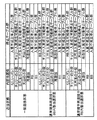
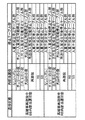
次に、図5〜図7を参照して、遊技状態と、内部当選役と、停止テーブル群選択処理(後述の図27に示す)によって選択される停止テーブル群との関係を説明する。
【0049】
前記遊技状態は、内部当選する可能性のある役の種類、再遊技に内部当選する確率及び入賞成立を実現することが可能なボーナスの種別により概ね7種類に区別される。具体的には、図5〜図7に示すように「一般遊技状態」、「通常確率再遊技中BB内部当選状態」、「通常確率再遊技中RB内部当選状態」、「高確率再遊技中BB内部当選状態」、「高確率再遊技中RB内部当選状態」、「BB一般遊技状態」、「RB遊技状態」に区別される。
【0050】
さらに、本実施形態では「チャンスゾーン(後述の図18、図19、図24、図25、図28、図29に示す)」という遊技状態に移行可能としている。この「チャンスゾーン」で、BBの入賞が成立したときは、副制御回路72の制御でBB遊技中にリールの停止順序(停止ボタンの押順)が液晶表示画面5aに表示(報知)されるという特典が与えられる。この特典が与えられるBBを以下「スーパーBB」という。したがって、スーパーBBでは、前述した30回の一般遊技中にBBよりも高い確率で15枚役が入賞成立することとなる。また、「チャンスゾーン」は、図5〜図7に示す7種類の遊技状態とは独立に発生、期間延長及び終了するものである。
【0051】
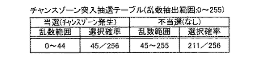
具体的には、「チャンスゾーン」の発生条件は、BBが終了すること、又は所定の小役(ここでは、チェリー)に内部当選し、図8に示すチャンスゾーン突入抽選テーブルに基づいたチャンスゾーン突入抽選に当選すること(後述する図23のST1504の“YES”)である。また、「チャンスゾーン」の終了条件は、予め設定されたゲーム数(規定ゲーム数)が消化されること、又は後述の高確率再遊技終了抽選処理(図23に示す)で用いられるストック解除抽選テーブル(後述の図9に示す)に基づいて、ストック解除抽選に当選することである。さらに、「チャンスゾーン」の期間延長条件は、「チャンスゾーン」にあってチェリーに内部当選し、前記チャンスゾーン突入テーブルに基づいたチャンスゾーン突入抽選に当選することであり、期間延長条件が満たされた場合には、所定のチャンスゾーンゲーム数分(ここでは、50ゲーム)、期間延長するようにしている。なお、スーパーBB入賞成立、チェリーの内部当選によるチャンスゾーン突入当選によって設定されたチャンスゾーンゲーム数の減算(消化)は、ゲーム毎に行われる。
【0052】
また、「チャンスゾーン」を除く各遊技状態間の移行は、後述の遊技状態監視処理(図20に示す)及び高確率再遊技フラグのオン、オフの切り換えにより行われる。なお、各遊技状態には、ボーナスに内部当選したゲームにおいてボーナスの入賞が不成立となるようなリール3L、3C、3Rの停止制御が行われるという共通点がある。
【0053】
また、本実施形態では、ボーナスに内部当選した後、ボーナスの入賞が成立するまでの間、ボーナスを内部当選役として保持する(一般に、「持ち越し」又は「ストック」と称される)。さらに、ボーナスに内部当選した状態(ストック状態)においても、ボーナスに内部当選するようになっている。そして、入賞が成立することなく複数回ボーナスに内部当選した場合には、その回数を前述のストック数カウンタによって計数(貯留)し、その回数分のボーナスの入賞成立を実現可能にしている。ボーナス(BB、RBを含む)の入賞成立を実現可能な回数を、以下「ストック数」という。なお、BBストック数、RBストック数は前述したようにRAM33に記憶されている。
【0054】
ここで、BBの入賞成立を契機として発生し、「BB一般遊技状態」及び「RB遊技状態」により構成される遊技状態を総称して、以下「BB遊技状態」という。また、「通常確率再遊技中BB内部当選状態」、「通常確率再遊技中RB内部当選状態」、「高確率再遊技中BB内部当選状態」及び「高確率再遊技中RB内部当選状態」は、ボーナスに内部当選している状態であり、これらを総称して、以下「内部当選状態」という。なお、「内部当選状態」には、ボーナスを待ち越してボーナスフラグが“オン”となっている状態(ヒットリクエストフラグが“20(H)”又は“10(H)”である状態)を含む。また、「高確率再遊技中BB内部当選状態」及び「高確率再遊技中RB内部当選状態」は、再遊技に内部当選する確率が高い状態(高確率再遊技フラグがセットされた状態)であり、これらを総称して、以下「高確率再遊技中(高確率再遊技期間)」という。また、「一般遊技状態」、「通常確率再遊技中BB内部当選状態」及び「通常確率再遊技中RB内部当選状態」は、再遊技に内部当選する確率が通常の状態(高確率再遊技フラグがセットされていない状態)であり、これらを総称して、以下「通常確率再遊技中」という。
【0055】
「高確率再遊技中」の発生条件は、ヒットリクエストフラグが“00(H)”であるときにボーナスに内部当選したこと(後述する図22のST1409の判別が“NO”)、又はBB遊技状態又はRB遊技状態の終了時においてボーナスストック数が“0”でないこと(後述する図22のST1412を行うこと)である。また、「高確率再遊技中」の終了条件は、「なし(ハズレ)」に内部当選すること、又は高確率再遊技中の終了抽選(ストック解除抽選)に当選すること(後述する図23のST1504の判別が“YES”)である。ここで、「高確率再遊技中」は「不許可遊技状態」に含まれる。
【0056】
ここで、「ヒットリクエストフラグ」は、あるゲームの状況(ボーナスを持ち越しているか否か、持ち越しているボーナスの種類など)を示すものであり、その次のゲームにおいて遊技状態の移行の契機となり得るフラグ(情報)である。具体的には、あるゲームにおいて「ヒットリクエストフラグ」が“20(H)”であるとき、その次のゲームにおける遊技状態は、「通常確率再遊技中BB内部当選状態」又は「高確率再遊技中BB内部当選状態」である。また、あるゲームにおいて「ヒットリクエストフラグ」が“10(H)”であるとき、その次のゲームにおける遊技状態は、「通常確率再遊技中RB内部当選状態」又は「高確率再遊技中RB内部当選状態」である。また、あるゲームにおいて「ヒットリクエストフラグ」が“00(H)”であるとき、その次のゲームにおける遊技状態は、「一般遊技状態」である。なお、「ヒットリクエストフラグ」は、後述の図22のST1410でセットされ、ST1409の判別において用いられる。
【0057】
「高確率再遊技フラグ」は、「高確率再遊技中」であるか否かを判別するためのフラグである。具体的には、「高確率再遊技フラグ」は、「高確率再遊技中」においては、“オン”の状態にある。また、「通常確率再遊技中」においては、基本的に“オフ”の状態にある。この「高確率再遊技フラグ」は、後述の図22のST1412で“オン”とされ、後述の図23のST1506で“オフ”とされる。なお、フラグが“オン”の状態とは、RAM33の所定領域に“1”を示す情報が記憶されていることをいう。また、フラグが“オフ”の状態とは、RAM33の所定領域に“0”を示す情報が記憶されていることをいう。
【0058】
次に、図5〜図7の停止テーブル群の欄に示すテーブル群についてさらに説明する。
【0059】
ここで、選択される停止テーブル群の内容は、基本的に、遊技状態及び内部当選役毎に変化し得るものであるが、本実施形態では、前記停止テーブル群の名称を、入賞の可能性の有無及びその可能性がある役の種類に基づいて定めている。このため、本実施形態では、同一の名称の停止テーブル群が選択されたとしても、常にリール3L、3C、3Rの停止態様までもが一致するわけではない。「入賞不成立停止テーブル群」が選択された場合には、内部当選役、遊技状態に拘らず、いずれの役の入賞も成立することはない。「入賞成立可能停止テーブル群」が選択された場合には、対応する役の入賞成立は可能であるが、その他の役の入賞成立を実現することは基本的にできない。例えば、「三尺玉入賞成立可能停止テーブル群」が選択された場合には、「三尺玉の小役」の入賞成立を実現し得るが、BBなどの他の役の入賞成立を実現することはできない。また、「再遊技入賞成立可能停止テーブル群」が選択された場合には、「再遊技」の入賞成立を実現し得るが、他の役の入賞成立を実現することはできない。
【0060】
「一般遊技状態」では、ボーナスに内部当選した場合には、「入賞不成立停止テーブル群」が選択される。このため、ボーナスの入賞成立を実現することはできない。
【0061】
「通常確率再遊技中BB内部当選状態」では、後述する確率抽選処理(図21、図22に示す)で用いられる通常確率再遊技中用確率抽選テーブル(図10(1)に示す)に基づいてボーナスに内部当選した場合には、「入賞不成立停止テーブル群」が選択され、ボーナスの入賞成立を実現することはできない。他方、前記通常確率再遊技中用確率抽選テーブルに基づき、“12307/16384”の確率で「なし(ハズレ)」に内部当選した場合には。「BB入賞成立可能停止テーブル群」が選択されるので、BBの入賞成立を実現することができる。
【0062】
「通常確率再遊技中RB内部当選状態」では、図10(1)の通常確率再遊技中用確率抽選テーブルに基づいてボーナスに内部当選した場合には、「入賞不成立停止テーブル群」が選択され、ボーナスの入賞成立を実現することはできない。他方、前記通常確率再遊技中用確率抽選テーブルに基づき、“12307/16384”の確率で「なし(ハズレ)」に内部当選した場合には、「RB入賞成立可能停止テーブル群」が選択されるので、RBの入賞成立を実現することができる。
【0063】
「高確率再遊技中BB内部当選状態」では、後述する確率抽選処理(図21、図22に示す)で用いられる高確率再遊技中確率抽選テーブル(図10(2)に示す)に基づいてボーナスに内部当選した場合には、「入賞不成立停止テーブル群」が選択され、ボーナスの入賞成立を実現することはできない。但し、前記高確率再遊技中確率抽選テーブルに基づいて「なし(ハズレ)」に内部当選した場合(いずれの役にも内部当選しない場合)には、BBの入賞成立が許可される(高確率再遊技フラグが“オフ”となる)。なお、前記高確率再遊技中確率抽選テーブルでは、「なし(ハズレ)」に内部当選する確率は“1/16384”であり、稀である。また、前記高確率再遊技中確率抽選テーブルに基づいて、「再遊技」に内部当選した場合には、後述の停止テーブル群選択処理(図27に示す)で用いられる再遊技用選択テーブル(図11に示す)に基づいて「再遊技入賞成立可能停止テーブル群」又は「入賞不成立停止テーブル群」が選択される。
【0064】
「高確率再遊技中RB内部当選状態」では、図10(2)の高確率再遊技中確率抽選テーブルに基づいてボーナスに内部当選した場合には、「入賞不成立停止テーブル群」が選択され、ボーナスの入賞成立を実現することはできない。但し、前記高確率再遊技中確率抽選テーブルに基づき、“1/16384”の確率で「なし(ハズレ)」に内部当選した場合には、RBの入賞成立が許可される(高確率再遊技フラグが“オフ”となる)。また、前記高確率再遊技中確率抽選テーブルに基づいて「再遊技」に内部当選した場合には、図11の再遊技用選択テーブルに基づいて「再遊技入賞成立可能停止テーブル群」又は「入賞不成立停止テーブル群」が選択される。
【0065】
なお、図10(2)の高確率再遊技中用確率抽選テーブルによれば、「高確率再遊技中」において「再遊技」に内部当選する確率は、“14551/16384”である。従って、「高確率再遊技中」において再遊技の入賞が成立する確率は、「再遊技入賞成立可能停止テーブル群」が選択される確率を考慮すると、約“0。1370(“14551/16384”ד10111/65536”)”である。他方、「通常確率再遊技中」では、必ず「再遊技入賞成立可能停止テーブル群」が選択されるので、「再遊技」に内部当選する確率は、その入賞が成立する確率と等しい。すなわち、「通常確率再遊技中」において再遊技の入賞が成立する確率は、約“0。1370(“2245/16384”)”である。このように、本実施形態では、「高確率再遊技中」及び「通常確率再遊技中」において「再遊技」の入賞が成立する確率が等しくなっている。
【0066】
「BB一般遊技状態」及び「RB遊技状態」では、「なし(ハズレ)」に内部当選した場合に、「入賞不成立停止テーブル群」が選択され、ハズレの入賞成立を実現することはできない。
【0067】
次に、図12〜図14を参照して、前述した停止テーブル群を構成する「停止テーブル」について説明する。これは、滑りコマ数決定処理(後述の図16のST21)で使用されるものである。
【0068】
「停止テーブル」には、各リール3L、3C、3Rの「停止操作位置」、「停止制御位置」、及び「滑りコマ数」が示されている。「停止操作位置」は、各リール3L、3C、3Rに対応して設けられた停止ボタン7L、7C、7Rが操作されたとき、センターライン8cに位置していた図柄(具体的には、図柄の中心がセンターライン8cの上方に位置し、その中心がセンターライン8cの位置に最も近い図柄)のコードナンバーを表わす。「停止制御位置」とは、停止操作が行われたリールが停止したとき、センターライン8cの位置に停止表示される図柄のコードナンバーを表わす。「滑りコマ数」は、停止ボタンが操作された後、リールが停止するまでの間に表示窓内を移動した図柄の数を示す(リールが停止するまでの間における図柄の移動量(移動距離)を示す)。また、「滑りコマ数」は、停止ボタンが操作されたとき、所定の入賞ラインに位置していた図柄のコードナンバーと、実際にリールが停止したときに、その入賞ラインに停止した図柄のコードナンバーとの差の絶対値により表わされる。この「滑りコマ数」は、「引き込み数」と称されることもある。
【0069】
ここで、本実施形態では、いわゆる「滑りコマ数」を最大“4コマ”としている。例えば、右のリール3Rの回転中において、コードナンバー“10”の“HANABI(図2の図柄93)”がセンターライン8cの位置に到達したとき、停止ボタン7Rが操作された場合、コードナンバー“14”の“ドンちゃん(図2の図柄91)”をセンターライン8cの位置に停止表示するように右のリール3Rを停止制御することができる。
【0070】
第1〜第3の停止テーブルは、それぞれ、左のリール用(a)、中央のリール用(b)、及び右のリール用(c)の“三つ”のテーブルにより構成されている。また、各停止テーブルには、予めテーブル番号(ここでは、第1〜第3に相当する)が定められている。なお、一つのゲームでは、必ずしも一つの停止テーブルが“三つ”のリール3L、3C、3Rの停止制御に用いられるものではない。例えば、一つのゲームが開始して“三つ”のリール3L、3C、3Rが回転しているときに行うリールの停止操作(以下「第1停止操作」という)に対応する停止制御に用いる停止テーブルと、一つのゲームが開始して“三つ”のリール3L、3C、3Rが回転を開始した後、“一つ”のリールのみが回転しているときに行うリールの停止操作(以下「第3停止操作」という)に対応する停止制御に用いる停止テーブルのテーブル番号が異なる場合がある。また、一つのゲームが開始して“三つ”のリール3L、3C、3Rが回転を開始した後、“二つ”のリールが回転しているときに行うリールの停止操作を、以下「第2停止操作」という。
【0071】
また、複数の停止テーブル群に一つの停止テーブルが属する場合がある。例えば、一つの停止テーブルが「チェリー入賞成立可能停止テーブル群」及び「入賞不成立停止テーブル群」のいずれにも属する場合がある。また、例えば「再遊技入賞成立可能停止テーブル群」が選択された場合などには、「第1停止操作」の「停止操作位置」、乱数抽選の結果などに基づいて入賞成立を示す図柄組合せ(“扇子‐扇子‐扇子”など)が並ぶ有効ラインを決定するようにしている。また、「第3停止操作」に対応するリールの停止制御では。内部当選していない役(持ち越されていない役を含む)の入賞が成立すること(以下「誤入賞」という)を防止する措置をとるようにしている。
【0072】
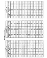
図12及び図13は、「入賞不成立停止テーブル群」などに含まれる第1の停止テーブル及び第2の停止テーブルを示す。図12では、右のリール用のテーブルにおける「滑りコマ数」が全て“4コマ”となっている。また、図13では、中央のリール用のテーブルにおける「滑りコマ数」が全て“4コマ”となっている。
【0073】
図14は、再遊技入賞成立可能停止テーブル群などに含まれる第3の停止テーブルを示す。この停止テーブルは、例えば「停止操作位置」がコードナンバー“01”、“10”及び“16”とは異なる場合であり、“扇子‐扇子‐扇子”が並ぶ有効ラインとしてセンターライン8cが選択された場合に使用される。
【0074】
図14において、左のリール3Lの「停止操作位置」のコードナンバー“01”、“10”及び“16”の場合を除き、「停止制御位置」は、コードナンバー“00”、“06”、“09”又は“15”のいずれかである。図2に示す図柄列において、これらに対応する図柄は“扇子”である。
【0075】
図14において、中央のリール3Cの「停止制御位置」は、コードナンバー“03”、“07”、“11”、“15”又は“20”のいずれかである。図2に示す図柄列において、これらに対応する図柄は“扇子”である。
【0076】
図14において、右のリール3Rの「停止制御位置」は、コードナンバー“02”、“07”、“11”、“15”又は“19”のいずれかである。図2に示す図柄列において、これらに対応する図柄は“扇子”である。
【0077】
したがって、図14に示す第3の停止テーブルが各リール3L、3C、3Rの停止制御に使用された場合には、「再遊技入賞成立可能停止テーブル群」となり、センターライン8cに沿って“扇子‐扇子‐扇子”が並び、再遊技の入賞成立が実現可能となる。
【0078】
次に、図15を参照して、「滑りコマ数」の検索順序について説明する。前述したように「滑りコマ数」に従って「第3停止操作」に対応するリールを停止制御しても、遊技状態と内部当選役とに応じて選択された停止テーブル群では成立を許可しない役が入賞するおそれがあり、このような入賞を「誤入賞」という。そこで、停止制御に先立ってそれぞれの「滑りコマ数」について「誤入賞」が成立するか否かを検索(判別)するが、このときの「滑りコマ数」の順序(順番)を検索順序という。この検索順序は、「停止テーブル」及び「停止操作位置」から決定される「滑りコマ数」に基づいて停止制御することにより「誤入賞」が成立する場合、「誤入賞」が成立しないことを条件に「滑りコマ数」として決定される“0”〜“4”の「滑りコマ数」の優先順位を示すものである。
【0079】
具体的には、「停止テーブル」及び「停止操作位置」から決定される「滑りコマ数」が“0”の場合に「誤入賞」が成立するとき、次いで「滑りコマ数」が“1”の場合に「誤入賞」が成立するか否かを判別する。この判別で「誤入賞」が成立しないときは、「滑りコマ数」が“1”と決定される。また、「誤入賞」が成立するときは、次いで「滑りコマ数」が“2”の場合に「誤入賞」が成立するか否かを判別する。この判別で「誤入賞」が成立しないときは、「滑りコマ数」が“2”と決定される。また、「誤入賞」が成立するときは、次いで「滑りコマ数」が“3”の場合に「誤入賞」が成立するか否かを判別する。この判別で「誤入賞」が成立しないときは、「滑りコマ数」が“3”と決定される。また、「誤入賞」が成立するときは、次いで「滑りコマ数」が“4”の場合に「誤入賞」が成立するか否かを判別する。この判別で「誤入賞」が成立しないときは、「滑りコマ数」が“4”と決定される。「停止テーブル」及び「停止操作位置」から決定される「滑りコマ数」が“1”、“2”、“3”、“4”の場合の検索順序は図15の矢印で示すとおりである。ここでは、“0”〜“4”のいずれか一つの「滑りコマ数」で「誤入賞」が成立しないように停止テーブル(第1〜第3の停止テーブルを含む)を構成し、適宜選択するようにしている。なお、「滑りコマ数」の検索順序は、図15に示すものに限らず、例えば「4→3→2→1→0」「4→0→3→1→2」など、任意の順序とすることができる。
【0080】
次に、図16〜図18に示すフローチャートを参照し、主制御回路71のCPU31の処理について説明する。
【0081】
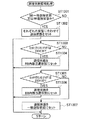
初めに、CPU31は、遊技開始時の初期化を行う(ステップ(以下、STと表記する)1)。具体的には、RAM33の記憶内容の初期化、通信データの初期化などを行う。次いで、ゲーム終了時のRAM33の所定の記憶内容を消去する(ST2)。具体的には、前回のゲームに使用されたRAM33の書き込み可能エリアのデータの消去、RAM3の書き込みエリアヘの次のゲームに必要なパラメータの書き込み、次のゲームのシーケンスプログラムの開始アドレスの指定などを行う。次いで、前回のゲーム終了後、すなわち全リール3L、3C、3R停止後から“30秒”経過したか否かを判別する(ST3)。この判別が“YES”であれば、副制御回路72に対し、「待機画面(デモ画像)」の表示を要求するために「待機画面コマンド」を送信する(ST4)。
【0082】
次いで、CPU31は、メダルの自動投入の要求があるか、すなわち前回のゲームで再遊技の入賞が成立したか否かを判別する(ST5)。この判別が“YES”のときは、投入要求分のメダルを自動投入し(ST6)、ST8に移る。ST5の判別が“NO”のときは、メダル投入口22へのメダル投入又はBETスイッチ11、12、13の操作を受け付ける(ST7)。
【0083】
次いで、CPU31は、スタートレバー6の操作に基づくスタートスイッチ6Sからの入力があるか否かを判別する(ST8)。この判別が“YES”のときは前回のゲームが開始してから“4.1秒”経過しているか否かを判別し(ST9)、この判別が“YES”のときはST11に移り、“NO”のときはST10に移る。ST10では、「ゲーム開始待ち時間消化処理」を行う。具体的には、前回のゲームが開始してから“4.1秒”経過するまでの間、遊技者のゲームを開始する操作に基づく入力を無効にする処理を行う。
【0084】
次いで、CPU31は、遊技状態に応じた確率抽選テーブル(図10(1)、図10(2)を含む)をRAM33にセットするのと同時に抽選用の乱数を抽出し(ST11)、1ゲーム監視用タイマをセットする(ST12)。ST11の処理で抽出した乱数は、後で説明する確率抽選処理(図21、図22に示す)において使用される。ST12の処理の1ゲーム監視用タイマには、遊技者の停止ボタンの停止操作によらずに自動的にリールを停止させるための自動停止タイマが含まれる。
【0085】
次いで、CPU31は、後述の遊技状態監視処理(図20に示す)を行う(ST13)。次いで、CPU31は、後述の確率抽選処理(図21、図22に示す)を行う(ST14)。この確率抽選処理(内部抽選処理)は、遊技状態に応じて確率抽選テーブルを使用し、ST11において抽出した乱数値がどの役の乱数範囲に属するかを判別し、内部当選役(成立フラグ)を決定するものである。次いで、CPU31は、後述の高確率再遊技終了関連処理(図23に示す)を行う(ST15)。次いで、CPU31は、後述のチャンスゾーンクリア処理(図24に示す)を行う(ST16)。次いで、CPU31は、後述の停止テーブル群選択処理(図27に示す)を行う(ST17)。
【0086】
次いで、CPU31は、停止ボタンが“オン”であるか否かを判別する(ST18)。具体的には、いずれかの停止ボタンが操作されたか否かを判別する。この判別が“YES”のときは、ST20に移り。“NO”のときは、ST19に移る。ST19では、自動停止タイマの値が“0”であるか否かを判別し、この判別が“YES”のときは、ST20に移り、“NO”のときは、STl8に移る。
【0087】
図17のST20において、CPU31は、後述の滑り関連処理(図28に示す)を行う(ST21)。次いで、CPU31は、滑りコマ数分、停止操作された停止ボタンに対応するリールを回転させてから停止させる(ST21)。次いで、CPU31は、全てのリールが停止したか否かを判別する(ST22)。この判別が“YES”のときは、全てのリールが停止したことを示す「全リール停止コマンド」を送信してST23に移り、“NO”のときは、ST18に移る。
【0088】
図18のST23では、CPU31は入賞検索を行う。入賞検索とは、表示窓4L、4C、4Rの図柄の停止態様に基づいて入賞役(入賞が成立した役)を識別するための入賞フラグをセットすることである。具体的には、センターライン8cに沿って並ぶ図柄のコードナンバー及び入賞判定テーブルに基づいて入賞役を識別する。
【0089】
次いで、CPU31は、入賞フラグが正常であるか否かを判別する(ST24)。この判別が”NO”のときはイリーガルエラーの表示を行う(ST25)。この場合、遊技は中止となる。ST24の判別が”YES”の場合、CPU31は、遊技状態に応じてメダルのクレジット、又は払出しを行わせる(ST26)。
【0090】
次いで、CPU31は、「ロック時間処理」を行う(ST27)。この「ロック時間処理」では、全リールが停止した後、「演出時間」が経過するまでの間、次のゲームを開始するための操作を無効とする。具体的には、スタートレバー6の操作を無効とする。
【0091】
次いで、CPU31は、「WINランプ点灯処理」を行う(ST28)。この「WINランプ点灯処理」においては、所定の条件下でWINランプ17を点灯させる処理を行う。
【0092】
次いで、CPU31は、遊技状態がBB遊技状態又はRB遊技状態であるか否かを判別する(ST29)。この判別が”NO”のときは、後述のBB・RB入賞チェック処理(図29に示す)を行う(ST30)。また、前記判別が”YES”のときは、BB又はRBの「遊技数チェック処理」を行う(ST31)。この「遊技数チェック処理」では、RB遊技状態が発生した回数、BB中一般遊技状態のゲーム数、RB遊技状態における入賞回数、及びRB遊技状態におけるゲーム数をチェックする。
【0093】
次いで、CPU31は、ST31の処理結果からBB終了遊技状態が終了か否かを判別する(ST32)。この判別が”YES”のときは、BB遊技状態を終了してRAM33の所定の記憶内容を消去する(ST33)。
【0094】
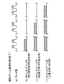
次いで、CPU31は、前述した「チャンスゾーン」を規定ゲーム数(ここでは、100ゲーム)だけ、発生させる(ST34)。例えば、図19に示すタイミングでチャンスゾーンが発生する。ここでは、5ゲーム目(プレイ数(5))をもってBBが終了し、6ゲーム目(プレイ数(6))からチャンスゾーンが発生している。
【0095】
次に、図20を参照し、遊技状態監視処理(図17のST13)についてさらに説明する。ここで、以下の処理に用いるヒットリクエストフラグは、一般遊技状態においてBB又はRBに内部当選したとき、及びBB遊技状態などが終了したときに変更される可能性がある。
【0096】
初めに、CPU31は、遊技状態がBB一般遊技状態又はRB遊技状態であるか否かを判別する(ST1301)。この判別が“YES”のときは、それぞれの遊技状態に合わせて遊技状態をセットする(ST1302)。具体的には、ST31(図18に示す)の処理で移行した遊技状態をセットする。ST1301の判別が“NO”のときは、ヒットリクエストフラグが“10(H)”であるか否かを判別する(ST1303)。この判別が“YES”のときは、遊技状態をRB内部当選状態にセットする(ST1304)。具体的には、高確率再遊技フラグが“オン”の場合には、遊技状態を「高確率再遊技中RB内部当選状態」にセットし、“オフ”の場合には、「通常確率再遊技中RB内部当選状態」にセットする。
【0097】
また、ST1303の判別が“NO”のときは、ヒットリクエストフラグが“20(H)”であるか否かを判別する(ST1305)。この判別が“YES”のときは、遊技状態をBB内部当選状態にセットする(ST1306)。具体的には、高確率再遊技フラグが“オン”の場合には、遊技状態を「高確率再遊技中BB内部当選状態」にセットし、“オフ”の場合には、「通常確率再遊技中BB内部当選状態にセットする。また、ST1305の判別が“NO”のときは、遊技状態を一般遊技状態にセットする(ST1307)。
【0098】
このように、ゲーム開始時におけるヒットリクエストフラグ及び高確率再遊技フラグに基づいて遊技状態の変更を行うようにしている。つまり、前回のゲームにおける遊技状態に応じて遊技状態を変更するようにしている。例えば、後述の確率抽選処理(図21、図22に示す)でヒットリクエストフラグの内容が変更され、ST1412で高確率再遊技フラグが“オフ”から“オン”に変更されるが、その変更を契機とした遊技状態の変更は、次のゲームの開始時に行われることとなる。そして、この遊技状態監視処理においてセットされた遊技状態に基づいて前記確率抽選処理、後述する停止テーブル群選択処理(図27に示す)、後述する滑り関連処理(図28に示す)などが行われる。
【0099】
次に、図21及び図22を参照し、確率抽選処理(図17のST14)についてさらに説明する。
【0100】
初めに、CPU31は、遊技状態がBB一般遊技状態又はRB遊技状態であるか否かを判別する(ST1401)。この判別が“YES”のときは、ST1405に移り、“NO”のときは、ST1402に移る。ST1402では、高確率再遊技フラグが“オフ”であるか否か、すなわち「通常確率再遊技中」であるか否かを判別する。この判別が“YES”のときは、ST1403に移り、“NO”のときは、ST1404に移る。
【0101】
ST1403では、図10(1)に示す通常確率再遊技中用確率抽選テーブルに基づいて内部当選役の抽選を行い、ST1406に移る。これは、BET数が“3”のとき、一般遊技状態又は内部当選状態において内部当選役を決定する際に使用される。この確率抽選テーブルを用いると、確率抽選処理における乱数の抽出範囲“0”〜“16383”のうち、“136”〜“2380”の範囲内の乱数が抽出された場合に「再遊技」が内部当選役となる。「再遊技」に内部当選する確率は、“2245/16384”である。
【0102】
ST1404では、図10(2)に示す高確率再遊技中用確率抽選テーブルに基づいて内部当選役の抽選を行い、ST1406に移る。この高確率再遊技中用確率抽選テーブルは、BET数が“3”のとき、一般遊技状態又は内部当選状態において内部当選役を決定する際に使用される。この確率抽選テーブルを用いると、確率抽選処理における乱数の抽出範囲“0”〜“16383”のうち、“136”〜“14686”の範囲内の乱数が抽出された場合に「再遊技」が内部当選役となる。「再遊技」に内部当選する確率は、“14551/16384”である。
【0103】
また、ST1401の判別が“YES”のときは、ボーナス中用確率抽選テーブル(図示せず)に基づいて内部当選役の抽選を行い(ST1405)、ST1406に移る。
【0104】
ST1406では、ST1403〜ST1405の抽選処理で得られた内部当選役の情報をRAM33に格納し、図22のST1407に移る。
【0105】
図22のST1407では、内部当選役がBB又はRBであるか否かを判別する。この判別が“YES”のときは、ST1408に移り、“NO”のときは、ST15に移る。ST1408では、前述したストック数カウンタにより、内部当選したボーナスの種別に応じてBBストック数又はRBストック数に“1”を加算し、ST1409に移る。ST1409では、セットされているヒットリクエストフラグが“10(H)”又は“20(H)”であるか否かを判別する。この判別が“NO”のとき、すなわち「一般遊技状態」であるときは、ST1410に移る。ST1409の判別が“YES”のときは、ST15に移る。ST1410では、ボーナスの種別に基づいてヒットリクエストフラグをセットする。具体的には,内部当選役がRBであるときは、ヒットリクエストフラグとして“10(H)”をセットし、BBであるときは、“20(H)”をセットする。次いで、内部当選したボーナスのストック数から“1”減算する(ST1411)。次いで、高確率再遊技フラグを“オン”とし(ST1412)、ST15に移る。
【0106】
次に、図23を参照し、高確率再遊技終了関連処理(図17のST15)についてさらに説明する。
【0107】
初めに、CPU31は、高確率再遊技フラグが“オン”であるか否かを判別する(ST1501)。この判別が“YES”のときは、ボーナスフラグが“オン”であること(ストック状態)を示すので、ST1502に移り、“NO”のときは、ST16に移る。ST1502では、前述の確率抽選処理(図21、22に示す)で「なし(ハズレ)」に内部当選したか否かを判別する。この判別が“YES”のときは、ST1505に移り、“NO”のときは、ST1503に移る。ST1503では、RAM33の所定領域に設定されている現在の滞在モードを参照し、この滞在モードに対応するストック解除抽選テーブルに基づいてストック解除抽選を行う。このストック解除抽選テーブルは、換言すれば、高確率再遊技状態から通常遊技状態へ移行するか否かを抽選するための高確率再遊技終了抽選テーブルである。図9のストック解除抽選テーブルによれば、「高確率再遊技中」において高確率再遊技の終了に当選する確率は、“192/256”である。本実施形態では、あるストック解除時点から次のストック解除時点までの期間ごとに、ストック解除抽選の当選確率を示すモードが切り替わり、ストック解除抽選に使用されるストック解除抽選テーブルもモードごとに切り替わるようにしている。したがって、図9に示したものを含む複数異種のストック解除抽選テーブルを有している。
【0108】
次いで、ST1503のストック解除抽選で当選したか否かを判別する(ST1504)。この判別が“YES”のときは、ST1505に移り、“NO”のときは、ST16に移る。ST1505では、ストック解除対象のボーナスを3:1の割合でBBとRBとに振り分ける。ここでは、「高確率再遊技状態」において、内部当選時にBBストック数とRBストック数とが前記ストック数カウンタで計数(貯留)され、両者の合計がストック数としてRAM33に記憶されている。ストック解除時には、例えば前記ストック数に基づいて、“3/4”の確率でBBが入賞し、“1/4”の確率でRBが入賞するように振り分けるよう、制御している。
【0109】
次いで、CPU31は、高確率再遊技フラグを“オフ”として(ST1506)、「高確率再遊技中」を終了させ、通常遊技状態に移行させる。なお、「高確率再遊技中」が終了することにより、後述の停止テーブル群選択処理(図27のST1705)では、BB入賞成立可能停止テーブル群又はRB入賞成立可能停止テーブル群が選択されることとなる。
【0110】
次に、図24を参照し、チャンスゾーンクリア処理(図17のST16)についてさらに説明する。
【0111】
初めに、CPU31は、高確率再遊技フラグが“オフ”であるか否かを判別する(ST1601)。この判別が“YES”のときは、ST1602に移り、“NO”のときは、ST17に移る。
【0112】
ST1602では、ST1505(図23に示す)で振り分けられた入賞ボーナスがRBであるか否かを判別する。この判別が“NO”のときは、ST1603に移り、“YES”のときは、ST17に移る。ST1603では、ST1504で振り分けられた入賞ボーナスがBBであるか否かを判別する。この判別が“YES”のときは、ST1604に移り、“NO”のときは、ST1606に移る。ST1606では、前述のチャンスゾーンの規定ゲーム数を消化したか否かを判別する。この判別が“YES”のときは、ST1604に移り、“NO”のときは、ST17に移る。
【0113】
次いで、CPU31は、RAM33のチャンスゾーンゲーム数カウンタをリセットする(ST1604)。次いで、CPU31は、RAM33の所定領域に設定されたチャンスゾーン中フラグを“オフ”とする。こうしてチャンスゾーンが終了する。
【0114】
以上のようなチャンスゾーンクリア処理により、図25に示すタイミングでチャンスゾーンが終了する。前述したようにストック解除抽選に当選した場合(図23のST1504の“YES”)にはボーナス入賞成立が可能となるが、ここでは、チャンスゾーン中(h)かつ高確率再遊技中(ストック状態)において、ハズレに内部当選してBBに入賞し、35ゲーム目(プレイ数(35))の立ち上りでストック解除抽選に当選したために、35ゲーム目をもってチャンスゾーンは終了している。また、チャンスゾーン中(i)かつ高確率再遊技中(ストック状態)において75ゲーム目(プレイ数(75))の立ち上りでストック解除抽選に当選したために、75ゲーム目をもってチャンスゾーンは終了している。チャンスゾーン中(j)かつ高確率再遊技中(ストック状態)において、125ゲーム目(プレイ数(125))の立ち上りでストック解除抽選に当選したために、125ゲーム目をもってチャンスゾーンは終了している。また、図26に示すタイミングでチャンスゾーンが終了する。ここでは、滑り発生によるチャンスゾーン突入抽選に当選して50ゲーム上乗せされた場合のチャンスゾーン中(h)において、50ゲーム目(プレイ数(50))でチャンスゾーンを消化終了している。また、BB終了により100ゲームのチャンスゾーンが設定された場合のチャンスゾーン中(i)において、100ゲーム目(プレイ数(100))でチャンスゾーンを消化終了している。また、滑り発生によるチャンスゾーン突入抽選に当選して100ゲームのチャンスゾーンに50ゲームが上乗せされた場合のチャンスゾーン中(j)において、150ゲーム目(プレイ数(150))でチャンスゾーンを消化終了している。
【0115】
次に、図27を参照し、停止テーブル群選択処理(図17のST17)についてさらに説明する。
【0116】
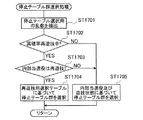
初めに、CPU31は、停止テーブル選択用の乱数を抽出する(ST1701)。抽出された乱数値は、遊技状態及び内部当選役に対応する停止テーブル群に含まれる停止テーブルのうち、いずれの停止テーブルを選択するかを決定するために用いられる。次いで、「高確率再遊技中」であるか否かを判別する(ST1702)。この判別が“YES”のときは、ST1703に移り、“NO”のときは、ST1705に移る。ST1703では、内部当選役が再遊技であるか否かを判別する。この判別が“YES”のときは、ST1704に移り、“NO”のときは、ST1705に移る。
【0117】
ST1704では、“0”〜“65535”の範囲から抽出した乱数値及び再遊技用選択テーブル(図11に示す)に基づいて「再遊技入賞成立可能停止テーブル群」又は「入賞不成立停止テーブル群」のいずれかを選択し、図17のST18に移る。図11の再遊技用選択テーブルを用いると、確率抽選処理における乱数の抽出範囲“0”〜“65535”のうち、“0”〜“10110” の範囲内の乱数が抽出された場合に「再遊技入賞成立可能停止テーブル群」が選択される。すなわち、再遊技入賞成立可能停止テーブル群を選択する確率は、“10111/65536”である。また、“10111”〜“65535”の範囲内の乱数が抽出された場合に「入賞不成立停止テーブル群」が選択される。すなわち、入賞不成立停止テーブル群を選択する確率は、“55425/65536”である。
【0118】
ST1705では、確率抽選処理(図21、図22に示す)による内部当選役及び遊技状態に基づいて停止テーブル群を選択し(図5〜図7参照)、図17のST18に移る。
【0119】
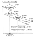
次に、図28を参照し、滑り関連処理(図17のST20)についてさらに説明する。
【0120】
初めに、CPU31は、図17のST17で選択された停止テーブル群、停止操作位置、図柄位置などに応じて滑りコマ数を決定するとき、「滑り」が発生したか否かを判別する(ST2001)。この判別が“YES”のときは、ST2002に移り、“NO”のときは、ST21に移る。なお、前記停止テーブル群は、確率抽選処理(図17のST14)による内部当選役(内部抽選結果に含まれる)及び遊技状態によって選択され、停止操作位置、図柄位置は、停止ボタン7L、7C、7Rの操作及び押順(操作態様に含まれる)によって得られるものである。また、「滑り」とは、停止ボタン7L、7C、7Rの操作による「停止操作位置」及び「停止テーブル」から決定され、かつ前述の「誤入賞」を回避するように決定された「滑りコマ数」が、“0コマ”以外の場合のリールの停止制御の態様を示す。
【0121】
ST2002では、図8に示すチャンスゾーン突入抽選テーブルに基づいてチャンスゾーン突入の抽選を行い、ST2003に移る。前記チャンスゾーン突入抽選テーブルによれば、「滑り発生時」においてチャンスゾーン突入(チャンスゾーン発生、期間延長を含む)に当選する確率は、“45/256”であり、約17%となっている。
【0122】
次いで、前述したチャンスゾーン突入の抽選結果が当選であるか否かを判別する(ST2003)。この判別が“YES”のときは、ST2004に移り、“NO”のときは、ST21に移る。ST2004では、遊技状態がチャンスゾーン中であるか否かを判別する。この判別が“YES”のときは、ST2005に移り、“NO”のときは、ST2006に移り、その後にST21に移る。
【0123】
ST2005では、チャンスゾーンが既に発生しているため、さらにチャンスゾーンの上乗せ処理を行う。具体的には、前述のチャンスゾーンゲーム数カウンタに50ゲームを加算する。ST2006では、チャンスゾーンが発生していないために、RAM33のチャンスゾーンゲーム数カウンタに50ゲームを新たに設定する。
【0124】
以上のようなチャンスゾーン関連処理により、非チャンスゾーンにあっては、停止制御としての「滑り」が発生するタイミングでチャンスゾーンが発生する。また、チャンスゾーンにあっては、停止制御としての「滑り」が発生するタイミングで、この時点の残チャンスゾーンゲーム数に50ゲームが上乗せされて、チャンスゾーンの期間が延長される。
【0125】
次に、図29を参照し、BB・RB入賞チェック処理(図18のST30)についてさらに説明する。
【0126】
初めに、CPU31は、BBの入賞が成立したか否かを判別する(ST3001)。この判別が“YES”のときは、ST3002に移り、“NO”のときは、ST3004に移る。
【0127】
ST3002では、チャンスゾーン中であるか否かを判別する。この判別が“YES”のときは、ST3003に移り、“NO”のときは、ST3004に移る。
【0128】
ST3003では、CPU31は、チャンスゾーン中に入賞が成立したBBをスーパーBBとし、副制御回路72に対してスーパーBB信号を送信する。また、ST3004では、入賞が成立したBBをノーマルBBとして処理する。具体的には、従来のBBと同様にBB中の一般遊技(3枚賭けゲーム)を30回可能とし、この30回の間に再遊技に入賞すると、JACゲーム(1枚賭けゲーム)に移行する。1回のJACゲームは、12回の遊技があり、再遊技がセンターラインに揃うゲームのことであり、その内の8回再遊技を入賞させると終了するものである。このJACゲームが前述のBB中の一般遊技可能な30回の内、3回繰り返されると、BBが終了する。なお、本実施形態では、ボーナスの入賞が成立したとき、主制御回路71から副制御回路72に対し、スーパーBB、ノーマルBB、RBのいずれかを示す信号(コマンド)を送信している。
【0129】
次に、図30を参照し、副制御回路72のスーパーBB信号受信処理について説明する。
【0130】
図30(a)に示すように、副制御回路72を構成するマイクロコンピュータのCPU(図示せず)は、初めに、主制御回路71からのスーパーBB信号を受信したか否かを判別する(ST41)。この判別が“YES”のときは、ST42に移り、“NO”のときは、処理を行わない。ST42では、BB中一般遊技(3枚賭け)を30回行う間に、ノーマルBBよりも高い確率で15枚役が成立するよう、押順報知処理を行う。具体的には、図30(b)に示すように、所定役に内部当選したか否かを判別し(ST421)、この判別が“YES”のときは、内部当選役を入賞成立させるよう、液晶表示画面5aに停止ボタンの押順(すなわち、リールの停止順序)を表示させる(ST422)。
【0131】
なお、チャンスゾーン中に、「高確率再遊技状態」で「ハズレ」に内部当選するか又はストック解除抽選に当選し、かつストックされていたボーナスがBBに振り分けられた場合には、このBBはスーパーBBとなり、副制御回路72により前記スーパーBB信号受信処理が実行される。
【0132】
以上のように、本発明の実施の一形態に係るパチスロ機1(遊技機に含まれる)は、遊技のための操作を行うスタートレバー6及び停止ボタン7L、7C、7R(操作手段に含まれる)と、これらの操作により、遊技に用いる複数の図柄列を変動表示するリール3L、3C、3R(変動表示手段に含まれる)と、スタートレバー6の操作により、乱数を用いて入賞態様を決定するための内部抽選を行う主制御回路71の一部(内部抽選手段に含まれる)と、停止ボタン7L、7C、7Rの押し順(操作態様に含まれる)、主制御回路71の内部抽選結果及び遊技状態により、リール3L、3C、3Rを停止制御する主制御回路71の一部(停止制御手段に含まれる)と、BB(「第1の入賞態様」に含まれる)が成立可能な回数の情報、及びRB(「第2の入賞態様」に含まれる)が成立可能な回数の情報(ストック情報)を記憶する主制御回路71の一部(回数情報記憶手段に含まれる)と、主制御回路71に記憶された回数が1以上であり、かつストック解除抽選に当選するという条件(所定の条件に含まれる)を満足した場合(図23のST1504の“YES”)にBB入賞を成立させる主制御回路71の一部(入賞成立手段に含まれる)とを備えた遊技機であって、チャンスゾーン突入抽選に当選するか(図28のST2004の“NO”)又はBBが終了する(図18のST32の“YES”)という条件(第1の条件に含まれる)を満足した場合に、チャンスゾーン(所定の遊技状態に含まれる)に移行するよう制御する主制御回路71の一部(遊技状態移行手段、移行抽選手段に含まれる)と、前記チャンスゾーンにあり、かつチャンスゾーン突入抽選に当選する(図28のST2004の“YES”)という条件(第2の条件に含まれる)を満足した場合に、前記チャンスゾーンにある期間を延長する主制御回路71の一部(期間延長手段に含まれる)と、前記チャンスゾーンにあって、主制御回路71の一部がBB(スーパーBB)を成立させた場合に、スーパーBBの遊技中、リール3L、3C、3Rの停止態様が入賞成立を示すように、停止ボタン7L、7C、7Rの押順を報知する液晶表示装置5及び副制御回路72(報知手段に含まれる)とを備え、チャンスゾーンの発生条件(第1の条件に含まれる)及びチャンスゾーンの上乗せ条件(第2の条件に含まれる)には、主制御回路71の一部が「滑り」による停止制御(所定の態様に含まれる)を行うこと(例えば、図28のST2001の“YES”)が含まれているので、遊技者にとって有利なチャンスゾーン期間において、さらにリールの「滑り」の発生を契機としたチャンスゾーン突入抽選に当選することによりチャンスゾーンを期間延長できる。よって、遊技者の遊技に対する興味を持続させることができる。
【0133】
また、本実施形態によれば、チャンスゾーンの発生契機はBBが終了したとき、及び「滑り」発生時のチャンスゾーン突入抽選に当選したときの2回あり、BBが終了したときは100%の割合、「滑り」が発生したときは約17%の割合でチャンスゾーンとなるために、遊技者はスーパーBBに当選することを期待しながら遊技できる。
【0134】
また、本実施形態によれば、チャンスゾーンでBB入賞が成立したとき(ストック解除抽選に当選したとき)に、そのチャンスゾーンは終了するが、そのBBの遊技が終了したとき、新たなチャンスゾーンが100ゲーム発生するために、遊技者にとって有利なチャンスゾーンへの機会が持てる。また、非チャンスゾーンにあって、「滑り」の発生を契機としたチャンスゾーン突入抽選に当選したとき、新たなチャンスゾーンが50ゲーム発生するので、BB終了時に発生する100ゲームに比べて少ないものの、遊技者にとって有利なチャンスゾーンの機会がさら増し、遊技者の期待が高まる。さらに、チャンスゾーンにあって、リールの「滑り」の発生を契機としたチャンスゾーン突入抽選に当選したとき、残チャンスゾーンゲーム数に50ゲーム加算される。この加算ゲーム数は、BB終了によるチャンスゾーン発生時の100ゲームよりは少ないものの、遊技者にとって有利なチャンスゾーンが期間延長されるので、遊技者はスーパーBBに当選することを期待しながら遊技できる。
【0135】
さらに、本実施形態によれば、リールの「滑り」の発生を契機とし、所定の確率でチャンスゾーン発生の機会が得られるために、遊技者は、チャンスゾーン発生の機会が得られたことを察知して、遊技に対する興味を持続することとなる。また、遊技者は、チャンスゾーン発生の機会を確かめるため、積極的に「目押し」を行うことになるので遊技者自身の技術の向上につながる。一方、遊技機を提供する側は、チャンスゾーン突入抽選の当選確率を調整してスーパーBBとなる機会を増減できることとなる。
【0136】
また、前述した実施形態ではいわゆるストック機を用いた場合について説明したが、本発明はこのほかに、例えば請求項1に係る発明を非ストック機に適用しても同様の効果が得られるものである。
【0137】
また、前述した実施形態ではスーパーBB遊技中の停止順序(停止ボタンの押順)を報知する方法として液晶画面5aに押順を表示した場合について説明したが、本発明はこれに限られるものではない。このほかに、例えば音声及び画像(アニメーションを含む)によって誘導(ナビゲーション)しても同様の効果が得られるものである。
【0138】
また、前述した実施形態では遊技機としてパチスロ機を用いた場合について説明したが、本発明はこのほかに、パチンコ遊技機などの他の遊技機に適用しても同様の効果が得られるものである。さらに、前述したパチスロ機の動作を家庭用ゲーム機用として凝似的に実行するようなゲームプログラムにおいても、本発明を適用してゲームを実行することができる。その場合、図16〜図18、図20〜図24、図27〜図30に示した処理を実行するためのゲームプログラム、及び図8〜図14に示すテーブルなどの必要データを記録する記録媒体として、CD‐ROM、FD(フレキシブルディスク)、その他任意の記録媒体を利用できる。
【0139】
【発明の効果】
以上説明したように、本発明によれば、遊技者にとって有利な所定の遊技状態(チャンスゾーンを含む)において、第2の条件(リールの滑り発生を契機としたチャンスゾーン突入当選を含む)を満足することによって前記所定の遊技状態の期間を延長するので、遊技者は、有利な遊技状態が延長される機会を得ることにより、遊技に対する興味を持続させることができる。
【図面の簡単な説明】
【図1】本発明の実施の一形態に係るパチスロ機の外観を示す斜視図である。
【図2】図1のパチスロ機のリール上に配列された図柄を示す図である。
【図3】図1のパチスロ機の回路構成を示すブロック図である。
【図4】図1のパチスロ機における役と図柄組合せと払出枚数との関係を示す図である。
【図5】図1のパチスロ機の遊技状態と内部当選役と停止テーブル群との関係を示す図の一部である。
【図6】図1のパチスロ機の遊技状態と内部当選役と停止テーブル群との関係を示す図の一部である。
【図7】図1のパチスロ機の遊技状態と内部当選役と停止テーブル群との関係を示す図の一部である。
【図8】図1のパチスロ機におけるチャンスゾーン突入抽選テーブルを示す図である。
【図9】図1のパチスロ機におけるストック解除抽選テーブルを示す図である。
【図10】図1のパチスロ機における確率抽選テーブルを示す図である。
【図11】図1のパチスロ機における再遊技用選択テーブルを示す図である。
【図12】図1のパチスロ機における第1の停止テーブルを示す図である。
【図13】図1のパチスロ機における第2の停止テーブルを示す図である。
【図14】図1のパチスロ機における第3の停止テーブルを示す図である。
【図15】図1のパチスロ機における滑りコマ数の検索順序を示す図である。
【図16】図1のパチスロ機の主制御回路による処理を表すメインフローチャートである。
【図17】図16に続くメインフローチャートである。
【図18】図17に続くメインフローチャートである。
【図19】図1のパチスロ機におけるチャンスゾーン発生(BB終了時)に関するタイミングチャートである。
【図20】図17の遊技状態監視処理を表すフローチャートである。
【図21】図17の確率抽選処理を表すフローチャートである。
【図22】図21に続くフローチャートである。
【図23】図17の高確率再遊技終了抽選処理を表すフローチャートである。
【図24】図17のチャンスゾーンクリア処理を表すフローチャートである。
【図25】図1のパチスロ機におけるチャンスゾーン終了(ストック解除当選時)に関するタイミングチャートである。
【図26】図1のパチスロ機におけるチャンスゾーン終了(規定ゲーム数消化時)に関するタイミングチャートである。
【図27】図17の停止テーブル群選択処理を表すフローチャートである。
【図28】図17の滑り関連処理を表すフローチャートである。
【図29】図18のBB・RB入賞チェック処理を表すフローチャートである。
【図30】図1のパチスロ機の副制御回路による処理(スーパーBB信号受信処理)を表すフローチャートである。
【符号の説明】
1…遊技機、2…キャビネット、2a…パネル表示部、3L,3C,3R…リール、4L、4C、4R…表示窓、5…液晶表示装置、5a…液晶表示画面、6…スタートレバー、7L,7C,7R…停止ボタン、8a…クロスダウンライン、8b…トップライン、8c…センターライン、8d…ボトムライン、8e…クロスアップライン、9a…1‐BETランプ、9b…2‐BETランプ、9c…最大BETランプ、10…台座部、11…1‐BETスイッチ、12…2‐BETスイッチ、13…最大BETスイッチ、14…C/Pスイッチ、15…メダル払出口、16…メダル受け部、17…当り表示ランプ、18…払出表示部、19…クレジット表示部、20…ボーナス遊技情報表示部、21L,21C,21R…スピーカ、22…メダル投入口、22S…投入メダルセンサ、23…配当表示パネル、30…マイクロコンピュータ、31…CPU、32…ROM、33…RAM、34…クロックパルス発生回路、35…分周器、36…乱数発生器、37…サンプリング回路、38…I/Oポート、39…モータ駆動回路、40…ホッパー、41…ホッパー駆動回路、45…ランプ駆動回路、46…リール停止信号回路、48…表示部駆動回路、49L,49C,49R…ステッピングモータ、50…リール位置検出回路、51…払出完了信号回路、71…主制御回路、72…副制御回路。[0001]
TECHNICAL FIELD OF THE INVENTION
The present invention relates to a gaming machine including a slot machine, a pachislot machine, and a pachinko machine, which controls the fluctuation of a symbol row used in a game by a microcomputer or the like.
[0002]
[Prior art]
2. Description of the Related Art A conventional pachislot machine (included in a gaming machine) displays a mechanical variation display device in which a plurality of rotating reels for variably displaying a symbol row are arranged in a display window, or a symbol on a rotating reel is displayed on a screen. An electric fluctuation display device is provided. This is because, by operating a start lever, a microcomputer or the like drives and controls a variable display device to rotate each rotating reel, so that a symbol row is displayed in a variable manner, and after a predetermined time, it is automatically stopped or a stop button is pressed. Each rotating reel is sequentially stopped by an operation. At this time, when the symbols of the rotating reels appearing in the display window have a specific combination (winning symbol), game media such as medals or coins are paid out.
[0003]
In the current mainstream models, a predetermined combination of symbols is arranged along an activated pay line (hereinafter referred to as an "effective line"). A winning combination (hereinafter referred to as “internal winning”) by a special lottery process (hereinafter referred to as “internal drawing”), and a symbol combination that indicates the winning of the internally won role (hereinafter “internal winning role”) is valid It is required that the player perform a stop operation at a timing when the player can stop on the line. That is, even if the internal winning is performed, a winning cannot be achieved if the timing of the stop operation of the player is shifted. In other words, pachislot machines that require a technique for performing a stop operation with good timing (a technique called so-called "pushing") are currently the mainstream.
[0004]
Therefore, in order to maintain interest in the game, a special period for guiding or notifying a player's stop operation and winning a prize is set only in a case where a predetermined condition is satisfied, even for a player who cannot “push”. There are models that do.
[0005]
In such a conventional pachi-slot machine, in a general gaming state (here, a state in which a BB game is not being performed), when a predetermined small role other than a bonus is internally won, a pressing order of a stop button provided for each rotating reel ( A period (hereinafter referred to as “super time”) in which the stop order is notified and a winning is reliably established is provided, and conditions for generating and ending the “super time” are set. Further, effect images for notifying the occurrence of “super time” are prepared in advance and displayed on the liquid crystal display screen. It is suggested that, in addition to the liquid crystal display device, a motion reel such as a production reel, a model such as a model, sound, light, an LED dot matrix, or the like be used as the production and notification means (for example, see Patent Document 1).
[0006]
[Patent Document 1]
JP 2002-253738 A (FIGS. 6, 17 and the like)
[0007]
[Problems to be solved by the invention]
However, in the above-mentioned conventional gaming machine, no consideration is given to extending a game period (including “super time”) that is advantageous to the player under predetermined conditions, and in order to maintain the interest of the player, Has room for further improvement.
[0008]
SUMMARY OF THE INVENTION An object of the present invention is to provide a gaming machine that can maintain a player's interest by suggesting an extension of a game period that is advantageous to the player.
[0009]
[Means for Solving the Problems]
In order to solve the above-mentioned problem, the gaming machine of the present invention is provided with an operation means (for example, start lever 6, stop buttons 7L, 7C, 7R) for performing an operation for a game, and a game by operating the operation means. Variation display means (for example, reels 3L, 3C, 3R) for variably displaying a symbol sequence to be used, and internal lottery means (for example, A main control circuit 71), a stop control unit (for example, the main control circuit 71) for stopping and controlling the variable display unit according to an operation mode of the operation unit, a lottery result of the internal lottery unit, and a game state; When the condition is satisfied (for example, “NO” in ST2004 in FIG. 28 or “YES” in ST32 in FIG. 18), a game state transition means (for example, the main control circuit 7) that transitions to a predetermined game state. ), And in the predetermined gaming state, when a predetermined prize mode (for example, BB to be a super BB) is established, during the game in the predetermined prize mode, the pattern row of the variable display means is stopped. And the notifying means (for example, the sub control circuit 72, the liquid crystal display device 5) for notifying the operation mode of the operating means so as to indicate that the winning has been established, and the second condition is satisfied in the predetermined gaming state. In the case (for example, “YES” in ST2004 in FIG. 28), a period extending unit (for example, the main control circuit 71) for extending the period in the predetermined game state is provided, and the first condition and the second condition are provided. The method is characterized in that the stop control means performs stop control in a predetermined mode (for example, “slip” of a reel) (for example, “YES” in ST2001 of FIG. 28).
[0010]
According to such a configuration, when the player is in a chance zone (included in a predetermined game state) that is advantageous to the player, for example, a “slip” of a reel that occurs more frequently than the internal winning of a small role such as a cherry, etc. By satisfying the condition (included in the second condition) of winning the chance zone entry lottery triggered by the stop control of, the period of the chance zone is further extended (added), so that the You can keep your interest. Furthermore, the occurrence of the chance zone and the opportunity to extend the period are suggested by the stop mode such as "slip" of the reel, so that the player actively plays the game by the operation such as "pushing".
[0011]
In addition, the gaming machine of the present invention includes an operation unit (for example, a start lever 6, a stop button 7L, 7C, 7R) for performing an operation for a game, and a plurality of symbol rows used for the game by operating the operation unit. Variable display means (for example, reels 3L, 3C, 3R) for performing variable display, and internal lottery means (for example, main control circuit 71) for performing internal lottery for determining a winning mode using random numbers by operating the operation means. ), Stop control means (for example, the main control circuit 71) for stopping and controlling the variable display means according to the operation mode of the operation means, the lottery result of the internal lottery means and the game state, and a first winning mode (for example, , BB) and information on the number of times a second winning mode (for example, RB) can be established, and a number information storage means (for example, main control circuit 71); If the number of times stored in the storage means is 1 or more and a predetermined condition is satisfied (for example, “YES” in ST1504 in FIG. 23), a winning establishment means (for example, main control) for establishing the first winning mode When the first condition is satisfied (for example, “NO” in ST2004 in FIG. 28 or “YES” in ST32 in FIG. 18), the game machine shifts to a predetermined game state. When the game state transition means (for example, the main control circuit 71) performs the predetermined game state and satisfies the second condition (for example, “YES” in ST2004 of FIG. 28), the predetermined game state A period extending means (for example, a main control circuit 71) for extending a period in a state, and a first prize when the prize establishment means establishes a first prize mode in the predetermined gaming state. During the game of the aspect, said Notifying means (for example, the liquid crystal display device 5 and the sub-control circuit 72) for notifying the operation mode of the operation means so that the stop mode of the symbol row of the dynamic display module indicates that a winning has been established. The second condition is characterized in that the stop control means performs stop control in a predetermined mode (for example, "slip" of the reel) (for example, "YES" in ST2001 of FIG. 28). .
[0012]
According to such a configuration, in a so-called “stock machine”, for example, while the information on the number of times that BB (included in the first winning mode) can be established is stored in the frequency information storage means, the winning is permitted. When the player is in a chance zone (included in the predetermined game state) that is advantageous to the player in the high-probability replay state, for example, a stop such as a “slip” that occurs more frequently than the internal winning of a small role such as cherry is performed. By satisfying the condition of winning the chance zone entry lottery triggered by the control (included in the second condition), the period of the chance zone is extended (added), so that the player can establish a BB that can be established. Even if the player is in stock (carryover), the interest in the game can be maintained. Furthermore, the occurrence of the chance zone and the opportunity to extend the period are suggested by the stop mode such as "slip" of the reel, so that the player actively plays the game by the operation such as "pushing".
[0013]
In addition, the gaming machine of the present invention uses a random number to determine whether or not to shift to the predetermined gaming state (for example, chance zone) using a random number (for example, a chance zone entry lottery (ST2002 in FIG. 28)). The first condition is that the game in the first winning mode (for example, BB) has been completed (for example, “YES” in ST32 of FIG. 18). ) Or the stop control means performs stop control in a predetermined mode (for example, “slip” of the reel) (for example, “YES” in ST2001 of FIG. 28), and furthermore, wins the transfer lottery (for example, FIG. The second condition is satisfied by “NO” of ST2004 of ST28, and the stop control means performs stop control in a predetermined mode, and further, wins the shift lottery (for example, ST2 of FIG. 28). It is characterized by being satisfied by 04 "YES").
[0014]
According to such a configuration, for example, during a chance zone (included in a predetermined game state) that is advantageous to the player, stop control such as “slip” that occurs more frequently than the internal winning of a small role such as cherry is performed. Occurs, and the chance zone is extended by winning the chance zone entry lottery (included in the shift lottery), so that the BB (included in the first winning mode) is stocked (carry-over). In this case, the player is able to maintain an interest in the game by suggesting an opportunity to extend (add) the period of the chance zone. Further, it is also preferable that there are two opportunities to shift to the chance zone, in order to maintain interest in the game.
[0015]
Further, in the gaming machine of the present invention, the predetermined condition and the end condition of the predetermined game state (for example, a chance zone) are a non-permitted game that does not permit establishment of a first winning mode and a second winning mode. Winning a lottery (for example, stock release lottery) for releasing a state (for example, “high probability replaying”) (for example, “YES” in ST1504 in FIG. 23) and being distributed to the first winning mode (For example, ST1505 in FIG. 23).
[0016]
According to such a configuration, for example, the chance zone (included in the predetermined game state) ends due to the stock release winning, but the BB established as the first winning mode (BB that becomes the super BB) ends here. By doing (included in the first condition), a chance zone is generated again, so that the chance of becoming a chance zone advantageous to the player increases. Therefore, the player can maintain interest in the game.
[0017]
BEST MODE FOR CARRYING OUT THE INVENTION
Hereinafter, preferred embodiments of the present invention will be described with reference to the drawings.
FIG. 1 shows an embodiment in which a gaming machine according to the present invention is applied to a “pachislot machine”. A “pachi-slot machine” is a gaming machine that uses a game medium such as a coin, a medal, a game ball, a token, or the like, or a card that stores information of a game value given or given to a player. However, here, the case where medals are used is shown.
[0018]
At the front of the cabinet 2 forming the whole of the gaming machine 1, a panel display portion 2a as a substantially vertical surface is formed, and in the center thereof, vertically long rectangular display windows 4L, 4C, 4R are provided. The display windows 4L, 4C, and 4R are provided with a top line 8b, a center line 8c, and a bottom line 8d in the horizontal direction, and a cross-down line 8a and a cross-up line 8e in an oblique direction as pay lines. These winning lines are formed by operating a 1-BET switch 11, a 2-BET switch 12, and a maximum BET switch 13, which will be described later, or by inserting medals into the medal slot 22, respectively. The book is activated. Which winning line is activated is indicated by lighting of BET lamps 9a, 9b, 9c described later.
[0019]
Inside the cabinet 2, three reels 3 </ b> L, 3 </ b> C, and 3 </ b> R on which a symbol row composed of a plurality of types of symbols is drawn on each outer peripheral surface are rotatably provided in a horizontal row. The symbols on each reel can be observed through the display windows 4L, 4C, and 4R. Each reel rotates at a constant speed (for example, 80 rotations / minute).
[0020]
On the left side of the display windows 4L, 4C, 4R, a 1-BET lamp 9a, a 2-BET lamp 9b, a maximum BET lamp 9c, and a credit display section 19 are provided. The 1-BET lamp 9a, the 2-BET lamp 9b, and the maximum BET lamp 9c are turned on according to the number of medals provided for performing one game (hereinafter, referred to as "BET number"). Here, one game ends when all reels have stopped. The 1-BET lamp 9a is turned on when the number of BETs is "1" and one pay line is activated. The 2-BET lamp 9b is turned on when the number of BETs is "2" and three pay lines are activated. The maximum BET lamp 9c is turned on when the number of BETs is "3" and all (5) pay lines are activated. The credit display section 19 is composed of 7-segment LEDs, and displays the number of stored medals.
[0021]
On the right side of the display windows 4L, 4C, 4R, a hit display lamp (a so-called WIN lamp) 17 and a payout display section 18 are provided. The win indicator lamp 17 is used to win a BB or RB after a winning combination of a predetermined role, for example, “Big Bonus (hereinafter, described as BB)” or “Regular Bonus (hereinafter, described as RB)” can be realized. Lights up until is established. Here, BB and RB are collectively simply referred to as “bonus”. The payout display section 18 is composed of 7-segment LEDs, and displays the number of paid out medals when a winning is established.
[0022]
A bonus game information display section 20 is provided on the upper right side of the panel display section 2a. The bonus game information display section 20 is composed of 7-segment LEDs, and displays the number of games in the BB general game state, which will be described later. A substantially horizontal pedestal portion 10 is formed below the display windows 4L, 4C, and 4R, and the liquid crystal display device 5 is provided between the pedestal portion 10 and the display windows 4L, 4C, and 4R. On the display screen 5a of the liquid crystal display device 5, information related to the game (including information related to a push order notification described later) and the like are displayed.
[0023]
On the right side of the liquid crystal display device 5, a medal insertion slot 22 is provided, and on the left side of the liquid crystal display device 5, a 1-BET switch 11, a 2-BET switch 12, and a maximum BET switch 13 are provided. The 1-BET switch 11 allows one of the credited medals to bet on the game by a single pressing operation, and the 2-BET switch 12 sets the credited medals by a single pressing operation. Two of them are bet on the game, and the maximum BET switch 13 bets the maximum number of medals that can be bet on one game. By operating these BET switches, a predetermined pay line is activated.
[0024]
A C / P switch 14 for switching the credit / payout of medals obtained by the player with a push button is provided on the left side of the front portion of the pedestal portion 10. By the switching of the C / P switch 14, medals are paid out from a medal payout opening 15 at the lower front, and the paid out medals are stored in a medal receiving portion 16. On the right side of the C / P switch 14, a start lever 6 for rotating the reels 3L, 3C, 3R by the operation of the player and starting the variable display of the symbols in the display windows 4L, 4C, 4R is provided at a predetermined position. It is attached so that it can rotate freely in the angle range.
[0025]
Speakers 21L and 21R are provided on the left and right above the cabinet 2, and between the two speakers 21L and 21R, a payout table panel 23 for displaying a combination of winning symbols and the number of payout medals is provided. ing. Three stop buttons 7L, 7C, 7R for stopping rotation of the three reels 3L, 3C, 3R are provided at the center of the front part of the base 10 and below the liquid crystal display device 5. I have.
[0026]
FIG. 2 shows a symbol row in which 21 symbols of a plurality of types represented on each of the reels 3L, 3C, 3R are arranged. Each symbol is assigned a code number of “00” to “20” and stored in a ROM 32 (shown in FIG. 3) described later as a data table. On each of the reels 3L, 3C, and 3R, "Don-chan (design 91)", "seven (design 92)", "HANABI (design 93)", "Oyama (design 94)", "Sanshaku (design) 95) "," fan (symbol 96) "and" cherry (symbol 97) ". Each of the reels 3L, 3C and 3R is driven to rotate so that the symbol row moves in the direction of the arrow in FIG.
[0027]
FIG. 3 shows a main control circuit 71 (included in an internal lottery means, a shift lottery means, and the like) for controlling a game processing operation in the gaming machine 1 and a peripheral device (actuator) electrically connected to the main control circuit 71. And a sub control circuit 72 for controlling the liquid crystal display device 5 and the speakers 21L and 21R based on a control command transmitted from the main control circuit 71.
[0028]
The main control circuit 71 has a microcomputer 30 disposed on a circuit board as a main component, and is configured by adding a circuit for random number sampling. The microcomputer 30 includes a CPU 31 for performing a control operation according to a preset program, and a ROM 32 and a RAM 33 as storage means.
[0029]
The CPU 31 is connected to a clock pulse generating circuit 34 and a frequency divider 35 for generating a reference clock pulse, and a random number generator 36 and a sampling circuit 37 for generating random numbers to be sampled. As a means for random number sampling, the random number sampling may be executed in the microcomputer 30, that is, on the operation program of the CPU 31. In this case, the random number generator 36 and the sampling circuit 37 can be omitted, or can be left as a backup for the random number sampling operation. Further, the CPU 31 is provided with a stock number counter for counting the number of bonus stocks, a chance zone game number counter for counting the number of chance zone games described later, and the like.
[0030]
The ROM 32 of the microcomputer 30 stores a probability lottery table (including FIG. 10 described later) used for determination of random number sampling performed each time the start lever 6 is operated (start operation), and reels in response to operation of the stop button. A stop table group (including FIGS. 12 to 14 to be described later) for determining a stop mode, various control commands (commands) to be transmitted to the sub control circuit 72, and the like are stored. This command includes a “standby screen command”, an “all reel stop command”, and the like. These commands will be described later. Note that the sub-control circuit 72 does not input commands, information, and the like to the main control circuit 71, and one-way communication is performed from the main control circuit 71 to the sub-control circuit 72.
[0031]
Various information is stored in the RAM 33. For example, a high-probability replay flag, a hit request flag (hereinafter, also referred to as a “bonus flag”), a chance zone flag, information on the number of BB stocks, information on the number of RB stocks, information on the number of chance zone games, and the like are stored. .
[0032]
In the circuit of FIG. 3, the main actuators whose operations are controlled by control signals from the microcomputer 30 include various lamps (1-BET lamp 9a, 2-BET lamp 9b, maximum BET lamp 9c, hit display lamp 17). ), Various display sections (payout display section 18, credit display section 19, bonus game information display section 20), and a game value providing means for storing medals and paying out a predetermined number of medals according to a command of the hopper drive circuit 41. (Including a drive unit for paying out) 40, and stepping motors 49L, 49C, 49R for rotationally driving the reels 3L, 3C, 3R.
[0033]
Further, a motor driving circuit 39 for driving and controlling the stepping motors 49L, 49C, 49R, a hopper driving circuit 41 for driving and controlling the hopper 40, a lamp driving circuit 46 for driving and controlling various lamps, and a display unit for driving and controlling various display units The drive circuit 48 is connected to the output unit of the CPU 31 via the I / O port 38. These drive circuits 39, 41, 46, and 48 receive control signals such as drive commands output from the CPU 31 and control the operation of each actuator.
[0034]
The main input signal generating means for generating an input signal necessary for the microcomputer 30 to generate a control command includes a start switch 6S, a 1-BET switch 11, a 2-BET switch 12, a maximum BET switch 13 , C / P switch 14, inserted medal sensor 22S, reel stop signal circuit 46, reel position detection circuit 50, and payout completion signal circuit 51. These are also connected to the CPU 31 via the I / O port 38.
[0035]
The start switch 6S detects an operation of the start lever 6. The inserted medal sensor 22S detects a medal inserted into the medal insertion slot 22. The reel stop signal circuit 46 generates a stop signal according to the operation of each of the stop buttons 7L, 7C, 7R. The reel position detection circuit 50 receives the pulse signal from the reel rotation sensor and supplies a signal for detecting the position of each of the reels 3L, 3C, 3R to the CPU 31. The payout completion signal circuit 51 generates a signal for detecting the completion of medal payout when the count value of the medal detection unit 40S (the number of medals paid out from the hopper 40) reaches the designated number data.
[0036]
In the circuit of FIG. 3, the random number generator 36 generates a random number belonging to a certain numerical range, and the sampling circuit 37 samples one random number at an appropriate timing after the start lever 6 is operated. The internal winning combination is determined based on the sampled random numbers and the probability lottery table stored in the ROM 32 (including the probability lottery table in FIG. 10 described later).
[0037]
After the rotation of the reels 3L, 3C, 3R is started, the number of drive pulses supplied to each of the stepping motors 49L, 49C, 49R is counted, and the counted value is written in a predetermined area of the RAM 33. A reset pulse is obtained from each of the reels 3L, 3C, and 3R for each rotation, and these pulses are input to the CPU 31 via the reel position detection circuit 50. With the reset pulse thus obtained, the count value of the drive pulse counted in the RAM 33 is cleared to “0”. Thus, the count value corresponding to the rotation position within the range of one rotation is stored in the RAM 33 for each of the reels 3L, 3C, and 3R.
[0038]
A symbol table (not shown) is stored in the ROM 32 in order to associate the rotation positions of the reels 3L, 3C, 3R with the symbols drawn on the outer peripheral surface of the reel. In this symbol table, a code number is sequentially provided for each fixed rotation pitch of each of the reels 3L, 3C, 3R based on the rotation position at which the reset pulse is generated, and provided in correspondence with each code number. Is associated with a symbol code indicating the symbol that has been assigned.
[0039]
Further, in the ROM 32, a winning symbol combination table (not shown) is stored. In the winning symbol combination table, a winning symbol combination, a winning medal payout number, and a winning determination code representing the winning are associated with each other. The winning symbol combination table is referred to at the time of stop control of the left reel 3L, the center reel 3C, and the right reel 3R, and at the time of performing a winning confirmation after stopping all the reels.
[0040]
When an internal winning is performed by a lottery process (probability lottery process) based on the random number sampling, the CPU 31 outputs an operation signal transmitted from the reel stop signal circuit 46 at the timing when the player operates the stop buttons 7L, 7C, 7R, and a selection. A signal for controlling stop of the reels 3L, 3C and 3R is sent to the motor drive circuit 39 based on the stopped table (including FIGS. 12 to 14 described later).
[0041]
Here, in a case where the stop mode indicates the winning of the internally won combination, the CPU 31 supplies a payout command signal to the hopper drive circuit 41 and pays out a predetermined number of medals from the hopper 40. At that time, the medal detection unit 40S counts the number of medals paid out from the hopper 40, and when the counted value reaches the designated number, a medal payout completion signal is input to the CPU31. Accordingly, the CPU 31 stops driving the hopper 40 via the hopper driving circuit 41, and ends the “medal payout process”.
[0042]
The sub control circuit 72 controls the display of the liquid crystal display device 5, the control of the hit display lamp (WIN lamp) 17, and the speaker 21L based on a control command (command) from the main control circuit 71 and a medal detection signal from the medal sensor 24S. , 21R. Further, the sub-control circuit 72 is formed on a circuit board different from the circuit board constituting the main control circuit 71, has a microcomputer as a main component, an image control circuit as a display control means of the liquid crystal display device 5, It is composed of a sound source for controlling sounds emitted from the speakers 21L and 21R, and a power amplifier as an amplifier. In particular, the sub-control circuit 72 controls the display of the liquid crystal display device 5 in order to notify the push order, which is a privilege of a BB (hereinafter, also referred to as “super BB”) that has been established in a “chance zone” described later. Things.
[0043]
Next, the winning combination (included in the winning mode) and the payout number corresponding to the winning symbol combination in the predetermined gaming state will be described with reference to FIG. In the present embodiment, there are a plurality of types of winning modes including BB (included in the first winning mode) and RB (included in the second winning mode). The winning of the BB or the super BB is established when “7-7-7” or “Don-chan-Don-chan” is lined up along the activated line in the internal winning state. After the winning of the BB or the super BB is established, the state shifts to the BB general gaming state. The winning of the RB is established when “HANABI-HANABI-HANABI” is arranged along the activated line in the internal winning state, or when “fan-fan-fan” is arranged in the BB general game state. RB winning in the BB general gaming state is generally referred to as “jack-in (JAC IN)”. After the winning of the RB is established, the state shifts to the RB gaming state. Here, if a BB or Super BB prize is established in the “internal winning state”, for example, a normal game (three betting) is performed 30 times, and if a “re-game” is won during the 30 times, RB The game shifts to the jackpot game (single bet) in the gaming state, and the game of BB or super BB is completed when the player wins "re-game" three times. Note that a game in the RB gaming state where there is a possibility that a winning of a bonus is established is generally called a “jack game (JAC game)”.
[0044]
Regardless of the game state, in a game in which a bonus (except for “jack-in”) is internally won, the bonus is not won. For example, when a bonus is internally won in the general game state, the high probability re-game state (the high probability re-game BB internal win state and the high probability re-game RB internal win state of FIG. Including).
[0045]
The winning of the "re-game" is achieved by the "fan-fan-fan" line-up in the general game state and the internal winning state. When the winning of the replay is established, the same number of medals as the inserted medals are automatically inserted, so that the player can play the next game without consuming the medals. Here, in the "high probability replay", when the player internally wins the replay, the player performs a stop operation (operation timing of the stop buttons 7L, 7C, 7R, or an operation order (stop) with a probability of "55425/65536". Regardless of the order), reel stop control (generally referred to as “kick-skip control”) is performed so that the winning of the replay is not established. By this stop control, the probability that the winning of the replay in “high probability replaying” and “normal probability replaying” will be equalized.
[0046]
In addition, in the general gaming state, the internal winning state, and the BB general gaming state, it is possible to realize the winning of “Cherry”, “Small part of Sanshaku ball”, and “Small part of Oyama”. The payout number is as shown in FIG.
[0047]
The person prize for the “grand prize” is established when “fan-fan-fan”, “Don-chan-fan-fan”, or “HANABI-fan-fan” is arranged in the RB gaming state. The game state changes when the number of winning prizes of the accessory becomes, for example, “8”.
[0048]
Next, with reference to FIG. 5 to FIG. 7, a relationship between a gaming state, an internal winning combination, and a stop table group selected by a stop table group selection process (shown in FIG. 27 described later) will be described.
[0049]
The gaming states are roughly classified into seven types depending on the types of combinations that are likely to be internally won, the probability of internally winning a re-game, and the types of bonuses that can achieve winning. Specifically, as shown in FIG. 5 to FIG. 7, “regular game state”, “normal probability replaying BB internal winning state”, “normal probability replaying RB internal winning state”, “high probability replaying game” BB internal winning state "," high probability replaying RB internal winning state "," BB general gaming state ", and" RB gaming state ".
[0050]
Furthermore, in the present embodiment, the game state can be shifted to a "chance zone (shown in FIGS. 18, 19, 24, 25, 28, and 29 described later)". When a BB win is achieved in this "chance zone", the reel stop order (stop button pressing order) is displayed (notified) on the liquid crystal display screen 5a during the BB game under the control of the sub control circuit 72. Is given. The BB to which this privilege is given is hereinafter referred to as “super BB”. Therefore, in the super BB, 15 winning combinations are established with a higher probability than the BB during the 30 regular games described above. The "chance zone" is generated, extended, and ended independently of the seven types of gaming states shown in FIGS.
[0051]
Specifically, the condition for generating the “chance zone” is that the BB ends or a predetermined small role (here, cherry) is internally won, and the chance zone based on the chance zone entry lottery table shown in FIG. This is to win the rush lottery ("YES" in ST1504 in FIG. 23 described later). In addition, the termination condition of the “chance zone” is that a predetermined number of games (specified number of games) is consumed, or a stock release lottery used in a high-probability re-game termination lottery process (shown in FIG. 23) described later. To win the stock release lottery based on a table (shown in FIG. 9 described later). Further, the condition for extending the period of the “chance zone” is that the cherry is internally won in the “chance zone” and the lottery for the chance zone entry based on the above-mentioned chance zone entry table is won. In such a case, the period is extended by a predetermined number of chance zone games (here, 50 games). The super BB winning is established, and the number of chance zone games set (extracted) by the chance zone entry winning due to cherry internal winning is performed for each game.
[0052]
The transition between the game states except for the “chance zone” is performed by a later-described game state monitoring process (shown in FIG. 20) and by switching the high probability re-game flag on and off. Note that each game state has a common feature in that stop control of the reels 3L, 3C, and 3R is performed so that the winning of the bonus is not established in the game in which the bonus is internally won.
[0053]
Further, in the present embodiment, after the internal winning of the bonus, the bonus is held as the internal winning combination until the winning of the bonus is achieved (generally referred to as “carry over” or “stock”). Further, even in a state where the bonus is internally won (stock state), the bonus is internally won. When a bonus is internally won a plurality of times without winning, the number of times is counted (stored) by the above-mentioned stock number counter, and the winning of the bonus for the number of times is realized. The number of times that the winning of the bonus (including BB and RB) can be achieved is hereinafter referred to as “stock number”. The BB stock number and the RB stock number are stored in the RAM 33 as described above.
[0054]
Here, a game state generated when the winning of the BB is established and constituted by the “BB general game state” and the “RB game state” is hereinafter collectively referred to as “BB game state”. In addition, the “normal probability replaying BB internal winning state”, the “normal probability replaying RB internal winning state”, the “high probability replaying BB internal winning state”, and the “high probability replaying RB internal winning state” are: , A state in which the bonus is internally won, and these are collectively referred to as an “internal winning state” hereinafter. Note that the “internal winning state” includes a state in which the bonus flag is “on” while waiting for the bonus (a state in which the hit request flag is “20 (H)” or “10 (H)”). . The “high-probability replaying BB internal winning state” and the “high-probability replaying RB internal winning state” are states in which there is a high probability of an internal win for a replay (a state in which the high-probability replay flag is set). Yes, these are collectively referred to as “high-probability replaying (high-probability replay period)”. The “general game state”, the “normal probability replaying BB internal winning state”, and the “normal probability replaying RB internal winning state” are states in which the probability of an internal win for a replay is normal (high probability replay flag). Is not set), and these are collectively referred to as “under normal probability replay”.
[0055]
The condition for the occurrence of the “high probability replaying” is that the bonus is internally won when the hit request flag is “00 (H)” (“NO” is determined in ST1409 in FIG. 22 described later) or the BB game That is, the bonus stock number is not “0” at the end of the state or the RB gaming state (perform ST1412 in FIG. 22 described later). In addition, the termination condition of “during high-probability re-game” is to internally win “none (loss)” or to win an end lottery (stock release lottery) during high-probability re-game (see FIG. 23 described later). The determination in ST1504 is “YES”). Here, the “high-probability replaying” is included in the “non-permitted game state”.
[0056]
Here, the “hit request flag” indicates the status of a certain game (whether a bonus is carried over, the type of bonus carried over, etc.), and may be a trigger for a transition of the gaming state in the next game. Flag (information). Specifically, when the "hit request flag" is "20 (H)" in a certain game, the game state in the next game is "the normal probability replaying BB internal winning state" or the "high probability replay game". Medium BB internal winning state ". Further, when the "hit request flag" is "10 (H)" in a certain game, the gaming state in the next game is "the normal probability replaying RB internal winning state" or the "high probability replaying RB internal". Winning state ". When the "hit request flag" is "00 (H)" in a certain game, the gaming state in the next game is the "general gaming state". The “hit request flag” is set in ST1410 in FIG. 22 described later, and is used in the determination in ST1409.
[0057]
The “high-probability re-game flag” is a flag for determining whether or not “high-probability re-game is in progress”. Specifically, the “high-probability re-game flag” is “on” in the “high-probability re-game”. In addition, in the “normal probability replaying”, it is basically in an “off” state. This “high-probability re-game flag” is turned “on” in ST1412 in FIG. 22 described later, and is turned “off” in ST1506 in FIG. 23 described later. The state where the flag is “on” means that information indicating “1” is stored in a predetermined area of the RAM 33. The state where the flag is “off” means that information indicating “0” is stored in a predetermined area of the RAM 33.
[0058]
Next, the table group shown in the column of the stop table group in FIGS. 5 to 7 will be further described.
[0059]
Here, the contents of the selected stop table group can basically change for each game state and each internal winning combination, but in the present embodiment, the name of the stop table group is changed to the possibility of winning. Is determined based on the presence or absence and the type of role that may be possible. Therefore, in the present embodiment, even if a stop table group having the same name is selected, the stop modes of the reels 3L, 3C, and 3R do not always match. When the “winning non-satisfaction stop table group” is selected, no winning of any of the winning combinations is established regardless of the internal winning combination and the game state. When the "winning possibility possible stop table group" is selected, winning of the corresponding role can be achieved, but basically, winning of other roles cannot be realized. For example, when the "Sansakutama winning possible stop table group" is selected, the winning of "Small hand of Sanshatama" can be realized, but the winning of another role such as BB is realized. It is not possible. In addition, when the “re-game winning establishment possible stop table group” is selected, the winning of “re-game” can be realized, but the winning of another combination cannot be realized.
[0060]
In the “general gaming state”, when a bonus is internally won, a “winning non-satisfaction stop table group” is selected. Therefore, it is not possible to achieve the winning of the bonus.
[0061]
In the “normal probability replaying BB internal winning state”, based on the normal probability replaying probability lottery table (shown in FIG. 10A) used in the probability lottery process (shown in FIGS. 21 and 22) described later. If the bonus is internally won, the "winning non-satisfaction stop table group" is selected, and the winning of the bonus cannot be realized. On the other hand, based on the normal probability re-game in-use probability lottery table, in the case where the internal winning is "none (loss)" with the probability of "12307/16384". Since the “BB winning establishment possible stop table group” is selected, the winning of the BB can be realized.
[0062]
In the “normal probability replaying RB internal winning state”, if the bonus is internally won based on the normal probability replaying probability lottery table in FIG. 10A, the “prize unsuccessful stop table group” is selected. However, the winning of the bonus cannot be realized. On the other hand, based on the normal probability re-game in-use probability lottery table, when an internal win is made to “none (loss)” with a probability of “12307/16384”, the “RB winning establishment possible stop table group” is selected. Therefore, it is possible to realize the winning of the RB.
[0063]
In the “high probability replaying BB internal winning state”, based on a high probability replaying probability lottery table (shown in FIG. 10B) used in a probability lottery process (shown in FIGS. 21 and 22) described later. When the bonus is internally won, the "winning non-satisfaction stop table group" is selected, and the winning of the bonus cannot be realized. However, in the case where the internal winning is made to “none (loss)” based on the high-probability re-game in-probability lottery table (when no internal winning is performed for any role), the winning of BB is permitted (high probability). The replay flag is turned "off"). In the high-probability re-game in-probability lottery table, the probability of internally winning “none (loss)” is “1/16384”, which is rare. Further, based on the high-probability re-game-in-probability lottery table, when an internal win is made for “re-game”, a re-game selection table (FIG. 27) used in a stop table group selection process (shown in FIG. 11) is selected based on the "replay game winning establishment possible stop table group" or "winning non-establishment stop table group".
[0064]
In the “high-probability re-game RB internal winning state”, when a bonus is internally won based on the high-probability re-game in-probability lottery table of FIG. 10 (2), the “prize unsuccessful stop table group” is selected. The winning of the bonus cannot be realized. However, based on the high-probability re-game in-progress lottery table, if an internal win is made to “none (loss)” with a probability of “1/16384”, RB winning is permitted (high-probability re-game flag) Is turned off). In addition, in the case where the “replay” is internally won based on the high-probability replay during-probability lottery table, based on the replay selection table of FIG. Unsatisfied stop table group "is selected.
[0065]
According to the high-probability re-game in-use probability lottery table of FIG. 10 (2), the probability of internally winning “re-game” in “high-probability re-game” is “14551/16384”. Therefore, the probability of the winning of the replay being established in the “high probability replaying” is about “0.1370 (“ 14551/16384 ”) in consideration of the probability that the“ replay winning award establishment possible stop table group ”is selected. × “10111/65536”). On the other hand, in the case of “under normal probability replay,” the “replay winning satisfiable stop table group” is always selected, so that the probability of internally winning “replay” is equal to the probability of winning. That is, the probability of winning a re-game in “normal probability re-playing” is about “0.1370 (“ 2245/16384 ”)”. As described above, in the present embodiment, the probability that the winning of “re-game” will be established in “high-probability re-game” and “normal-probability re-game” is equal.
[0066]
In the “BB general game state” and the “RB game state”, when “none (losing)” is internally won, the “winning non-satisfaction stop table group” is selected, and it is not possible to realize the loss winning.
[0067]
Next, with reference to FIGS. 12 to 14, the “stop table” constituting the above-described stop table group will be described. This is used in the sliding frame number determination processing (ST21 in FIG. 16 described later).
[0068]
The “stop table” indicates “stop operation position”, “stop control position”, and “number of sliding frames” of each of the reels 3L, 3C, and 3R. The “stop operation position” indicates the symbol (specifically, symbol) located on the center line 8c when the stop buttons 7L, 7C, 7R provided corresponding to the reels 3L, 3C, 3R are operated. Is located above the center line 8c, and its center represents the code number of the symbol closest to the position of the center line 8c. The “stop control position” indicates a code number of a symbol that is stopped and displayed at the position of the center line 8c when the reel on which the stop operation has been performed is stopped. “Number of sliding frames” indicates the number of symbols that have moved in the display window after the stop button was operated and before the reel stopped (the amount of movement of the symbol until the reel stopped (movement distance). )). The "number of sliding frames" is the code number of the symbol located on the predetermined winning line when the stop button is operated, and the code number of the symbol stopped on the winning line when the reel actually stops. It is represented by the absolute value of the difference from the number. The “number of sliding frames” may be referred to as the “number of pull-in”.
[0069]
Here, in the present embodiment, the so-called “number of sliding frames” is set to a maximum of “4 frames”. For example, when the “HANABI (design 93 in FIG. 2)” of the code number “10” reaches the position of the center line 8c while the right reel 3R is rotating, if the stop button 7R is operated, the code number “ The right reel 3R can be controlled so as to stop and display “14” “Don-chan (symbol 91 in FIG. 2)” at the position of the center line 8c.
[0070]
Each of the first to third stop tables is composed of “three” tables for the left reel (a), the center reel (b), and the right reel (c). In addition, table numbers (here, corresponding to first to third) are set in advance in each stop table. Note that in one game, one stop table is not necessarily used for stop control of the “three” reels 3L, 3C, and 3R. For example, a stop used for stop control corresponding to a reel stop operation (hereinafter, referred to as a “first stop operation”) performed when one game starts and “three” reels 3L, 3C, and 3R are rotating. After the table and one game have started and the “three” reels 3L, 3C, and 3R have started spinning, the reel stop operation (hereinafter “the“ three ”reels 3L, 3C, and 3R) is performed while only one reel is spinning. There is a case where the table number of the stop table used for the stop control corresponding to “third stop operation” is different. Also, after one game starts and the “three” reels 3L, 3C, and 3R start rotating, the reel stop operation performed when the “two” reels are rotating is referred to as a “first reel”. Two stop operations ".
[0071]
Further, one stop table may belong to a plurality of stop table groups. For example, one stop table may belong to both the “cherry winning establishment possible stop table group” and the “winning non-establishment stop table group”. Further, for example, when the “re-game winning establishment possible stop table group” is selected or the like, a symbol combination indicating winning establishment based on the “stop operation position” of the “first stop operation”, the result of random number lottery, and the like ( An effective line in which "fan-fan-fan" etc. are arranged is determined. In the reel stop control corresponding to the “third stop operation”. Measures are taken to prevent winning of a role that has not been internally won (including a role that has not been carried over) (hereinafter referred to as a "false winning").
[0072]
FIG. 12 and FIG. 13 show a first stop table and a second stop table included in the “winning failure establishment stop table group” and the like. In FIG. 12, the “number of sliding frames” in the right reel table is all “4 frames”. In FIG. 13, the "number of sliding frames" in the center reel table is all "4 frames".
[0073]
FIG. 14 shows a third stop table included in a group of stop tables capable of establishing a re-game winning. In the stop table, for example, the “stop operation position” is different from the code numbers “01”, “10”, and “16”, and the center line 8c is selected as an effective line in which “fan-fan-fan” is arranged. Used when
[0074]
In FIG. 14, except for the code numbers “01”, “10” and “16” of the “stop operation position” of the left reel 3L, the “stop control position” is the code number “00”, “06”, It is either "09" or "15". In the symbol row shown in FIG. 2, the symbols corresponding to these are "fans".
[0075]
In FIG. 14, the "stop control position" of the center reel 3C is one of the code numbers "03", "07", "11", "15" or "20". In the symbol row shown in FIG. 2, the symbols corresponding to these are "fans".
[0076]
In FIG. 14, the “stop control position” of the right reel 3R is any of the code numbers “02”, “07”, “11”, “15”, or “19”. In the symbol row shown in FIG. 2, the symbols corresponding to these are "fans".
[0077]
Therefore, when the third stop table shown in FIG. 14 is used for the stop control of each of the reels 3L, 3C, 3R, it becomes a “re-game winning achievable stop table group”, and the “fan” is set along the center line 8c. -Fan-Fan "are arranged, and it is possible to realize the winning of the replay.
[0078]
Next, the search order of the “number of sliding frames” will be described with reference to FIG. As described above, even if the reel corresponding to the "third stop operation" is controlled to stop in accordance with the "number of sliding frames", the role that is not permitted to be formed in the stop table group selected according to the gaming state and the internal winning combination is performed. There is a risk of winning, and such a winning is referred to as a "wrong winning". Therefore, prior to the stop control, it is searched (determined) whether or not “miswin” is established for each “number of sliding frames”. The order of the “number of sliding frames” at this time is referred to as a search order. . This search order is based on the “stop table” and the “stop operation position”. The stop control is performed based on the “number of sliding frames”, and when the “erroneous winning” is established, the “erroneous winning” is not established. The condition indicates the priority of the "number of sliding frames" of "0" to "4" determined as the "number of sliding frames".
[0079]
Specifically, when the “number of slipping frames” determined from the “stop table” and the “stop operation position” is “0”, and “mis-winning” is established, then the “number of sliding frames” is “1”. In the case of, it is determined whether or not the "erroneous winning" is established. If the "winning prize" is not established in this determination, the "number of sliding frames" is determined to be "1". When the "winning prize" is established, it is determined whether or not the "winning prize" is established when the "number of sliding frames" is "2". If the “winning prize” is not established in this determination, the “number of sliding frames” is determined to be “2”. When the "winning prize" is established, it is determined whether the "winning prize" is established when the "number of sliding frames" is "3". If the “winning prize” is not established in this determination, the “number of sliding frames” is determined to be “3”. When the "winning prize" is established, it is determined whether the "winning prize" is established when the "number of sliding frames" is "4". If the "winning prize" is not established in this determination, the "number of sliding frames" is determined to be "4". The search order when the "number of sliding frames" determined from the "stop table" and the "stop operation position" is "1", "2", "3", "4" is as shown by the arrow in FIG. . Here, the stop table (including the first to third stop tables) is configured and appropriately selected so that “erroneous winning” is not established by any one of the “number of sliding frames” of “0” to “4”. I am trying to do it. Note that the search order of the “number of sliding frames” is not limited to that shown in FIG. 15 and may be any order such as “4 → 3 → 2 → 1 → 0” or “4 → 0 → 3 → 1 → 2”. can do.
[0080]
Next, the processing of the CPU 31 of the main control circuit 71 will be described with reference to the flowcharts shown in FIGS.
[0081]
First, the CPU 31 performs initialization at the start of the game (step (hereinafter, referred to as ST) 1). Specifically, initialization of the contents stored in the RAM 33, initialization of communication data, and the like are performed. Next, predetermined storage contents of the RAM 33 at the time of ending the game are erased (ST2). More specifically, erasing data in the writable area of the RAM 33 used in the previous game, writing parameters necessary for the next game in the writing area of the RAM 3, specifying a start address of a sequence program of the next game, and the like. Do. Next, it is determined whether or not “30 seconds” have elapsed since the last game, that is, after stopping all the reels 3L, 3C, and 3R (ST3). If this determination is "YES", a "standby screen command" is transmitted to the sub control circuit 72 to request display of a "standby screen (demo image)" (ST4).
[0082]
Next, the CPU 31 determines whether or not there is a request for automatic insertion of medals, that is, whether or not a prize for replay has been established in the previous game (ST5). If this determination is "YES", medals for the insertion request are automatically inserted (ST6), and the process proceeds to ST8. If the determination in ST5 is "NO", the CPU accepts the insertion of medals into the medal insertion slot 22 or the operation of the BET switches 11, 12, and 13 (ST7).
[0083]
Next, the CPU 31 determines whether or not there is an input from the start switch 6S based on the operation of the start lever 6 (ST8). If this determination is "YES", it is determined whether "4.1 seconds" have elapsed since the previous game started (ST9), and if this determination is "YES", the process moves to ST11 and " If "NO", the process moves to ST10. In ST10, "game start waiting time digestion processing" is performed. Specifically, a process of invalidating an input based on an operation of starting a game by a player is performed until “4.1 seconds” elapse from the start of the previous game.
[0084]
Next, the CPU 31 sets a probability lottery table (including FIG. 10 (1) and FIG. 10 (2)) corresponding to the game state in the RAM 33 and simultaneously extracts a random number for lottery (ST11), and monitors one game. The timer for use is set (ST12). The random numbers extracted in the process of ST11 are used in a probability lottery process (shown in FIGS. 21 and 22) described later. The one game monitoring timer in the process of ST12 includes an automatic stop timer for automatically stopping the reels without depending on the stop operation of the stop button by the player.
[0085]
Next, the CPU 31 performs a later-described game state monitoring process (shown in FIG. 20) (ST13). Next, the CPU 31 performs a later-described probability lottery process (shown in FIGS. 21 and 22) (ST14). This probability lottery process (internal lottery process) uses a probability lottery table according to the game state, determines which random number range the random number value extracted in ST11 belongs to, and determines the internal winning combination (establishment flag). To decide. Next, the CPU 31 performs a later-described high-probability re-game end related process (shown in FIG. 23) (ST15). Next, the CPU 31 performs a chance zone clearing process (shown in FIG. 24) described later (ST16). Next, the CPU 31 performs a later-described stop table group selection process (shown in FIG. 27) (ST17).
[0086]
Next, the CPU 31 determines whether or not the stop button is “ON” (ST18). Specifically, it is determined whether any of the stop buttons has been operated. If this determination is "YES", the process moves to ST20. If “NO”, the process moves to ST19. In ST19, it is determined whether or not the value of the automatic stop timer is "0". If this determination is "YES", the process proceeds to ST20, and if "NO", the process proceeds to ST18.
[0087]
In ST20 of FIG. 17, the CPU 31 performs a slip-related process described later (shown in FIG. 28) (ST21). Next, the CPU 31 rotates the reel corresponding to the stop button for which the stop operation has been performed by the number of sliding frames, and then stops the reel (ST21). Next, the CPU 31 determines whether or not all reels have stopped (ST22). If the determination is "YES", an "all reel stop command" indicating that all the reels have been stopped is transmitted, and the process proceeds to ST23, and if "NO", the process proceeds to ST18.
[0088]
In ST23 of FIG. 18, the CPU 31 performs a winning search. The winning search is to set a winning flag for identifying a winning combination (combination in which a winning has been established) based on the pattern stop patterns of the display windows 4L, 4C, and 4R. Specifically, the winning combination is identified based on the code numbers of the symbols arranged along the center line 8c and the winning determination table.
[0089]
Next, the CPU 31 determines whether or not the winning flag is normal (ST24). If the determination is "NO", an illegal error is displayed (ST25). In this case, the game is stopped. If the determination in ST24 is "YES", the CPU 31 causes medal credit or payout according to the gaming state (ST26).
[0090]
Next, the CPU 31 performs a “lock time process” (ST27). In the “lock time process”, the operation for starting the next game is invalidated until all the reels have stopped and the “effect time” has elapsed. Specifically, the operation of the start lever 6 is invalidated.
[0091]
Next, the CPU 31 performs a “WIN lamp lighting process” (ST28). In the “WIN lamp lighting process”, a process of lighting the WIN lamp 17 under a predetermined condition is performed.
[0092]
Next, the CPU 31 determines whether the gaming state is the BB gaming state or the RB gaming state (ST29). If this determination is "NO", BB / RB winning check processing (shown in FIG. 29) described below is performed (ST30). If the determination is "YES", a "game number check process" of BB or RB is performed (ST31). In this "game number check process", the number of times the RB gaming state has occurred, the number of games in the BB normal gaming state, the number of winnings in the RB gaming state, and the number of games in the RB gaming state are checked.
[0093]
Next, the CPU 31 determines whether or not the BB end game state is ended based on the processing result of ST31 (ST32). If the determination is "YES", the BB gaming state is ended and the predetermined storage contents of the RAM 33 are erased (ST33).
[0094]
Next, the CPU 31 generates the aforementioned “chance zone” for the prescribed number of games (here, 100 games) (ST34). For example, a chance zone occurs at the timing shown in FIG. Here, BB ends with the fifth game (the number of plays (5)), and a chance zone occurs from the sixth game (the number of plays (6)).
[0095]
Next, the game state monitoring process (ST13 in FIG. 17) will be further described with reference to FIG. Here, the hit request flag used in the following processing may be changed when the BB or RB is internally won in the normal gaming state, or when the BB gaming state or the like ends.
[0096]
First, CPU 31 determines whether the gaming state is the BB general gaming state or the RB gaming state (ST1301). When this determination is "YES", the game state is set according to each game state (ST1302). Specifically, the game state shifted in the process of ST31 (shown in FIG. 18) is set. If the determination in ST1301 is "NO", it is determined whether or not the hit request flag is "10 (H)" (ST1303). If this determination is "YES", the gaming state is set to the RB internal winning state (ST1304). Specifically, when the high-probability re-game flag is “ON”, the game state is set to “the RB internal winning state during the high-probability re-game”, and when the flag is “OFF”, the “normal probability re-game” is set. Medium RB internal winning state ".
[0097]
If the determination in ST1303 is "NO", it is determined whether or not the hit request flag is "20 (H)" (ST1305). If this determination is "YES", the game state is set to the BB internal winning state (ST1306). Specifically, when the high-probability re-game flag is “on”, the gaming state is set to “the BB internal winning state during the high-probability re-game”, and when the “off”, the “normal probability re-game” is set. If the determination in ST1305 is "NO", the game state is set to the normal game state (ST1307).
[0098]
Thus, the game state is changed based on the hit request flag and the high-probability re-game flag at the start of the game. That is, the game state is changed according to the game state in the previous game. For example, the content of the hit request flag is changed in a probability lottery process (shown in FIGS. 21 and 22) described later, and the high-probability replay flag is changed from “off” to “on” in ST1412. The change of the gaming state as a trigger is performed at the start of the next game. Then, based on the game state set in the game state monitoring process, the probability lottery process, a later-described stop table group selection process (shown in FIG. 27), a slip-related process (shown in FIG. 28) described later, and the like are performed. .
[0099]
Next, the probability lottery process (ST14 in FIG. 17) will be further described with reference to FIGS.
[0100]
First, CPU 31 determines whether the gaming state is a BB general gaming state or an RB gaming state (ST1401). If this determination is "YES", the process moves to ST1405, and if "NO", the process moves to ST1402. In ST1402, it is determined whether or not the high-probability re-game flag is “OFF”, that is, whether or not “normal-probability re-game is in progress”. If this determination is "YES", the process moves to ST1403, and if "NO", the process moves to ST1404.
[0101]
In ST1403, the lottery of the internal winning combination is performed based on the probability-for-normal-lottery probability lottery table shown in FIG. This is used when the internal winning combination is determined in the general gaming state or the internal winning state when the BET number is “3”. By using this probability lottery table, if a random number in the range of “136” to “2380” is extracted from the random number extraction range “0” to “16383” in the probability lottery process, “re-game” is internally Winning role. The probability of internally winning a “re-game” is “2245/16384”.
[0102]
In ST1404, the lottery of the internal winning combination is performed based on the high-probability re-game in-use probability lottery table shown in FIG. 10B, and the process proceeds to ST1406. The high probability re-game in-use probability lottery table is used when the number of BETs is “3” and the internal winning combination is determined in the general gaming state or the internal winning state. By using this probability lottery table, if random numbers in the range of “136” to “14686” are extracted from the random number extraction range of “0” to “16383” in the probability lottery process, “re-game” is internally Winning role. The probability of internally winning a “re-game” is “14551/16384”.
[0103]
If the determination in ST1401 is "YES", a lottery of an internal winning combination is performed based on a bonus medium use probability lottery table (not shown) (ST1405), and the process proceeds to ST1406.
[0104]
In ST1406, the information of the internal winning combination obtained in the lottery process of ST1403 to ST1405 is stored in the RAM 33, and the process proceeds to ST1407 in FIG.
[0105]
In ST1407 of FIG. 22, it is determined whether or not the internal winning combination is BB or RB. If this determination is "YES", the process moves to ST1408, and if "NO", the process moves to ST15. In ST1408, “1” is added to the number of BB stocks or the number of RB stocks according to the type of the internally won bonus by the above-mentioned stock number counter, and the process proceeds to ST1409. In ST1409, it is determined whether or not the set hit request flag is “10 (H)” or “20 (H)”. If the determination is "NO", that is, if the game is in the "general gaming state", the process moves to ST1410. If the determination in ST1409 is "YES", the process moves to ST15. In ST1410, a hit request flag is set based on the type of bonus. Specifically, when the internal winning combination is RB, “10 (H)” is set as the hit request flag, and when the internal winning combination is BB, “20 (H)” is set. Next, “1” is subtracted from the number of bonus stocks internally won (ST1411). Next, the high-probability re-game flag is set to “ON” (ST1412), and the routine goes to ST15.
[0106]
Next, with reference to FIG. 23, the high-probability re-game termination related processing (ST15 in FIG. 17) will be further described.
[0107]
First, CPU 31 determines whether or not the high probability replay flag is “ON” (ST1501). If this determination is "YES", it indicates that the bonus flag is "on" (stock state), so the flow shifts to ST1502, and if "NO", the flow shifts to ST16. In ST1502, it is determined whether or not the internal lottery has been made to “none (loss)” in the probability lottery process (shown in FIGS. 21 and 22). If this determination is "YES", the process moves to ST1505, and if "NO", the process moves to ST1503. In ST1503, reference is made to the current stay mode set in a predetermined area of the RAM 33, and a stock release lottery is performed based on a stock release lottery table corresponding to this stay mode. This stock release lottery table is, in other words, a high-probability re-game end lottery table for performing a lottery to determine whether to shift from the high-probability re-game state to the normal game state. According to the stock release lottery table of FIG. 9, the probability of winning at the end of the high-probability replay in “high-probability replay” is “192/256”. In the present embodiment, the mode indicating the winning probability of the stock release lottery is switched for each period from a certain stock release point to the next stock release point, and the stock release lottery table used for the stock release lottery is also switched for each mode. I have to. Therefore, there are a plurality of different types of stock release lottery tables including those shown in FIG.
[0108]
Next, it is determined whether or not a win has been made in the stock release lottery in ST1503 (ST1504). If this determination is "YES", the process moves to ST1505, and if "NO", the process moves to ST16. In ST1505, the bonus for stock release is allocated to BB and RB at a ratio of 3: 1. Here, in the "high-probability replaying state", the number of BB stocks and the number of RB stocks are counted (stored) by the above-mentioned stock number counter at the time of the internal winning, and the total of both is stored in the RAM 33 as the stock number. At the time of stock release, control is performed so that BB wins with a probability of "3/4" and RB wins with a probability of "1/4" based on the stock number, for example.
[0109]
Next, the CPU 31 sets the high-probability re-game flag to “OFF” (ST1506), ends “under high-probability re-game”, and shifts to the normal game state. By the end of the “high-probability replaying”, in the stop table group selection processing (ST1705 in FIG. 27) described later, the BB winning establishment possible stop table group or the RB winning establishment possible stop table group is selected. Becomes
[0110]
Next, the chance zone clearing process (ST16 in FIG. 17) will be further described with reference to FIG.
[0111]
First, CPU 31 determines whether or not the high probability replay flag is “OFF” (ST1601). If this determination is "YES", the process moves to ST1602, and if "NO", the process moves to ST17.
[0112]
In ST1602, it is determined whether or not the winning bonus distributed in ST1505 (shown in FIG. 23) is RB. If this determination is "NO", the process moves to ST1603, and if "YES", the process moves to ST17. In ST1603, it is determined whether or not the winning bonus allocated in ST1504 is BB. If this determination is "YES", the process moves to ST1604, and if "NO", the process moves to ST1606. In ST1606, it is determined whether or not the predetermined number of games in the chance zone has been exhausted. If this determination is "YES", the process moves to ST1604, and if "NO", the process moves to ST17.
[0113]
Next, CPU 31 resets the chance zone game number counter in RAM 33 (ST1604). Next, the CPU 31 sets the chance zone flag set in a predetermined area of the RAM 33 to “OFF”. Thus, the chance zone ends.
[0114]
By the above-described chance zone clearing process, the chance zone ends at the timing shown in FIG. As described above, when the player wins the stock release lottery ("YES" in ST1504 in FIG. 23), a bonus prize can be established. In), the chance zone has ended after the 35th game because the player internally won the losing, won the BB, and won the stock release lottery at the rise of the 35th game (number of plays (35)). In the chance zone (i) and during the high-probability replay (stock state), the 75th game (the number of plays (75)) rises to win the stock release lottery, so the 75th game ends the chance zone. I have. In the chance zone (j) and during the high-probability replay (stock state), since the 125th game (number of plays (125)) has risen to the stock release lottery, the chance zone ends with the 125th game. . The chance zone ends at the timing shown in FIG. Here, in the chance zone (h) when 50 games are added after winning the chance zone entry lottery due to the occurrence of a slip, the chance zone is completed at the 50th game (number of plays (50)). In addition, in the chance zone (i) when the chance zone of the 100 games is set by the end of the BB, the chance zone is completed at the 100th game (the number of plays (100)). In addition, in the chance zone (j) when 50 games are added to the chance zone of 100 games after winning the chance zone entry lottery due to the occurrence of a slip, the chance zone is exhausted at the 150th game (number of plays (150)). Finished.
[0115]
Next, the stop table group selection processing (ST17 in FIG. 17) will be further described with reference to FIG.
[0116]
First, CPU 31 extracts a random number for selecting a stop table (ST1701). The extracted random number value is used to determine which of the stop tables included in the stop table group corresponding to the gaming state and the internal winning combination is to be selected. Next, it is determined whether or not “high probability replaying” (ST1702). If this determination is "YES", the process moves to ST1703, and if "NO", the process moves to ST1705. In ST1703, it is determined whether or not the internal winning combination is a replay. If this determination is “YES”, the process moves to ST1704, and if “NO”, the process moves to ST1705.
[0117]
In ST1704, based on the random number value extracted from the range of “0” to “65535” and the replay selection table (shown in FIG. 11), the “replay winning establishment possible stop table group” or the “winning failure establishment stop table group”. And the process proceeds to ST18 in FIG. Using the replay selection table of FIG. 11, if a random number in the range of “0” to “10110” is extracted from the random number extraction range “0” to “65535” in the probability lottery process, "Gaming winning establishment possible stop table group" is selected. That is, the probability of selecting the replay winning contest possible stop table group is “10111/65536”. When a random number in the range from “10111” to “65535” is extracted, “winning non-successful stop table group” is selected. That is, the probability of selecting the winning non-satisfaction stop table group is “55425/65536”.
[0118]
In ST1705, a stop table group is selected based on the internal winning combination and the game state by the probability lottery process (shown in FIGS. 21 and 22) (see FIGS. 5 to 7), and the process proceeds to ST18 in FIG.
[0119]
Next, the slip-related processing (ST20 in FIG. 17) will be further described with reference to FIG.
[0120]
First, when determining the number of sliding frames according to the stop table group, the stop operation position, the symbol position, and the like selected in ST17 of FIG. 17, the CPU 31 determines whether or not “slip” has occurred (ST2001). ). If this determination is "YES", the process moves to ST2002, and if "NO", the process moves to ST21. The stop table group is selected according to the internal winning combination (included in the internal lottery result) and the game state by the probability lottery process (ST14 in FIG. 17), and the stop operation position and the symbol position are determined by the stop buttons 7L and 7C. It is obtained by the operation of 7R and the pressing order (included in the operation mode). The “slip” is determined from the “stop operation position” and the “stop table” by operating the stop buttons 7L, 7C, and 7R, and is determined to avoid the above “misplaced prize”. This shows an aspect of reel stop control when the "number" is other than "0 frames".
[0121]
In ST2002, a chance zone entry lottery is performed based on the chance zone entry lottery table shown in FIG. 8, and the process proceeds to ST2003. According to the chance zone entry lottery table, the probability of winning in the chance zone entry (including the occurrence of the opportunity zone and the extension of the period) at the time of “slippage” is “45/256”, which is about 17%. .
[0122]
Next, it is determined whether or not the lottery result of the above-mentioned chance zone entry is a winning (ST2003). If this determination is "YES", the process moves to ST2004, and if "NO", the process moves to ST21. In ST2004, it is determined whether or not the gaming state is in the chance zone. If this determination is "YES", the process moves to ST2005, and if "NO", the process moves to ST2006, and then moves to ST21.
[0123]
In ST2005, since a chance zone has already been generated, additional processing of the chance zone is performed. Specifically, 50 games are added to the aforementioned chance zone game number counter. In ST2006, since no chance zone has been generated, 50 games are newly set in the chance zone game number counter of the RAM 33.
[0124]
By the above-described chance zone-related processing, in a non-chance zone, a chance zone is generated at a timing at which “slip” occurs as stop control. Further, in the chance zone, at the timing when the “slip” as the stop control occurs, 50 games are added to the number of remaining chance zone games at this time, and the period of the chance zone is extended.
[0125]
Next, the BB / RB winning check processing (ST30 in FIG. 18) will be further described with reference to FIG.
[0126]
First, CPU 31 determines whether or not a winning of BB has been achieved (ST3001). If this determination is "YES", the process moves to ST3002, and if "NO", the process moves to ST3004.
[0127]
In ST3002, it is determined whether or not the vehicle is in the chance zone. If this determination is "YES", the process moves to ST3003, and if "NO", the process moves to ST3004.
[0128]
In ST3003, CPU 31 sets a BB in which a winning has been achieved in the chance zone as a super BB, and transmits a super BB signal to sub control circuit 72. In ST3004, the BB in which the winning is achieved is processed as a normal BB. Specifically, as in the case of the conventional BB, the normal game (three-betting game) in the BB is allowed 30 times, and if the player wins the re-game during the 30 times, the game shifts to the JAC game (single-bet game). I do. One JAC game is a game in which there are 12 games and re-games are aligned with the center line, and ends when 8 of the re-games are won. If this JAC game is repeated three times out of the 30 BBs available for general play, the BB ends. In the present embodiment, when a bonus is won, a signal (command) indicating one of super BB, normal BB, and RB is transmitted from the main control circuit 71 to the sub control circuit 72.
[0129]
Next, the super BB signal receiving process of the sub control circuit 72 will be described with reference to FIG.
[0130]
As shown in FIG. 30A, the CPU (not shown) of the microcomputer constituting the sub control circuit 72 first determines whether or not the super BB signal from the main control circuit 71 has been received ( ST41). If this determination is "YES", the process moves to ST42, and if "NO", the process is not performed. In ST42, during the BB regular game (three betting) 30 times, the push order notifying process is performed so that 15 winning combinations are established with a higher probability than the normal BB. Specifically, as shown in FIG. 30 (b), it is determined whether or not the predetermined winning combination has been internally won (ST421), and if this determination is "YES", the internal winning combination is made to win. The pressing order of the stop button (that is, the reel stopping order) is displayed on the liquid crystal display screen 5a (ST422).
[0131]
During the chance zone, if the player wins internally or loses the lottery in the "high probability replaying state" or loses the lottery, and the bonus that has been stocked is distributed to the BB, The sub-control circuit 72 executes the super BB signal receiving process.
[0132]
As described above, the pachi-slot machine 1 (included in the gaming machine) according to the embodiment of the present invention includes the start lever 6 and the stop buttons 7L, 7C, 7R for performing an operation for a game (included in the operating means). ), The reels 3L, 3C, 3R (variable display means included) for variably displaying a plurality of symbol columns used for the game by these operations, and the winning mode is determined by using the random numbers by operating the start lever 6. (Included in the internal lottery means) of the main control circuit 71 for performing an internal lottery to perform the order of pressing the stop buttons 7L, 7C, 7R (included in the operation mode), the internal lottery result of the main control circuit 71 Depending on the game state, a part of the main control circuit 71 for controlling the stop of the reels 3L, 3C and 3R (included in the stop control means) and the number of times BB (included in the "first winning mode") can be established Information, and A part of the main control circuit 71 (included in the number information storage means) that stores information (stock information) on the number of times B (included in the “second winning mode”) can be established; A main control circuit that establishes a BB prize when the stored number of times is 1 or more and a condition for winning the stock release lottery (included in a predetermined condition) is satisfied (“YES” in ST1504 in FIG. 23). The gaming machine is provided with a part of 71 (included in the winning formation means) and wins the chance zone entry lottery ("NO" in ST2004 in FIG. 28) or ends the BB (ST32 in FIG. 18). (“YES”) is satisfied (included in the first condition), a part of the main control circuit 71 that controls to shift to the chance zone (included in the predetermined gaming state) (game state transition) means, (Included in the row lottery means), and if the condition of being in the chance zone and winning the chance zone entry lottery (“YES” in ST2004 of FIG. 28) (included in the second condition) is satisfied, A part of the main control circuit 71 extending the period in the chance zone (included in the period extending means) and a part of the main control circuit 71 in the chance zone establish BB (super BB). In this case, during the game of the super BB, the liquid crystal display device 5 and the sub control circuit 72 (notification) for notifying the pressing order of the stop buttons 7L, 7C, 7R so that the stop mode of the reels 3L, 3C, 3R indicates winning. Means is included in the main control circuit 71. Conditions for generating a chance zone (included in the first condition) and additional conditions for the chance zone (included in the second condition) (For example, “YES” in ST2001 of FIG. 28) is included in the stop zone due to “slip”. The chance zone can be extended by winning the chance zone entry lottery triggered by the occurrence of "slip". Therefore, the player's interest in the game can be maintained.
[0133]
Further, according to the present embodiment, the opportunity of the chance zone occurs twice when the BB ends and when the player wins the chance zone entry lottery when the “slip” occurs. When the BB ends, 100% of the chance is generated. When a slip occurs, the chance zone is formed at a rate of about 17%, so that the player can play while expecting to win Super BB.
[0134]
Further, according to the present embodiment, when a BB prize is established in the chance zone (when the stock release lottery is won), the chance zone ends, but when the game of the BB ends, a new chance zone is set. Since 100 games are generated, the player has an opportunity to enter a chance zone which is advantageous to the player. In addition, in the non-chance zone, when a chance zone entry lottery triggered by the occurrence of “slip” is won, 50 new chance zones are generated, which is smaller than the 100 games generated at the end of BB. In addition, the opportunity of the chance zone which is advantageous to the player is further increased, and the expectation of the player is increased. Furthermore, when the player is in the chance zone and wins the chance zone entry lottery triggered by the occurrence of the "slip" of the reel, 50 games are added to the remaining chance zone game number. Although the number of added games is smaller than the 100 games at the time of the occurrence of the chance zone due to the end of the BB, the chance zone which is advantageous to the player is extended, so that the player can play while expecting to win the super BB. .
[0135]
Furthermore, according to the present embodiment, a chance of occurrence of a chance zone is obtained with a predetermined probability upon occurrence of a “slip” of a reel. By detecting, the interest in the game will be maintained. In addition, the player actively performs "pushing" in order to confirm the chance of occurrence of a chance zone, which leads to improvement of the player's own skill. On the other hand, the side that provides the gaming machine can increase or decrease the chance of becoming a super BB by adjusting the winning probability of the chance zone entry lottery.
[0136]
Further, in the above-described embodiment, the case where a so-called stock machine is used has been described. However, the present invention is also applicable to the case where the invention according to claim 1 is applied to a non-stock machine. is there.
[0137]
In the above-described embodiment, the case where the pressing order is displayed on the liquid crystal screen 5a is described as a method of notifying the stopping order (the pressing order of the stop button) during the super BB game, but the present invention is not limited to this. Absent. In addition, the same effect can be obtained by guidance (navigation) using, for example, sound and images (including animation).
[0138]
Further, in the above-described embodiment, the case where the pachislot machine is used as the gaming machine has been described, but the present invention is also applicable to other gaming machines such as a pachinko gaming machine, and the same effect can be obtained. is there. Furthermore, the present invention can be applied to a game program that executes the above-described operation of the pachislot machine in a manner similar to that of a home game machine. In this case, a game program for executing the processing shown in FIGS. 16 to 18, FIGS. 20 to 24, and FIGS. 27 to 30, and a recording medium for recording necessary data such as tables shown in FIGS. For example, a CD-ROM, FD (flexible disk), or any other recording medium can be used.
[0139]
【The invention's effect】
As described above, according to the present invention, in a predetermined game state (including a chance zone) advantageous to the player, the second condition (including a chance zone entry winning triggered by the occurrence of a reel slip) is satisfied. By extending the period of the predetermined gaming state by being satisfied, the player can maintain an interest in the game by obtaining an opportunity to extend the advantageous gaming state.
[Brief description of the drawings]
FIG. 1 is a perspective view showing an appearance of a pachislot machine according to an embodiment of the present invention.
FIG. 2 is a view showing symbols arranged on a reel of the pachislot machine of FIG. 1;
FIG. 3 is a block diagram showing a circuit configuration of the pachislot machine of FIG. 1;
FIG. 4 is a view showing a relationship between a winning combination, a symbol combination, and a payout number in the pachislot machine of FIG.
FIG. 5 is a part of a diagram illustrating a relationship among a gaming state, an internal winning combination, and a stop table group of the pachislot machine of FIG. 1;
FIG. 6 is a part of a diagram showing a relationship among a gaming state, an internal winning combination, and a stop table group of the pachislot machine of FIG. 1;
FIG. 7 is a part of a diagram illustrating a relationship among a gaming state, an internal winning combination, and a stop table group of the pachislot machine of FIG. 1;
FIG. 8 is a view showing a chance zone entry lottery table in the pachislot machine of FIG. 1;
FIG. 9 is a view showing a stock release lottery table in the pachislot machine of FIG. 1;
FIG. 10 is a view showing a probability lottery table in the pachislot machine of FIG. 1;
11 is a view showing a replay selection table in the pachislot machine of FIG. 1. FIG.
FIG. 12 is a view showing a first stop table in the pachislot machine of FIG. 1;
FIG. 13 is a view showing a second stop table in the pachislot machine of FIG. 1;
14 is a view showing a third stop table in the pachislot machine of FIG. 1. FIG.
FIG. 15 is a diagram showing a search order of the number of sliding frames in the pachislot machine of FIG. 1;
FIG. 16 is a main flowchart showing processing by a main control circuit of the pachislot machine of FIG. 1;
FIG. 17 is a main flowchart following FIG. 16;
FIG. 18 is a main flowchart following FIG. 17;
FIG. 19 is a timing chart regarding a chance zone occurrence (at the end of BB) in the pachislot machine of FIG.
20 is a flowchart showing a game state monitoring process of FIG.
21 is a flowchart showing the probability lottery process of FIG.
FIG. 22 is a flowchart following FIG. 21;
23 is a flowchart showing a high-probability re-game end lottery process of FIG.
24 is a flowchart showing a chance zone clearing process of FIG.
FIG. 25 is a timing chart relating to the end of a chance zone (at the time of winning a stock release) in the pachislot machine of FIG. 1;
FIG. 26 is a timing chart relating to the end of a chance zone (when the specified number of games are exhausted) in the pachi-slot machine of FIG. 1;
FIG. 27 is a flowchart illustrating a stop table group selection process in FIG. 17;
FIG. 28 is a flowchart showing the slip-related processing of FIG.
FIG. 29 is a flowchart showing BB / RB winning check processing of FIG. 18;
FIG. 30 is a flowchart showing a process (super BB signal receiving process) by a sub-control circuit of the pachi-slot machine of FIG. 1;
[Explanation of symbols]
DESCRIPTION OF SYMBOLS 1 ... Gaming machine, 2 ... Cabinet, 2a ... Panel display part, 3L, 3C, 3R ... Reel, 4L, 4C, 4R ... Display window, 5 ... Liquid crystal display device, 5a ... Liquid crystal display screen, 6 ... Start lever, 7L , 7C, 7R: Stop button, 8a: Cross down line, 8b: Top line, 8c: Center line, 8d: Bottom line, 8e: Cross up line, 9a: 1-BET lamp, 9b: 2-BET lamp, 9c ... Maximum BET lamp, 10 ... Pedestal, 11 ... 1-BET switch, 12 ... 2-BET switch, 13 ... Maximum BET switch, 14 ... C / P switch, 15 ... Medal payout exit, 16 ... Medal receiving part, 17 ... Hit display lamp, 18 payout display section, 19 credit display section, 20 bonus game information display section, 21L, 21C, 21R speaker, 22 Slot, 22S: inserted medal sensor, 23: payout display panel, 30: microcomputer, 31: CPU, 32: ROM, 33: RAM, 34: clock pulse generation circuit, 35: frequency divider, 36: random number generation 37, a sampling circuit, 38, an I / O port, 39, a motor drive circuit, 40, a hopper, 41, a hopper drive circuit, 45, a lamp drive circuit, 46, a reel stop signal circuit, 48, a display section drive circuit, 49L, 49C, 49R: stepping motor, 50: reel position detection circuit, 51: payout completion signal circuit, 71: main control circuit, 72: sub-control circuit.