JP2004236567A - Reel body of spinning reel - Google Patents

Reel body of spinning reel Download PDF

Info

Publication number
JP2004236567A
JP2004236567A JP2003028470A JP2003028470A JP2004236567A JP 2004236567 A JP2004236567 A JP 2004236567A JP 2003028470 A JP2003028470 A JP 2003028470A JP 2003028470 A JP2003028470 A JP 2003028470A JP 2004236567 A JP2004236567 A JP 2004236567A
Authority
JP
Japan
Prior art keywords
housing
lid
master gear
shaft
reel
Prior art date
Legal status (The legal status is an assumption and is not a legal conclusion. Google has not performed a legal analysis and makes no representation as to the accuracy of the status listed.)
Pending
Application number
JP2003028470A
Other languages
Japanese (ja)
Other versions
JP2004236567A5 (en
Inventor
Tomohiro Nishikawa
智博 西川
Yasuhiro Hitomi
康弘 人見
Current Assignee (The listed assignees may be inaccurate. Google has not performed a legal analysis and makes no representation or warranty as to the accuracy of the list.)
Shimano Inc
Original Assignee
Shimano Inc
Priority date (The priority date is an assumption and is not a legal conclusion. Google has not performed a legal analysis and makes no representation as to the accuracy of the date listed.)
Filing date
Publication date
Application filed by Shimano Inc filed Critical Shimano Inc
Priority to JP2003028470A priority Critical patent/JP2004236567A/en
Priority to SG200400621A priority patent/SG121863A1/en
Priority to US10/764,587 priority patent/US7028937B2/en
Priority to DE602004000480T priority patent/DE602004000480T2/en
Priority to AT04250538T priority patent/ATE320178T1/en
Priority to EP04250538A priority patent/EP1444892B1/en
Priority to TW093102324A priority patent/TWI308479B/en
Priority to KR1020040006912A priority patent/KR101080067B1/en
Priority to MYPI20040328A priority patent/MY128881A/en
Priority to CNB200410004019XA priority patent/CN100429973C/en
Publication of JP2004236567A publication Critical patent/JP2004236567A/en
Publication of JP2004236567A5 publication Critical patent/JP2004236567A5/ja
Pending legal-status Critical Current

Links

Images

Abstract

<P>PROBLEM TO BE SOLVED: To keep specific strength and to lighten the reel body divided into three parts of a spinning reel. <P>SOLUTION: This reel body 2 of the spinning reel is equipped with a box body part 10, a first lid part 11, a second lid part 12 and a rod fixing part 13. The box body part 10 forms a storage space 10a in which a drive mechanism for driving a spool and a rotor is stored and supported. The first lid part is fixed to the box body part so as to cover at least a part of one side of the box body part, is arranged in the vicinity of a master gear 7, supports a master gear shaft 8 at the back side of the master gear and is made of a metal. The second lid part is fixed to the box body part so as to cover at least a part of the other side of the box body part and is made of a synthetic resin. The rod fixing part is integrally formed with the box body part and is fixed to a fishing rod. <P>COPYRIGHT: (C)2004,JPO&NCIPI

Description

【0001】
【発明の属する技術分野】
本発明は、リール本体、特に、釣り竿に装着可能であり、マスターギアを介してハンドルの回転を糸巻取用のロータ及び糸巻用のスプールに伝達して釣り糸を前記スプールに巻き取るスピニングリールのリール本体に関する。
【0002】
【従来の技術】
スピニングリールのリール本体として、釣り竿に装着可能な竿取付部と、竿取付部が一体形成された筐体部と、筐体部の両側部に着脱自在に取り付けられる第1及び第2蓋部とを有する3分割のものが知られている(たとえば、特許文献1参照)。
【0003】
筐体部は、金属製であり強度を高く維持している。筐体部には、内部にロータを回転させる機構やスプールを前後移動させる機構などの各種の駆動機構が装着されている。第1及び第2蓋部は外形が筐体部と同じか大きい合成樹脂製であり筐体部を保護するように構成されている。第1及び第2蓋部には、マスターギアが設けられたマスターギアの回転軸(マスターギア軸)が回転自在に支持されている。マスターギアは、スプール軸を挟んでマスターギア軸の一側に偏倚して配置されており、たとえば第1蓋部に近接して配置されている。
【0004】
【特許文献1】
実開昭54−172887号公報。
【0005】
【発明が解決しようとする課題】
最近のスピニングリール、特に投げ釣り用のスピニングリールでは、キャスティングしやすくするために比強度を維持して軽量化を図ることが求められている。前記従来の3分割のスピニングリールのリール本体では、マスターギア軸を支持する両蓋部が合成樹脂製であるため、全体の軽量化を図ることができる。しかし、リール本体の比強度を十分に維持できないおそれがある。たとえば、大きな獲物がかかってマスターギアに力が大きな負荷が作用すると、マスターギアに近接した第1蓋部に過大な力が作用して第1蓋部が損傷するおそれがある。
【0006】
本発明の課題は、スピニングリールの3分割のリール本体において、比強度を維持して軽量化を図れるようにすることにある。
【0007】
【課題を解決するための手段】
発明1に係るスピニングリールのリール本体は、釣り竿に装着可能であり、マスターギアを介してハンドルの回転を糸巻取用のロータ及び糸巻用のスプールに伝達して釣り糸を前記スプールに巻き取るスピニングリールのリール本体であって、筐体部と、第1蓋部と、第2蓋部と、竿取付部とを備えている。筐体部は、内部にスプール及びロータを駆動するための駆動機構を収納支持するための機構収納空間を形成し得るものである。第1蓋部は、筐体部の一面の少なくとも一部を覆うように筐体部に固定され、マスターギアが近接して配置されマスターギアの背面側でマスターギアの回転軸を支持する金属製のものである。第2蓋部は、筐体部の他面の少なくとも一部を覆うように筐体部に固定される合成樹脂製のものである。竿取付部は、筐体部及び第1蓋部のいずれかに一体形成され、釣り竿に取付可能なものである。
【0008】
この3分割のリール本体では、駆動機構は筐体部の機構収納空間に支持される。この筐体部の一面が金属製の第1蓋部で覆われ第1蓋部に近接してマスターギアが配置され、マスターギアの背面側でマスターギアの回転軸を第1蓋部が支持している。ここでは、第1蓋部をたとえば金属のうちでも比重が小さい軽合金製にすることにより、マスターギアが近接して配置されその支持部分に比較的大きな力が作用しやすい第1蓋部の比強度を高く維持して軽量化を図ることができる。またマスターギアから遠くあまり大きな力が作用しにくい第2蓋部は合成樹脂を採用して軽量化を図ることができる。このため、リール本体全体として、比強度を維持して軽量化を図ることができる。
【0009】
発明2に係るスピニングリールのリール本体は、発明1に記載のリール本体において、第1及び第2蓋部は、マスターギアの回転軸の両端部をそれぞれ支持する第1及び第2軸支持部を有する。この場合には、両蓋部にマスターギアの回転軸の端部を支持する軸支持部が設けられているので、ハンドルをリール本体の左右の何れにも装着できるとともに、マスターギアの回転軸が両端支持されるので、回転軸を支持する構造の剛性を高く維持できる。
【0010】
発明3に係るスピニングリールのリール本体は、発明1に記載リール本体において、第1蓋部は、マスターギアの回転軸を片持ち支持する軸支持部を有する。この場合には、マスターギアの回転軸が片持ち支持されるのでリール本体の回転軸方向の厚みを薄くすることができる。また、回転軸がリール本体を貫通しないので、駆動機構との干渉が減少し駆動機構の配置が容易になる。
【0011】
発明4に係るスピニングリールのリール本体は、発明1から3のいずれかに記載のリール本体において、筐体部はマグネシウム合金製であり、第1蓋部はアルミニウム合金製である。この場合には、筐体部がマグネシウム合金製であるとともに第1蓋部がマグネシウム合金より比強度が高いアルミニウム合金製であるので、比強度を高く維持してさらに軽量化を図ることができる。しかも、他のものに接触しやすい両蓋部が筐体部に比べて腐食しにくいので、耐食性も向上できる。
【0012】
発明5に係るスピニングリールのリール本体は、発明1から4のいずれかに記載のリール本体において、第1及び第2蓋部は、筐体部に複数本のビスにより固定され、ビスの少なくともひとつは、駆動機構の固定に用いられる。この場合には、蓋部を固定するビスにより駆動機構も固定しているので、部品点数を削減できる。
【0013】
発明6に係るスピニングリールのリール本体は、発明1から5のいずれかに記載のリール本体において、竿取付部は、筐体部と一体形成されている。この場合には、蓋部に挟まれた中心に位置する筐体部と竿取付部が一体形成されているので、左右のバランスが良好になる。
発明7に係るスピニングリールのリール本体は、発明1から5のいずれかに記載のリール本体において、竿取付部は、前記第1蓋部と一体形成されている。この場合には、厚肉の竿取付部が第1蓋部と一体形成されるので、筐体部の肉厚変化が少なくなる。このため、筐体部を樹脂や金属の成形品とした場合の肉厚変動によるひけなどの変形を容易に防止できる。
【0014】
【発明の実施の形態】
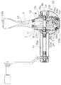
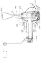
図1から図3において、本発明の一実施形態によるスピニングリールは、ハンドル1を有し、釣り竿に装着されるリール本体2と、リール本体2の前部に回転自在に装着されたロータ3と、ロータ3の前部に配置された前後移動するスプール4とを主に備えている。また、スピニングリールは、ハンドル1の回転に連動してロータ3を回転駆動するロータ駆動機構5と、ロータ3の回転に連動してスプール4を前後移動させるオシレーティング機構6とを備えている。
【0015】
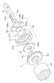
リール本体2は、内部にロータ駆動機構5とオシレーティング機構6とを収納している。リール本体2は、図1から図4に示すように、両側が開口する筐体部10と、筐体部10の両側をそれぞれ塞ぐ第1及び第2蓋部11,12と、筐体部10に一体形成された竿取付部13と、筐体部10及び両蓋部11,12を後方から覆うカバー部材14とを有している。
【0016】
筐体部10は、たとえば表面に陽極酸化被膜が形成されたマグネシウム合金製の軽量かつ比強度を維持可能な部材であり、ロータ駆動機構5やオシレーティング機構6を収納支持するための収納空間10aを形成し得る両面が開口した枠状の部材である。筐体部10は、奥行き(図3紙面直交方向)がほぼ同じ寸法で形成されたものである。筐体部10の前面には、逆転防止機構のワンウェイクラッチ(後述)やピニオンギア(後述)などが装着される円板状の機構支持部10bが形成されている。後部には、逆転防止機構の切換操作部(後述)が支持される操作支持部10cが形成されている。また、機構支持部10bの後方には、ピニオンギア及び切換操作部を支持するための中間支持部10dが上部から下方に向けて延びている。
【0017】
第1蓋部11は、比強度及び耐食性を高く維持可能なアルミニウム合金製の部材であり、筐体部10の一面を覆うように形成されている。第1蓋部11は、図2に示すように、マスターギア7に近接して配置されている。第1蓋部11は、図1及び図4から明らかなように、筐体部10の一面側の開口のうち、ハンドル1の回転により回転するマスターギア7を覆う第1カバー部11aと、第1カバー部11aから後方(図1に破線で示した部分より後方)の開口が露出する第2切欠き部11bとを有している。このような第2切欠き部11bを設けたのは、第1蓋部11とカバー部材14との重複部分を可及的に少なくして軽量化を図るためである。
【0018】
また、第1蓋部11には、図2及び図4に示すように、マスターギア7が設けられたマスターギア軸8の一端をマスターギア7の背面側で支持する第1ボス部11cが壁面の略中央部分に外方に突出して形成されている。また、第1蓋部11の前部には、ロータ3の内部に入り込む円板部を構成する略半円形の第1フランジ部11dが形成されている。第1フランジ部11dの前部には、機構支持部10bの後面に配置され機構支持部10bの外周面と略面一に構成される略半円弧状の第1機構収納カバー11eが形成されている。第1蓋部11にはマスターギア7が近接して配置されているため、マスターギア軸8に大きな負荷が作用したとき、第1ボス部11cには大きな力が作用しやすい。そこで、第1蓋部11は比強度を高く維持するために金属製にしてある。第1蓋部11の前下部には、カバー部材14を装着するとともに、洗浄時の水抜きやグリースの充填などのメンテナンスを行うための第1ねじ孔11fが形成されている。
【0019】
第2蓋部12は、第1蓋部11と略対称な鏡像関係の形状であり、第2カバー部12a、第2切欠き部12b、第2ボス部12c、第1フランジ部11dと略鏡像関係の形状の第2フランジ部12d、及び機構収納カバー12eが形成されている。また第2ねじ孔12f(図2)も第1ねじ孔11fと対向する位置に形成されている。第1及び第2フランジ部11d,12dは、筐体部10の機構支持部10b後面の外周面とで円形を構成するように形成されている。この円形部分がロータ3の後面に僅かな隙間ではまり込むように構成されている。第2蓋部12はマスターギア7から比較的遠くに配置されているため、第2ボス部12cには大きな力は作用しにくい。したがって、軽量化を図るために、たとえばナイロン66などの合成樹脂製としている。第2ボス部12cは、マスターギア軸8の他端を支持するために第2蓋部12の壁面の第1ボス部11cと対向する略中央部分に外方に突出して形成されている。
【0020】
なお、両蓋部11,12はたとえば丸頭ビスのような固定ねじ19により、筐体部10に固定されている。この蓋部11,12の固定方法は、種々の変形例が考えられ、たとえば、筐体部10を貫通させて一方の蓋部から他方の蓋部にねじ込むように固定してもよい。
竿取付部13は、筐体部10から上方に延びるT字形状の部材であり、先端に形成された前後に延びるリール脚13aが釣り竿にリールシート(図示せず)に装着可能である。なお、竿取付部13は軽量化及び肉厚の均一化を図るために上面及び前面に肉盗み部13b,13cがそれぞれ形成されている。
【0021】
カバー部材14は、第1及び第2蓋部11,12を装着した状態の筐体部10を後方から側部及び底部を覆うように湾曲して形成されている。カバー部材14は、第1及び第2蓋部11,12の後端部に形成された第1及び第2切欠き部11b,12bを塞ぐととも、リール本体2の後端角部を含む側面及び後面の傷付きを防止するために設けられている。カバー部材14は、ABS樹脂等の比較的硬質の合成樹脂製であり、表面に金属めっきを施している。カバー部材14は、前端側部の第1及び第2ねじ孔11e,12eに対向する位置に段付きのねじ装着孔14a,14bが形成されている。このねじ装着孔14a,14bに第1及び第2ねじ孔11f,12fにねじ込まれるねじ部材14cが装着されカバー部材14を両蓋部11,12に固定するとともにメンテナンス時にあけることができるようになっている。カバー部材14は後端下面で筐体部10の下面にねじ込まれる。ねじ部材14dによっても固定されている。
【0022】
このような構成のリール本体2では、第1蓋部11が軽量でかつ比強度が高いアルミニウム合金製であるので、マスターギア7が近接して配置され比較的大きな力が作用しやすい第1蓋部11の比強度を高く維持して軽量化を図ることができる。またマスターギア7から遠くあまり大きな力が作用しにくい第2蓋部12は合成樹脂を採用したので軽量化を図ることができる。さらに、筐体部10がマグネシウム合金製であるので、リール本体2全体として、比強度を維持して軽量化を図ることができる。
【0023】
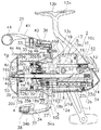
ロータ駆動機構5は、ハンドル1のハンドル軸1aがねじ込み固定されるマスターギア軸8と、マスターギア軸8に一体形成されたマスターギア7と、マスターギア7と噛み合うピニオンギア9とを備えている。
マスターギア軸8は、リール本体2の両蓋部11,12に形成された第1及び第2ボス部11c,12cに装着された軸受15a,15bによりリール本体2に回転自在に装着されている。マスターギア軸8の両端内周部には、雌ねじ部8a,8bがそれぞれ形成されている。雌ねじ部8a,8bは、ハンドル1を糸巻取方向に回転したときねじが締まる方向のねじである。したがって、図2左側の雌ねじ部8aは左ねじであり、右側の雌ねじ部8bは右ねじである。なお、ハンドル1は、図1及び図3に示す左位置と図2に示す右位置とのマスターギア軸8の両端の何れにも装着可能である。しかし、雌ねじ部8a,8bのねじ方向が異なるため、ハンドル軸1aを左右に取り付ける場合、それぞれ専用のものが用意されている。なお、図2には左ハンドル用のハンドル軸1aが図示されている。
【0024】
ピニオンギア9は、中空筒状の部材であり、前部がロータ3を貫通してロータ3を回転不能に装着している。ピニオンギア9の内周部には、スプール軸16が貫通して配置されている。ピニオンギア9の前部にはナット17が装着されており、ナット17によりロータ3がピニオンギア9に固定されている。ピニオンギア9は、その軸方向の中間部と後端部とがそれぞれ軸受18a,18bによりリール本体2の筐体部10に回転自在に支持されている。軸受18aは、機構支持部10bに装着され、軸受18bは、中間支持部10dに装着されている。ピニオンギア9の後端側に形成されたギア部9bには、環状の切欠き部9cが形成されている。この環状の切欠き部9cは、後述する減速機構20をコンパクトに配置するために設けられている。
【0025】
オシレーティング機構6は、図2及び図3に示すようにピニオンギア9に噛み合う減速機構20と、減速機構20に連動して回転する螺軸21と、螺軸21に係合して前後に往復移動するスライダ22と、スライダ22をスプール軸16方向に案内する2本のガイド軸23a,23bを有している。
減速機構20は、図5に示すように、ピニオンギア9に噛み合う大径ギア25a及び小径ギア25bを有する段付きギア部25と、小径ギア25bに噛み合う第1中間ギア26a及び第1中間ギア26aと間隔を隔てて配置された第2中間ギア26bとを有する中間軸26と、螺軸21に回転不能に装着され第2中間ギア26bに噛み合う従動ギア27とを備えている。
【0026】
段付きギア部25は、ピニオンギア9と平行な軸回りに回転する。大径ギア25aは、ピニオンギア9に噛み合うねじギアである。小径ギア25b、第1中間ギア26a、第2中間ギア26b及び従動ギア27は、ともにねじギアであり、中間軸26は、段付きギア部25と食い違う軸回りに回転し、従動ギア27が装着された螺軸21は、中間軸26と食い違いかつピニオンギア9と平行な軸回りに回転する。中間軸26の第2中間ギア26bは、ピニオンギア9の切欠き部9cの下方に配置されている。これにより、切欠き部を形成しない場合に比べて螺軸21をピニオンギア9に近接して配置させることができ、リール全体のコンパクト化を図ることができる。このような構成の減速機構20では、ピニオンギア9の回転が大きく減速されて螺軸21に伝達される。
【0027】
螺軸21は、表面に交差する螺旋状の溝21aが形成された部材であり、スプール軸16と平行に配置されている。螺軸21は、筐体部10の前後端にたとえば合成樹脂製の軸受を介して回転自在に装着されている。螺軸21は、筐体部10の後方から装着され、筐体部10の後面にねじ止め固定された固定板54により抜け止めされている。
【0028】
スライダ22は、内部に螺軸21の溝21aに係合する係合部材22aが装着されている。スライダ22は、スプール軸16の後端部に回転不能かつ移動不能に連結されている。スライダ22は、係合部材22aの先端が溝21aに係合することにより、螺軸21の回転に応じてスプール軸方向に往復移動し、スプール軸16をハンドル1の回転に連動して往復移動させる。
【0029】
ガイド軸23a,23bはスライダ22を貫通しており、スライダ22をスプール軸16に沿って案内する。ガイド軸23aは、筐体部10の後端と中間支持部10dとに両端が固定されている。ガイド軸23aは、筐体部10の後方から装着されており、螺軸21を抜け止めする固定板54により後端が抜け止めされている。ガイド軸23bは、筐体部10の前後端に両端が固定されている。ガイド軸23bは筐体部10の前方から装着されている。ガイド軸23bの前部には、第1蓋部11の前部を固定する固定ねじ19が接触可能であり、この固定ねじ19により抜け止めされている。
【0030】
ロータ3は、釣り糸案内部が一方のロータアームにのみ装着された、いわゆるベールレスタイプのものである。
ロータ3は、図3及び図6から図8に示すように、ピニオンギア9を介してリール本体2に回転自在に装着されたロータ本体30と、ロータ本体30に揺動自在に装着された釣り糸案内部31とを有している。
【0031】
ロータ本体30は、たとえば表面に陽極酸化被膜が形成されたマグネシウム合金製であり、筒状の支持部32と、支持部32の後端部外周面の対向する位置から支持部32と間隔を隔ててそれぞれ前方に延びる第1及び第2ロータアーム33,34とを有している。
支持部32は、後端から前方に向けてテーパ状に縮径した後に円筒状に形成された概ね筒状の部材である。支持部32の前部には、前壁32aが形成されており、前壁32aの中央部にはピニオンギア9の前部が貫通するボス部32bが形成されている。ボス部32bは、ピニオンギア9の前部に回転不能に装着されている。前壁32aの前部でピニオンギア9の前部にはナット17がねじ込まれており、このナット17によりロータ3がピニオンギア9に固定されている。また、支持部32の前部には、スプール軸16への釣り糸の巻き付きを防止するための筒状の糸噛み防止部材35が装着されている。
【0032】
第1ロータアーム33の先端には、釣り糸案内部31が糸巻取姿勢と糸開放姿勢とに揺動自在に装着されている。第1ロータアーム33の内部には、釣り糸案内部31の揺動に連動して動作する連動機構40が装着されている。第1ロータアーム33の径方向外周側は第1カバー部材36により覆われている。
第2ロータアーム34は、第1ロータアーム33と同様に前方に延びており、径方向外周側は、第2カバー部材37により覆われている。第2ロータアーム34は、ロータ3の回転バランスをとるために設けられたものである。このため、第2ロータアーム34は、釣り糸案内部31が装着された第1ロータアーム33の重心位置に近づけるために重心位置を前方側に偏倚させている。重心位置を前方側に偏倚させるために、第2ロータアーム34には基端側に開口部34aが形成されているとともに、先端側に重り38を装着するための重り収納部34bが形成されている。重り38は、たとえばタングステン合金製である。また、第2ロータアーム34は、重心を前方に偏倚させるために、図7及び図8から明らかなように、前方に延びる長さが第1ロータアーム33より長くなっている。
【0033】
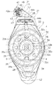
ここで、図6に示すように、第1ロータアーム33の釣り糸案内部31の揺動軸芯を通る第1直線L1と第2ロータアーム34の幅方向の中心を通りかつ第1直線L1と実質的に平行な第2直線L2とがロータ本体30の回転軸芯Xを挟んで逆側に略同じ距離だけ離れて配置されるように、両ロータアーム33,34は形成されている。このように両ロータアーム33,34を配置すると、釣り糸案内部31が回転軸芯Xに対して外側に偏倚(図6では第1直線L1に対して外側に偏倚)して配置されていても、回転バランスをさらに良好に維持することができる。
【0034】
糸噛み防止部材35は、支持部32の円筒部分と面一に形成された円筒状の噛み込み防止部35aと、噛み込み防止部35aの後端部に中心に向けて対向して設けられた1対の舌状の装着部35bとを有している。噛み込み防止部35aの先端は他の部分より大径に形成されており、これにより、スプール4内部に侵入した釣り糸がロータ3内に入らないようにしている。また、噛み込み防止部35aの先端内周面には、回転バランス補正用の重り39を収納するための重り収納部35cが形成されている。重り39も、たとえばタングステン合金製である。なお、重り収納部35cは、図3では、開示の便宜のため第2ロータアーム34に近接した位置に形成されているが、実際には、図6に示すように後述釣り糸案内部31が揺動する方向で両ロータアーム33,34の中間位置に配置されている。このように重り収納部35cを配置することにより、釣り糸案内部31が第1直線L1より回転軸芯Xからさらに離れる方向に偏倚して配置されていても、釣り糸案内部31に対して回転軸芯Xと逆側に配置された重り39により回転バランスを補正することができる。
【0035】
糸噛み防止部材35は、装着部35bの前面から装着された2本のねじ部材29,29により前壁32aに固定されている。なお、前壁32aの前面は糸噛み防止部材35を装着した状態で、装着部35bを含めて環状の平坦面となっている。装着部35bを含めた平坦面を前壁32aの前面に形成するために、前壁32aには、舌状の装着部35bが入り込む凹部32cが形成されている。これにより、スプール4側から異物が入り込んで付着しても、スプール4を外せば異物をふき取りなどして除去しやすい構造となっている。
【0036】
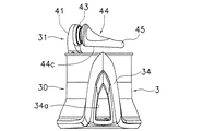
釣り糸案内部31は、図6〜図8に示すように、第1ロータアーム33の先端に装着された支持部材41と、支持部材41の先端に基端が固定された固定軸42と、固定軸42に回転自在に装着され釣り糸を案内可能なラインローラ43と、固定軸42の先端に設けられた固定軸カバー44と、固定軸カバー44の先端に設けられ釣り糸を係止する釣り糸係止部45とを有している。
【0037】
支持部材41は、先端に糸巻取姿勢と糸開放姿勢とに揺動自在に装着されている。固定軸42は、支持部材41の先端に基端が回転不能に係止され、取付ボルト42aにより支持部材41に固定される。固定軸42の外周には、ラインローラ43が1対の軸受46を介して回転自在に装着されている。ラインローラ43は、外周面に釣り糸を案内する環状の案内溝47が形成されており、糸ヨレが生じにくいようになっている。また、ラインローラ43の外周面の両端は、支持部材41及び固定軸カバー44により覆われている。
【0038】
固定軸カバー44は、固定軸42の先端に設けられ、固定軸の軸芯Y1より頂点44bが後方かつロータ3の回転中心側に向かって偏芯した略円錐形状の部材である。固定軸カバー44の後面側の稜線近傍の図7にハッチングで示す領域がラインローラ43に釣り糸を案内する釣り糸案内面44cとなっている。固定軸カバー44の前面には、他の部分より凹んだつまみ凹部44aが形成されている。このようなつまみ凹部44aを設けると釣り糸案内部31を糸巻取姿勢から糸開放姿勢に戻す際に便利である。釣り糸係止部45は、頂点44bの手前側で稜線と滑らかにと滑らかに連続して頂点44bから突出し先端が他の部分より太く形成されている。釣り糸係止部45の先端は球状に丸められている。
【0039】
このような構成の釣り糸案内部31は、釣り糸係止部45の先端が他の部分より太いので一度釣り糸が釣り糸係止部45に係止されると外れにくくなる。また、釣り糸係止部45及び固定軸カバー44の頂点44bが後方に傾いているので、釣り糸係止部45に係止された釣り糸が釣り糸案内面によりラインローラ43の案内溝47に確実に案内される。
【0040】
ロータ3は、図3に示すように、逆転防止機構50により糸繰り出し方向の回転を禁止・解除可能である。逆転防止機構50は、筐体部10の機構支持部10bに装着されたローラ型のワンウェイクラッチ51を有している。ワンウェイクラッチ51は、逆転禁止状態と逆転可能状態とに切換可能である。逆転防止機構50は、ワンウェイクラッチ51を逆転禁止状態と逆転可能状態とに切り換える切換操作部52をさらに有している。切換操作部52は、筐体部10の操作支持部10c及び中間支持部10dに揺動自在に支持されている。
【0041】
図9に示すように、スプール軸16の先端には、雄ねじ部16aと、互いに平行に切り欠かれた面取り部16bとが形成されており、スプール4は、雄ねじ部16aに螺合する着脱ナット55により、スプール軸16に回転不能かつ着脱自在に装着されている。
スプール4は、図3に示すように、浅溝形のものであり、外周に釣り糸が巻き付けられる糸巻き胴部4aと、糸巻き胴部4aの後端部に糸巻き胴部4aより大径に形成された筒状のスカート部4bと、糸巻き胴部4aの先端部に糸巻き胴部4aより僅かに大径に形成された前フランジ部4cとを備えている。
【0042】
糸巻き胴部4aは、スプール軸16に対して回転不能であり、ロータ3の支持部32及び糸噛み防止部材35の外周側に配置されている。糸巻き胴部4aは、先端側内周に一体形成された前壁部4dと、前壁部4dの内周側に後方に突出して一体形成されたボス部4eとを有している。前壁部4dには、軽量化を図るために多数の透孔4gが形成されている。
【0043】
ボス部4eは、図9に示すように、外形が正六角形の形状をしている。ボス部4eは、スプール軸16に回転自在に装着されており、取付部材56によりスプール軸16に回転不能に装着される。取付部材56は、ボス部4eを回転不能に係止するボス係止部材57と、ボス係止部材57をスプール軸16に対して回転不能にする係止部材58とを有している。ボス係止部材57は、ボス部4eと対向する前面57aに12角の星形断面の係止凹部57bを有しているとともに、後面57cに係止部材58に係合する4つの円形の係止突起57dを有している。係止部材58は、円板状の部材であり、スプール軸16の面取り部16bに係合するスリット58aを中心に有している。また、外周面に係止突起57dに係合する4つの係止溝58bを有している。面取り部16bにスリット58aをはめ込むことにより係止部材58はスプール軸16に回転不能に装着される。また、係止溝58bに係止突起57dを係止させることで、ボス係止部材57がスプール軸16に対して回転不能になる。なお、ボス係止部材57の係止凹部57bには、弾性体製のワッシャ部材59が装着されている。ワッシャ部材59は、スプール軸16の外形より僅かに小さい内径の孔部59aを有しており、孔部59aをスプール軸16に装着することにより、ボス係止部材57及び係止部材58のスプール軸16に対する前後移動を規制している。
【0044】
このような星形断面の係止凹部57bで六角形断面のボス部4eを係止させることにより、30度間隔の回転位相でスプール4をスプール軸16に回転不能に装着できる。これにより、着脱ナット55を緩めるだけでスプール4を回すことができ、ロータ3を回転させることなく仕掛けの垂らし長さを調整できる。
スカート部4bには、図1に示すように、軽量化を図るために内径が異なる多数の透孔4fが形成されている。前フランジ部4cには、糸巻き胴部4aの外周面から僅かに前方に拡径するテーパ状の外周面を有している。これによりキャスティング時に釣り糸に作用する放出抵抗が大きく減少する。
【0045】
次にスピニングリールの動作について説明する。
なお、動作の説明では右手でキャスティングする場合を説明する。キャスティングの際には、釣り糸案内部31を糸巻取姿勢にして釣り糸を釣り糸案内部31に引っ掛けた状態にして仕掛けの垂らし長さを調整する。
まずハンドル1を糸巻取方向に回してスプール4をストロークの最先端近くに配置した状態で釣り糸案内部31が所定の回転位相となるようにする。具体的には、釣り糸案内部31の操作のしやすさや釣り糸のつまみやすさを考慮し、たとえば、右手でキャスティングするときには釣り糸案内部31を釣り竿側から見てスプール4の左側に配置すると釣り糸案内部31を左手で操作しやすい。
【0046】
仕掛けの垂らし長さを変更する際には、着脱ナット55を緩めてスプール4を前方に移動させてボス部4eとボス係止部材57との係合を解除する。この状態でスプール4を回して仕掛けの垂らし長さを適当な位置に調整する。垂らし長さを調整したらスプール4を後方に移動させてボス部4eをボス係止部材57に係止させる。このとき、ボス部4eは30度毎にボス係止部材57に係合するので、仕掛けの垂らし長さを細かく調整できる。そして着脱ナット55を締めて垂らし長さの調整を終わる。
【0047】
この状態で左手(釣り竿を持つ手の逆の手)の指先で釣り糸案内部31の固定軸カバー44をつまんで釣り糸案内部31を糸開放姿勢に揺動させる。このとき、固定軸カバー44につまみ凹部44aが形成されているので、固定軸カバー44をつまみやすくなり、釣り糸案内部31をつまんで簡単に揺動させることができる。そして、スプール4に巻き付けられた釣り糸を、左手でつまんで釣り竿を右手の人差し指で引っ掛けてキャスティングする。
【0048】
キャスティングが終わると、左手で釣り糸案内部31を糸開放姿勢から糸巻取姿勢に戻し、左手で釣り糸をつまんで釣り糸案内部31の釣り糸係止部45に係止する。釣り糸係止部45に係止された釣り糸は、固定軸カバー44の釣り糸案内面44cを通ってラインローラ43の案内溝47に案内される。この状態でハンドル1を糸巻取方向に僅かに回転させて釣り糸にわずかにテンションをかけて置き竿する。
【0049】
仕掛けに獲物がかかってハンドル1を回すとロータ3が糸巻取方向に回転するとともにスプール4が前後移動する。このとき、ハンドル1の回転はマスターギア軸8を介してマスターギア7に伝達され、ピニオンギア9を介してロータ3が回転する。また、ピニオンギア9から減速機構20を介してオシレーティング機構6が動作してスプール4が前後移動する。この巻取時、獲物が大きくマスターギア7に大きな力が作用しても、マスターギア7が近接して配置された第1蓋部11は、アルミニウム合金製であるため、比強度を高く維持できる。しかも、第1蓋部12は合成樹脂製であり、筐体部10はマグネシウム合金製であるから軽量化を図ることができる。
【0050】
ここでは、第1蓋部11をたとえば金属のうちでも比重が小さい軽合金製にすることにより、マスターギア7が近接して配置され比較的大きな力が作用しやすい第1蓋部11の比強度を高く維持して軽量化を図ることができる。またマスターギア7から遠くあまり大きな力が作用しにくい第2蓋部12は合成樹脂を採用して軽量化を図ることができる。このため、リール本体2全体として、比強度を維持して軽量化を図ることができる。
【0051】
〔他の実施形態〕
(a)前記実施形態では、釣り糸案内部31がベールレス型のスピニングリールを例に本発明に係るリール本体を説明した。しかし、本発明は、釣り糸案内部が第1及び第2ロータアームの先端に揺動自在に装着された第1及び第2ベール支持部材と固定軸カバーと第2ベール支持部材とを連結するベールとを有する、いわゆるベールアームを有する一般的なスピニングリールのリール本体にも適用できる。
【0052】
(b)前記実施形態では、筐体部10をマグネシウム合金製としたが、筐体部10の材質はマグネシウム合金に限定されずアルミニウム合金やチタン合金などの軽量で比強度が高い金属やガラス繊維強化ナイロンや炭素繊維強化樹脂などの比強度が高く軽量な合成樹脂であってもよい。
(c)前記実施形態では、第1蓋部11の材質をアルミニウム合金製としたが、第1蓋部11の材質はチタン合金などの軽量で比強度が高い金属であればどのようなものでもよい。
【0053】
(d)前記実施形態では、竿取付部13を筐体部10と一体形成したが、図10に示すように、筐体部110ではなく第1蓋部111と竿取付部113とを一体形成してもよい。また、前記実施形態では、第1及び第2蓋部11,12にボス部11c,12cを設けてマスターギア軸を支持した。しかし、この実施形態では、マスターギア107が一体に形成されたマスターギア軸108を片持ち支持する筒状のボス部111cが第1蓋部111に設けられている。マスターギア軸108は、ボス部111cに間隔を隔てて配置された1対の軸受115a,115bによりボス部111cに回転自在に支持されている。この場合、第2蓋部112にはボス部が設けられていないため、滑らかな外観になる。
【0054】
【発明の効果】
本発明によれば、第1蓋部をたとえば金属のうちでも比重が小さい軽合金製にすることにより、マスターギアが近接して配置され比較的大きな力が作用しやすい第1蓋部の比強度を高く維持して軽量化を図ることができる。またマスターギアから遠くあまり大きな力が作用しにくい第2蓋部は合成樹脂を採用して軽量化を図ることができる。このため、リール本体全体として、比強度を維持して軽量化を図ることができる。
【図面の簡単な説明】
【図1】本発明の一実施形態を採用したスピニングリールの側面図。
【図2】そのスピニングリールの背面断面図。
【図3】そのスピニングリールの側面断面図。
【図4】リール本体の分解斜視図。
【図5】減速機構の斜視図。
【図6】ロータの正面図。
【図7】ロータの右側面図。
【図8】ロータの左側面図。
【図9】スプールの取付構造を示す分解斜視図。
【図10】他の実施形態の図2に相当する図。
【符号の説明】
1 ハンドル
2 リール本体
3 ロータ
4 スプール
7,107 マスターギア
8,108 マスターギア軸
10,110 筐体部
10a 収納空間
11,111 第1蓋部
11c 第1ボス部
12 第2蓋部
12c 第2ボス部
13 竿取付部
19 固定ねじ
111c ボス部
[0001]
TECHNICAL FIELD OF THE INVENTION
The present invention relates to a spinning reel reel that can be mounted on a reel body, particularly a fishing rod, and transmits the rotation of a handle to a line winding rotor and a line winding spool via a master gear to wind a fishing line onto the spool. Regarding the body.
[0002]
[Prior art]
As a reel body of the spinning reel, a rod mounting portion that can be mounted on a fishing rod, a housing portion integrally formed with the rod mounting portion, and first and second lid portions detachably mounted on both side portions of the housing portion. Is known (for example, see Patent Document 1).
[0003]
The housing is made of metal and maintains high strength. Various drive mechanisms such as a mechanism for rotating the rotor and a mechanism for moving the spool back and forth are mounted in the housing. The first and second lids are made of a synthetic resin having the same outer shape as or larger than the housing, and are configured to protect the housing. A rotation shaft (master gear shaft) of a master gear provided with a master gear is rotatably supported by the first and second lids. The master gear is arranged so as to be biased to one side of the master gear shaft with the spool shaft interposed therebetween, and is arranged, for example, close to the first lid.
[0004]
[Patent Document 1]
Japanese Utility Model Publication No. 54-172887.
[0005]
[Problems to be solved by the invention]
In recent spinning reels, in particular, spinning reels for throw fishing, it is required to maintain specific strength and reduce weight in order to facilitate casting. In the conventional three-part spinning reel reel body, since both lids supporting the master gear shaft are made of synthetic resin, the overall weight can be reduced. However, the specific strength of the reel body may not be sufficiently maintained. For example, when a large load is applied to apply a large load to the master gear, an excessive force may be applied to the first lid close to the master gear, and the first lid may be damaged.
[0006]
SUMMARY OF THE INVENTION An object of the present invention is to reduce the weight of a spinning reel having a three-part structure by maintaining a specific strength.
[0007]
[Means for Solving the Problems]
A spinning reel according to a first aspect of the present invention is a spinning reel that can be mounted on a fishing rod and that transmits rotation of a handle to a line winding rotor and a line winding spool via a master gear to wind a fishing line onto the spool. , Comprising a housing, a first lid, a second lid, and a rod mounting part. The housing portion can form a mechanism housing space for housing and supporting a drive mechanism for driving the spool and the rotor inside. The first lid portion is fixed to the housing portion so as to cover at least a part of one surface of the housing portion, and is formed of a metal in which a master gear is disposed close to and supports a rotation axis of the master gear on the back side of the master gear. belongs to. The second lid is made of a synthetic resin fixed to the housing so as to cover at least a part of the other surface of the housing. The rod attachment portion is formed integrally with either the housing portion or the first lid portion, and can be attached to the fishing rod.
[0008]
In the three-part reel body, the drive mechanism is supported in the mechanism storage space of the housing. One surface of the casing is covered with a first cover made of metal, and a master gear is arranged close to the first cover. The first cover supports a rotation axis of the master gear on the back side of the master gear. ing. Here, the first lid is made of, for example, a light alloy having a small specific gravity among metals, so that the master gear is arranged close to the first lid and a relatively large force is likely to act on a supporting portion thereof. The strength can be maintained high and the weight can be reduced. Further, the second lid portion, which is far from the master gear and does not easily exert a large force, can be made lightweight by employing a synthetic resin. For this reason, it is possible to reduce the weight of the entire reel body while maintaining the specific strength.
[0009]
A reel body of a spinning reel according to a second aspect of the present invention is the reel body according to the first aspect, wherein the first and second lids have first and second shaft supporting portions for supporting both ends of the rotating shaft of the master gear. Have. In this case, since the shaft supporting portions for supporting the ends of the rotating shaft of the master gear are provided on both lid portions, the handle can be mounted on either the left or right side of the reel body, and the rotating shaft of the master gear can be mounted. Since both ends are supported, the rigidity of the structure supporting the rotating shaft can be maintained high.
[0010]
The reel body of a spinning reel according to a third aspect of the present invention is the reel body according to the first aspect, wherein the first lid portion has a shaft support portion that cantileverly supports the rotating shaft of the master gear. In this case, since the rotating shaft of the master gear is cantilevered, the thickness of the reel body in the rotating shaft direction can be reduced. Further, since the rotating shaft does not penetrate the reel body, interference with the drive mechanism is reduced, and the arrangement of the drive mechanism is facilitated.
[0011]
A reel body of a spinning reel according to a fourth aspect of the present invention is the reel body according to any one of the first to third aspects, wherein the casing is made of a magnesium alloy, and the first lid is made of an aluminum alloy. In this case, since the housing is made of a magnesium alloy and the first lid is made of an aluminum alloy having a higher specific strength than the magnesium alloy, the specific strength can be maintained high and the weight can be further reduced. In addition, since both lid portions that are easily in contact with other components are less likely to corrode than the housing portion, the corrosion resistance can be improved.
[0012]
A spinning reel according to a fifth aspect of the present invention is the reel body according to any one of the first to fourth aspects, wherein the first and second lids are fixed to the housing with a plurality of screws, and at least one of the screws is provided. Is used for fixing the driving mechanism. In this case, since the drive mechanism is also fixed by screws for fixing the lid, the number of components can be reduced.
[0013]
A reel body of a spinning reel according to a sixth aspect of the present invention is the reel body according to any one of the first to fifth aspects, wherein the rod mounting portion is formed integrally with the housing. In this case, the right and left balance is improved because the housing and the rod mounting portion located at the center between the lids are integrally formed.
A reel body of a spinning reel according to a seventh aspect of the present invention is the reel body according to any one of the first to fifth aspects, wherein the rod mounting portion is formed integrally with the first lid portion. In this case, since the thick rod attachment portion is formed integrally with the first lid portion, the thickness change of the housing portion is reduced. For this reason, when the casing is formed of a resin or metal molded product, it is possible to easily prevent deformation such as sink marks due to thickness variation.
[0014]
BEST MODE FOR CARRYING OUT THE INVENTION
1 to 3, a spinning reel according to an embodiment of the present invention includes a reel body 2 having a handle 1 and mounted on a fishing rod, and a rotor 3 rotatably mounted on a front portion of the reel body 2. And a spool 4 which is disposed at the front of the rotor 3 and moves back and forth. The spinning reel also includes a rotor drive mechanism 5 that drives the rotor 3 to rotate in conjunction with the rotation of the handle 1 and an oscillating mechanism 6 that moves the spool 4 back and forth in conjunction with the rotation of the rotor 3.
[0015]
The reel body 2 houses a rotor drive mechanism 5 and an oscillating mechanism 6 inside. As shown in FIG. 1 to FIG. 4, the reel body 2 includes a casing 10 having openings on both sides, first and second lids 11 and 12 respectively closing both sides of the casing 10, and a casing 10. And a cover member 14 that covers the housing 10 and the lids 11 and 12 from behind.
[0016]
The housing portion 10 is a member made of, for example, a magnesium alloy having an anodic oxide film formed on its surface and capable of maintaining light weight and specific strength, and has a storage space 10 a for storing and supporting the rotor drive mechanism 5 and the oscillating mechanism 6. Is a frame-shaped member that is open on both sides. The housing section 10 is formed to have substantially the same depth (in the direction perpendicular to the plane of FIG. 3). On the front surface of the casing 10, a disk-shaped mechanism support portion 10b to which a one-way clutch (described later) or a pinion gear (described later) of a reverse rotation prevention mechanism is mounted is formed. At the rear, an operation support portion 10c is formed for supporting a switching operation portion (described later) of the reverse rotation prevention mechanism. An intermediate support portion 10d for supporting the pinion gear and the switching operation portion extends downward from the upper portion behind the mechanism support portion 10b.
[0017]
The first lid 11 is a member made of an aluminum alloy that can maintain high specific strength and corrosion resistance, and is formed so as to cover one surface of the housing 10. As shown in FIG. 2, the first lid 11 is arranged close to the master gear 7. As is clear from FIGS. 1 and 4, the first lid portion 11 includes a first cover portion 11 a that covers the master gear 7 that rotates by the rotation of the handle 1, among the openings on one surface side of the housing portion 10, And a second notch 11b from which the opening behind the cover 11a (the portion behind the portion shown by the broken line in FIG. 1) is exposed. The reason why the second notch 11b is provided is to reduce the overlapping portion of the first lid 11 and the cover member 14 as much as possible to reduce the weight.
[0018]
As shown in FIGS. 2 and 4, a first boss portion 11c supporting one end of a master gear shaft 8 provided with the master gear 7 on the back side of the master gear 7 is provided on the first lid portion 11. Is formed so as to protrude outward substantially at a central portion thereof. In addition, a substantially semicircular first flange portion 11d that forms a disk portion that enters the inside of the rotor 3 is formed at a front portion of the first lid portion 11. At the front of the first flange 11d, there is formed a substantially semicircular first mechanism housing cover 11e which is arranged on the rear surface of the mechanism support 10b and is substantially flush with the outer peripheral surface of the mechanism support 10b. I have. Since the master gear 7 is arranged close to the first lid portion 11, when a large load acts on the master gear shaft 8, a large force is likely to act on the first boss portion 11c. Therefore, the first lid 11 is made of metal in order to keep the specific strength high. At the front lower portion of the first lid portion 11, a first screw hole 11f for mounting the cover member 14 and performing maintenance such as drainage during cleaning and filling with grease is formed.
[0019]
The second lid portion 12 has a mirror image shape substantially symmetric with the first lid portion 11, and has a substantially mirror image with the second cover portion 12a, the second notch portion 12b, the second boss portion 12c, and the first flange portion 11d. A second flange portion 12d having a related shape and a mechanism housing cover 12e are formed. A second screw hole 12f (FIG. 2) is also formed at a position facing the first screw hole 11f. The first and second flange portions 11d and 12d are formed so as to form a circle with the outer peripheral surface of the rear surface of the mechanism support portion 10b of the housing portion 10. The circular portion is configured to fit into the rear surface of the rotor 3 with a slight gap. Since the second lid portion 12 is disposed relatively far from the master gear 7, a large force hardly acts on the second boss portion 12c. Therefore, in order to reduce the weight, it is made of synthetic resin such as nylon 66, for example. The second boss portion 12c is formed so as to protrude outward at a substantially central portion of the wall surface of the second lid portion 12 facing the first boss portion 11c in order to support the other end of the master gear shaft 8.
[0020]
The lids 11 and 12 are fixed to the housing 10 by fixing screws 19 such as round head screws. Various modifications are conceivable as a method of fixing the lids 11 and 12. For example, the lids 11 and 12 may be fixed so that the casing 10 is penetrated and screwed from one lid to the other lid.
The rod mounting part 13 is a T-shaped member extending upward from the housing part 10, and a front and rear extending reel leg 13a formed at the tip can be mounted on a fishing rod on a reel seat (not shown). The rod mounting portion 13 is provided with a thickness-removing portion 13b, 13c on the upper surface and the front surface, respectively, in order to reduce the weight and make the wall thickness uniform.
[0021]
The cover member 14 is formed to be curved so as to cover the side part and the bottom part from the rear of the housing part 10 with the first and second lid parts 11 and 12 attached. The cover member 14 covers the first and second notches 11b and 12b formed at the rear ends of the first and second lids 11 and 12, and also includes a side surface including the rear end corner of the reel body 2. And to prevent the rear surface from being damaged. The cover member 14 is made of a relatively hard synthetic resin such as an ABS resin, and has a surface plated with metal. The cover member 14 has stepped screw mounting holes 14a and 14b at positions facing the first and second screw holes 11e and 12e on the front end side. Screw members 14c to be screwed into the first and second screw holes 11f and 12f are mounted in the screw mounting holes 14a and 14b, so that the cover member 14 can be fixed to the lids 11 and 12 and can be opened at the time of maintenance. ing. The cover member 14 is screwed into the lower surface of the housing 10 at the lower surface of the rear end. It is also fixed by the screw member 14d.
[0022]
In the reel body 2 having such a configuration, since the first lid 11 is made of an aluminum alloy that is lightweight and has a high specific strength, the first lid 11 is disposed close to the first gear 11 and a relatively large force is likely to act thereon. The specific strength of the portion 11 can be maintained high to reduce the weight. Further, since the second lid portion 12 which is far from the master gear 7 and in which an excessively large force does not act is made of a synthetic resin, the weight can be reduced. Furthermore, since the housing 10 is made of a magnesium alloy, the specific strength of the entire reel body 2 can be maintained and the weight can be reduced.
[0023]
The rotor drive mechanism 5 includes a master gear shaft 8 into which the handle shaft 1a of the handle 1 is screwed and fixed, a master gear 7 integrally formed with the master gear shaft 8, and a pinion gear 9 meshing with the master gear 7. .
The master gear shaft 8 is rotatably mounted on the reel body 2 by bearings 15a and 15b mounted on first and second bosses 11c and 12c formed on both lids 11 and 12 of the reel body 2. . Internal thread portions 8a and 8b are formed on inner peripheral portions of both ends of the master gear shaft 8, respectively. The female screw portions 8a and 8b are screws in a direction in which the screws are tightened when the handle 1 is rotated in the line winding direction. Accordingly, the female screw portion 8a on the left side in FIG. 2 is a left-handed screw, and the female screw portion 8b on the right-hand side is a right-handed screw. Note that the handle 1 can be attached to both ends of the master gear shaft 8 at the left position shown in FIGS. 1 and 3 and the right position shown in FIG. However, since the screw directions of the female screw portions 8a and 8b are different, when the handle shaft 1a is mounted on the left and right, dedicated ones are prepared. FIG. 2 shows a handle shaft 1a for the left handle.
[0024]
The pinion gear 9 is a hollow cylindrical member, and has a front portion that penetrates through the rotor 3 and non-rotatably mounts the rotor 3. A spool shaft 16 penetrates an inner peripheral portion of the pinion gear 9. A nut 17 is mounted on a front portion of the pinion gear 9, and the rotor 3 is fixed to the pinion gear 9 by the nut 17. The pinion gear 9 has an axial middle portion and a rear end portion rotatably supported by the housing 10 of the reel unit 2 by bearings 18a and 18b, respectively. The bearing 18a is mounted on the mechanism support 10b, and the bearing 18b is mounted on the intermediate support 10d. An annular notch 9c is formed in a gear portion 9b formed on the rear end side of the pinion gear 9. The annular notch 9c is provided for compactly disposing a reduction mechanism 20 described later.
[0025]
2 and 3, the oscillating mechanism 6 engages with the pinion gear 9, a screw shaft 21 that rotates in conjunction with the speed reducing mechanism 20, and reciprocates back and forth by engaging with the screw shaft 21. It has a slider 22 that moves and two guide shafts 23a and 23b that guide the slider 22 in the direction of the spool shaft 16.
As shown in FIG. 5, the reduction mechanism 20 includes a stepped gear portion 25 having a large-diameter gear 25a and a small-diameter gear 25b that mesh with the pinion gear 9, a first intermediate gear 26a and a first intermediate gear 26a that mesh with the small-diameter gear 25b. And an intermediate shaft 26 having a second intermediate gear 26b arranged at an interval, and a driven gear 27 which is non-rotatably mounted on the screw shaft 21 and meshes with the second intermediate gear 26b.
[0026]
The stepped gear portion 25 rotates around an axis parallel to the pinion gear 9. The large-diameter gear 25a is a screw gear that meshes with the pinion gear 9. The small-diameter gear 25b, the first intermediate gear 26a, the second intermediate gear 26b, and the driven gear 27 are all threaded gears. The intermediate shaft 26 rotates around an axis that is different from the stepped gear portion 25, and the driven gear 27 is mounted. The helical shaft 21 is rotated about an axis that is offset from the intermediate shaft 26 and parallel to the pinion gear 9. The second intermediate gear 26 b of the intermediate shaft 26 is arranged below the cutout 9 c of the pinion gear 9. Thus, the screw shaft 21 can be arranged closer to the pinion gear 9 than when the notch portion is not formed, and the whole reel can be made compact. In the speed reduction mechanism 20 having such a configuration, the rotation of the pinion gear 9 is greatly reduced and transmitted to the screw shaft 21.
[0027]
The screw shaft 21 is a member in which a spiral groove 21 a crossing the surface is formed, and is arranged in parallel with the spool shaft 16. The screw shaft 21 is rotatably mounted on the front and rear ends of the housing 10 via, for example, a bearing made of synthetic resin. The screw shaft 21 is mounted from the rear of the housing unit 10 and is prevented from coming off by a fixing plate 54 fixed to the rear surface of the housing unit 10 with screws.
[0028]
The slider 22 has an engagement member 22a that engages with the groove 21a of the screw shaft 21 inside. The slider 22 is non-rotatably and immovably connected to the rear end of the spool shaft 16. The slider 22 reciprocates in the spool axis direction in accordance with the rotation of the screw shaft 21 by engaging the tip of the engaging member 22a with the groove 21a, and reciprocates the spool shaft 16 in conjunction with the rotation of the handle 1. Let it.
[0029]
The guide shafts 23a and 23b pass through the slider 22, and guide the slider 22 along the spool shaft 16. Both ends of the guide shaft 23a are fixed to the rear end of the housing 10 and the intermediate support 10d. The guide shaft 23 a is mounted from the rear of the housing 10, and the rear end of the guide shaft 23 a is prevented by a fixing plate 54 that prevents the screw shaft 21 from coming off. Both ends of the guide shaft 23 b are fixed to the front and rear ends of the housing 10. The guide shaft 23b is mounted from the front of the housing 10. A fixing screw 19 for fixing the front part of the first lid part 11 can be in contact with the front part of the guide shaft 23b, and the fixing screw 19 prevents the screw from coming off.
[0030]
The rotor 3 is a so-called bailless type in which a fishing line guide is mounted on only one rotor arm.
As shown in FIGS. 3 and 6 to 8, the rotor 3 includes a rotor body 30 rotatably mounted on the reel body 2 via a pinion gear 9, and a fishing line rotatably mounted on the rotor body 30. And a guide portion 31.
[0031]
The rotor body 30 is made of, for example, a magnesium alloy having an anodic oxide film formed on the surface thereof, and is spaced apart from the cylindrical support portion 32 by a distance from the position opposite the outer peripheral surface of the rear end of the support portion 32. And first and second rotor arms 33 and 34 extending forward, respectively.
The support part 32 is a substantially cylindrical member formed into a cylindrical shape after reducing the diameter in a tapered shape from the rear end toward the front. A front wall 32a is formed at a front portion of the support portion 32, and a boss portion 32b through which a front portion of the pinion gear 9 penetrates is formed at a central portion of the front wall 32a. The boss 32b is non-rotatably mounted on the front of the pinion gear 9. A nut 17 is screwed into a front portion of the pinion gear 9 at a front portion of the front wall 32a, and the rotor 3 is fixed to the pinion gear 9 by the nut 17. In addition, a tubular line biting prevention member 35 for preventing the fishing line from being wound around the spool shaft 16 is attached to a front portion of the support portion 32.
[0032]
At the tip of the first rotor arm 33, a fishing line guide portion 31 is swingably mounted in a line winding position and a line releasing position. An interlocking mechanism 40 that operates in conjunction with the swing of the fishing line guide 31 is mounted inside the first rotor arm 33. The radially outer peripheral side of the first rotor arm 33 is covered by a first cover member 36.
The second rotor arm 34 extends forward like the first rotor arm 33, and the radially outer peripheral side is covered by a second cover member 37. The second rotor arm 34 is provided to balance the rotation of the rotor 3. For this reason, the second rotor arm 34 shifts its center of gravity forward so as to approach the center of gravity of the first rotor arm 33 on which the fishing line guide 31 is mounted. In order to shift the center of gravity forward, the second rotor arm 34 has an opening 34a at the base end and a weight storage portion 34b at the tip end for mounting the weight 38. I have. The weight 38 is made of, for example, a tungsten alloy. 7 and 8, the second rotor arm 34 has a longer frontward extension than the first rotor arm 33 so as to shift the center of gravity forward.
[0033]
Here, as shown in FIG. 6, a first straight line L1 passing through the swing axis of the fishing line guide portion 31 of the first rotor arm 33 and a first straight line L1 passing through the center in the width direction of the second rotor arm 34 are defined. The two rotor arms 33 and 34 are formed such that the substantially parallel second straight line L2 is disposed on the opposite side of the rotation axis X of the rotor body 30 on the opposite side by substantially the same distance. When the two rotor arms 33 and 34 are arranged in this manner, even if the fishing line guide portion 31 is arranged to be deviated outward with respect to the rotation axis X (in FIG. 6, it is deviated outward with respect to the first straight line L1). In addition, the rotation balance can be maintained more favorably.
[0034]
The thread bite prevention member 35 is provided to face the center of the rear end of the bite prevention portion 35a and a cylindrical bite prevention portion 35a formed flush with the cylindrical portion of the support portion 32. And a pair of tongue-shaped mounting portions 35b. The tip of the biting prevention portion 35a is formed to have a larger diameter than other portions, thereby preventing the fishing line that has entered the inside of the spool 4 from entering the rotor 3. A weight storage portion 35c for storing the rotation balance correction weight 39 is formed on the inner peripheral surface of the distal end of the biting prevention portion 35a. The weight 39 is also made of, for example, a tungsten alloy. In FIG. 3, the weight storage portion 35c is formed at a position close to the second rotor arm 34 for convenience of disclosure, but in actuality, as shown in FIG. It is arranged at an intermediate position between the two rotor arms 33 and 34 in the moving direction. By arranging the weight accommodating portion 35c in this manner, even if the fishing line guide portion 31 is arranged so as to be deviated further away from the rotation axis X than the first straight line L1, the rotation shaft is positioned with respect to the fishing line guide portion 31. The rotation balance can be corrected by the weight 39 disposed on the side opposite to the core X.
[0035]
The thread biting prevention member 35 is fixed to the front wall 32a by two screw members 29, 29 mounted from the front of the mounting portion 35b. In addition, the front surface of the front wall 32a is an annular flat surface including the mounting portion 35b in a state where the thread bite prevention member 35 is mounted. In order to form a flat surface including the mounting portion 35b on the front surface of the front wall 32a, a concave portion 32c into which the tongue-shaped mounting portion 35b enters is formed in the front wall 32a. Thus, even if foreign matter enters and adheres from the spool 4 side, if the spool 4 is removed, the foreign matter is easily wiped off and removed.
[0036]
As shown in FIGS. 6 to 8, the fishing line guide portion 31 includes a support member 41 attached to the distal end of the first rotor arm 33, a fixed shaft 42 having a proximal end fixed to the distal end of the support member 41, A line roller 43 rotatably mounted on the shaft 42 and capable of guiding the fishing line, a fixed shaft cover 44 provided at the tip of the fixed shaft 42, and a fishing line hook provided at the tip of the fixed shaft cover 44 to lock the fishing line And a part 45.
[0037]
The support member 41 is swingably mounted at the tip end in a yarn winding posture and a yarn releasing posture. The base end of the fixed shaft 42 is non-rotatably locked to the distal end of the support member 41, and is fixed to the support member 41 by a mounting bolt 42a. A line roller 43 is rotatably mounted on the outer periphery of the fixed shaft 42 via a pair of bearings 46. An annular guide groove 47 for guiding the fishing line is formed on the outer peripheral surface of the line roller 43, so that the line is hardly twisted. Both ends of the outer peripheral surface of the line roller 43 are covered with the support member 41 and the fixed shaft cover 44.
[0038]
The fixed shaft cover 44 is a substantially conical member that is provided at the tip of the fixed shaft 42, and whose vertex 44 b is eccentric toward the rotation center side of the rotor 3 behind the axis Y 1 of the fixed shaft. A region shown by hatching in FIG. 7 near the ridgeline on the rear surface side of the fixed shaft cover 44 is a fishing line guide surface 44 c for guiding the fishing line to the line roller 43. On the front surface of the fixed shaft cover 44, a knob recess 44a that is recessed from other portions is formed. Providing such a knob concave portion 44a is convenient for returning the fishing line guide portion 31 from the line winding position to the line releasing position. The fishing line engaging portion 45 projects from the apex 44b smoothly and smoothly continuously with the ridge line on the near side of the apex 44b, and the tip is formed thicker than other portions. The tip of the fishing line engaging portion 45 is rounded in a spherical shape.
[0039]
In the fishing line guide portion 31 having such a configuration, since the tip of the fishing line locking portion 45 is thicker than other portions, it is difficult for the fishing line to come off once the fishing line is locked to the fishing line locking portion 45. Further, since the fishing line locking portion 45 and the apex 44b of the fixed shaft cover 44 are inclined rearward, the fishing line locked by the fishing line locking portion 45 is reliably guided to the guide groove 47 of the line roller 43 by the fishing line guide surface. Is done.
[0040]
As shown in FIG. 3, the rotation of the rotor 3 in the line feeding direction can be prohibited or released by the reverse rotation prevention mechanism 50. The reverse rotation prevention mechanism 50 has a roller-type one-way clutch 51 mounted on the mechanism support portion 10b of the housing portion 10. One-way clutch 51 is switchable between a reverse rotation prohibited state and a reverse rotation enabled state. The reverse rotation prevention mechanism 50 further includes a switching operation unit 52 that switches the one-way clutch 51 between a reverse rotation prohibited state and a reverse rotation enabled state. The switching operation section 52 is swingably supported by the operation support section 10c and the intermediate support section 10d of the housing section 10.
[0041]
As shown in FIG. 9, a male screw portion 16a and a chamfered portion 16b cut out in parallel with each other are formed at the tip of the spool shaft 16, and the spool 4 is provided with a detachable nut screwed into the male screw portion 16a. By 55, it is non-rotatably and detachably attached to the spool shaft 16.
As shown in FIG. 3, the spool 4 has a shallow groove shape, and has a bobbin trunk 4a around which a fishing line is wound, and a rear end of the bobbin trunk 4a formed with a larger diameter than the bobbin trunk 4a. A cylindrical skirt portion 4b and a front flange portion 4c formed at the tip of the bobbin trunk 4a with a slightly larger diameter than the bobbin trunk 4a.
[0042]
The bobbin trunk 4 a is not rotatable with respect to the spool shaft 16, and is disposed on the outer peripheral side of the support portion 32 of the rotor 3 and the thread bite preventing member 35. The bobbin trunk 4a has a front wall 4d integrally formed on the inner periphery on the distal end side, and a boss 4e integrally formed by projecting rearward on the inner periphery of the front wall 4d. A large number of through holes 4g are formed in the front wall 4d to reduce the weight.
[0043]
As shown in FIG. 9, the boss 4e has a regular hexagonal outer shape. The boss 4 e is rotatably mounted on the spool shaft 16 and is non-rotatably mounted on the spool shaft 16 by the mounting member 56. The mounting member 56 has a boss locking member 57 that locks the boss portion 4 e so as not to rotate, and a locking member 58 that locks the boss locking member 57 with respect to the spool shaft 16. The boss locking member 57 has a locking concave portion 57b having a dodecagonal star-shaped cross section on the front surface 57a facing the boss portion 4e, and four circular engagement members engaging with the locking member 58 on the rear surface 57c. It has a stop projection 57d. The locking member 58 is a disk-shaped member, and has a slit 58a that engages with the chamfered portion 16b of the spool shaft 16 at the center. Further, the outer peripheral surface has four locking grooves 58b that engage with the locking projections 57d. The locking member 58 is non-rotatably mounted on the spool shaft 16 by fitting the slit 58a into the chamfered portion 16b. Further, by locking the locking projection 57d in the locking groove 58b, the boss locking member 57 cannot rotate with respect to the spool shaft 16. In addition, a washer member 59 made of an elastic body is mounted on the locking concave portion 57b of the boss locking member 57. The washer member 59 has a hole 59 a having an inner diameter slightly smaller than the outer shape of the spool shaft 16, and the spool 59 of the boss locking member 57 and the locking member 58 is mounted by mounting the hole 59 a on the spool shaft 16. The forward and backward movement with respect to the shaft 16 is regulated.
[0044]
By locking the boss portion 4e having a hexagonal cross section with the locking concave portion 57b having such a star cross section, the spool 4 can be non-rotatably mounted on the spool shaft 16 at a rotation phase of 30 degrees. Thus, the spool 4 can be turned only by loosening the detachable nut 55, and the hanging length of the device can be adjusted without rotating the rotor 3.
As shown in FIG. 1, a large number of through holes 4f having different inner diameters are formed in the skirt portion 4b to reduce the weight. The front flange portion 4c has a tapered outer peripheral surface that slightly increases in diameter from the outer peripheral surface of the bobbin trunk 4a. This greatly reduces the emission resistance acting on the fishing line during casting.
[0045]
Next, the operation of the spinning reel will be described.
In the description of the operation, the case of casting with the right hand will be described. At the time of casting, the fishing line guide portion 31 is set in the line winding position, and the hanging length of the tackle is adjusted while the fishing line is hooked on the fishing line guide portion 31.
First, the steering line 1 is turned in the line winding direction, and the fishing line guide portion 31 is set to have a predetermined rotation phase in a state where the spool 4 is arranged near the leading end of the stroke. Specifically, in consideration of the ease of operation of the fishing line guide portion 31 and the ease of pinching the fishing line, for example, when casting with the right hand, the fishing line guide portion 31 may be disposed on the left side of the spool 4 when viewed from the fishing rod side. It is easy to operate the unit 31 with the left hand.
[0046]
When changing the hanging length of the device, the detachable nut 55 is loosened and the spool 4 is moved forward to release the engagement between the boss portion 4e and the boss locking member 57. In this state, the spool 4 is turned to adjust the hanging length of the device to an appropriate position. After adjusting the hanging length, the spool 4 is moved rearward to lock the boss 4e with the boss locking member 57. At this time, the boss portion 4e engages with the boss locking member 57 every 30 degrees, so that the hanging length of the device can be finely adjusted. Then, the attachment / detachment nut 55 is tightened, and the hanging length adjustment is completed.
[0047]
In this state, the fixed shaft cover 44 of the fishing line guide portion 31 is pinched with the fingertip of the left hand (the opposite hand of the hand holding the fishing rod) to swing the fishing line guide portion 31 to the line releasing position. At this time, since the fixed shaft cover 44 is formed with the knob concave portion 44a, the fixed shaft cover 44 is easily pinched, and the fishing line guide portion 31 can be pinched and easily swung. Then, the fishing line wound around the spool 4 is pinched with the left hand and the fishing rod is hooked with the forefinger of the right hand for casting.
[0048]
When the casting is completed, the fishing line guide portion 31 is returned from the line releasing position to the line winding position with the left hand, and the fishing line is pinched with the left hand and locked in the fishing line locking portion 45 of the fishing line guide portion 31. The fishing line locked by the fishing line locking portion 45 is guided to the guide groove 47 of the line roller 43 through the fishing line guide surface 44 c of the fixed shaft cover 44. In this state, the handle 1 is slightly rotated in the line winding direction to slightly apply tension to the fishing line, and the fishing line is put on the fishing line.
[0049]
When the handle 1 is turned with the catch on the device, the rotor 3 rotates in the line winding direction and the spool 4 moves back and forth. At this time, the rotation of the handle 1 is transmitted to the master gear 7 via the master gear shaft 8, and the rotor 3 rotates via the pinion gear 9. Further, the oscillating mechanism 6 operates from the pinion gear 9 via the speed reduction mechanism 20 to move the spool 4 back and forth. At the time of this winding, even if the prey is large and a large force acts on the master gear 7, the first lid portion 11 in which the master gear 7 is disposed in close proximity can be maintained at a high specific strength because it is made of an aluminum alloy. . Moreover, the first lid 12 is made of a synthetic resin, and the housing 10 is made of a magnesium alloy, so that the weight can be reduced.
[0050]
Here, the first cover 11 is made of, for example, a light alloy having a small specific gravity among metals, so that the master gear 7 is arranged close to the first cover 11 and a relatively large force is easily applied to the first cover 11. Can be kept high to reduce the weight. Further, the second lid portion 12 far from the master gear 7 and in which a very large force does not easily act can be made of synthetic resin to reduce the weight. For this reason, the weight of the entire reel body 2 can be reduced while maintaining the specific strength.
[0051]
[Other embodiments]
(A) In the above-described embodiment, the reel body according to the present invention has been described with the fishing line guide 31 as an example of a baleless type spinning reel. However, according to the present invention, the bail connecting the first and second bail support members, the fixed shaft cover, and the second bail support member, in which the fishing line guide portion is swingably attached to the tips of the first and second rotor arms, is provided. This is also applicable to a reel body of a general spinning reel having a so-called bail arm.
[0052]
(B) In the above-described embodiment, the casing 10 is made of a magnesium alloy. However, the material of the casing 10 is not limited to the magnesium alloy, and is a light weight metal having a high specific strength, such as an aluminum alloy or a titanium alloy, or a glass fiber. Lightweight synthetic resin having high specific strength such as reinforced nylon or carbon fiber reinforced resin may be used.
(C) In the above embodiment, the material of the first lid 11 is made of an aluminum alloy. However, the material of the first lid 11 may be any material such as a titanium alloy as long as it is lightweight and has high specific strength. Good.
[0053]
(D) In the above embodiment, the rod mounting portion 13 is formed integrally with the housing portion 10. However, as shown in FIG. 10, the first lid portion 111 and the rod mounting portion 113 are formed integrally instead of the housing portion 110. May be. In the above-described embodiment, the boss portions 11c and 12c are provided on the first and second lid portions 11 and 12 to support the master gear shaft. However, in this embodiment, the first lid portion 111 is provided with a cylindrical boss portion 111c that cantileverly supports the master gear shaft 108 integrally formed with the master gear 107. The master gear shaft 108 is rotatably supported by the boss 111c by a pair of bearings 115a and 115b arranged at a distance from the boss 111c. In this case, since the boss is not provided on the second lid 112, the second lid 112 has a smooth appearance.
[0054]
【The invention's effect】
According to the present invention, the first cover is made of, for example, a light alloy having a small specific gravity among metals, so that the master gear is arranged close to the first cover and a relatively large force is easily applied to the first cover. Can be kept high to reduce the weight. Further, the second lid portion, which is far from the master gear and does not easily exert a large force, can be made lightweight by employing a synthetic resin. For this reason, it is possible to reduce the weight of the entire reel body while maintaining the specific strength.
[Brief description of the drawings]
FIG. 1 is a side view of a spinning reel employing one embodiment of the present invention.
FIG. 2 is a rear sectional view of the spinning reel.
FIG. 3 is a side sectional view of the spinning reel.
FIG. 4 is an exploded perspective view of the reel body.
FIG. 5 is a perspective view of a speed reduction mechanism.
FIG. 6 is a front view of a rotor.
FIG. 7 is a right side view of the rotor.
FIG. 8 is a left side view of the rotor.
FIG. 9 is an exploded perspective view showing a mounting structure of the spool.
FIG. 10 is a diagram corresponding to FIG. 2 of another embodiment.
[Explanation of symbols]
DESCRIPTION OF SYMBOLS 1 Handle 2 Reel body 3 Rotor 4 Spool 7, 107 Master gear 8, 108 Master gear shaft 10, 110 Housing part 10a Storage space 11, 111 First lid part 11c First boss part 12 Second lid part 12c Second boss Part 13 Rod mounting part 19 Fixing screw 111c Boss part

Claims (7)

釣り竿に装着可能であり、マスターギアを介してハンドルの回転をロータ及び糸巻用のスプールに伝達して釣り糸を前記スプールに巻き取るスピニングリールのリール本体であって、
内部に前記スプール及び前記ロータを駆動する駆動機構を収納支持するための機構収納空間を形成し得る筐体部と、
前記筐体部の一面の少なくとも一部を覆うように前記筐体部に固定され、前記マスターギアが近接して配置され前記マスターギアの背面側で前記マスターギアの回転軸を支持する金属製の第1蓋部と、
前記筐体部の他面の少なくとも一部を覆うように前記筐体部に固定される合成樹脂製の第2蓋部と、
前記筐体部及び第1蓋部のいずれかに一体形成され、前記釣り竿に取付可能な竿取付部と、
を備えたスピニングリールのリール本体。
A spinning reel reel body that can be attached to a fishing rod, transmits the rotation of a handle to a rotor and a spool for spooling through a master gear, and winds a fishing line around the spool,
A housing part capable of forming a mechanism housing space for housing and supporting a drive mechanism for driving the spool and the rotor therein;
A metal member fixed to the housing portion so as to cover at least a part of one surface of the housing portion, wherein the master gear is disposed close to and supports a rotation axis of the master gear on the back side of the master gear. A first lid,
A second lid made of a synthetic resin fixed to the housing so as to cover at least a part of the other surface of the housing,
A rod attachment portion integrally formed on one of the housing portion and the first lid portion and attachable to the fishing rod;
Reel body of spinning reel equipped with.
前記第1及び第2蓋部は、前記マスターギアの回転軸の両端部をそれぞれ支持する第1及び第2軸支持部を有する、請求項1に記載のスピニングリールのリール本体。2. The reel body of a spinning reel according to claim 1, wherein the first and second lids have first and second shaft supports that respectively support both ends of a rotation shaft of the master gear. 3. 前記第1蓋部は、前記マスターギアの回転軸を片持ち支持する軸支持部を有する、請求項1に記載のスピニングリールのリール本体。2. The reel body of the spinning reel according to claim 1, wherein the first cover has a shaft support that cantileverly supports a rotation shaft of the master gear. 3. 前記筐体部はマグネシウム合金製であり、前記第1蓋部はアルミニウム合金製である、請求項1から3のいずれかに記載のスピニングリールのリール本体。The reel body of a spinning reel according to any one of claims 1 to 3, wherein the casing is made of a magnesium alloy, and the first lid is made of an aluminum alloy. 前記第1及び第2蓋部は、前記筐体部に複数本のビスにより固定され、
前記ビスの少なくともひとつは、前記駆動機構の固定に用いられる、請求項1から4のいずれかに記載のスピニングリールのリール本体。
The first and second lids are fixed to the housing with a plurality of screws,
The reel body of a spinning reel according to any one of claims 1 to 4, wherein at least one of the screws is used for fixing the driving mechanism.
前記竿取付部は、前記筐体部と一体形成されている、請求項1から5のいずれかに記載のスピニングリールのリール本体。The reel body of a spinning reel according to any one of claims 1 to 5, wherein the rod attachment portion is formed integrally with the housing portion. 前記竿取付部は、前記第1蓋部と一体形成されている、請求項1から5のいずれかに記載のスピニングリールのリール本体。The reel body of a spinning reel according to any one of claims 1 to 5, wherein the rod attachment part is formed integrally with the first lid part.
JP2003028470A 2003-02-05 2003-02-05 Reel body of spinning reel Pending JP2004236567A (en)

Priority Applications (10)

Application Number Priority Date Filing Date Title
JP2003028470A JP2004236567A (en) 2003-02-05 2003-02-05 Reel body of spinning reel
SG200400621A SG121863A1 (en) 2003-02-05 2004-01-27 Reel unit for spinning reel
US10/764,587 US7028937B2 (en) 2003-02-05 2004-01-27 Reel unit for spinning reel
DE602004000480T DE602004000480T2 (en) 2003-02-05 2004-01-31 fishing reel
AT04250538T ATE320178T1 (en) 2003-02-05 2004-01-31 FISHING WINCH
EP04250538A EP1444892B1 (en) 2003-02-05 2004-01-31 Reel unit for a spinning reel
TW093102324A TWI308479B (en) 2003-02-05 2004-02-02 Reel unit for spinning reel
KR1020040006912A KR101080067B1 (en) 2003-02-05 2004-02-03 Reel unit for spinning reel
MYPI20040328A MY128881A (en) 2003-02-05 2004-02-04 Reel unit for spinning reel
CNB200410004019XA CN100429973C (en) 2003-02-05 2004-02-05 Reel master of spinning reel

Applications Claiming Priority (1)

Application Number Priority Date Filing Date Title
JP2003028470A JP2004236567A (en) 2003-02-05 2003-02-05 Reel body of spinning reel

Publications (2)

Publication Number Publication Date
JP2004236567A true JP2004236567A (en) 2004-08-26
JP2004236567A5 JP2004236567A5 (en) 2006-03-23

Family

ID=32955936

Family Applications (1)

Application Number Title Priority Date Filing Date
JP2003028470A Pending JP2004236567A (en) 2003-02-05 2003-02-05 Reel body of spinning reel

Country Status (1)

Country Link
JP (1) JP2004236567A (en)

Similar Documents

Publication Publication Date Title
JP2004236568A (en) Reel body of spinning reel
JP4804279B2 (en) Spinning reel
JP2004236571A (en) Handle fixing structure of fishing reel
JP2004222525A (en) Handle assembly of spinning reel
EP1444892B1 (en) Reel unit for a spinning reel
JP2004357692A (en) Master gear of spinning reel
KR101081844B1 (en) Rotor for spinning reel
JP2004236567A (en) Reel body of spinning reel
JP4121871B2 (en) Spinning reel body
JP2004236570A (en) Rotor for spinning reel
JP2004236565A (en) Rotor of spinning reel
JP2001231414A (en) Handle assembly of spinning reel
JP2004236569A (en) Rotor for spinning reel
JP4078221B2 (en) Spinning reel rotor
JP4078222B2 (en) Spinning reel rotor rotation regulating device
JP2004236564A (en) Rotor of spinning reel
JP2000060375A (en) Attached structure of bail supporting member for spinning reel
JP2004141040A (en) Handle assembly of spinning reel
JP2003284464A (en) Handle-attaching structure of fishing reel

Legal Events

Date Code Title Description
A521 Written amendment

Free format text: JAPANESE INTERMEDIATE CODE: A523

Effective date: 20060125

A621 Written request for application examination

Effective date: 20060125

Free format text: JAPANESE INTERMEDIATE CODE: A621

A977 Report on retrieval

Free format text: JAPANESE INTERMEDIATE CODE: A971007

Effective date: 20071004

A131 Notification of reasons for refusal

Free format text: JAPANESE INTERMEDIATE CODE: A131

Effective date: 20071113

A02 Decision of refusal

Effective date: 20080311

Free format text: JAPANESE INTERMEDIATE CODE: A02