【0001】
【発明の属する技術分野】
本発明は、無線基地局およびこの無線通信エリア内に設置された複数の固定無線端末から成る固定無線アクセスシステムに関するものである。
【0002】
【従来の技術】
従来の技術として、例えば、下記の特許文献1に記載されるような無線LAN(Local Area Network)システムがある。この無線LANシステムでは、アクセスポイント(無線基地局)がそのサービスエリア(無線通信エリア)内の移動ステーション(無線端末)を管理しており、無線基地局から無線端末に対し予め定められた台数を超えて接続要求が為された場合に、無線基地局は無線端末の接続を制限している。
【0003】
【特許文献1】特開平11−055286号公報
【特許文献2】特開平09−064876号公報
【特許文献3】特開平08−256162号公報
【発明が解決しようとする課題】
しかしながら、従来の技術では、特定の無線基地局に対し制限された台数以上の無線端末から接続要求が為された場合、隣接する無線基地局に空きチャネルが残っていたとしても、一部の無線端末は回線接続することができず、無線基地局の利用効率は低くなってしまう。
【0004】
特に、移動ステーションではなく固定ステーション(固定無線端末)を使用した固定無線アクセスシステムでは、無線端末が予め決められた位置に固定配置されており、接続する固定無線端末の台数を無線基地局で把握し易いにも拘わらず、移動ステーションを使用した無線LANシステムと同様に、無線基地局の利用効率が低くなってしまう。
【0005】
本発明の目的は、無線基地局の利用効率を向上して、固定無線端末の回線接続を効率良く行うことができる固定無線アクセスシステムを提供することである。
【0006】
【課題を解決するための手段】
本発明は、無線通信エリアの一部が相互に重複する第1・第2無線基地局、およびこの第1・第2無線基地局の無線通信エリア内に設置された複数の固定無線端末から成る固定無線アクセスシステムであって、前記第1・第2無線基地局は、前記固定無線端末との間で無線通信を行う無線送受信部と、この無線送受信部の通信量または通信品質を監視する無線通信監視部と、前記通信量または通信品質に応じて通信担当エリアを決定する通信担当エリア決定部とを備えたことを特徴とする固定無線アクセスシステムである。
【0007】
【発明の実施の形態】
実施の形態1.
図1は、本発明の実施の形態に係る固定無線アクセスシステムの全体構成を示す図である。この固定無線アクセスシステムは、アクセスポイント(AP)11a,11bおよび複数のステーション(STA)12から構成された無線LANシステムであり、図1では集合住宅に適用したものを例示している。これ以降、アクセスポイント11a,11bは、内容に応じてアクセスポイント11と表記することがある。
【0008】
アクセスポイント11は、本発明の無線基地局に相当するものであり、集合住宅16に対向する位置、例えば、電柱に固定して設置される。ステーション12は、本発明の固定無線端末に相当するものであり、集合住宅16の各室に固定して設置される。集合住宅16に設置された全てのステーション12は、アクセスポイント11a,11bにそれぞれ対応した無線通信エリア17a,17bのいずれかに含まれる。無線通信エリア17a,17bは、それぞれアクセスポイント11a,11bが通信可能なエリアであり、相互に重複する重複エリア18を形成している。エリア19aは、無線通信エリア17aから重複エリア18を除いたエリアである。同様に、エリア19bは、無線通信エリア17bから重複エリア18を除いたエリアである。
【0009】
このように、ステーション12は少なくともアクセスポイント11a,11bのいずれか一方と通信可能であり、その中でも、重複エリア18に位置するステーション12は、アクセスポイント11a,11bの双方と通信可能である。
【0010】
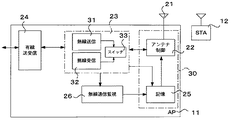
図2は、図1におけるアクセスポイント11の詳細構成を示す図である。アクセスポイント11は、アンテナ21、アンテナ制御部22、無線送受信部23、有線送受信部24、記憶部25および無線通信監視部26を備えている。
【0011】
アンテナ21は、アダプティブアレーアンテナによって構成され(図3で後述する)、指向性を自在に変更可能である。アンテナ制御部22は、アンテナ21による指向性を制御する。無線送受信部23は、無線送信部31、無線受信部32およびスイッチ33を備え、無線送信と無線受信とを切替えながら行う。有線送受信部24は、上位装置との間で送受信を行うとともに、他方の無線基地局(以下、他局と称する)との間で送受信を行う。記憶部25は、ステーション12を識別するための識別子を記憶するとともに、各ステーション12の方位に指向性を有するビームパターンを識別子に対応付けて記憶する。識別子は、例えば、各ステーション12のMAC(Media Access Control)アドレス、又は、各ステーション12毎に固有に付与される接続ID(Identifier)である。無線通信監視部26は、無線送受信部23による通信量を監視する。
【0012】
なお、図2のアンテナ制御部22および記憶部25は、本発明の通信担当エリア決定部30を構成している。
【0013】
図3は、図2におけるアンテナ21の詳細構成を示す図である。アンテナ21は、複数のパッチアンテナ(アンテナエレメント)111,112,…,11n,121,122,…,1n1,1nnをアレー状に並べて構成されたものである。同一の信号を異なるタイミングで各パッチアンテナから送信することによって、3次元の特定方向に指向性を有するビームパターンによる送信が可能となる。また、逆に、各パッチアンテナで受信した信号を異なるタイミングで合成することによって、3次元の特定方向に指向性を有するビームパターンの受信が可能となる。あるいは、指向性の無い広角のビームパターンをつくることも可能である。
【0014】
図4は、図2におけるアンテナ制御部22の詳細構成を示す図である。アンテナ制御部22は、パッチアンテナに対応した複数の乗算部36および合成分配部37を備えている。乗算部36は、パッチアンテナで受信した信号、或いは、合成分配部37にて分配された信号に対し、記憶部25の記憶内容に従って、時間成分を含む係数を乗算する。合成分配部37は、乗算部36からの全ての信号を合成するとともに、無線送受信部23からの信号をパッチアンテナ毎に分配する。このように、アンテナ制御部22は、各パッチアンテナに対応した係数を、記憶部25の記憶内容に従って制御しており、これによって、ビームパターンの指向性を制御することができる。
【0015】
図5は、図2における記憶部25の記憶内容を示す図である。記憶部25の記憶内容として、ステーション12毎のMACアドレス#1〜#n、およびこれに対応付けられたビーム形成パターン#1〜#nをテーブル状に並べたものを、図5に表示している。アンテナ制御部22は、アクセスポイント11の通信相手(ステーション12)に応じたビーム形成パターンを、記憶部25から読み出す。ビーム形成パターンは、すなわち、乗算部36にて乗算されるパッチアンテナ毎の係数を並べたものである。これにより、通信相手となるステーション12に応じてアンテナ21の指向性を制御することができる。
【0016】
また、図5に示すように、記憶部25には、通信担当エリアに広がる広角ビーム形成パターン(ビーコン)も2種類記憶している。通信担当エリアを図1で説明すると、無線基地局11aの通信担当エリアは、無線通信エリア17a(最大のエリア)およびエリア19a(最小のエリア)のいずれかである。同様に、無線基地局11bの通信担当エリアは、無線通信エリア17b(最大のエリア)およびエリア19b(最小のエリア)のいずれかである。図5に示すように、記憶部25には、最大の通信担当エリアに対応した広角ビーム形成パターン#1、および最小の通信担当エリアに対応した広角ビーム形成パターン#2が記憶されている。
【0017】
図6は、制御信号を送信する場合のビームスポットを示す図である。図6では、アクセスポイント11aの通信担当エリアが最小のエリア19a(図2)であり、アクセスポイント11bの通信担当エリアが最大のエリア17b(図2)である場合のビームスポットを例示している。無線通信監視部26が監視する通信量により、通信担当エリアが決定される。通信担当エリアが決定されると、アンテナ制御部22は、記憶部25から図5に示したような広角ビーム形成パターンを読み出す。図6の例では、アクセスポイント11aにおいて最小の通信担当エリアに対応した広角ビーム形成パターン#2が読み出され、アクセスポイント11bにおいて最大の通信担当エリアに対応した広角ビーム形成パターン#1が読み出される。読み出されたビーム形成パターンを用いて、アクセスポイント11からステーション12に向けて、制御信号が送信される。
【0018】
このように、アクセスポイント11aが混雑して、その通信量(トラフィック)が多くなってきた場合、アクセスポイント11aのサービスエリアのうち、重複エリア18を他局(アクセスポイント11b)に譲り、アクセスポイント11aに同時に接続される加入者の数を減らし、その混雑を緩和できる。
【0019】
また、このように制御信号を送信する場合以外にも、ステーション12から送られてくる上りのデータ信号を受信する場合も、同様に、広角ビーム形成パターンを使用する。これにより、通信担当エリア内の全てのステーション12から送られてくる上りデータ信号を受信することができる。
【0020】
さらに、アクセスポイント11aとアクセスポイント11bとは、相互間でアクセスポイント間制御信号を送受して、相互の通信トラフィックを確認し合っており、他局の通信トラフィックが少ないことを確認した後に、重複エリア18を他局に譲る制御を行う。
【0021】
図7は、データ信号を送受信する場合のビームスポットを示す図である。制御信号が、図6で前述したような広角ビームスポットで送信されると、受信を待機しているステーション12は、制御信号に同期して動作し、データ信号の受信を行う。このとき、アクセスポイント11は、あるステーション12の方位に指向性を有するビームパターンを使って、データ送信を行う。したがって、図7に示すように、データ信号の送信を行う場合、アクセスポイント11によるビームスポットは、ステーション12を含んだ限定的なエリア40に絞られる。
【0022】
このように、ビームスポットを絞ることにより、干渉を少なくするとともに、大容量のデータ信号を伝送することが可能である。
【0023】
一方、ステーション12のアンテナは、図示しないが、アクセスポイント11a,11bの方位に指向性を有するものであり、例えば、パラボラアンテナ又は平面アンテナである。ステーション12が固定されていること、及びその通信相手がアクセスポイント11a,11bのみであることから、指向性が固定されたパラボラアンテナがステーション12のアンテナとして適している。
【0024】
次に、固定無線アクセスシステムの動作を説明する。
【0025】
まず、アクセスポイント11は、その通信担当エリア全体に広がる広角なビームパターンを用いて、ステーション12に制御信号を送信する。この制御信号は、アクセスポイント11毎に定められた周波数の搬送波を用いて、一定周期ごとに送信される。ステーション12では、アクセスポイント11からの制御信号を受信し、その受信電界強度の大きい方の制御信号に同期して動作する。続いて、データ信号の受信を待機するステーション12は、同期したアクセスポイント11にアクセス要求信号を送信する。
【0026】
ステーション12から送信されたアクセス要求信号は、ステーション12の識別子を含んでおり、アクセスポイント11の無線受信部32によって受信される。アクセス要求信号の識別子は、記憶部25に登録されている識別子と照合される。未登録の場合は、初めてのアクセスであると判断し、アンテナ制御部22は、アンテナ21を制御して通信担当エリア内を指向性を順次変えてサーチする。このサーチによって、受信電界強度が最大となるビームパターンを探し出し、探し出されたビームパターンを使ってデータ信号の送受信を行うとともに、記憶部25にこのビームパターンを記憶する。既に登録済みの場合、アンテナ制御部22は、アンテナ21を過去の設定値(記憶部25に記憶されたビームパターン)に従って制御し、ステーション12の方位に指向性を絞って、データ信号の送信を行う。
【0027】
図8は、制御信号およびデータ信号の伝送タイミングを示す図である。図8の上段は、アクセスポイント11aに関する伝送タイミングを、図8の下段は、アクセスポイント11bに関する伝送タイミングを示している。ここで、アクセスポイント11aは周波数f1を用い、アクセスポイント11bは周波数f2(周波数f1とは異なる周波数)を用いるように割り当てられているものとする。
【0028】
アクセスポイント11aは、通信担当エリアに広がる広角ビームパターンを用いて、制御信号41を送信し、広角ビームパターンのまま上りデータ信号43を受信する。続いて、アクセスポイント11aは、ステーション12の方位に指向性を絞ったビームパターンを用いて、下りデータ信号45を送信する。
【0029】
一方のアクセスポイント11bは、通信担当エリアに広がる広角ビームパターンを用いて、制御信号42を送信し、ステーション12の方位に指向性を絞ったビームパターンを用いて、下りデータ信号46を送信する。続いて、アクセスポイント11bは、ビームパターンを広角のものに戻して、上りデータ信号43を受信する。
【0030】
このようにすることで、多値変調等の大きなC/N(Carrier/Noise)比を必要とする通信においても、アンテナゲインを上げることができることから、EIRP(Effective Isotropic Radiated Power)も上がり、それぞれのステーション12の受信端においても、C/N比が上がり、高速な通信レートを確保できる。また、指向性を絞ることから、集合住宅16のサービスエリア外の地域に不要な輻射が広がってしまう確率も下がり、周囲の電波干渉も低減できる。
【0031】
図9は、担当のアクセスポイントを変更する場合の信号伝送タイミングを例示する図である。図9の上段は、アクセスポイント11aに関する伝送タイミングを、図9の下段は、アクセスポイント11bに関する伝送タイミングを示している。また、図9では、横軸が時間を、縦軸が電解強度を示している。
【0032】
まず、アクセスポイント11aが制御信号51を送信し、アクセスポイント11bが制御信号52を送信する。ステーション12は、これらの制御信号51,52を受信し、それぞれの受信電界強度を比較して、電界強度の大きい方のアクセスポイント11aと通信を行う。すなわち、アクセスポイント11aは、ステーション12からの上りデータ信号53を受信した後、下りデータ信号54をステーション12に送信する。
【0033】
次に、アクセスポイント11aのトラフィックが上昇し、その通信担当エリアをエリア17aからエリア19aに(図2)変更する。このとき、アクセスポイント11aが制御信号51を送信し、アクセスポイント11bが制御信号52を送信するが、それぞれの電界強度は、制御信号51よりも制御信号52の方が大きくなっている。ステーション12は、周波数を変更し、制御信号52の受信電界強度が制御信号51の受信電界強度よりも大きいことを確認し、通信担当エリアに変更があったことを認識する。
【0034】
次に、ステーション12は、アクセスポイント11bにアクセス要求信号55を送信する。アクセス要求信号55を受信したアクセスポイント11bは、ステーション12にアクセス許可信号56を返す。このとき、アクセスポイント11aとアクセスポイント11bとは、アクセスポイント間制御信号を介して、ステーション12がアクセスポイント11aからアクセスポイント11bの配下に変わったことを伝え合う。
【0035】
次に、アクセスポイント11aが制御信号51を送信し、アクセスポイント11bが制御信号52を送信する。ステーション12は、これらの制御信号51,52を受信し、それぞれの受信電界強度を比較して、電界強度の大きい方のアクセスポイント11bと通信を行う。すなわち、アクセスポイント11bは、ステーション12からの上りデータ信号53を受信した後、下りデータ信号54をステーション12に送信する。
【0036】
このようにすることで、アクセスポイント11aの通信トラフィックを緩和することができ、良好な通信品質を確保できる。
【0037】
また、アクセスポイント11a及びアクセスポイント11b及びステーション12は、それぞれハンドオーバー機能を有している。例えば、アクセスポイント11aとステーション12とが通信している途中に、通信担当エリアの変更があってステーション12がアクセスポイント11aの通信担当エリアから外れ、アクセスポイント11bの通信担当エリアに含まれるようになった場合においても、アクセスポイント間制御信号により、アクセスポイント11aからアクセスポイント11bへ通信継続を通知し、上りデータ信号53および下りデータ信号54の伝送を継続しながら、アクセス要求信号55およびアクセス許可信号56を交換し合う。
【0038】
このように、ステーション12から見た通信相手として、アクセスポイント11aからアクセスポイント11bへの切替えを、通信を途切れさせることなく実行することができる。
【0039】
実施の形態2.
実施の形態2は、前述した実施の形態1の一部を変更したものである。すなわち、実施の形態1は、図2の無線通信監視部26において無線送受信部23の通信量を監視するものであったが、実施の形態2は、無線通信監視部26において無線送受信部23の通信品質を監視するものである。これ以外の点では、実施の形態2は、実施の形態1と同様の構成を成し、同様に動作するため、説明を省略する。
【0040】
図10は、本発明の実施の形態2に係る固定無線アクセスシステムを示す図である。無線通信監視部26では、上記のように、無線送受信部23の通信品質を監視している。例えば、ステーション12から送られてくる無線信号のSIR(信号対干渉比)を検出し、検出値を所定の閾値と比較しており、検出値が所定の閾値より小さくなった場合、干渉波を受信しているものと判断する。
【0041】
ここで、図10に示すように、集合住宅16と無関係の地点で干渉波60が発生し、アクセスポイント11から見て重複エリア18の方位から干渉波60が到来したとする。また、干渉波60の周波数は、アクセスポイント11aの動作周波数と同一であるものとする。この場合、アクセスポイント11aでは、干渉波が発生したと判断して、重複エリア18をアクセスポイント11bに譲り、アクセスポイント11bにて重複エリア18に設置されたステーション12との通信を継続する。
【0042】
このように、重複エリア18をアクセスポイント11bに譲るため、アクセスポイント11aから見て、干渉波60の到来方向にはヌル点が形成されるため、干渉波60の受信を回避できる。特に、電波利用に規制のない周波数帯を用いるIEEE802.11bに準拠する場合でも、干渉波の受信を回避することが可能となる。
【0043】
【発明の効果】
以上説明したように、本発明によれば、固定無線アクセスシステムにおいて通信量に応じて通信担当エリアを変更することによって、一方の無線基地局にアクセスが集中した場合でも、重複エリアを他方の無線基地局に担当させることができ、全体として無線基地局の利用効率を向上できる。
【0044】
あるいは、本発明によれば、固定無線アクセスシステムにおいて通信品質に応じて通信担当エリアを変更することによって、一方の無線基地局に干渉が発生する等して通信品質が劣化した場合でも、重複エリアを他方の無線基地局に担当させて、通信品質の劣化を防止できる。
【図面の簡単な説明】
【図1】本発明の実施の形態に係る固定無線アクセスシステムの全体構成を示す図である。
【図2】図1におけるアクセスポイント11の詳細構成を示す図である。
【図3】図2におけるアンテナ21の詳細構成を示す図である。
【図4】図2におけるアンテナ制御部22の詳細構成を示す図である。
【図5】図2における記憶部25の記憶内容を示す図である。
【図6】制御信号を送信する場合のビームスポットを示す図である。
【図7】データ信号を送受信する場合のビームスポットを示す図である。
【図8】制御信号およびデータ信号の伝送タイミングを示す図である。
【図9】担当のアクセスポイントを変更する場合の信号伝送タイミングを例示する図である。
【図10】本発明の実施の形態2に係る固定無線アクセスシステムを示す図である。
【符号の説明】
11a,11b アクセスポイント(無線基地局)
12 ステーション(固定無線端末)
16 集合住宅
17a,17b 無線通信エリア(最大の通信担当エリア)
18 重複エリア
19a,19b エリア(最小の通信担当エリア)
21 アンテナ
22 アンテナ制御部
23 無線送受信部
24 有線送受信部
25 記憶部
26 無線通信監視部
30 通信担当エリア決定部
31 無線送信部
32 無線受信部
33 スイッチ
36 乗算部
37 合成分配部
38 記憶装置
40 エリア
41,42,51,52 制御信号
43,44,53 上りデータ信号
45,46,54 下りデータ信号
55 アクセス要求信号
56 アクセス許可信号
60 干渉波[0001]
TECHNICAL FIELD OF THE INVENTION
The present invention relates to a fixed wireless access system including a wireless base station and a plurality of fixed wireless terminals installed in the wireless communication area.
[0002]
[Prior art]
As a conventional technique, for example, there is a wireless LAN (Local Area Network) system as described in Patent Document 1 below. In this wireless LAN system, an access point (wireless base station) manages mobile stations (wireless terminals) within its service area (wireless communication area), and a predetermined number of wireless terminals are sent from the wireless base station to the wireless terminals. If a connection request is made beyond that, the wireless base station limits the connection of the wireless terminal.
[0003]
[Patent Document 1] JP-A-11-055286 [Patent Document 2] JP-A-09-064876 [Patent Document 3] JP-A-08-256162 [Problems to be Solved by the Invention]
However, in the conventional technology, when a connection request is made from a limited number of wireless terminals to a specific wireless base station, even if an idle channel remains in an adjacent wireless base station, some wireless The terminal cannot be connected to the line, and the use efficiency of the wireless base station is reduced.
[0004]
In particular, in a fixed wireless access system using a fixed station (fixed wireless terminal) instead of a mobile station, the wireless terminals are fixedly arranged at predetermined positions, and the number of fixed wireless terminals to be connected is grasped by the wireless base station. Despite the ease of operation, the use efficiency of the wireless base station is reduced as in a wireless LAN system using a mobile station.
[0005]
SUMMARY OF THE INVENTION An object of the present invention is to provide a fixed wireless access system capable of improving the utilization efficiency of a wireless base station and efficiently connecting a fixed wireless terminal to a line.
[0006]
[Means for Solving the Problems]
The present invention includes first and second wireless base stations whose wireless communication areas partially overlap with each other, and a plurality of fixed wireless terminals installed in the wireless communication areas of the first and second wireless base stations. A fixed wireless access system, wherein the first and second wireless base stations perform wireless communication with the fixed wireless terminal, and wirelessly monitor communication volume or communication quality of the wireless transceiver. A fixed wireless access system comprising: a communication monitoring unit; and a communication area determining unit that determines a communication area according to the communication volume or the communication quality.
[0007]
BEST MODE FOR CARRYING OUT THE INVENTION
Embodiment 1 FIG.
FIG. 1 is a diagram showing an entire configuration of a fixed wireless access system according to an embodiment of the present invention. This fixed wireless access system is a wireless LAN system including access points (APs) 11a and 11b and a plurality of stations (STAs) 12, and FIG. 1 illustrates an example applied to an apartment house. Hereinafter, the access points 11a and 11b may be referred to as the access point 11 depending on the content.
[0008]
The access point 11 corresponds to the wireless base station of the present invention, and is installed at a position facing the apartment house 16, for example, fixed to a telephone pole. The station 12 corresponds to the fixed wireless terminal of the present invention, and is fixedly installed in each room of the apartment house 16. All stations 12 installed in the apartment house 16 are included in any of the wireless communication areas 17a and 17b corresponding to the access points 11a and 11b, respectively. The wireless communication areas 17a and 17b are areas where the access points 11a and 11b can communicate with each other, and form an overlapping area 18 that overlaps with each other. The area 19a is an area obtained by removing the overlapping area 18 from the wireless communication area 17a. Similarly, the area 19b is an area obtained by removing the overlapping area 18 from the wireless communication area 17b.
[0009]
As described above, the station 12 can communicate with at least one of the access points 11a and 11b, and among them, the station 12 located in the overlapping area 18 can communicate with both the access points 11a and 11b.
[0010]
FIG. 2 is a diagram showing a detailed configuration of the access point 11 in FIG. The access point 11 includes an antenna 21, an antenna control unit 22, a wireless transmitting / receiving unit 23, a wired transmitting / receiving unit 24, a storage unit 25, and a wireless communication monitoring unit 26.
[0011]
The antenna 21 is configured by an adaptive array antenna (described later with reference to FIG. 3), and can change the directivity freely. The antenna control unit 22 controls the directivity of the antenna 21. The wireless transmission / reception unit 23 includes a wireless transmission unit 31, a wireless reception unit 32, and a switch 33, and performs switching between wireless transmission and wireless reception. The wired transmission / reception unit 24 performs transmission and reception with a higher-level device, and also performs transmission and reception with the other wireless base station (hereinafter, referred to as another station). The storage unit 25 stores an identifier for identifying the station 12 and stores a beam pattern having directivity in the direction of each station 12 in association with the identifier. The identifier is, for example, a MAC (Media Access Control) address of each station 12 or a connection ID (Identifier) uniquely assigned to each station 12. The wireless communication monitoring unit 26 monitors the amount of communication by the wireless transmitting / receiving unit 23.
[0012]
In addition, the antenna control unit 22 and the storage unit 25 of FIG. 2 constitute a communication area determination unit 30 of the present invention.
[0013]
FIG. 3 is a diagram showing a detailed configuration of the antenna 21 in FIG. The antenna 21 is configured by arranging a plurality of patch antennas (antenna elements) 111, 112,..., 11n, 121, 122,. By transmitting the same signal from each patch antenna at different timings, it is possible to transmit by a beam pattern having directivity in a specific three-dimensional direction. Conversely, by combining the signals received by the patch antennas at different timings, it becomes possible to receive a beam pattern having directivity in a specific three-dimensional direction. Alternatively, a wide-angle beam pattern without directivity can be created.
[0014]
FIG. 4 is a diagram showing a detailed configuration of the antenna control unit 22 in FIG. The antenna control unit 22 includes a plurality of multiplication units 36 and a synthesis distribution unit 37 corresponding to the patch antenna. The multiplying unit 36 multiplies the signal received by the patch antenna or the signal distributed by the combining and distributing unit 37 by a coefficient including a time component according to the storage content of the storage unit 25. The combining and distributing unit 37 combines all the signals from the multiplying unit 36 and distributes the signal from the wireless transmitting and receiving unit 23 for each patch antenna. As described above, the antenna control unit 22 controls the coefficient corresponding to each patch antenna according to the storage content of the storage unit 25, and thereby can control the directivity of the beam pattern.
[0015]
FIG. 5 is a diagram showing the contents stored in the storage unit 25 in FIG. As the contents stored in the storage unit 25, the MAC addresses # 1 to #n for each station 12 and the beam forming patterns # 1 to #n associated with the MAC addresses are arranged in a table and displayed in FIG. I have. The antenna control unit 22 reads from the storage unit 25 a beam forming pattern corresponding to the communication partner (station 12) of the access point 11. In other words, the beam forming pattern is obtained by arranging coefficients for each patch antenna to be multiplied by the multiplier 36. Thereby, the directivity of the antenna 21 can be controlled according to the station 12 that is the communication partner.
[0016]
As shown in FIG. 5, the storage unit 25 also stores two types of wide-angle beam forming patterns (beacons) that spread over the communication area. Explaining the communication area in FIG. 1, the communication area of the wireless base station 11a is one of the wireless communication area 17a (the largest area) and the area 19a (the smallest area). Similarly, the communication area of the wireless base station 11b is one of the wireless communication area 17b (the largest area) and the area 19b (the smallest area). As shown in FIG. 5, the storage unit 25 stores a wide-angle beam forming pattern # 1 corresponding to the largest communication area and a wide-angle beam forming pattern # 2 corresponding to the smallest communication area.
[0017]
FIG. 6 is a diagram illustrating a beam spot when a control signal is transmitted. FIG. 6 illustrates a beam spot when the communication area of the access point 11a is the smallest area 19a (FIG. 2) and the communication area of the access point 11b is the largest area 17b (FIG. 2). . The area in charge of communication is determined based on the amount of communication monitored by the wireless communication monitoring unit 26. When the communication area is determined, the antenna control unit 22 reads a wide-angle beam forming pattern as shown in FIG. In the example of FIG. 6, the wide-angle beam forming pattern # 2 corresponding to the smallest communication area is read at the access point 11a, and the wide-angle beam forming pattern # 1 corresponding to the largest communication area is read at the access point 11b. . A control signal is transmitted from the access point 11 to the station 12 using the read beamforming pattern.
[0018]
As described above, when the access point 11a becomes congested and the traffic (traffic) increases, the overlapping area 18 of the service area of the access point 11a is transferred to another station (access point 11b), and the access point 11a is accessed. 11a, the number of subscribers connected simultaneously can be reduced, and congestion can be reduced.
[0019]
In addition to the case where the control signal is transmitted as described above, the case where the upstream data signal transmitted from the station 12 is received also uses the wide-angle beam forming pattern. Thereby, it is possible to receive the uplink data signals transmitted from all the stations 12 in the communication area.
[0020]
Furthermore, the access point 11a and the access point 11b transmit and receive a control signal between access points to mutually confirm communication traffic between them. After confirming that communication traffic of other stations is small, the access point 11a and the access point 11b Control is performed to transfer the area 18 to another station.
[0021]
FIG. 7 is a diagram showing beam spots when transmitting and receiving data signals. When the control signal is transmitted by the wide-angle beam spot as described above with reference to FIG. 6, the station 12 waiting for reception operates in synchronization with the control signal and receives the data signal. At this time, the access point 11 performs data transmission using a beam pattern having directivity in the direction of a certain station 12. Therefore, as shown in FIG. 7, when transmitting a data signal, the beam spot by the access point 11 is narrowed down to a limited area 40 including the station 12.
[0022]
Thus, by narrowing the beam spot, it is possible to reduce interference and transmit a large-capacity data signal.
[0023]
On the other hand, although not shown, the antenna of the station 12 has directivity in the directions of the access points 11a and 11b, and is, for example, a parabolic antenna or a planar antenna. Since the station 12 is fixed and its communication partner is only the access points 11a and 11b, a parabolic antenna with fixed directivity is suitable as the antenna of the station 12.
[0024]
Next, the operation of the fixed wireless access system will be described.
[0025]
First, the access point 11 transmits a control signal to the station 12 using a wide-angle beam pattern spread over the entire communication area. This control signal is transmitted at regular intervals using a carrier having a frequency determined for each access point 11. The station 12 receives the control signal from the access point 11 and operates in synchronization with the control signal having the larger received electric field strength. Subsequently, the station 12 waiting to receive the data signal transmits an access request signal to the synchronized access point 11.
[0026]
The access request signal transmitted from the station 12 includes the identifier of the station 12 and is received by the wireless reception unit 32 of the access point 11. The identifier of the access request signal is collated with the identifier registered in the storage unit 25. If not registered, it is determined that the access is the first access, and the antenna control unit 22 controls the antenna 21 to search the communication area in order by changing the directivity sequentially. By this search, a beam pattern having the maximum received electric field strength is searched for, a data signal is transmitted / received using the found beam pattern, and this beam pattern is stored in the storage unit 25. If it has already been registered, the antenna control unit 22 controls the antenna 21 according to the past set value (the beam pattern stored in the storage unit 25), narrows the directivity to the azimuth of the station 12, and transmits the data signal. Do.
[0027]
FIG. 8 is a diagram illustrating transmission timings of a control signal and a data signal. The upper part of FIG. 8 shows the transmission timing for the access point 11a, and the lower part of FIG. 8 shows the transmission timing for the access point 11b. Here, it is assumed that the access point 11a is assigned to use the frequency f1, and the access point 11b is assigned to use the frequency f2 (a frequency different from the frequency f1).
[0028]
The access point 11a transmits the control signal 41 using the wide-angle beam pattern spread over the communication area, and receives the uplink data signal 43 with the wide-angle beam pattern. Subsequently, the access point 11a transmits the downlink data signal 45 using a beam pattern whose directivity is narrowed down to the azimuth of the station 12.
[0029]
One access point 11b transmits the control signal 42 using a wide-angle beam pattern spread over the communication area, and transmits the downlink data signal 46 using a beam pattern whose directivity is narrowed down in the direction of the station 12. Subsequently, the access point 11b returns the beam pattern to the wide-angle beam pattern and receives the uplink data signal 43.
[0030]
By doing so, the antenna gain can be increased even in communication requiring a large C / N (Carrier / Noise) ratio such as multi-level modulation, so that EIRP (Effective Isotropic Radiated Power) also increases, and Also at the receiving end of the station 12, the C / N ratio increases, and a high communication rate can be secured. Further, since the directivity is narrowed, the probability that unnecessary radiation spreads to an area outside the service area of the apartment house 16 is reduced, and surrounding radio wave interference can be reduced.
[0031]
FIG. 9 is a diagram illustrating a signal transmission timing when the assigned access point is changed. The upper part of FIG. 9 shows the transmission timing for the access point 11a, and the lower part of FIG. 9 shows the transmission timing for the access point 11b. In FIG. 9, the horizontal axis represents time, and the vertical axis represents electrolytic strength.
[0032]
First, the access point 11a transmits a control signal 51, and the access point 11b transmits a control signal 52. The station 12 receives these control signals 51 and 52, compares the respective received electric field strengths, and communicates with the access point 11a having the larger electric field strength. That is, after receiving the uplink data signal 53 from the station 12, the access point 11a transmits the downlink data signal 54 to the station 12.
[0033]
Next, the traffic of the access point 11a rises, and its communication area is changed from the area 17a to the area 19a (FIG. 2). At this time, the access point 11a transmits the control signal 51 and the access point 11b transmits the control signal 52, and the electric field strength of the control signal 52 is higher than that of the control signal 51. The station 12 changes the frequency, confirms that the received electric field strength of the control signal 52 is larger than the received electric field strength of the control signal 51, and recognizes that the communication area has been changed.
[0034]
Next, the station 12 transmits an access request signal 55 to the access point 11b. The access point 11b that has received the access request signal 55 returns an access permission signal 56 to the station 12. At this time, the access point 11a and the access point 11b communicate via the inter-access point control signal that the station 12 has been changed from the access point 11a to the subordinate of the access point 11b.
[0035]
Next, the access point 11a transmits the control signal 51, and the access point 11b transmits the control signal 52. The station 12 receives these control signals 51 and 52, compares the respective received electric field strengths, and communicates with the access point 11b having the larger electric field strength. That is, after receiving the uplink data signal 53 from the station 12, the access point 11b transmits the downlink data signal 54 to the station 12.
[0036]
By doing so, communication traffic of the access point 11a can be reduced, and good communication quality can be ensured.
[0037]
Further, the access point 11a, the access point 11b, and the station 12 each have a handover function. For example, during the communication between the access point 11a and the station 12, the communication area is changed so that the station 12 deviates from the communication area of the access point 11a and is included in the communication area of the access point 11b. In this case, the access point 11a notifies the access point 11b of the continuation of the communication by the inter-access point control signal, and the access request signal 55 and the access permission signal are transmitted while the transmission of the uplink data signal 53 and the downlink data signal 54 is continued. The signals 56 are exchanged.
[0038]
As described above, switching from the access point 11a to the access point 11b as a communication partner viewed from the station 12 can be executed without interrupting communication.
[0039]
Embodiment 2 FIG.
The second embodiment is a modification of the first embodiment. That is, in the first embodiment, the wireless communication monitoring unit 26 of FIG. 2 monitors the traffic of the wireless transmitting / receiving unit 23, but in the second embodiment, It monitors communication quality. In other respects, the second embodiment has the same configuration as the first embodiment and operates in the same manner, so that the description will be omitted.
[0040]
FIG. 10 is a diagram showing a fixed wireless access system according to Embodiment 2 of the present invention. The wireless communication monitoring unit 26 monitors the communication quality of the wireless transmitting and receiving unit 23 as described above. For example, the SIR (Signal-to-Interference Ratio) of the radio signal transmitted from the station 12 is detected, and the detected value is compared with a predetermined threshold. If the detected value is smaller than the predetermined threshold, the interference wave is detected. Judge as receiving.
[0041]
Here, as shown in FIG. 10, it is assumed that an interference wave 60 is generated at a point unrelated to the apartment house 16 and arrives from the direction of the overlapping area 18 when viewed from the access point 11. The frequency of the interference wave 60 is the same as the operating frequency of the access point 11a. In this case, the access point 11a determines that an interference wave has occurred, transfers the overlapping area 18 to the access point 11b, and continues communication with the station 12 installed in the overlapping area 18 at the access point 11b.
[0042]
As described above, since the overlapping area 18 is yielded to the access point 11b, a null point is formed in the arrival direction of the interference wave 60 when viewed from the access point 11a, so that the reception of the interference wave 60 can be avoided. In particular, even in the case of complying with IEEE802.11b using a frequency band in which use of radio waves is not restricted, reception of an interference wave can be avoided.
[0043]
【The invention's effect】
As described above, according to the present invention, by changing the communication area in accordance with the traffic in the fixed wireless access system, even when access is concentrated on one wireless base station, the overlapping area can be changed to the other wireless base station. The base station can be in charge, and the use efficiency of the wireless base station can be improved as a whole.
[0044]
Alternatively, according to the present invention, by changing the communication area in accordance with the communication quality in the fixed wireless access system, even if the communication quality is degraded due to, for example, interference occurring in one radio base station, the overlapping area Is assigned to the other radio base station to prevent deterioration of communication quality.
[Brief description of the drawings]
FIG. 1 is a diagram showing an entire configuration of a fixed wireless access system according to an embodiment of the present invention.
FIG. 2 is a diagram showing a detailed configuration of an access point 11 in FIG.
FIG. 3 is a diagram showing a detailed configuration of an antenna 21 in FIG. 2;
4 is a diagram showing a detailed configuration of an antenna control unit 22 in FIG.
FIG. 5 is a diagram showing the contents stored in a storage unit 25 in FIG. 2;
FIG. 6 is a diagram illustrating a beam spot when a control signal is transmitted.
FIG. 7 is a diagram showing beam spots when transmitting and receiving data signals.
FIG. 8 is a diagram illustrating transmission timings of a control signal and a data signal.
FIG. 9 is a diagram illustrating a signal transmission timing when an assigned access point is changed;
FIG. 10 is a diagram showing a fixed wireless access system according to Embodiment 2 of the present invention.
[Explanation of symbols]
11a, 11b Access point (wireless base station)
12 stations (fixed wireless terminal)
16 Apartment 17a, 17b Wireless communication area (largest communication area)
18 Overlap area 19a, 19b area (minimum communication area)
21 antenna 22 antenna control unit 23 wireless transmission / reception unit 24 wired transmission / reception unit 25 storage unit 26 wireless communication monitoring unit 30 communication area determination unit 31 wireless transmission unit 32 wireless reception unit 33 switch 36 multiplication unit 37 synthesis distribution unit 38 storage device 40 area 41, 42, 51, 52 control signals 43, 44, 53 uplink data signals 45, 46, 54 downlink data signals 55 access request signals 56 access permission signals 60 interference waves