JP2004234598A - Gas concentration monitoring system - Google Patents
Gas concentration monitoring system Download PDFInfo
- Publication number
- JP2004234598A JP2004234598A JP2003025629A JP2003025629A JP2004234598A JP 2004234598 A JP2004234598 A JP 2004234598A JP 2003025629 A JP2003025629 A JP 2003025629A JP 2003025629 A JP2003025629 A JP 2003025629A JP 2004234598 A JP2004234598 A JP 2004234598A
- Authority
- JP
- Japan
- Prior art keywords
- gas
- signal
- gas concentration
- sensor
- information storage
- Prior art date
- Legal status (The legal status is an assumption and is not a legal conclusion. Google has not performed a legal analysis and makes no representation as to the accuracy of the status listed.)
- Pending
Links
Images
Abstract
Description
【0001】
【発明の属する技術分野】
本発明は、デバイスネットに適したガス濃度監視システム、より詳細にはガス検出ユニットからのデータを中央監視装置に伝送するための方式に関する。
【0002】
【従来の技術】
ガス濃度監視システムの分野では、ステータス信号に8ビット、また濃度信号に8ビットを割り当て、合計16ビットの信号をパラレルで伝送する方式が採用されている。
一方、プラント、半導体、自動車といった製造業の分野では、制御信号や機器設定用のデータのやりとりをシリアル通信で行う、標準化されたネットワーク、いわゆるデバイスネット(登録商標)が広く利用され、リミットスイッチ、光電センサ、バルブマニホルド、モータスタータ、プロセスセンサ、バーコードリーダ、可変周波数ドライバ、パネルディスプレイ、オペレータインタフェース等の産業デバイスの接続が可能な通信リンクが構築されている。
【0003】
【発明が解決しようとする課題】
本発明は、このような事情に鑑みなされたものであって、その目的とするところは、デバイスネットが潜在的に備えているリソースを有効に利用して中央監視装置にガス濃度信号を高い分解能で伝送できるとともに、センサー情報をも合わせて伝送できるガス濃度監視システムを提供することにある。
【0004】
【課題を解決するための手段】
このような問題を解消するために本発明においては、ガスセンサー、制御監視手段、及びセンサ情報記憶手段と、デバイスネットに準拠した信号に変換するデバイスネット用インターフェイスとを備えたガス検出ユニットと、デバイスネット用インタフェース、制御手段、表示警報手段、及び入力手段からなる中央監視装置と、を備え、前記ガスセンサにより検出されたガス濃度信号を16ビットで、また前記センサ情報記憶手段の信号及びステータス信号を16ビットで伝送するようにした。
【0005】
【作用】
センサ情報記憶手段のデータに基づいて各ガス検出ユニットのステータス信号とセンサ情報とを16ビットで伝送するとともに、ガス濃度信号をも16ビットで伝送する。
【0006】
【発明の実施の態様】
そこで以下に本発明の詳細を図示した実施例に基づいて説明する。
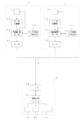
図1は、本発明の一実施例を示すものであって、各種装置の近傍に配置されるガス検出ユニット1は、電気化学式ガスセンサや半導体ガスセンサ、熱線式ガスセンサ等からなるセンサ10と、アナログーデジタル変換器11、マイクロコンピュータにより構成された監視制御手段12、アナログーデイジタル変換器11と監視制御手段12からのステータス信号をデバイスネットに準拠した信号に変換するデバイスネット用インターフェイス13、及び、センサ情報記憶手段14とにより構成されている。
【0007】
センサ情報記憶手段14は、それぞれのガス検出ユニット1に設定されている濃度単位コード(vol%、%LEL、ppm、ppb)、小数点コード(1/1、1/10、1/100、1/1000)、第1警報点の濃度、第2警報点の濃度、サプレス値、及び警報遅延時間のデータ等を不揮発性メモリに格納して構成されている。
【0008】
各ガス検出ユニット1は、インターフェイス13を介してデバイスネット標準ケーブル2により中央監視装置3に接続されている。中央監視装置3は、デバイスネット用インタフェース30、制御手段31、デイスプレイ32、警報器33、入力手段34により構成され、ガス検出ユニット1からのガス濃度信号やステータス信号を受け、制御手段31によりガスの濃度をデイスプレイ32に表示したり、ガスの濃度が基準値を超えた場合に警報器33を作動させ、また入力手段34の指令によりガス検出ユニット1からセンサ情報を伝送させる。
【0009】
ガス濃度信号とステータス信号とは、切換えによりそれぞれ1ブロックとして伝送されていて、本発明においては表1に示したように、デバイスネットの信号幅である16ビットに拡張されている。
これにより、表1に示したようにガス濃度信号を符号付きの15ビットのデータとして、またステータス信号を16ビットにより伝送することができ、高い分解精度のガス濃度信号と、詳細なステータスの伝送が可能となる。
【0010】
【表1】

各ガス検出ユニット1は、通常のガス監視状態では、ガス濃度信号を構成する16ビットと、ステータス信号を構成する16ビットの、合計32ビットの信号を出力する。この32ビットの信号は、デバイスネットにより中央監視装置3に伝送される。
ところが、中央監視装置3は、32ビットで伝送されるこれらガス濃度信号、及びステータス信号の他に、センサ情報を必要とする場合がある。
しかし、デバイスネットで伝送可能な回線幅32ビットが、ガス検出ユニット1からの信号の伝送のために既に予約されているため、新たなデータであるセンサ情報をセンサユニット1側から伝送することが不可能である。
このため、本発明においては、ステータス信号の1ビット、この実施例ではステータス信号の第4ビットで4特殊コードを指定するように構成されている。
【0012】
すなわち、特殊コードは、「0」、「1」の2種類のデータの設定が可能となっていて、
通常のガス監視状態では、特殊コードが「0」に設定されていて、第0ビットと第1ビットとにより小数点の位置を、また第2ビットと第3ビットとで濃度単位を特定している。
すなわち、
第0ビット「0」、第1ビット「0」 1/1
第0ビット「0」、第1ビット「1」 1/10
第0ビット「1」、第1ビット「0」 1/100
第0ビット「1」、第1ビット「1」 1/1000
を出力する。
また第2ビットと第3ビットは、
第2ビット「0」、第3ビット「0」 vol%
第2ビット「0」、第3ビット「1」 %LEL
第2ビット「1」、第3ビット「0」 ppm
第2ビット「1」、第3ビット「1」 ppb
を出力する。
【0013】
一方、中央監視装置3の入力手段1により第4ビットの特殊コードに「1」が指定されると、第0ビット、第1ビット、第2ビット、及び第3ビットの4ビットにより16種類の別の情報、つまりセンサ情報記憶手段14に格納されている他のセンサ情報、つまり第1警報点の濃度、第2警報点の濃度、サプレス値、及び警報遅延時間等のデータを通常のガス監視状態よりも余分に伝送することが可能となる。
これにより、デバイスネットで伝送可能な情報以上の情報を伝送することができ、中央監視装置側での各ガス検出ユニット毎の設定用データの入力作業を大幅に減らすことができる。
【0014】
なお、従来の装置では、表2に示したようにステータス信号及びガス濃度信号が共に8ビットにより伝送されていたので、分解能が低く、またガスセンサーの詳細な状態を把握することが困難であった。
【0015】
【表2】
さらには中央監視装置3により定期的にガス検出ユニット1、1、‥‥を呼び出して、各ガス検出ユニット1のセンサ情報記憶手段11の適宜の情報をデバイスネット2に出力させて伝送させることにより、各ガス検出ユニット1との通信状態を検定することができる。
【0017】
【発明の効果】
以上、説明したように本発明によれば、センサ情報記憶手段のデータに基づいて各ガス検出ユニットのステータス信号とセンサ情報とを16ビットで伝送するとともに、ガス濃度信号をも伝送するため、デバイスネットの資源を有効に利用して、中央監視装置でのデータの入力作業を可及的に減少させつつ、各ガス検出ユニットの詳細な情報を表示することができる。
【図面の簡単な説明】
【図1】本発明の一実施例を示す構成図である。
【符号の説明】
1 ガス検出ユニット
2 通信ケーブル
3 中央監視装置
10 ガスセンサ
32 デイスプレイ
33 警報器
34 入力手段[0001]
TECHNICAL FIELD OF THE INVENTION
The present invention relates to a gas concentration monitoring system suitable for a device net, and more particularly, to a method for transmitting data from a gas detection unit to a central monitoring device.
[0002]
[Prior art]
In the field of the gas concentration monitoring system, a method of allocating 8 bits to the status signal and 8 bits to the concentration signal and transmitting a total of 16 bits of signal in parallel has been adopted.
On the other hand, in the fields of manufacturing industries such as plants, semiconductors, and automobiles, a standardized network, that is, a device network (registered trademark) that exchanges control signals and data for device setting by serial communication is widely used, and limit switches, Communication links that can connect industrial devices such as photoelectric sensors, valve manifolds, motor starters, process sensors, barcode readers, variable frequency drivers, panel displays, and operator interfaces have been constructed.
[0003]
[Problems to be solved by the invention]
The present invention has been made in view of such circumstances, and an object of the present invention is to effectively utilize resources provided by a device net to provide a central monitoring device with a high resolution gas concentration signal. It is an object of the present invention to provide a gas concentration monitoring system that can transmit the sensor information together with the sensor information.
[0004]
[Means for Solving the Problems]
In order to solve such a problem, in the present invention, a gas sensor, a control monitoring unit, and a sensor information storage unit, a gas detection unit including a device network interface for converting to a device network compliant signal, A central monitoring device comprising a device network interface, a control means, a display alarm means, and an input means; a 16-bit gas concentration signal detected by the gas sensor; and a signal and status signal of the sensor information storage means. Is transmitted in 16 bits.
[0005]
[Action]
The status signal and sensor information of each gas detection unit are transmitted in 16 bits based on the data in the sensor information storage means, and the gas concentration signal is also transmitted in 16 bits.
[0006]
DESCRIPTION OF THE PREFERRED EMBODIMENTS
Therefore, the details of the present invention will be described below based on the illustrated embodiment.
FIG. 1 shows an embodiment of the present invention. A
[0007]
The sensor information storage means 14 stores concentration unit codes (vol%,% LEL, ppm, ppb) and decimal point codes (1/1, 1/10, 1/100, 1 /) set in each
[0008]
Each
[0009]
The gas concentration signal and the status signal are each transmitted as one block by switching, and in the present invention, as shown in Table 1, are expanded to 16 bits which is the signal width of the device net.
As a result, as shown in Table 1, the gas concentration signal can be transmitted as signed 15-bit data and the status signal can be transmitted by 16 bits, and the gas concentration signal with high resolution accuracy and detailed status transmission can be transmitted. Becomes possible.
[0010]
[Table 1]
In the normal gas monitoring state, each
However, the central monitoring device 3 may need sensor information in addition to the gas concentration signal and the status signal transmitted in 32 bits.
However, since a line width of 32 bits that can be transmitted in the device net is already reserved for transmitting a signal from the
Therefore, in the present invention, one special bit of the status signal, in this embodiment, the fourth bit of the status signal specifies four special codes.
[0012]
That is, the special code can set two types of data, "0" and "1".
In the normal gas monitoring state, the special code is set to “0”, the position of the decimal point is specified by the 0th bit and the 1st bit, and the concentration unit is specified by the 2nd and 3rd bits. .
That is,
0th bit “0”, 1st bit “0” 1/1
0th bit “0”, 1st bit “1” 1/10
0th bit “1”, 1st bit “0” 1/100
0th bit “1”, 1st bit “1” 1/1000
Is output.
The second and third bits are
2nd bit “0”, 3rd bit “0” vol%
2nd bit “0”, 3rd bit “1”% LEL
2nd bit “1”, 3rd bit “0” ppm
2nd bit “1”, 3rd bit “1” ppb
Is output.
[0013]
On the other hand, when "1" is designated as the special code of the fourth bit by the input means 1 of the central monitoring device 3, 16 kinds of four bits of the 0th bit, the 1st bit, the 2nd bit, and the 3rd bit are provided. Other information, that is, other sensor information stored in the sensor information storage means 14, that is, data such as the density of the first alarm point, the density of the second alarm point, the suppression value, and the alarm delay time, is used for normal gas monitoring. It becomes possible to transmit more than the state.
As a result, more information than can be transmitted on the device network can be transmitted, and the work of inputting setting data for each gas detection unit on the central monitoring device side can be greatly reduced.
[0014]
In the conventional apparatus, since both the status signal and the gas concentration signal are transmitted by 8 bits as shown in Table 2, the resolution is low and it is difficult to grasp the detailed state of the gas sensor. Was.
[0015]
[Table 2]
Further, the central monitoring device 3 periodically calls the
[0017]
【The invention's effect】
As described above, according to the present invention, the status signal and the sensor information of each gas detection unit are transmitted in 16 bits based on the data of the sensor information storage means, and the gas concentration signal is also transmitted. By effectively utilizing the resources of the network, detailed information of each gas detection unit can be displayed while minimizing the data input operation at the central monitoring device.
[Brief description of the drawings]
FIG. 1 is a configuration diagram showing one embodiment of the present invention.
[Explanation of symbols]
DESCRIPTION OF
Claims (5)
デバイスネット用インタフェース、制御手段、表示警報手段、及び入力手段からなる中央監視装置と、
を備え、前記ガスセンサにより検出されたガス濃度信号を16ビットで、また前記センサ情報記憶手段の信号及びステータス信号を16ビットで伝送することを特徴とするガス濃度監視システム。A gas detection unit including a gas sensor, a control monitoring unit, and a sensor information storage unit, and a device net interface that converts the signal into a signal compliant with the device net;
A central monitoring device comprising a device network interface, control means, display alarm means, and input means;
Wherein the gas concentration signal detected by the gas sensor is transmitted in 16 bits, and the signal and status signal of the sensor information storage means are transmitted in 16 bits.
Priority Applications (1)
| Application Number | Priority Date | Filing Date | Title |
|---|---|---|---|
| JP2003025629A JP2004234598A (en) | 2003-02-03 | 2003-02-03 | Gas concentration monitoring system |
Applications Claiming Priority (1)
| Application Number | Priority Date | Filing Date | Title |
|---|---|---|---|
| JP2003025629A JP2004234598A (en) | 2003-02-03 | 2003-02-03 | Gas concentration monitoring system |
Publications (1)
| Publication Number | Publication Date |
|---|---|
| JP2004234598A true JP2004234598A (en) | 2004-08-19 |
Family
ID=32953858
Family Applications (1)
| Application Number | Title | Priority Date | Filing Date |
|---|---|---|---|
| JP2003025629A Pending JP2004234598A (en) | 2003-02-03 | 2003-02-03 | Gas concentration monitoring system |
Country Status (1)
| Country | Link |
|---|---|
| JP (1) | JP2004234598A (en) |
Cited By (2)
| Publication number | Priority date | Publication date | Assignee | Title |
|---|---|---|---|---|
| JP2009244074A (en) * | 2008-03-31 | 2009-10-22 | Riken Keiki Co Ltd | Multi-component gas detector |
| CN109459403A (en) * | 2018-12-12 | 2019-03-12 | 镇江中煤电子有限公司 | The more gas-detecting devices of underground coal mine and detection method |
-
2003
- 2003-02-03 JP JP2003025629A patent/JP2004234598A/en active Pending
Cited By (2)
| Publication number | Priority date | Publication date | Assignee | Title |
|---|---|---|---|---|
| JP2009244074A (en) * | 2008-03-31 | 2009-10-22 | Riken Keiki Co Ltd | Multi-component gas detector |
| CN109459403A (en) * | 2018-12-12 | 2019-03-12 | 镇江中煤电子有限公司 | The more gas-detecting devices of underground coal mine and detection method |
Similar Documents
| Publication | Publication Date | Title |
|---|---|---|
| CN106162528A (en) | LoRa signal and Bluetooth signal modular converter, conversion method and sender unit | |
| CN104133790B (en) | Conditional link for direct memory access controller | |
| EP2000868A1 (en) | Method of acquiring status information of I/O units | |
| JP2004234598A (en) | Gas concentration monitoring system | |
| JP2006254045A (en) | Serial bus data collecting device and data collection system | |
| JP4824449B2 (en) | Relay transmission device and centralized meter reading system | |
| KR101733817B1 (en) | Plc system for choosing between input or output contact | |
| KR20110078164A (en) | Receiver for mipi csi with multi-lane structure | |
| KR960012101B1 (en) | Serial communication control method & device using pulse transformer | |
| JPH11296444A (en) | Monitoring device | |
| JP2005051507A (en) | Communication system and address setup method therefor | |
| TW200512594A (en) | A pro-PDA field-measuring system and method | |
| KR0170740B1 (en) | Communication apparatus for programmable logic controller and data format thereof | |
| JPH086885A (en) | Control system for serial communication | |
| US7515077B2 (en) | Apparatus and method for monitoring analog peripheral devices by a processing unit | |
| JP2006273060A (en) | Information display unit for vehicle | |
| JP2778472B2 (en) | Data processing device | |
| DE50203983D1 (en) | METHOD FOR MONITORING AN AUTOMATION PLANT | |
| JPH0279536A (en) | Polling selecting device | |
| KR200308213Y1 (en) | Panel for message indication | |
| JPH0480616B2 (en) | ||
| JPH04222199A (en) | Frame format system for monitor controller | |
| KR100545649B1 (en) | A cell scheduling device and cell scheduling method | |
| JPS63206895A (en) | Centralized automatic reading system | |
| CN113759821A (en) | PLC control circuit for continuous casting ladle manipulator |
Legal Events
| Date | Code | Title | Description |
|---|---|---|---|
| A621 | Written request for application examination |
Free format text: JAPANESE INTERMEDIATE CODE: A621 Effective date: 20060112 |
|
| A131 | Notification of reasons for refusal |
Free format text: JAPANESE INTERMEDIATE CODE: A131 Effective date: 20080902 |
|
| A977 | Report on retrieval |
Free format text: JAPANESE INTERMEDIATE CODE: A971007 Effective date: 20080904 |
|
| A02 | Decision of refusal |
Free format text: JAPANESE INTERMEDIATE CODE: A02 Effective date: 20081225 |