JP2004233553A - Image forming apparatus and processing cartridge - Google Patents
Image forming apparatus and processing cartridge Download PDFInfo
- Publication number
- JP2004233553A JP2004233553A JP2003020724A JP2003020724A JP2004233553A JP 2004233553 A JP2004233553 A JP 2004233553A JP 2003020724 A JP2003020724 A JP 2003020724A JP 2003020724 A JP2003020724 A JP 2003020724A JP 2004233553 A JP2004233553 A JP 2004233553A
- Authority
- JP
- Japan
- Prior art keywords
- image
- carrier
- developer
- image forming
- toner
- Prior art date
- Legal status (The legal status is an assumption and is not a legal conclusion. Google has not performed a legal analysis and makes no representation as to the accuracy of the status listed.)
- Withdrawn
Links
Images


Abstract
Description
【0001】
【発明の属する技術分野】
本発明は、レーザービームプリンタや電子写真複写機などのカラー画像形成装置、及びこの装置本体に着脱可能なプロセスカートリッジに関するものであり、特に複数の現像装置を具備したクリーナレス系のカラー画像形成装置及びプロセスカートリッジに関するものである。
【0002】
【従来の技術】
従来、電子写真方式の複写機、レーザービームプリンタ等の画像形成装置においては、一般に感光ドラム等の像担持体を一様かつ均一に帯電する帯電プロセス、帯電後の像担持体を露光し静電潜像を書き込む露光プロセス、静電潜像にトナーを付着させてトナー像として現像する現像プロセス、像担持体上のトナー像を紙等の転写材に転写する転写プロセス、転写材上のトナー像を定着する定着プロセス、そしてトナー像転写後の像担持体表面に残った転写残トナー等の残留物を除去するクリーニングプロセス等からなる一連の画像形成プロセスによって画像を形成している。
【0003】
上述のクリーニング工程において、クリーニング装置によって回収された転写残トナーは廃棄用の容器に収められ、その後、廃棄するようにしていた。
【0004】
そのため、近年、上述のクリーニング装置を省略して画像形成装置を小型化し、かつ転写残トナーを廃棄する等のメンテナンスを不要としたクリーナレスプロセスが提案されている。このクリーナレスプロセスの一形態においては、現像装置は、像担持体のうちの露光されて表面電位が減衰した部分にトナーを反転現像によって付着させると同時に、非露光部に残存する前記残留物を回収している。
【0005】
具体的には、負帯電性のトナーからなる一成分現像剤の場合、帯電工程において像担持体を一様に−600Vに帯電させ、露光工程において像担持体のうち画像部に対応する部分を露光し表面電位を減衰させることで露光部を−200Vとなるようにし、現像工程において−400Vの直流電圧を現像バイアスとして現像剤担持体に印加すれば、マイナスに帯電された残留トナーは画像部に対応する露光部ではそのまま像担持体に残留するが、非露光部ではバックコントラストにより現像装置に回収されることになり、クリーニング装置を有しなくても転写残トナーを回収し、現像剤として再度利用することが可能となる。
【0006】
また、最近のレーザービームプリンタ市場では、カラーレーザプリンタが主流になってきている。
【0007】
そこで求められているのは、モノクロプリンタと同様、安価で小型なカラープリンタである。そのため、シンプルな電子写真システムを構築することが必要になってきている。
【0008】
【発明が解決しようとする課題】
しかしながら、上記のような従来技術におけるモノクロ電子写真システムで用いられているクリーナレスシステムをフルカラー電子写真システムに適応した場合には、下記のような問題が生じていた。
【0009】
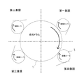
カラー電子写真システムでは、複数の色を使用するため転写残トナーにおける色味違いの問題が発生する。図1はカラー電子写真システムの2色目の画像形成ステーションにおける転写残トナーの機構について示したものである。
【0010】
カラー電子写真システムでは、各画像形成ステーションの感光ドラム上に形成したトナー像を、ベルト状の転写材搬送手段により担持搬送される転写材(例えば紙やOHPシート等)上に順次に重ねて転写していくものである。
【0011】
このような構成の画像形成装置においては、例えば、前のステーションで転写材上に転写されたトナーが、次のステーションに到達したときに次のステーションの感光ドラムに付着してしまう、いわゆる再転写が起きることがあり、次のステーションの転写残トナーに含まれる場合がある(図1においては転写後のドラム上のプラス極性のトナーが該当する)。
【0012】
前のステーションの転写トナーは、当然異なった色のトナーである(前のステーションの転写トナーを以後再転写トナーと呼ぶ)。これらが、帯電装置をぬけることでマイナスに帯電され、非画像部に残っているトナーは現像装置に回収されるが、感光ドラム上の画像部に残った異色の再転写トナーは現像部で回収されずそのまま画像部に残り現像され、色味の違ったゴーストとして画像に現れる。
【0013】
また、これを回収するために現像ローラを感光ドラムに対して逆方向に回転させ現像ニップに現像ローラに全て回収していたが、大量の再転写トナーが現像位置に突入してきたときに現像ニップ部でためることができずに再転写ゴーストが現れてしまう問題が生じた。
【0014】
本発明は、上記の従来技術を鑑みなされたもので、その目的とするところは、あらゆる条件で画像弊害がなく、再転写ゴーストがなく良好な画像を出力できる画像形成装置及びプロセスカートリッジを提供することである。
【0015】
本発明の他の目的は、再転写ゴーストを防止した画像形成装置及びプロセスカートリッジを提供することである。
【0016】
本発明の他の目的は、専用のクリーナをもたないクリーナレス方式に適した画像形成装置及びプロセスカートリッジを提供することである。
【0017】
本発明の他の目的は、像担持体上の残留現像剤を現像時に残らず除去するようにした画像形成装置及びプロセスカートリッジを提供することである。
【0018】
【課題を解決するための手段】
上記課題を解決するために、本発明は以下のような手段とした。
すなわち、本発明の画像形成装置は、第1の画像形成ステーションで受像部材へ第1の色の現像剤の像を転写した後、第2の画像形成ステーションで前記受像部材へ第2の色の現像剤の像を転写する転写手段と、
前記第1の画像形成ステーションには、第1の像担持体と、前記第1の像担持体を帯電する第1の帯電手段と、前記第1の色の現像剤を担持搬送し、前記第1の像担持体に形成された静電像を前記第1の色の現像剤で現像する第1の現像剤担持体と、が設けられ、
前記第2の画像形成ステーションには、第2の像担持体と、前記第2の像担持体を帯電する第2の帯電手段と、前記第2の色の現像剤を担持搬送し、前記第2の像担持体に形成された静電像を前記第2の色の現像剤で現像する第2の現像剤担持体と、が設けられた画像形成装置において、
前記第2の現像剤担持体は、現像動作と同時に前記第2の像担持体から残留現像剤を回収可能であり、
前記第2の現像剤担持体の移動方向は、現像位置において前記第2の像担持体の移動方向と逆方向であり、
前記第2の現像剤担持体位置は、前記第2の像担持体が時計回りに回転し、前記第2の像担持体の中心に対して、第四象限にあることを特徴とする。
【0019】
この構成によれば、前記第1の現像剤担持体は、前記第1の像担持体上の残留現像剤を、前記第1の現像剤担持体と前記第1の像担持体とのニップ部の前でせき止めることによって前記第1の現像剤担持体へ回収し、前記第2の現像剤担持体は、前記第2の像担持体上の前記残留現像剤を、前記第2の現像剤担持体と前記第2の像担持体とのニップ部の前でせき止めることによって前記第2の現像剤担持体へ回収し、また、現像剤担持体位置は、像担持体の中心から、像担持体の回転方向に対して第四象限の位置にあることで、現像ニップ部で残留現像剤のたまりを作り、現像剤担持体側に重力を利用して自然に落下する構成にすることにより、回収を確実におこなうことができ、大量の再転写トナーが突入してきたときでも、現像剤担持体へ確実に回収することにより、現像時の混色を防止した画像形成装置及びプロセスカートリッジを提供することができる。
【0020】
また、本発明の画像形成装置において、前記第2の帯電手段は、前記第2の像担持体に接触可能な第2の帯電部材を備え、
前記第2の帯電部材は、前記第2の像担持体上の前記残留現像剤を正規の極性に摩擦帯電することを特徴とする。
【0021】
更に、本発明の画像形成装置において、前記受像部材を前記第1の画像形成ステーションから前記第2の画像形成ステーションへ搬送する搬送手段を有することが好適である。
【0022】
更に、本発明の画像形成装置において、前記第2の現像剤担持体は、前記第2の像担持体に接触して設けられることが好適である。
【0023】
更に、本発明の画像形成装置において、前記第2の帯電部材は、AC電圧が印加されることなくDC電圧が印加されることが好適である。なぜならば、印加電圧がAC電圧とDC電圧との重畳電圧であると、AC電圧の作用により残留トナーを除電するからである。
【0024】
更に、本発明の画像形成装置において、前記第2の帯電部材は、前記第2の像担持体に対して周速差をもって回転可能であることが好適である。こうすることで、像担持体表面と現像剤担持体表面との間に周速差を設けて、かつニップ圧をもたせ、機械的にニップ前で再転写トナーをせき止めて再転写トナーの進行を阻害させ、現像装置に前のステーションの色の異なった再転写トナーを回収させる。
【0025】
更に、本発明のプロセスカートリッジは、第1の画像形成ステーションで受像部材へ第1の色の現像剤像を転写した後、第2の画像形成ステーションで前記受像部材へ第2の色の現像剤像を転写する転写手段を備える画像形成装置本体、の前記第2の画像形成ステーションに着脱可能なプロセスカートリッジにおいて、
前記プロセスカートリッジは、像担持体と、前記像担持体を帯電する帯電手段と、前記第2の色の現像剤とを担持搬送し、前記像担持体に形成された静電像を前記第2の色の現像剤で現像する現像剤担持体を具備し、
前記現像剤担持体は、現像動作と同時に前記像担持体から残留現像剤を回収可能であり、
前記現像剤担持体の移動方向は、現像位置において前記像担持体の移動方向と逆方向であり、
前記現像剤担持体位置は、前記像担持体の中心、且つ、前記像担持体の回転方向に対して第四象限にあることを特徴とする。
【0026】
【発明の実施の形態】
以下に図面を参照し、この発明の実施の形態について詳細に説明する。ただし、この実施の形態に記載されている構成部品の寸法、材質、形状、その相対配置などは、特に特定的な記載がない限りは、この発明の技術的範囲をそれらのみに限定する趣旨のものではない。また、以下の図面において、前述の従来技術の説明で用いた図面に記載された部材と同様の部材には同じ番号を付す。
【0027】
(第1の実施形態)
図3〜図7を参照して、第1の実施の形態に係る画像形成装置及びプロセスカートリッジについて説明する。
【0028】
図3に、本発明に係る画像形成装置の一例として、複数の現像装置をもつタンデム式のカラーレーザービームプリンタの概略構成を示す。なお、同図は、受像部材である転写材8の搬送方向に沿った縦断面図を示すものである。
【0029】
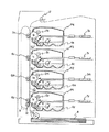
図3について説明すると、カラー画像形成装置は、転写材8を担持搬送するための転写材搬送手段である無端状に走行する転写ベルト9と、転写ベルト9の移動方向に各々異色のトナー像を形成する画像形成ステーションとしてのプロセスカートリッジP1,P2,P3,P4が直列に配置してある。各プロセスカートリッジ(画像形成部)は現像装置4y,4m,4c,4kに収納するトナーが異色であるだけで、基本的な構成作用に変わりはない。また、プロセスカートリッジは画像形成装置本体に着脱可能な構成である。
【0030】
ここで、画像形成手段としてのプロセスカートリッジP1乃至P4はイエロー(Y)、マゼンタ(M)、シアン(C)、ブラック(Bk)の4個の画像形成ユニットで構成され配設されている。そして、それぞれの画像形成ユニット部の構成は、像担持体である感光ドラム1y,1m,1c,1kが配置され、その外周部には各々一成分現像剤であるイエロートナー,マゼンタトナー,シアントナー,ブラックトナーを収納し、それらのトナーを搬送する現像剤担持体である現像ローラ5y,5m,5c,5kを具備した現像装置(現像手段)4y,4m,4c,4k、露光手段である3y、3m、3c、3k、帯電手段(帯電部材)である帯電ローラ2y,2m,2c,2k、が配設してある。また、転写ベルト9を挟んで各々の感光ドラム1に対向する部位に転写手段としての転写ローラ6y,6m,6c,6kが配設してある。
【0031】
この画像形成装置における転写材搬送手段は、適当な複数のローラに懸架されて走行する静電転写ベルト9であり、前記静電転写ベルト9の内部及び周囲には、転写ローラ6、吸着ローラ10を備えている。転写ローラ6は、後述する複数の画像形成部の一部として複数個配備されている。
【0032】
静電転写ベルト9の吸着ローラ10は、画像形成に先立って、給紙部から搬送された転写材8を静電転写ベルト9上に静電吸着する。各画像形成部P1乃至P4は、静電転写ベルト9上に静電吸着した転写材8が走行するにつれて、転写材8上の所定の位置に順次イエロートナー像,マゼンタトナー像,シアントナー像,ブラックトナー像が重なるようにタイミングをあわせて像形成を行い、順次重畳転写していく。
【0033】
以下に画像形成手順を画像形成ステーションとしてのプロセスカートリッジ(画像形成部ともいう)P1に着目して説明する。
【0034】
不図示の駆動手段により回転駆動する感光ドラム1yの表面感光層が、帯電バイアス−1150Vが印加された帯電ローラ2yによって一様に帯電される。帯電バイアスは交流電圧なしの直流電圧であり、感光ドラム1yの表面電位が−600Vとなるようにした。即ち、感光ドラム1yは、ドラム1yとローラ2yとの微小空隙における放電現象によって、ほぼ(印加直流電圧−放電開始電圧)の電位に帯電される。本実施例では放電開始電圧は約550Vであった。この感光ドラム1yの帯電面にイエロー成分による画像形成信号がレーザースキャナから投影されて静電潜像が形成される。
【0035】
この静電潜像が、感光ドラム1yの回転に伴って現像部位に達すると、現像バイアスにより現像ローラ4yからマイナス帯電極性のイエロートナーが前記潜像に付与されてイエロートナー像として反転現像される。このイエロートナー像はさらに感光ドラム1yの回転に伴って前記の転写部位へと送られる。
【0036】
このイエロートナー像が前記転写部位に達するタイミングにあわせて、あらかじめ転写ベルト9上に静電吸着された転写材8が搬送され、前記転写ローラ7yに印加される転写バイアス(プラス極性)によって、イエロートナー像は転写材8上に転移(転写)する。転写に寄与せず像担持体1上に残る残留トナーは帯電ローラ2yによって、現像装置に回収できる正規の極性(マイナス極性)に帯電される。また感光ドラムもマイナスに帯電される。転写後の感光ドラム上の残留トナーは正規の極性(マイナス極性)と逆の極性になっているものも多いが、帯電ローラ2yが放電を用いて帯電が行なわれることにより、強くマイナス極性に帯電される。
【0037】
なお、残留トナーを強くマイナスに帯電するために、帯電ローラ2yに印加される電圧はAC電圧なしのDC電圧であることが好ましい。なぜならば、印加電圧がAC電圧とDC電圧との重畳電圧であると、AC電圧の作用により残留トナーを除電するからである。
【0038】
また、感光ドラム上の残留トナーをより確実にマイナスに帯電するために、帯電ローラ2yの表面層は、トナーをマイナスに摩擦帯電する摩擦帯電極性を備えることが良い。即ち、帯電ローラによってトナーがマイナスに摩擦帯電するように帯電ローラ2yの表面層の材料とトナーの材料とを選択すれるのが良い。
【0039】
その後感光ドラムに残留トナーが存在したままの状態で、感光ドラムは、レーザスキャナにより画像情報に応じて光照射される。現像装置が潜像を現像するのと同時に、帯電ローラ2yにより正規の極性に帯電された残留トナーは現像装置に回収される。
そのとき、感光ドラム1yは次の画像形成動作に既に入っている。
【0040】
イエロートナー像を転写させた前記転写材8は、転写ベルト9の移動に伴いプロセスカートリッジ(画像形成部)P2に搬送される。転写材8が画像形成部P2に達する迄に、上記と同様に、レーザースキャナ3m及び現像ローラ5mにより、感光ドラム1m上にマゼンタトナー像が形成され、このトナー像が転写ローラ6mによって、前記のイエロートナー像に重畳転写される。この重畳トナー像を転写させた転写材8は、プロセスカートリッジ(画像形成部)P3に搬送される。
【0041】
同様に、画像形成部P3,P4で、レーザースキャナ3c,3k及び現像ローラ5c,5kにより、感光ドラム1c,1k上にシアントナー像,ブラックトナー像が形成され、転写ローラ6c,6kによって、前記の重畳トナー像に順次重畳転写されて転写行程が終了する。
【0042】
転写を終えた転写材8は、定着装置12に至り、ここで加熱,加圧されてトナー像が融解,混色されてカラー画像となり、転写材8に定着固定された後、機外に排出される。
【0043】
感光ドラム1yは、導電性の円筒状のドラム基体表面に感光層(例えば、有機光半導体、アモルファスシリコン等)を設けて構成したものである。感光ドラム1は、駆動手段(不図示)によって回転駆動され、その表面は所定の表面移動速度(以下周速度と略す。)で矢印方向に移動(回転)するようになっている。
【0044】
帯電ローラ2yは、芯金の外周面を弾性体で被覆した構成であり、弾性体の表面を感光ドラム1y表面に接触するようにして配置される。
【0045】
現像装置4yは、回転駆動される現像ローラ5yと、現像ローラ5y表面に担持されるトナーの層厚を規制する現像ブレードと、現像ローラ5yに新しいトナーを供給しながら、現像ローラ5yから古いトナーを剥ぎ取るために、現像ローラに対してカウンタに回転させるトナー供給ローラ7(図4参照)を現像装置4y内に配置している。トナー供給ローラは、現像ローラに圧接して設けられる。
【0046】
トナーとしては、磁性又は非磁性のいずれのトナーも使用することができ、またその製法についても重合、又は粉砕のいずれのものであってもよい。本実施の形態で使用したトナーは、摩擦により通常マイナスに帯電する負帯電性のものである。
【0047】
現像ローラ5y表面に塗布されるとともに現像ブレードによって層厚規制されたトナーは、電源(不図示)によって現像ローラ5yに−400Vの現像バイアス(DC電圧)を印加することにより、感光ドラム1y上の露光部に付着し、これにより静電潜像がトナー像として現像される。
【0048】
一方、トナー像転写後に感光ドラム表面に残った転写残トナー等の感光ドラム上残留物は、以下のようにして除去する。
【0049】
現像時に現像装置から感光ドラム表面に付着されたトナーは、マイナスに帯電している。このトナーは、転写時に転写ローラ4によって転写材の裏面がプラスに帯電され、その電界により転写材上に転写される。
【0050】
このとき感光ドラムもプラスに帯電を受けるため一部のトナーがプラスに帯電されてしまい、結果転写材に転写されずに感光ドラム上に残ってしまう。
【0051】
転写材8上に転写されないで感光ドラム1表面に残った感光ドラム上残留物は、プラスとマイナスとに帯電しているものがある。マイナスに帯電しているものは現像時に回収される。
【0052】
しかし、プラスに帯電している感光ドラム上残留物を現像時にバックコントラストによって回収するには、感光ドラム上残留物をマイナスに帯電する必要がある。これを、帯電ローラによって感光ドラム表面をマイナスに帯電するのと同時に行う。このようにして、感光ドラム上の残留物は元の現像装置へと回収される。
【0053】
ところが、2次色目、3次色目ステーションでは、現像ローラが感光ドラムに対して順方向に回転した場合、図1に示すように、再転写されたトナーが現像装置に現像同時回収されずそのまま画像部に残存してしまい、画像弊害が起きてしまう。
【0054】
そこで、本実施の形態ではこの再転写トナーの現像同時回収を以下のようにして行う。
【0055】
すなわち、本実施の形態において、図4に示すように、感光ドラム1と現像ローラ5を接触して設け、所定の周速度で回転する感光ドラム1の表面の移動方向に対して、感光ドラム1と現像ローラ5の接触部において逆方向(矢印方向)に回転させる。
【0056】
本実施の形態では、逆方向(カウンタ方向)で感光ドラムの周速に対して170%の周速で現像ローラを回転させた。こうすることで、図4に示すように、感光ドラム1表面と現像ローラ5表面との間に周速差を設けて、かつニップ圧をもたせ、機械的にニップ前で再転写トナーをせき止めて、再転写トナーの進行を阻害させ、現像装置に再転写トナーを回収させる。
【0057】
なお、現像ローラ5によって回収された感光ドラム上残留物は、撹拌部材によって現像装置4内で撹拌されて他のトナーと混合されて再利用されることになるが、再転写トナー(色の異なるトナー)は非常に少ないため、現像装置内で混合されることで画像上問題ないレベルとなる。
【0058】
次に再転写トナー量と色味違いゴーストのランクの関係を表1に示す。
【0059】
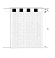
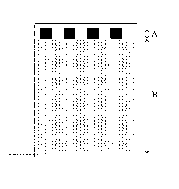
色味違いゴーストを評価するためのサンプル画像としては、図5に示すような、パターン画像を使用した。Aの領域に4cm角の正方形のべた黒画像を書き、Bの領域にハーフトーンパターンを書いた画像である。Aの領域には1次色目にイエローのみ画像形成パターンを形成し、Bの領域には2次色目にマゼンタのみ画像形成パターンを形成した。
【0060】
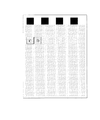
これにより、現像でイエロートナーが回収されない場合は、Bの領域にAの領域の画像パターンが現れて画像弊害となる。そこで、現像ローラを感光ドラムに対して順方向に回転させた場合と逆方向に回転させた場合の画像を出力した。なお、画像弊害のでるものは図6のように認識でき、Cの領域の濃度とDの領域の色味違いで画像を比較した。表1では、○は色味違いが認識できないランク、△は、多少色味違いが発生しているランク、×ははっきりと色味違いが認識できるランクである。
【0061】
【表1】
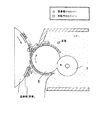
これをみると再転写トナー量0.4(mg/cm2)以上になると、色味違いゴーストが発生してしまう。通常、現像ニップ部では、トナーたまりがありバッファーの役目をして再転写トナーを現像器に回収している。またこのトナーたまりは図7(a)に示すように現像ローラと感光体ドラムの接触によってできている。これが、現像ローラ逆方向回転では、重力方向に対して現像ローラが下にある方が回収しやすくなる。また、それとは逆に図7(b)に示すように、現像ローラ逆方向回転では、ドラムが下にあるため、ドラム上に再転写トナーが残りやすく再転写ゴーストが現れやすい。表1に示した結果は、第1象限に現像ローラが位置したときの結果である。この場合、大量に再転写トナーがおそったときは、再転写トナーを完全に回収できずに色味違いゴーストが発生してしまう。
【0063】
そこで、現像位置を感光ドラムの回転方向に対して、図8に示すように各象限の位置で配置し、再転写トナー量と色味違いゴーストレベルを検討した。
その結果を表2に示す。
【0064】
【表2】
これより、第3,4象限に現像部を配置した系では、色味違いのゴーストを確認することはできなかった。これは、重力を利用し現像ローラ側に落下する構成にすることによって大量の再転写トナーが突入してきても確実に現像部に回収できるからである。
【0066】
ただし、第3象限に関しては、重力を利用しているもののトナーだまりができにくく、トナー飛散してしまう弊害があるため、第4象限のみが好ましいということがわかった。
【0067】
このように、感光ドラムの回転方向に対して現像位置を第四象限に配置した方が、色味の弊害もなく良好な画像が得られた。
【0068】
上述したように、本実施の形態では、クリーナレス方式のカラー画像形成において転写直後帯電前にブラシなどの補助部材を用いることなく、現像ローラと感光ドラムの対向部において、現像ローラ表面を感光ドラム表面の移動方向に対して逆方向に移動させる。結果、機械的にニップ前で再転写トナーをせき止めて、再転写トナーの進行を阻害させ、トナーたまりを作ることで再転写トナーを確実に現像装置に再転写トナーを回収させる。これにより、シンプルなカラークリーナレスシステムにおいて、再転写トナーの影響をなくした高画質な画像が得ることができた。
【0069】
なお、本実施の形態では、帯電装置、現像装置、感光ドラムが一体型になったプロセスカートリッジを使用したが、帯電装置もしくは現像装置を画像形成装置本体に具備してもよく、また各々の感光ドラムを画像形成装置本体に具備してもよい。
【0070】
また、上記画像形成装置にスキャナー等の画像入力手段と、コンピュータやサーバ等の制御手段を組み合わせた画像システムとしてもよい。
【0071】
(第2の実施形態)
図9には、第2の実施の形態が示されている。第2の実施の形態において、画像形成装置構成、現像装置構成は、第1の実施の形態と同一なので、同一の構成部分については同一の符号を付して、その説明は簡略し、本発明の特徴的な構成について説明を行う。
【0072】
第1の実施の形態では、帯電装置として感光ドラムに対して従動で回転する帯電ローラを用いた構成であった。しかし、本実施の形態においては、所定の周速度で回転する感光ドラムの表面に対して帯電ローラ表面を接触させ、さらに順方向に回転させてかつ周速度を異なるようにするか、又は逆方向に回転させる構成で行うものとする。
【0073】
このような構成においては、帯電ローラに転写残トナーが付着しても転写残トナーに対する帯電性能は劣化せず、長期間にわたって安定して転写残トナーを所望の極性に摩擦帯電させやすくなるため、再転写ゴースト等の画像弊害を生じることもない。本発明者の実験においては、1%以上の周速差を付けることで効果があることがわかっており、以上述べた周速差とは、周速度で1%以上の差のことをさすものである。
【0074】
第2の実施の形態では、帯電ローラ2yは感光ドラムの回転方向に対して順方向で回転させ、感光ドラムの周速に対して120%の周速で回転させた。このように、感光ドラム表面と帯電ローラ表面との間に周速差を設けることによって、帯電ローラ表面のトナーなどの汚染物を摺擦させ、摩擦帯電によってマイナスに帯電することが有効に行なえる。
【0075】
次に本実施の形態の構成について説明する。
【0076】
図9の装置本体の概略図に示すように、プロセスカートリッジP21、P22、P23、P24は、感光ドラム、帯電ローラ、現像ローラ、トナー容器を一体的に収納したものである。
【0077】
帯電ローラ22は感光ドラムの回転方向に対して順方向で回転させ、感光ドラムの周速に対して120%の周速で回転させた。このように、感光ドラム表面と帯電ローラ表面との間に周速差を設けることによって、帯電ローラ表面のトナーなどの汚染物を摺擦させ、摩擦帯電によってマイナスに帯電することが有効に行なえる。ここで、マイナスに帯電したトナーはある程度、帯電ローラと感光ドラムの電位差(例えば、帯電ローラ印加電圧1250V、感光ドラム電位−700V)によって感光ドラム表面に移動する。なお、実施例1と同様に帯電ローラは放電を用いて感光ドラムを帯電するものであり、この放電によってもトナーは強くマイナスに帯電されやすくなる。
【0078】
マイナスに帯電された転写残トナー(最転写トナーを含む)は、感光ドラム表面の移動方向に対し逆方向で回転する現像ローラに回収され、現像容器内に収容し撹拌部材でトナーが撹拌される。なお、再転写トナーは、非常に少ないため、現像装置内で混合されることで画像上問題ないレベルとなる。
【0079】
使用している部材は第2の実施の形態と同様なものを使用しているものとする。このような構成をとることによって第1の実施の形態と同様な効果が得られた。
【0080】
これにより、シンプルなカラークリーナレスシステムにおいて、帯電ローラへの転写残トナーによる汚染をも防止し、かつ、再転写トナーの影響をなくした高画質な画像が得ることができた。
【0081】
以上の実施の形態においては、全ての画像形成ステーションにおいて、同じ現像装置としていたが、1色目の画像形成ステーションにおいては、通常、再転写トナーが付着しにくいので、1色目の画像形成ステーションの現像装置においては上記現像装置に限られることもない。
【0082】
すなわち、1色目の画像形成ステーションにおいて、感光体の回転方向に対して現像ローラを順方向に回転することもできるし、感光体と現像ローラとを非接触として現像時に現像ローラ上のトナーを感光体へ飛翔させることもできる。
【0083】
ただし、転写ベルトによって1色目の像担持体に他の色のトナーが搬送されやすく1色目の像担持体に再転写トナーが付着しやすい場合には、実施の形態1、2のように1色目の画像形成ステーションの現像装置も他のステーションの現像装置と同じにすることが有効である。
【0084】
以上の実施の形態において、受像部材は転写材であり、転写材を転写ベルトで担持して各画像形成ステーションに搬送したが、受像部材を中間転写ベルトとして、各画像形成ステーションから中間転写ベルトに各色トナー像を重畳転写した後、中間転写ベルトから転写材へ重畳トナー像を一括転写するようにしても良い。
【0085】
以上説明したように、現像同時回収を行うシンプルなカラークリーナレスシステムにおいて、像担持体表面の移動方向に対し現像剤担持体を逆方向に回転させることで、再転写ゴースト等の画像弊害をなくすことが可能となる。
【0086】
本発明は以上の実施の形態に限定されるものではなく、本発明の技術思想の範囲内においてあらゆる変形が可能である。
【0087】
【発明の効果】
以上の説明で明らかなように、前記第1の現像剤担持体は、前記第1の像担持体上の残留現像剤を、前記第1の現像剤担持体と前記第1の像担持体とのニップ部の前でせき止めることによって前記第1の現像剤担持体へ回収し、前記第2の現像剤担持体は、前記第2の像担持体上の前記残留現像剤を、前記第2の現像剤担持体と前記第2の像担持体とのニップ部の前でせき止めることによって前記第2の現像剤担持体へ回収し、また、現像剤担持体位置は、像担持体の中心から、像担持体の回転方向に対して第四象限の位置にあることで、現像ニップ部で残留現像剤のたまりを作り、現像剤担持体側に重力を利用して自然に落下する構成にすることにより、回収を確実におこなうことができ、大量の再転写トナーが突入してきたときでも、現像剤担持体へ確実に回収することにより、現像時の混色を防止した画像形成装置及びプロセスカートリッジを提供できる。
【0088】
更に、再転写ゴーストを防止した画像形成装置及びプロセスカートリッジを提供することができる。
【0089】
更に、専用のクリーナをもたないクリーナレス方式に適した画像形成装置及びプロセスカートリッジを提供することができる。
【0090】
更に、像担持体上の残留現像剤を現像時に残らず除去するようにした画像形成装置及びプロセスカートリッジを提供することができる。
【図面の簡単な説明】
【図1】従来の画像形成装置の概略断面図である。
【図2】カラー電子写真システムの2次色目のステーションにおける転写残トナーの機構について示したものである。
【図3】第1の実施の形態に係る画像形成装置の断面図である。
【図4】第1の実施の形態に係る画像形成装置における再転写トナーの回収の様子を示した模式図である。
【図5】画像弊害を確認するためのパターン画像を示した図である。
【図6】再転写ゴーストが現れたパターン画像を示した図である。
【図7】ドラムと現像のニップ部を表した図である。
【図8】現像位置とドラム位置を示した図である。
【図9】第2の実施の形態に係る画像形成装置の断面図である。
【符号の説明】
1,1y,1m,1c,1k 感光ドラム(像担持体)
2,2y,2m,2c,2k 帯電ローラ(帯電部材)
3,3y,3m,3c,3k 露光手段
4,4y,4m,4c,4k 現像装置(現像手段)
5,5y,5m,5c,5k 現像ローラ(現像剤担持体)
6,6y,6m,6c,6k 感光ドラム
7 トナー供給ローラ
8 転写材
9 転写ベルト
10 吸着ローラ
12 定着装置
13 摺擦部材
P1,P2,P3,P4 プロセスカートリッジ[0001]
TECHNICAL FIELD OF THE INVENTION
BACKGROUND OF THE INVENTION 1. Field of the Invention The present invention relates to a color image forming apparatus such as a laser beam printer or an electrophotographic copying machine, and a process cartridge detachably mountable to a main body of the apparatus, and more particularly to a cleanerless color image forming apparatus having a plurality of developing devices. And a process cartridge.
[0002]
[Prior art]
2. Description of the Related Art Conventionally, in an image forming apparatus such as an electrophotographic copying machine or a laser beam printer, generally, a charging process for uniformly and uniformly charging an image carrier such as a photosensitive drum is performed. An exposure process for writing a latent image, a development process for attaching toner to an electrostatic latent image to develop it as a toner image, a transfer process for transferring a toner image on an image carrier to a transfer material such as paper, and a toner image on a transfer material The image is formed by a series of image forming processes including a fixing process for fixing the toner image, a cleaning process for removing a residue such as a transfer residual toner remaining on the surface of the image carrier after the transfer of the toner image, and the like.
[0003]
In the above-described cleaning process, the transfer residual toner collected by the cleaning device is stored in a container for disposal, and then disposed.
[0004]
Therefore, in recent years, a cleaner-less process has been proposed in which the image forming apparatus is reduced in size by omitting the above-described cleaning device, and maintenance such as discarding transfer residual toner is not required. In one embodiment of the cleanerless process, the developing device attaches the toner to the exposed portion of the image carrier whose surface potential is attenuated by reversal development, and simultaneously removes the residue remaining in the non-exposed portion. We are collecting.
[0005]
Specifically, in the case of a one-component developer composed of a negatively chargeable toner, the image carrier is uniformly charged to −600 V in the charging step, and a portion corresponding to the image portion of the image carrier is exposed in the exposure step. Exposure is performed to attenuate the surface potential so that the exposed portion becomes -200 V. If a DC voltage of -400 V is applied to the developer carrier as a developing bias in the developing process, the negatively charged residual toner is removed from the image portion. In the exposed portion corresponding to the above, the toner remains on the image carrier as it is, but in the non-exposed portion, the toner is collected by the developing device due to the back contrast. It can be used again.
[0006]
In the recent laser beam printer market, color laser printers have become mainstream.
[0007]
What is needed is an inexpensive and compact color printer as well as a monochrome printer. Therefore, it has become necessary to construct a simple electrophotographic system.
[0008]
[Problems to be solved by the invention]
However, when the cleanerless system used in the monochrome electrophotographic system in the related art as described above is applied to a full-color electrophotographic system, the following problems occur.
[0009]
In the color electrophotographic system, a plurality of colors are used, so that there is a problem of a difference in color of the transfer residual toner. FIG. 1 shows the mechanism of the transfer residual toner in the second color image forming station of the color electrophotographic system.
[0010]
In a color electrophotographic system, a toner image formed on a photosensitive drum in each image forming station is sequentially transferred onto a transfer material (for example, paper or an OHP sheet) carried and conveyed by a belt-shaped transfer material conveying means. It is something to do.
[0011]
In the image forming apparatus having such a configuration, for example, the so-called re-transfer, in which the toner transferred on the transfer material in the previous station adheres to the photosensitive drum of the next station when it reaches the next station. May occur and may be included in the transfer residual toner of the next station (in FIG. 1, the toner having the positive polarity on the drum after the transfer corresponds).
[0012]
The transfer toner of the previous station is, of course, a toner of a different color (the transfer toner of the previous station is hereinafter referred to as retransfer toner). These are negatively charged by removing the charging device, and the toner remaining in the non-image area is collected by the developing device, but the re-transferred toner of a different color remaining in the image area on the photosensitive drum is collected by the developing unit. Instead, it remains in the image portion and is developed, and appears in the image as a ghost having a different color.
[0013]
In order to collect the toner, the developing roller was rotated in the opposite direction to the photosensitive drum, and all of the toner was collected in the developing nip.However, when a large amount of retransferred toner entered the developing position, the developing nip was stopped. There was a problem that retransfer ghosts appeared because they could not be accumulated at the portion.
[0014]
An object of the present invention is to provide an image forming apparatus and a process cartridge capable of outputting a good image without image harm under all conditions and without retransfer ghosts. That is.
[0015]
Another object of the present invention is to provide an image forming apparatus and a process cartridge in which a retransfer ghost is prevented.
[0016]
It is another object of the present invention to provide an image forming apparatus and a process cartridge suitable for a cleanerless system having no dedicated cleaner.
[0017]
Another object of the present invention is to provide an image forming apparatus and a process cartridge in which a residual developer on an image carrier is completely removed during development.
[0018]
[Means for Solving the Problems]
In order to solve the above problems, the present invention has the following means.
That is, the image forming apparatus of the present invention transfers the image of the developer of the first color to the image receiving member at the first image forming station, and then transfers the image of the second color to the image receiving member at the second image forming station. Transfer means for transferring the image of the developer,
The first image forming station has a first image carrier, a first charging unit for charging the first image carrier, and a carrier for carrying the first color developer. A first developer carrier for developing the electrostatic image formed on the first image carrier with the developer of the first color;
The second image forming station carries a second image carrier, a second charging unit for charging the second image carrier, and carries and transports the developer of the second color. And a second developer carrier for developing the electrostatic image formed on the second image carrier with the developer of the second color.
The second developer carrier can collect the residual developer from the second image carrier at the same time as the developing operation,
The direction of movement of the second developer carrier is opposite to the direction of movement of the second image carrier at the development position,
The position of the second developer carrier is such that the second image carrier rotates clockwise and is located in a fourth quadrant with respect to the center of the second image carrier.
[0019]
According to this configuration, the first developer carrier removes the residual developer on the first image carrier into a nip portion between the first developer carrier and the first image carrier. And collects the residual developer on the second image carrier by the second developer carrier by collecting the first developer carrier by damming in front of the second developer carrier. The developer is recovered to the second developer carrier by damping in front of a nip portion between the image carrier and the second image carrier, and the position of the developer carrier is moved from the center of the image carrier to the image carrier. Is located in the fourth quadrant with respect to the rotation direction of the developer, a pool of the residual developer is formed in the developing nip portion, and the developer is naturally dropped by using gravity on the developer carrier side, so that the recovery is performed. It can be performed reliably, and even when a large amount of retransfer toner enters, the developer carrier By reliably collected, it is possible to provide an image forming apparatus and a process cartridge to prevent color mixing at the time of development.
[0020]
Further, in the image forming apparatus of the present invention, the second charging unit includes a second charging member that can contact the second image carrier.
The second charging member frictionally charges the residual developer on the second image carrier to a regular polarity.
[0021]
Further, in the image forming apparatus according to the present invention, it is preferable that the image forming apparatus further includes a transport unit that transports the image receiving member from the first image forming station to the second image forming station.
[0022]
Further, in the image forming apparatus of the present invention, it is preferable that the second developer carrier is provided in contact with the second image carrier.
[0023]
Further, in the image forming apparatus of the present invention, it is preferable that the second charging member is applied with a DC voltage without being applied with an AC voltage. This is because, if the applied voltage is a superimposed voltage of the AC voltage and the DC voltage, the residual toner is removed by the action of the AC voltage.
[0024]
Further, in the image forming apparatus of the present invention, it is preferable that the second charging member is rotatable with a peripheral speed difference with respect to the second image carrier. By doing so, a peripheral speed difference is provided between the surface of the image carrier and the surface of the developer carrier, and a nip pressure is provided, so that the retransfer toner is mechanically damped before the nip to advance the retransfer toner. And cause the developing device to collect re-transferred toner of a different color from the previous station.
[0025]
Further, the process cartridge of the present invention further comprises a second image forming station which transfers the first color developer image to the image receiving member at the first image forming station, and then transfers the second color developer image to the image receiving member at the second image forming station. A process cartridge detachable from the second image forming station of an image forming apparatus main body including a transfer unit for transferring an image,
The process cartridge carries and conveys an image carrier, a charging unit for charging the image carrier, and a developer of the second color, and transfers the electrostatic image formed on the image carrier to the second color. A developer carrying member for developing with a developer of a color of
The developer carrier can collect the residual developer from the image carrier at the same time as the developing operation,
The moving direction of the developer carrier is opposite to the moving direction of the image carrier at the developing position,
The developer carrier is located at the center of the image carrier and in the fourth quadrant with respect to the rotation direction of the image carrier.
[0026]
BEST MODE FOR CARRYING OUT THE INVENTION
Hereinafter, embodiments of the present invention will be described in detail with reference to the drawings. However, the dimensions, materials, shapes, relative arrangements, and the like of the components described in this embodiment are not intended to limit the technical scope of the present invention to them unless otherwise specified. Not something. Further, in the following drawings, the same members as those described in the drawings used in the description of the related art described above are denoted by the same reference numerals.
[0027]
(1st Embodiment)
An image forming apparatus and a process cartridge according to the first embodiment will be described with reference to FIGS.
[0028]
FIG. 3 shows a schematic configuration of a tandem type color laser beam printer having a plurality of developing devices as an example of the image forming apparatus according to the present invention. FIG. 1 is a longitudinal sectional view of the
[0029]
Referring to FIG. 3, the color image forming apparatus is configured to transfer an
[0030]
Here, the process cartridges P1 to P4 as image forming means are constituted by four image forming units of yellow (Y), magenta (M), cyan (C), and black (Bk). Each of the image forming units has a configuration in which
[0031]
The transfer material transporting means in this image forming apparatus is an
[0032]
The attraction roller 10 of the
[0033]
Hereinafter, the image forming procedure will be described focusing on a process cartridge (also referred to as an image forming unit) P1 as an image forming station.
[0034]
The surface photosensitive layer of the photosensitive drum 1y rotated and driven by a driving unit (not shown) is uniformly charged by the charging
[0035]
When this electrostatic latent image reaches the developing site with the rotation of the photosensitive drum 1y, a yellow toner having a negative charge polarity is applied to the latent image from the developing
[0036]
The
[0037]
The voltage applied to the charging
[0038]
Further, in order to more reliably negatively charge the residual toner on the photosensitive drum, the surface layer of the charging
[0039]
Thereafter, the photosensitive drum is irradiated with light according to image information by a laser scanner while the residual toner remains on the photosensitive drum. At the same time as the developing device develops the latent image, the residual toner charged to the normal polarity by the charging
At that time, the photosensitive drum 1y has already entered the next image forming operation.
[0040]
The
[0041]
Similarly, in the image forming units P3 and P4, a cyan toner image and a black toner image are formed on the
[0042]
After the transfer, the
[0043]
The photosensitive drum 1y is configured by providing a photosensitive layer (for example, an organic optical semiconductor, amorphous silicon, or the like) on the surface of a conductive cylindrical drum base. The photosensitive drum 1 is driven to rotate by driving means (not shown), and its surface moves (rotates) in a direction indicated by an arrow at a predetermined surface moving speed (hereinafter abbreviated as a peripheral speed).
[0044]
The charging
[0045]
The developing
[0046]
As the toner, either magnetic or non-magnetic toner can be used, and the production method thereof may be either polymerization or pulverization. The toner used in the exemplary embodiment is a negatively chargeable toner that is normally negatively charged by friction.
[0047]
The toner applied to the surface of the developing
[0048]
On the other hand, residues on the photosensitive drum such as transfer residual toner remaining on the surface of the photosensitive drum after the transfer of the toner image are removed as follows.
[0049]
The toner attached to the surface of the photosensitive drum from the developing device during the development is negatively charged. The back surface of the transfer material is positively charged by the transfer roller 4 during transfer, and is transferred onto the transfer material by the electric field.
[0050]
At this time, since the photosensitive drum is also positively charged, a part of the toner is positively charged, and as a result, the toner remains on the photosensitive drum without being transferred to the transfer material.
[0051]
Some of the residues on the photosensitive drum 1 remaining on the surface of the photosensitive drum 1 without being transferred onto the
[0052]
However, in order to recover the positively charged residue on the photosensitive drum by the back contrast during development, it is necessary to negatively charge the residue on the photosensitive drum. This is performed at the same time as the surface of the photosensitive drum is negatively charged by the charging roller. In this way, the residue on the photosensitive drum is recovered to the original developing device.
[0053]
However, at the secondary color and tertiary color stations, when the developing roller rotates in the forward direction with respect to the photosensitive drum, as shown in FIG. This will cause the image to be adversely affected.
[0054]
Therefore, in the present embodiment, the simultaneous recovery of the re-transferred toner is carried out as follows.
[0055]
That is, in the present embodiment, as shown in FIG. 4, the photosensitive drum 1 and the developing
[0056]
In this embodiment, the developing roller is rotated in the opposite direction (counter direction) at a peripheral speed of 170% of the peripheral speed of the photosensitive drum. By doing so, as shown in FIG. 4, a peripheral speed difference is provided between the surface of the photosensitive drum 1 and the surface of the developing
[0057]
The residue on the photosensitive drum collected by the developing
[0058]
Next, Table 1 shows the relationship between the retransfer toner amount and the rank of the ghost having a different color.
[0059]
A pattern image as shown in FIG. 5 was used as a sample image for evaluating a different color ghost. This is an image in which a 4 cm square solid black image is written in the area A and a halftone pattern is written in the area B. In the area A, a yellow-only image forming pattern was formed in the primary color, and in the area B, a magenta-only image forming pattern was formed in the secondary color.
[0060]
As a result, when the yellow toner is not collected in the development, the image pattern of the area A appears in the area B, which causes an image problem. Therefore, images were output when the developing roller was rotated in the forward direction with respect to the photosensitive drum and when the developing roller was rotated in the reverse direction. It should be noted that the image adverse effects can be recognized as shown in FIG. 6, and the images were compared based on the density of the area C and the difference in the color of the area D. In Table 1, ○ indicates a rank in which a difference in color is not recognized, Δ indicates a rank in which a difference in color is slightly generated, and X indicates a rank in which a difference in color is clearly recognized.
[0061]
[Table 1]
It can be seen that the retransfer toner amount is 0.4 (mg / cm 2 Above), ghosts with different colors are generated. Normally, in the developing nip portion, there is a pool of toner, which serves as a buffer and collects the retransferred toner to the developing device. This toner accumulation is formed by the contact between the developing roller and the photosensitive drum as shown in FIG. However, when the developing roller is rotated in the reverse direction, it is easier to collect when the developing roller is below the direction of gravity. On the contrary, as shown in FIG. 7B, when the developing roller is rotated in the reverse direction, the retransfer toner tends to remain on the drum because the drum is below, and a retransfer ghost is likely to appear. The results shown in Table 1 are obtained when the developing roller is located in the first quadrant. In this case, when a large amount of retransferred toner is used, the retransferred toner cannot be completely recovered, and a ghost with a different color is generated.
[0063]
Therefore, the developing position was arranged at each quadrant position as shown in FIG. 8 with respect to the rotation direction of the photosensitive drum, and the retransfer toner amount and the color difference ghost level were examined.
Table 2 shows the results.
[0064]
[Table 2]
As a result, in the system in which the developing units were arranged in the third and fourth quadrants, it was not possible to confirm ghosts with different colors. This is because, by employing a configuration in which the toner is dropped to the developing roller using gravity, even if a large amount of retransfer toner enters, the toner can be reliably collected in the developing unit.
[0066]
However, in the third quadrant, it was found that only the fourth quadrant was preferable because gravity was used, but there was a problem that toner accumulation was difficult and toner was scattered.
[0067]
As described above, when the developing position was arranged in the fourth quadrant with respect to the rotation direction of the photosensitive drum, a good image was obtained without any adverse effect on the tint.
[0068]
As described above, in the present embodiment, in the cleanerless color image formation, the surface of the developing roller is contacted with the photosensitive drum at the opposing portion between the developing roller and the photosensitive drum without using an auxiliary member such as a brush immediately before transfer and before charging. Move in the opposite direction to the direction of surface movement. As a result, the retransferred toner is mechanically damped before the nip to hinder the progress of the retransferred toner, and the toner is formed, so that the retransferred toner is reliably collected by the developing device. As a result, in a simple color cleanerless system, a high-quality image free of the influence of retransfer toner could be obtained.
[0069]
In the present embodiment, the process cartridge in which the charging device, the developing device, and the photosensitive drum are integrated is used. However, the charging device or the developing device may be provided in the main body of the image forming apparatus. The drum may be provided in the image forming apparatus main body.
[0070]
Further, an image system in which the image forming apparatus is combined with an image input unit such as a scanner and a control unit such as a computer or a server may be used.
[0071]
(Second embodiment)
FIG. 9 shows a second embodiment. In the second embodiment, since the configuration of the image forming apparatus and the configuration of the developing apparatus are the same as those of the first embodiment, the same components are denoted by the same reference numerals, and the description thereof will be simplified. The characteristic configuration of will be described.
[0072]
In the first embodiment, the charging device is configured to use a charging roller that rotates following the photosensitive drum. However, in the present embodiment, the surface of the charging roller is brought into contact with the surface of the photosensitive drum rotating at a predetermined peripheral speed, and is further rotated in the forward direction and the peripheral speed is changed, or It is assumed that the rotation is performed in the following manner.
[0073]
In such a configuration, even if the transfer residual toner adheres to the charging roller, the charging performance for the transfer residual toner does not deteriorate, and it becomes easy to stably frictionally charge the transfer residual toner to a desired polarity over a long period of time. No adverse effects such as retransfer ghosts occur. In experiments conducted by the present inventor, it has been found that providing a peripheral speed difference of 1% or more is effective, and the peripheral speed difference described above refers to a difference of 1% or more in peripheral speed. It is.
[0074]
In the second embodiment, the charging
[0075]
Next, the configuration of the present embodiment will be described.
[0076]
9, the process cartridges P21, P22, P23, and P24 integrally house a photosensitive drum, a charging roller, a developing roller, and a toner container.
[0077]
The charging
[0078]
The negatively charged transfer residual toner (including the most-transferred toner) is collected by a developing roller that rotates in a direction opposite to the direction of movement of the photosensitive drum surface, is accommodated in a developing container, and is stirred by a stirring member. . Since the amount of retransferred toner is very small, the retransferred toner is mixed in the developing device to a level at which there is no problem on the image.
[0079]
It is assumed that the same members as those used in the second embodiment are used. With such a configuration, the same effect as in the first embodiment is obtained.
[0080]
As a result, in a simple color cleaner-less system, it was possible to prevent contamination of the charging roller by toner remaining after transfer, and to obtain a high-quality image without the influence of retransfer toner.
[0081]
In the above embodiment, the same developing device is used in all the image forming stations. However, in the first color image forming station, the re-transfer toner is usually difficult to adhere, so The device is not limited to the developing device.
[0082]
That is, in the image forming station for the first color, the developing roller can be rotated in the forward direction with respect to the rotating direction of the photoconductor, or the toner on the developing roller is exposed at the time of development by leaving the photoconductor and the developing roller out of contact. You can also fly to the body.
[0083]
However, when the toner of another color is easily transported to the image carrier of the first color by the transfer belt and the retransfer toner easily adheres to the image carrier of the first color, the first color image carrier is used as in the first and second embodiments. It is effective to make the developing device of the image forming station the same as the developing devices of the other stations.
[0084]
In the above embodiment, the image receiving member is a transfer material, and the transfer material is carried on the transfer belt and conveyed to each image forming station. After the respective color toner images are superimposedly transferred, the superimposed toner images may be collectively transferred from the intermediate transfer belt to the transfer material.
[0085]
As described above, in a simple color cleanerless system for simultaneous recovery of development, by rotating the developer carrier in a direction opposite to the moving direction of the image carrier surface, image harm such as retransfer ghost is eliminated. It becomes possible.
[0086]
The present invention is not limited to the above embodiments, and various modifications are possible within the scope of the technical idea of the present invention.
[0087]
【The invention's effect】
As is apparent from the above description, the first developer carrier carries the residual developer on the first image carrier with the first developer carrier and the first image carrier. The first developer carrier is collected by damming in front of the nip portion, and the second developer carrier transfers the residual developer on the second image carrier to the second image carrier. The developer carrier and the second image carrier are collected in the second developer carrier by damming in front of the nip portion, and the position of the developer carrier is from the center of the image carrier, By being in the fourth quadrant position with respect to the rotation direction of the image carrier, a pool of residual developer is formed at the developing nip portion, and the structure is such that the developer drops naturally using gravity on the developer carrier side. Can be reliably collected, and even when a large amount of retransfer toner enters, the current Agent by reliably collected into carrier, it is possible to provide an image forming apparatus and a process cartridge to prevent color mixing at the time of development.
[0088]
Further, it is possible to provide an image forming apparatus and a process cartridge in which a retransfer ghost is prevented.
[0089]
Further, it is possible to provide an image forming apparatus and a process cartridge suitable for a cleanerless system having no dedicated cleaner.
[0090]
Further, it is possible to provide an image forming apparatus and a process cartridge in which the residual developer on the image carrier is completely removed during development.
[Brief description of the drawings]
FIG. 1 is a schematic sectional view of a conventional image forming apparatus.
FIG. 2 illustrates a mechanism of a transfer residual toner in a station of a secondary color of a color electrophotographic system.
FIG. 3 is a cross-sectional view of the image forming apparatus according to the first embodiment.
FIG. 4 is a schematic view showing a state of collecting retransfer toner in the image forming apparatus according to the first embodiment.
FIG. 5 is a diagram showing a pattern image for confirming an image defect.
FIG. 6 is a diagram illustrating a pattern image in which a retransfer ghost appears.
FIG. 7 is a diagram illustrating a nip portion of a drum and a development.
FIG. 8 is a diagram showing a developing position and a drum position.
FIG. 9 is a sectional view of an image forming apparatus according to a second embodiment.
[Explanation of symbols]
1,1y, 1m, 1c, 1k Photosensitive drum (image carrier)
2,2y, 2m, 2c, 2k Charging roller (charging member)
3,3y, 3m, 3c, 3k Exposure means
4,4y, 4m, 4c, 4k developing device (developing means)
5,5y, 5m, 5c, 5k developing roller (developer carrier)
6,6y, 6m, 6c, 6k photosensitive drum
7 Toner supply roller
8 Transfer material
9 Transfer belt
10 Suction roller
12 Fixing device
13 Sliding member
P1, P2, P3, P4 Process cartridge
Claims (7)
前記第1の画像形成ステーションには、第1の像担持体と、前記第1の像担持体を帯電する第1の帯電手段と、前記第1の色の現像剤を担持搬送し、前記第1の像担持体に形成された静電像を前記第1の色の現像剤で現像する第1の現像剤担持体と、が設けられ、
前記第2の画像形成ステーションには、第2の像担持体と、前記第2の像担持体を帯電する第2の帯電手段と、前記第2の色の現像剤を担持搬送し、前記第2の像担持体に形成された静電像を前記第2の色の現像剤で現像する第2の現像剤担持体と、が設けられた画像形成装置において、
前記第2の現像剤担持体は、現像動作と同時に前記第2の像担持体から残留現像剤を回収可能であり、
前記第2の現像剤担持体の移動方向は、現像位置において前記第2の像担持体の移動方向と逆方向であり、
前記第2の現像剤担持体位置は、前記第2の像担持体が時計回りに回転し、前記第2の像担持体の中心に対して、第四象限にあることを特徴とする画像形成装置。Transfer means for transferring the first color developer image to the image receiving member at the first image forming station, and then transferring the second color developer image to the image receiving member at the second image forming station; ,
The first image forming station has a first image carrier, a first charging unit for charging the first image carrier, and a carrier for carrying the first color developer. A first developer carrier for developing the electrostatic image formed on the first image carrier with the developer of the first color;
The second image forming station carries a second image carrier, a second charging unit for charging the second image carrier, and carries and transports the developer of the second color. And a second developer carrier for developing the electrostatic image formed on the second image carrier with the developer of the second color.
The second developer carrier can collect the residual developer from the second image carrier at the same time as the developing operation,
The direction of movement of the second developer carrier is opposite to the direction of movement of the second image carrier at the development position,
The second developer carrier is located in a fourth quadrant with respect to the center of the second image carrier when the second image carrier rotates clockwise. apparatus.
前記第2の帯電部材は、前記第2の像担持体上の前記残留現像剤を正規の極性に摩擦帯電することを特徴とする請求項1記載の画像形成装置。The second charging unit includes a second charging member that can contact the second image carrier,
The image forming apparatus according to claim 1, wherein the second charging member frictionally charges the residual developer on the second image carrier to a normal polarity.
前記プロセスカートリッジは、像担持体と、前記像担持体を帯電する帯電手段と、前記第2の色の現像剤とを担持搬送し、前記像担持体に形成された静電像を前記第2の色の現像剤で現像する現像剤担持体を具備し、
前記現像剤担持体は、現像動作と同時に前記像担持体から残留現像剤を回収可能であり、
前記現像剤担持体の移動方向は、現像位置において前記像担持体の移動方向と逆方向であり、
前記現像剤担持体位置は、前記像担持体の中心、且つ、前記像担持体の回転方向に対して第四象限にあることを特徴とするプロセスカートリッジ。An image including transfer means for transferring a developer image of a first color to an image receiving member at a first image forming station and then transferring a developer image of a second color to the image receiving member at a second image forming station; A process cartridge detachable from the second image forming station of the forming apparatus main body;
The process cartridge carries and conveys an image carrier, a charging unit for charging the image carrier, and a developer of the second color, and transfers the electrostatic image formed on the image carrier to the second color. A developer carrying member for developing with a developer of a color of
The developer carrier can collect the residual developer from the image carrier at the same time as the developing operation,
The moving direction of the developer carrier is opposite to the moving direction of the image carrier at the developing position,
The process cartridge according to claim 1, wherein the developer carrier is located at a center of the image carrier and in a fourth quadrant with respect to a rotation direction of the image carrier.
Priority Applications (1)
| Application Number | Priority Date | Filing Date | Title |
|---|---|---|---|
| JP2003020724A JP2004233553A (en) | 2003-01-29 | 2003-01-29 | Image forming apparatus and processing cartridge |
Applications Claiming Priority (1)
| Application Number | Priority Date | Filing Date | Title |
|---|---|---|---|
| JP2003020724A JP2004233553A (en) | 2003-01-29 | 2003-01-29 | Image forming apparatus and processing cartridge |
Publications (1)
| Publication Number | Publication Date |
|---|---|
| JP2004233553A true JP2004233553A (en) | 2004-08-19 |
Family
ID=32950275
Family Applications (1)
| Application Number | Title | Priority Date | Filing Date |
|---|---|---|---|
| JP2003020724A Withdrawn JP2004233553A (en) | 2003-01-29 | 2003-01-29 | Image forming apparatus and processing cartridge |
Country Status (1)
| Country | Link |
|---|---|
| JP (1) | JP2004233553A (en) |
Cited By (1)
| Publication number | Priority date | Publication date | Assignee | Title |
|---|---|---|---|---|
| US10401779B2 (en) | 2017-08-28 | 2019-09-03 | Canon Kabushiki Kaisha | Image forming apparatus |
-
2003
- 2003-01-29 JP JP2003020724A patent/JP2004233553A/en not_active Withdrawn
Cited By (1)
| Publication number | Priority date | Publication date | Assignee | Title |
|---|---|---|---|---|
| US10401779B2 (en) | 2017-08-28 | 2019-09-03 | Canon Kabushiki Kaisha | Image forming apparatus |
Similar Documents
| Publication | Publication Date | Title |
|---|---|---|
| JP2008180902A (en) | Image forming device | |
| JP2001166609A (en) | Image forming device | |
| JP2001312114A (en) | Image forming device | |
| JP2009128459A (en) | Image forming apparatus | |
| JP2008074506A (en) | Recording material carrying device and image forming device | |
| US6721522B2 (en) | Process cartridge detachably mountable to a main assembly of an image forming apparatus comprising transferring means for transferring a color developer image onto the image receiving material and such an image forming apparatus | |
| JP2004191766A (en) | Image forming device | |
| JP4289873B2 (en) | Image forming apparatus | |
| JP2004233553A (en) | Image forming apparatus and processing cartridge | |
| JP2003228214A (en) | Image forming apparatus | |
| JP3434413B2 (en) | Image forming device | |
| JP2004233552A (en) | Image forming apparatus and processing cartridge | |
| JPH11249428A (en) | Developing device | |
| JPH11202709A (en) | Image formation device | |
| JP2003114560A (en) | Image forming device and process cartridge | |
| JP4092056B2 (en) | Image forming apparatus | |
| JP2004212570A (en) | Image forming apparatus | |
| JP3472037B2 (en) | Image forming device | |
| JPH11202642A (en) | Image forming device | |
| JP2003295629A (en) | Image forming apparatus | |
| JP2006189619A (en) | Image forming apparatus | |
| JP3306267B2 (en) | Image forming device | |
| JPH11296001A (en) | Wet type image forming device | |
| JP2003323062A (en) | Image forming device | |
| JPH09297519A (en) | Image forming device |
Legal Events
| Date | Code | Title | Description |
|---|---|---|---|
| A300 | Application deemed to be withdrawn because no request for examination was validly filed |
Free format text: JAPANESE INTERMEDIATE CODE: A300 Effective date: 20060404 |