JP2004233544A - Method for washing substrate for electrophotographic photoreceptor and method for manufacturing electrophotographic photoreceptor - Google Patents
Method for washing substrate for electrophotographic photoreceptor and method for manufacturing electrophotographic photoreceptor Download PDFInfo
- Publication number
- JP2004233544A JP2004233544A JP2003020688A JP2003020688A JP2004233544A JP 2004233544 A JP2004233544 A JP 2004233544A JP 2003020688 A JP2003020688 A JP 2003020688A JP 2003020688 A JP2003020688 A JP 2003020688A JP 2004233544 A JP2004233544 A JP 2004233544A
- Authority
- JP
- Japan
- Prior art keywords
- substrate
- cleaning
- photosensitive member
- electrophotographic photosensitive
- liquid
- Prior art date
- Legal status (The legal status is an assumption and is not a legal conclusion. Google has not performed a legal analysis and makes no representation as to the accuracy of the status listed.)
- Withdrawn
Links
Images


Landscapes
- Photoreceptors In Electrophotography (AREA)
Abstract
Description
【0001】
【発明の属する技術分野】
本発明は、電子写真感光体における感光層を形成する対象となる電子写真感光体用基体の洗浄方法及び電子写真感光体の製造方法に関するものである。
【0002】
【従来の技術】
電子写真感光体用基体(以下、必要に応じて基体という)は、加工時に加工油、潤滑油、防錆油などが用いられる。そのため、加工後の基体には必ず油分が残留しており、加えて切削粉や空気中の粉塵、ハンドリング時の人由来の異物などが付着するため、これらの付着物を洗浄してから基体を用いる必要がある。
【0003】
基体の洗浄方法としては、溶剤、準水系洗浄剤、水系洗浄剤、または純水を用いて洗浄する方法があるが、現在は、オゾン層破壊や地球温暖化、大気汚染などの環境問題及び人体への悪影響などを考慮して塩素系溶剤の削減、全面廃止の方向に移行しており、水系洗浄剤または純水を用いた洗浄方法が行われている。
【0004】
水系洗浄剤または純水を用いて洗浄を行う場合、最初に、界面活性剤を含有させた洗浄液に基体を浸漬させ油分や異物などの付着物を除去した後、すすぎ用洗浄槽内の水に順次浸漬させることで洗浄液を洗い流し、最後に基体に残留した水を乾燥し洗浄を完了させる。
【0005】
しかし、単に洗浄液中に基体を浸漬するだけでは十分な洗浄力が得られ難いため、洗浄力を高めるべく、キャビテーション効果を利用した超音波洗浄、ジェットノズルなどによる洗浄液の高圧噴射、ブラシやブレードなどによる摺擦洗浄などの種々の洗浄方法が採用されている(例えば、特許文献1参照。)。
【0006】
【特許文献1】
特開平5−61215号公報
【0007】
【発明が解決しようとする課題】
しかしながら、前述の各洗浄方法は、いずれも基体に付着した油分や異物の両者を確実に除去できるものではなかった。その結果、基体表面に油分が残留していると感光層形成用塗布液の塗布時に塗布液がはじかれてむらになり、また異物が残留したまま感光層が形成されると、その部分が一様帯電時に漏電の起点となり、いずれの場合も画像品質が低下するという問題があった。
【0008】
本発明は、前記問題点を解消することを目的としてなされたもので、脱脂と異物除去の両者に有効で表面における清浄度の十分に高い電子写真感光体用基体を得ることができる電子写真感光体用基体の洗浄方法及び電子写真感光体の製造方法を提供することを目的とする。
【0009】
【課題を解決するための手段】
上記課題を解決するため、本発明は、電子写真感光体用基体の脱脂洗浄を行う脱脂洗浄工程と、洗浄槽において、脱脂洗浄工程で洗浄された電子写真感光体用基体のすすぎ洗浄を行うすすぎ洗浄工程とを含む電子写真感光体用基体の洗浄方法であって、すすぎ洗浄工程において、洗浄槽で洗浄液をオーバーフローさせた状態で、この洗浄液に電子写真感光体用基体を浸漬した後、引き上げ速度10mm/s以上で洗浄液から完全に引き上げる動作を複数回繰り返すことにより、電子写真感光体用基体のすすぎ洗浄を行うことを特徴とする。
【0010】
本発明の電子写真感光体用基体の洗浄方法によれば、まず電子写真感光体用基体が脱脂洗浄される。このとき通常、電子写真感光体用基体の表面には油分や異物が残留している。そこで、洗浄液を洗浄槽からオーバーフローさせた状態で、電子写真感光体用基体を洗浄液に浸漬すると、電子写真感光体用基体の表面に残留した油分や異物が洗浄液により基体表面から剥離される。そして、電子写真感光体用基体が洗浄液から引き上げ速度10mm/s以上で引き上げられることにより、液面付近に存在している異物の電子写真感光体用基体表面への再付着を十分に防止することができる。そして、こうした浸漬と引き上げの一連の動作が複数回繰り返し行われることにより、表面における清浄度の十分に高い基体が得られる。
【0011】
上記すすぎ洗浄工程において、電子写真感光体用基体が洗浄槽の洗浄液に浸漬されている間、電子写真感光体用基体に20〜100kHzの超音波を照射することが好ましい。
【0012】
電子写真感光体用基体を洗浄液に浸漬させている間に上記周波数の範囲の超音波を照射することにより、電子写真感光体用基体に付着した異物が基体から容易に剥離される。
【0013】
また上記すすぎ洗浄工程において、洗浄槽の周囲の環境をクリーン度クラス1000以下の環境にすることが好ましい。
【0014】
洗浄槽の周囲のクリーン度クラスを上記範囲にすることにより洗浄槽からの基体の引き上げ時に、空気中における塵埃等の異物の電子写真感光体用基体への付着を十分に少なくすることができる。
【0015】
また上記すすぎ洗浄工程においては、電子写真感光体用基体が洗浄槽の洗浄液に浸漬されている間、電子写真感光体用基体に1〜100Hzの低周波振動を与えることが好ましい。
【0016】
電子写真感光体用基体を洗浄液に浸漬させている間に、電子写真感光体用基体に対して上記周波数範囲の低周波振動を与えることにより、電子写真感光体用基体から剥離された異物が、電子写真感光体用基体から離れた方向に移動する。従って、電子写真感光体用基体を洗浄液から引き上げる時に、電子写真感光体用基体への異物の再付着が十分に防止される。
【0017】
また、洗浄液の液面に斜め上方よりクリーンエアーを吹き付けてから電子写真感光体用基体を洗浄槽の洗浄液に浸漬することが好ましい。
【0018】
洗浄液の液面にクリーンエアーを吹き付けることにより、洗浄液の表面に浮遊する異物を効果的に洗浄槽の縁部まで移動させることができる。その結果、異物が洗浄液とともに洗浄槽の縁部から容易にオーバーフローし、液面における異物の滞留時間をより短くすることができる。
【0019】
本発明の電子写真感光体の製造方法は、電子写真感光体用基体を洗浄する基体洗浄工程と、基体洗浄工程で洗浄された電子写真感光体用基体上に感光層を形成する感光層形成工程とを含む電子写真感光体の製造方法であって、基体洗浄工程を上記の電子写真感光体用基体の洗浄方法により行うことを特徴とする。
【0020】
この製造方法によれば、上記基体洗浄工程を上記洗浄方法により行うと、電子写真感光体用基体の表面における清浄度を十分に高めることができる。このため、電子写真感光体用基体上に感光層を形成して電子写真感光体を形成し、得られる電子写真感光体を使用して画像を形成した場合に、その画像において、黒ポチ、白ポチ、ハーフトーン画像のムラ等の発生や一様帯電時の漏電を十分に防止することができる。
【0021】
【発明の実施の形態】
以下、本発明の実施形態について詳細に説明する。
【0022】
(洗浄装置)
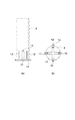
まず、本実施形態の洗浄方法の説明に先立ち、当該洗浄方法を実施するための洗浄装置について説明する。図1は、本発明に係る電子写真感光体用基体の洗浄方法を実施するための洗浄装置の一例を示す概略図、図2(a)は、図1の洗浄装置に用いる基体保持部の側面図、図2(b)は、図1の洗浄装置に用いる基体保持部の平面図である。
【0023】
図1に示すように、洗浄装置1は、洗浄液2を収容する洗浄槽3を備えており、洗浄槽3の上部には開口が形成されている。また洗浄槽3には洗浄液供給手段(図示せず)により洗浄槽3底面の中央部から洗浄液が供給されるようになっている。更に洗浄槽3上部の外周には、洗浄槽3からオーバーフローした洗浄液2を受容するオーバーフローパン15が設けられている。オーバーフローパン15で受容された洗浄液は、その再利用のため、洗浄液貯留タンク(図示せず)に導入されるようになっている。また洗浄槽3の底部には、超音波振動子16が設けられている。この超音波振動子16は、基体4に付着した異物を基体4の表面から容易に剥離させるためのものである。
【0024】
また洗浄装置1は、電子写真感光体用基体4を昇降させる昇降装置5を備えている。昇降装置5は、電子写真感光体用基体4を洗浄槽3の洗浄液2中に浸漬し、洗浄液2から引き上げるためのものである。昇降装置5は、モータ7を有し、モータ7の回転軸には鉛直方向に延びる駆動軸8が連結されている。また駆動軸8には、昇降部材9が駆動軸8の回転に連動して昇降するように取り付けられている。図2(b)に示すように、昇降部材9は、基体4を保持するための十字型の基体保持部10を備えており、基体保持部10は、支持部13を介して駆動軸8に取付けられている。十字形の基体保持部10の上面は、基体4を載せる受け面11となっており、受け面11からは、基体4を受け面11上の所定位置に位置決めするための4本の位置決めピン12が上方に延びている。この受け面11及び4本の位置決めピン12により基体4が保持される(図2(a)参照)。
【0025】
図1に戻って、昇降部材9の支持部13には、基体4を上下に揺動させる低周波振動装置14が設置されている。低周波振動装置14は、基体4の表面に付着した異物を効率よく除去するためのものである。なお、低周波振動装置14は、昇降部材9の支持部13に限らず、基体保持部10に設置されてもよい。この場合でも、基体4に低周波振動を与えることができる。
【0026】
(電子写真感光体用基体の洗浄方法)
次に、上記洗浄装置1を用いた電子写真感光体用基体の洗浄方法について説明する。
【0027】
まず、脱脂用洗浄液を用いて電子写真感光体用基体4の脱脂洗浄を行う(脱脂洗浄工程)。脱脂用洗浄液は、基体4の脱脂洗浄が可能であれば特に限定されず、このような脱脂用洗浄液としては、例えば水に界面活性剤を混合させたものが挙げられる。
こうして基体4について脱脂洗浄を行うと、基体4の表面には通常、油分や異物が残留している。 このため、基体4の表面に残留している油分や異物を除去するため、脱脂洗浄された基体4に対してすすぎ洗浄を行う(すすぎ洗浄工程)。
【0028】
基体4のすすぎ洗浄は、上記洗浄装置1を用いて行う。この場合、洗浄槽3には、洗浄液供給手段により洗浄液2を供給し、洗浄槽3の上部開口から洗浄液をオーバーフローさせる。ここで用いる洗浄液は、基体4のすすぎ洗浄が可能なものであれば特に限定されず、このような洗浄液としては、例えば井戸水や水道水を使用することができるが、井戸水の場合、井戸水中の藻類や細菌の増殖による水垢により異物欠陥が発生する場合があり、水道水の場合は、水道水中の塩素成分により基体4が腐蝕する場合があるため、このような異物欠陥や基体4の腐蝕を防止する観点からは、除菌されたイオン交換水や蒸留水等の純水を用いることが好ましい。ここで、純水の電気伝導度は1μS/cm以下に設定することが好ましい。純水の電気伝導度が1μS/cmを超えると、水によるシミや鉄サビ等の付着による塗膜欠陥が発生する傾向がある。また、水温は20〜60℃にすることが、洗浄性及び基体4の腐蝕防止の点で効果的である。
【0029】
一方、電子写真感光体用基体4を、昇降部材9の基体保持部10で保持する。具体的には、基体4の内側に位置決めピンが挿入されるように基体4を基体保持部10上に配置する。これにより、基体4の下端面が基体保持部10の受け面11と接触し、基体4が基体保持部10に保持される。
【0030】
次に、モータ7を作動して駆動軸8を回転させる。そして、駆動軸8の回転に連動して昇降部材9を下降させることによって基体4を下降させ、基体4を洗浄槽3の洗浄液2中に浸漬させる(図3(a)参照)。浸漬は、基体4の上端が洗浄液2の液面付近に達するまで行い、基体4が洗浄液2中に完全に浸漬した状態でモータ7を停止し基体4を静止させる。このとき、洗浄液2により、基体4に付着した異物が基体4の表面から剥離され、洗浄液2中を浮遊するようになる。なお、基体4の下降速度、すなわち浸漬速度は任意である。
【0031】
基体4を洗浄槽3中に所定時間停止させた後、再びモータ7を作動して駆動軸8を逆回転させる。そして、駆動軸8の逆回転に連動して昇降部材9を上昇させ、基体4を洗浄槽3の洗浄液2から引き上げる(図3(b)参照)。基体4の引き上げは、基体4が洗浄液2の液面から完全に露出されるまで行う。
【0032】
このとき、基体4の引き上げ速度は、10mm/s以上とする。この範囲の速度で基体4を液面から引き上げると、洗浄液2の表面付近に存在している異物が基体4に付着しにくくなる。逆に、10mm/s未満では、引き上げた基体4の表面に洗浄液2中の異物が付着する現象が顕著となる。
【0033】
引き上げ速度は、生産性を向上させる観点からは、20mm/s以上であることがより好ましい。また引き上げ速度は、400mm/s以下であることが好ましい。引き上げ速度が400mm/sを超えると液面から基体下端部を引き上げる際の洗浄液2の飛び散りが激しくなり、他の基体4や洗浄装置1を汚染する原因となる傾向がある。
【0034】
基体4を引き上げる動作が完了したら、上記と同様の手順で、再度、基体4を洗浄槽3に浸漬させる動作及び引き上げの動作を行う。
【0035】
こうして浸漬と引き上げという一連の動作を複数回繰り返す。繰り返すときの浸漬及び引き上げの条件は上記と同様である。こうして最終的に、電子写真感光体用基体4の表面における清浄度の十分高い基体4を得ることができる。
【0036】
なお、浸漬と引き上げの動作の繰り返し回数は基体4の汚れの付着度合いにより決定されるが、一つの洗浄槽3に対して浸漬と引き上げの動作を3回以上繰り返すと基体4の表面における清浄度がより高くなる。
【0037】
こうして基体4のすすぎ洗浄が終了した後、基体4を温純水槽に浸漬して引き上げることで水切りを行い、基体4に付着する純水の量を十分に低下させる。この場合、基体4の表面に水滴が残留しにくく、水シミが発生しにくくなる。温純水の温度は通常は40〜70℃であり、好ましくは45〜60℃である。こうして基体4の洗浄が完了する。
【0038】
上記基体4のすすぎ洗浄は、洗浄槽3の周囲の環境をクリーン度をクラス1000以下の環境にして行うことが好ましい。クリーン度がクラス1000を超えると、基体4の引き上げ時に空気中の塵埃が基体4に付着し、高い清浄度が得られなくなる傾向がある。洗浄槽3の周囲の環境をクラス1000以下のクリーン度にするためには、洗浄装置1をクリーンルームに収容するようにすればよい。なお、クリーン度のクラスは、100以下であることがより好ましい。この場合、基体4の清浄度がより高くなる。
【0039】
なお、基体4のすすぎ洗浄に際しては、上記浸漬と引き上げの一連の動作を複数回繰り返し行っている間は、洗浄液2が洗浄槽3からオーバーフローした状態を保つことが好ましい。基体4に付着している異物は、基体4の洗浄液2への浸漬により基体4の表面から剥離されて洗浄液2の液面付近を浮遊するため、洗浄液2がオーバーフローされることで、洗浄液2と共に異物が洗浄槽3内から排出される。従って、基体4の引き上げ時における基体4への異物の再付着をより十分に防止することができる。
【0040】
また、基体4のすすぎ洗浄に際しては、基体4が洗浄液2中に浸漬されている間、基体4に対し、超音波振動子7により20〜100kHzの間の発振周波数で超音波を照射することが好ましい。これにより、基体4の付着物が基体4の表面から容易に剥離される。超音波は上記の通り少なくとも基体4が浸漬しているときに照射しているが、基体4が洗浄槽3から引き上げられているときは照射を停止してもかまわない。上記発振周波数は20〜100kHzの間で、異物の付着度合いにより任意に選択される。
【0041】
さらに、基体4のすすぎ洗浄に際しては、基体4が洗浄槽3中に浸漬され、超音波を照射されている間、超音波の定在波の発生により基体4の表面に作用するキャビテーションのむらができる傾向がある。この場合、洗浄度合いにむらができたり、定在波の強いところでは、基体表面に微小な穴があいたりすることがある。そこで、基体4を洗浄液2中に浸漬し、基体4に超音波を照射する場合は、キャビテーションのむらを防止する目的で、基体4を洗浄液2中で上下に揺動することが好ましい。
【0042】
基体4を洗浄槽3に浸漬した状態で、超音波照射すると、基体4から剥離された異物が基体4の表面近傍に浮遊する。このままの状態では、基体4の引き上げ時に、一度剥離された異物が基体4の表面に再度付着し、洗浄品質が向上しないおそれがある。これを解消するのに、基体4を洗浄液2中に浸漬し、基体4に超音波を照射している場合には、基体4に対して1〜100Hzの低周波振動を与えることが有効である。洗浄液2中で基体4に上記低周波振動を与えると、一度基体4から剥離された異物が基体4から離れる方向へ移動するため、基体4の引き上げ時に異物が再付着する確率が低下する。なお、低周波振動の周波数が上記周波数の範囲より低い又は高い場合は、基体4の浸漬時において超音波照射により基体4表面から剥離した異物が基体4の表面近傍にとどまり、基体4の引き上げ時における異物の基体4への再付着を十分に防止できなくなる傾向がある。
【0043】
基体4を洗浄液2から引き上げた後であって洗浄液2に浸漬させる前においては、洗浄槽3の開口縁部の内側中心部に浮き上がってきた異物は、洗浄槽3の開口縁部まで移動した後、オーバーフローパン6へ排出されるため、中心部以外の箇所に浮き上がってきた異物と比較して液面を移動する時間が長く、液面に滞留しがちである。そこで、この現象を軽減し、洗浄槽3の開放縁部の中心部に浮き上がってきた異物を速やかにオーバーフローさせるために、基体4を洗浄液2から引き上げた後であって洗浄液2に浸漬させる前において、洗浄液2の液面に斜め上方からクリーンエアーを吹き付けることが好ましい。
【0044】
この場合、上記クリーンエアーの吹き付けは、例えば図4に示すように、洗浄槽3の液面近傍に設置されたエアーノズル21を用いて実施できる。この場合、クリーンエアーとしてはクリーン度クラス1000以下、さらに好ましくはクリーン度100以下のものを用いる。またエアー吹き付けの突出圧、流量などは、用いるエアーノズル21、エアーノズル21先端から液面までの距離、洗浄槽3の開口縁部の形状、大きさなどにより任意に選択されるが、液面を波立たせないように設定されることが好ましい。エアーノズル21により洗浄液2の液面に斜め上方からクリーンエアーを吹き付けることにより、液面における異物22を有効に開口縁部に移動させることができる。液面とエアーノズル21とのなす角度は、0度より大きく60度以下の範囲であることが好ましい。この場合、異物の移動が効果的に促進される。
【0045】
上記のエアーの吹付けは、基体4を洗浄液2に浸漬するために下降させている間と、洗浄液2から引き上げるために上昇させている間は停止し、基体4が洗浄液2中に完全に浸漬されている間と、洗浄液2から完全に引き上げられた後に吹き付けると、異物の移動が効果的に行われ、またランニングコストを低減することもできる。
【0046】
基体4はその下端部を基体保持部12により保持した状態で、浸漬および引き上げの動作が行われる。このとき、図5(a)、(b)に示すように、基体4の内周面と基体保持部10の受け面11との間に形成される間隙部の断面積S1と、基体4の開口部全体の断面積S0との比率S1/S0が0.3以上となることが効果的である。上記比率が0.3より小さいと、洗浄液2に浸漬する際、基体4内部に洗浄液2が流通しにくくなり、基体4の内面に付着している異物の排出が困難になる傾向がある。内面に付着した異物が適切に外部に排出されないと、その異物が洗浄槽3内で再度基体4に付着する確率が高くなるため、洗浄品質を落とすことになる。なお、基体保持部10の形状は、上記比率が0.3以上となる限り、任意であり、図2(b)に示すような十字形に限定されない。
【0047】
本発明に係る基体の洗浄方法は、上記実施形態に限定されるものではない。例えば上記実施形態では、基体4をすすぎ洗浄する場合にのみ、洗浄槽3で洗浄液2をオーバーフローさせた状態で、洗浄液2に基体4を浸漬した後、引き上げ速度10mm/s以上で洗浄液2から完全に引き上げる動作を複数回繰り返しているが、基体4をすすぎ洗浄する場合のみならず脱脂洗浄する場合にも上記動作を複数回繰り返して構わない。この場合、基体4が洗浄槽の洗浄液に浸漬されている間、基体4に20〜100kHzの超音波を照射すること、洗浄槽3の周囲の環境をクリーン度クラス1000以下の環境にすること、基体4が洗浄槽の洗浄液に浸漬されている間、基体4に1〜100Hzの低周波振動を与えること、洗浄液の液面に斜め上方からクリーンエアーを吹き付けてから基体4を洗浄槽に浸漬することが好ましいのは、上記実施形態と同様である。
【0048】
(電子写真感光体の製造方法)
次に、本発明の電子写真感光体の製造方法について説明する。
【0049】
まず、電子写真感光体用基体4を用意する。
【0050】
この基体4に対しては通常、鏡面切削する。鏡面切削は一般に、以下のようにして行われる。先ず精密切削用の旋盤にダイヤモンドバイトをセットし、旋盤の回転フランジに、予め荒切削された基体4を固定する。そして、旋盤により基体4を回転させ、これに潤滑油として灯油を噴霧しながらバイトを当て、鏡面切削を施す。従って、基体4に対して鏡面切削を行うと、基体4の表面には、灯油による油分やアルミニウムの切粉が付着することがある。
【0051】
この基体4について、上述した洗浄方法により洗浄を行う。これにより、表面において十分に高い清浄度をもつ基体4が得られる。
【0052】
なお、基体4の洗浄に先立って、基体4に粗面化処理(非鏡面処理、凹凸形成処理)がなされてもよい。これにより、電子写真感光体において、露光を行う時に、基体4の表面において光が散乱され、干渉縞の発生が十分に防止される。
【0053】
こうして洗浄された基体4は、当該基体4に付着した水分を除去する為に乾燥機に入れられ、温風乾燥される。これにより、基体4の表面に残留した水滴による基体4上でのシミの発生が防止され、得られる電子写真感光体を用いた画像形成装置において画質欠陥の発生を十分に防止できる。
【0054】
乾燥後の基体4は室温まで冷却される。
【0055】
次に、この基体4の表面に、下引層形成用塗布液を塗布し、乾燥させる。これにより下引層が得られる。このとき、基体4の表面においては、ハジキ、シミ等の塗布欠陥の原因となる異物等の付着量が十分に低減されている。従って、下引き層形成用塗布液を塗布する際にハジキ、シミ等の塗布欠陥の発生を十分に防止できる。
【0056】
その後、下引層の上に電荷発生層形成用塗布液が塗布、乾燥され、これにより電荷発生層が得られる。最後に、電荷発生層の上に電荷輸送層形成用塗布液が塗布、乾燥され、これにより電荷輸送層が得られる。
【0057】
上記塗布液の塗布方法としては、浸漬塗布法、スプレー塗布法、フローコート塗布法等の様々な塗布方法があるが、塗布方法は、塗布液の特性に応じて任意に選択することができる。また、通常は1層塗布する毎に塗布液を乾燥させる必要があるが、塗布液の種類により強制乾燥が不要なものもあるため、必ずしも乾燥機を使用する必要はない。更に下引き層、電荷発生層及び電荷輸送層は、本明細書においてはいずれも感光層とする。
【0058】
こうして基体4の上に感光層が形成され、電子写真感光体の製造が終了する。この電子写真感光体においては、上述したように塗布欠陥の発生が十分に防止される。このため、電子写真感光体を画像形成装置に装着して画像を形成しても、画像において黒ポチ、白ポチの発生、ハーフトーン画像のムラ等が防止され、画像品質への悪影響を十分に防止することができる。
【0059】
なお、上記電子写真感光体の製造方法の実施形態においては、下引き層が用いられているが、下引き層は必ずしも必要ではない。また、電荷発生層及び電荷輸送層の積層位置は逆であってもよい。即ち電荷輸送層の上に電荷発生層が形成されていてもよい。
【0060】
以下、本発明の内容を、実施例を用いてより具体的に説明するが、本発明はこれらの実施例に何ら限定されるものではない。
【0061】
【実施例】
(実施例1)
ダイヤモンドバイトを用いた鏡面旋盤により、外径84mm、長さ340mm、厚さ1mmの円筒状アルミニウム基体に対して鏡面切削加工を行い、基体表面を表面粗さRa(JIS B0601に規定されている中心線平均粗さ)が0.04ミクロンの平滑面に仕上げた。
【0062】
鏡面切削加工終了後、基体の脱脂洗浄を以下の手順で行った。即ち脱脂洗浄は、クリーン度のクラスが1000のクリーンルーム内に、図1のような構成を持つ洗浄装置1を2台収容し、これら2台の洗浄装置1を用いて、2つの洗浄槽において順次基体4の脱脂洗浄を行った。各洗浄槽3には、底部より、界面活性剤をイオン交換水に溶解させた洗浄液2を供給し、上部から洗浄液2をオーバーフローさせた。界面活性剤としては、非イオン性界面活性剤(ライオン(株)製LH?600F)を用い、洗浄液2中の界面活性剤の濃度は、1つ目の洗浄槽3では10〜20質量%とし、2つ目の洗浄槽3では1〜2質量%とした。また、洗浄液2のイオン交換水としては、電気伝導度が0.1μS/cm以下のものを使用した。更に基体には、超音波振動子16により洗浄液2を介して40kHzの超音波を印加した。
【0063】
脱脂洗浄時には、昇降装置5を用いて、基体4を洗浄液2に浸漬した後、洗浄液2から上方に完全に引き上げる動作を各洗浄槽3において3回繰り返した。基体4を上方に引き上げるときの速度は15mm/sとした。
【0064】
このようにして基体4の脱脂洗浄を行った後、基体4のすすぎ洗浄を行った。すすぎ洗浄は、洗浄液2としてイオン交換水のみを用いた以外は脱脂洗浄と全く同様にして行った。
【0065】
また、脱脂洗浄及びすすぎ洗浄時に基体を洗浄液中に浸漬している間、各洗浄装置1に含まれるバイブレータ14により基体に50Hzの低周波振動を与えた。
【0066】
すすぎ洗浄を行った後は、基体を35℃に保持した温純水中に50秒間浸漬した後、5mm/sの速さで引き上げ、最終洗浄槽で液温50℃の洗浄液中に基体を20秒浸漬した後、5mm/sの速度で引き上げて水切り洗浄した。
【0067】
最後に、洗浄した基体を乾燥室に入れることにより、135度の熱風乾燥を90秒行った。
【0068】
(実施例2)
実施例1において、脱脂洗浄及びすすぎ洗浄時に、基体を上方に引き上げるときの引き上げ速度を150mm/sとしたこと以外は実施例1と全く同様にして、基体の鏡面切削加工、基体の洗浄及び基体の熱風乾燥を順次実施した。
【0069】
(実施例3)
実施例1において、脱脂洗浄及びすすぎ洗浄時に、基体を洗浄液中に浸漬している間に基体に与える低周波振動の周波数を10Hzとしたこと以外は実施例1と全く同様にして、基体の鏡面切削加工、基体の洗浄及び基体の熱風乾燥を順次実施した。
【0070】
(実施例4)
実施例1において、脱脂洗浄及びすすぎ洗浄時に、基体を洗浄液中に浸漬している間に基体に与える低周波振動の周波数を3Hzとしたこと以外は実施例1と全く同様にして基体の鏡面切削加工、基体の洗浄及び基体の熱風乾燥を順次実施した。
【0071】
(実施例5)
洗浄装置1において、内径10mmの1本のエアーノズルを、エアーノズルの中心軸線が液面に対して約30°となるように固定した。実施例1において、脱脂洗浄とすすぎ洗浄時で、基体を洗浄液に浸漬する直前に、これらのエアーノズルにより洗浄液2の液面に斜め上方からクリーン度のクラス100のクリーンエアーを吹き付け、その後に基体を洗浄液に浸漬する動作を繰り返すようにして洗浄したこと以外は実施例1と全く同様にして基体の鏡面切削加工、基体の洗浄及び基体の熱風乾燥を順次実施した。なお、クリーンエアーを液面に吹き付けたときのクリーンエアーの流量は、120×10−6m3/s、吹付け時間は10秒とした。
【0072】
(実施例6)
ダイヤモンドバイトを用いた鏡面旋盤により、外径30mm、長さ334mm、厚さ1mmの円筒状アルミニウム基体に鏡面切削加工を行い、表面粗さRa(JIS B0601に規定されている中心線平均粗さ)が0.04ミクロンの平滑面に仕上げた。
【0073】
以降、実施例1と同様にして、基体の洗浄及び基体の熱風乾燥を順次実施した。
【0074】
(実施例7)
実施例1において、脱脂洗浄及びすすぎ洗浄時に、基体を洗浄液中に浸漬している間に基体に与える低周波振動の周波数を0.5Hzとしたこと以外は実施例1全く同様にして基体の鏡面切削加工、基体の洗浄及び基体の熱風乾燥を順次実施した。
【0075】
(実施例8)
実施例1において、脱脂洗浄及びすすぎ洗浄時に、基体を洗浄液中に浸漬している間に基体に与える低周波振動の周波数を200Hzとしたこと以外は実施例1と全く同様にして基体の鏡面切削加工、基体の洗浄及び基体の熱風乾燥を順次実施した。
【0076】
(実施例9)
実施例1において、脱脂洗浄及びすすぎ洗浄時に、基体を洗浄液中に浸漬している間、基体に低周波振動を与えないこと以外は実施例1と全く同様にして基体の鏡面切削加工、基体の洗浄及び基体の熱風乾燥を順次実施した。
【0077】
(比較例1)
実施例1において、脱脂洗浄およびすすぎ洗浄時に、基体をそれぞれの洗浄槽3において60秒間浸漬した後に速度5mm/sで引き上げる動作を1回ずつ行うようにして洗浄したこと以外は実施例1と同様にして基体の鏡面切削加工、基体の洗浄及び基体の熱風乾燥を順次実施した。
【0078】
(比較例2)
実施例1において、脱脂洗浄およびすすぎ洗浄時に、基体を洗浄液から上方に引き上げるときの速度を7mm/sとしたこと以外は実施例1と全く同様にして基体の鏡面切削加工、基体の洗浄及び基体の熱風乾燥を順次実施した。
【0079】
(比較例3)
実施例1において、脱脂洗浄及びすすぎ洗浄時の洗浄液2のオーバーフローを停止した状態で洗浄したこと以外は実施例1と全く同様にして基体の鏡面切削加工、基体の洗浄及び基体の熱風乾燥を順次実施した。
【0080】
(欠陥発生率の評価)
実施例1〜9及び比較例1〜3により得られた電子写真感光体用基体各々1000本について、CCDカメラと顕微鏡とからなる表面欠陥評価装置を用いて、基体表面における異物の有無を確認し、欠陥発生率を算出した。欠陥発生率は、異物の有無を確認した基体の本数に占める最大長が20μm以上の異物が1つでも認められた基体の割合から算出した。その結果を表1に示す。
【0081】
【表1】

【発明の効果】
以上説明したように本発明の電子写真感光体用基体の洗浄方法によれば、表面における清浄度の十分に高い電子写真感光体用基体を得ることができる。
【0083】
更に本発明の電子写真感光体の製造方法によれば、基体洗浄工程により表面における清浄度の十分に高い基体が得られるため、基体表面上に感光層を形成して電子写真感光体を製造しても、黒ポチ、白ポチ、ハーフトーン画像のムラ等の発生や一様帯電時の漏電を十分に防止することができ、極めて高品質な電子写真感光体を得ることができる。
【図面の簡単な説明】
【図1】本発明に係る電子写真感光体用基体の洗浄方法を実施するための洗浄装置の一例を示す概略図である。
【図2】(a)は図1の基体保持部の側面図、(b)は図1の基体保持部の平面図である。
【図3】(a)は電子写真感光体基体の浸漬時の状態を示す概略図、(b)は電子写真感光体基体の引き上げ時の状態を示す概略図である。
【図4】クリーンエアーを液面に吹き付ける時の状態を示す概略図である。
【図5】(a)は、基体の平面図、(b)は、基体保持部の平面図である。
【符号の説明】
4…電子写真感光体用基体、3…洗浄槽、2…洗浄液。[0001]
TECHNICAL FIELD OF THE INVENTION
The present invention relates to a method for cleaning a substrate for an electrophotographic photosensitive member on which a photosensitive layer is formed in the electrophotographic photosensitive member, and a method for manufacturing the electrophotographic photosensitive member.
[0002]
[Prior art]
A processing oil, a lubricating oil, a rust-preventive oil, or the like is used for a substrate for an electrophotographic photoreceptor (hereinafter, referred to as a substrate as necessary) during processing. For this reason, oil remains on the substrate after processing, and in addition, cutting powder, dust in the air, and foreign matter derived from humans during handling adhere to the substrate. Must be used.
[0003]
As a method of cleaning a substrate, there is a method of cleaning with a solvent, a semi-aqueous cleaning agent, a water-based cleaning agent, or pure water. At present, however, environmental problems such as ozone layer depletion, global warming, air pollution, and human body. In consideration of the adverse effects on water and the like, chlorine-based solvents have been reduced and completely abolished, and cleaning methods using aqueous cleaning agents or pure water have been implemented.
[0004]
When cleaning with an aqueous cleaning agent or pure water, first, the substrate is immersed in a cleaning solution containing a surfactant to remove deposits such as oil and foreign substances, and then the water in the rinsing tank is rinsed. The cleaning liquid is washed away by successive immersion, and finally the water remaining on the substrate is dried to complete the cleaning.
[0005]
However, it is difficult to obtain sufficient cleaning power simply by immersing the substrate in the cleaning liquid. Therefore, in order to enhance the cleaning power, ultrasonic cleaning using the cavitation effect, high-pressure injection of the cleaning liquid using a jet nozzle, brushes and blades, etc. And various cleaning methods such as rubbing cleaning (for example, see Patent Document 1).
[0006]
[Patent Document 1]
JP-A-5-61215
[0007]
[Problems to be solved by the invention]
However, none of the above-described cleaning methods can reliably remove both oil and foreign matter adhering to the substrate. As a result, if oil remains on the surface of the substrate, the coating solution is repelled at the time of application of the coating solution for forming a photosensitive layer, resulting in unevenness. In such a case, there is a problem that a leakage starts at the time of charging, and the image quality is deteriorated in any case.
[0008]
SUMMARY OF THE INVENTION The present invention has been made to solve the above problems, and an electrophotographic photosensitive member capable of obtaining a substrate for an electrophotographic photosensitive member that is effective for both degreasing and foreign matter removal and has sufficiently high surface cleanliness. An object of the present invention is to provide a method for cleaning a body substrate and a method for manufacturing an electrophotographic photoreceptor.
[0009]
[Means for Solving the Problems]
In order to solve the above problems, the present invention provides a degreasing cleaning step of performing degreasing cleaning of an electrophotographic photoreceptor substrate, and a rinsing step of rinsing the electrophotographic photoreceptor substrate cleaned in the degreasing cleaning step in a cleaning tank. A washing step of rinsing the electrophotographic photoreceptor substrate in the cleaning solution in a state where the cleaning solution overflows in the cleaning tank in the rinsing step, The operation of completely removing the substrate from the cleaning liquid at a speed of 10 mm / s or more is repeated a plurality of times to perform rinsing cleaning of the electrophotographic photosensitive member substrate.
[0010]
According to the method for cleaning a substrate for an electrophotographic photosensitive member of the present invention, first, the substrate for an electrophotographic photosensitive member is degreased and cleaned. At this time, oil and foreign matters usually remain on the surface of the electrophotographic photosensitive member substrate. Therefore, when the substrate for electrophotographic photosensitive member is immersed in the cleaning solution in a state where the cleaning solution overflows from the cleaning tank, oil and foreign matters remaining on the surface of the substrate for electrophotographic photosensitive member are separated from the surface of the substrate by the cleaning solution. Then, the electrophotographic photoreceptor substrate is pulled up from the cleaning liquid at a pulling speed of 10 mm / s or more, thereby sufficiently preventing foreign substances present near the liquid level from re-adhering to the electrophotographic photoreceptor substrate surface. Can be. Then, a series of such immersion and lifting operations are repeated a plurality of times, whereby a substrate having sufficiently high surface cleanliness can be obtained.
[0011]
In the above-mentioned rinsing step, it is preferable that the electrophotographic photosensitive member substrate is irradiated with ultrasonic waves of 20 to 100 kHz while the electrophotographic photosensitive member substrate is immersed in the cleaning solution in the cleaning tank.
[0012]
By irradiating an ultrasonic wave in the above frequency range while the substrate for electrophotographic photosensitive member is immersed in the cleaning liquid, the foreign matter adhering to the substrate for electrophotographic photosensitive member is easily peeled off from the substrate.
[0013]
In the rinsing step, it is preferable that the environment around the cleaning tank be an environment having a cleanliness class of 1000 or less.
[0014]
By setting the cleanliness class around the cleaning tank within the above range, adhesion of foreign substances such as dust in the air to the electrophotographic photosensitive member substrate can be sufficiently reduced when the substrate is lifted from the cleaning tank.
[0015]
In the rinsing step, it is preferable to apply a low-frequency vibration of 1 to 100 Hz to the electrophotographic photoconductor substrate while the electrophotographic photoconductor substrate is immersed in the cleaning solution in the cleaning tank.
[0016]
By applying low-frequency vibration in the above-mentioned frequency range to the electrophotographic photoconductor substrate while the electrophotographic photoconductor substrate is immersed in the cleaning liquid, foreign matter separated from the electrophotographic photoconductor substrate is It moves in a direction away from the electrophotographic photosensitive member substrate. Therefore, when the electrophotographic photoreceptor substrate is pulled up from the cleaning liquid, reattachment of foreign matter to the electrophotographic photoreceptor substrate is sufficiently prevented.
[0017]
Further, it is preferable that clean air is blown from obliquely above the liquid surface of the cleaning liquid, and then the electrophotographic photosensitive member substrate is immersed in the cleaning liquid in the cleaning tank.
[0018]
By blowing clean air on the surface of the cleaning liquid, foreign substances floating on the surface of the cleaning liquid can be effectively moved to the edge of the cleaning tank. As a result, the foreign matter easily overflows from the edge of the cleaning tank together with the cleaning liquid, and the residence time of the foreign substance on the liquid surface can be further reduced.
[0019]
The method for manufacturing an electrophotographic photoreceptor of the present invention includes a substrate cleaning step of cleaning a substrate for an electrophotographic photoreceptor, and a photosensitive layer forming step of forming a photosensitive layer on the electrophotographic photoreceptor substrate washed in the substrate cleaning step. Wherein the substrate cleaning step is performed by the above-described method for cleaning a substrate for an electrophotographic photosensitive member.
[0020]
According to this manufacturing method, when the substrate cleaning step is performed by the cleaning method, the cleanliness on the surface of the substrate for an electrophotographic photosensitive member can be sufficiently increased. For this reason, when a photosensitive layer is formed on a substrate for an electrophotographic photosensitive member to form an electrophotographic photosensitive member, and an image is formed using the obtained electrophotographic photosensitive member, the image has black spots and white dots. It is possible to sufficiently prevent the occurrence of spots, unevenness in a halftone image, and the like, and leakage during uniform charging.
[0021]
BEST MODE FOR CARRYING OUT THE INVENTION
Hereinafter, embodiments of the present invention will be described in detail.
[0022]
(Cleaning device)
First, prior to description of the cleaning method of the present embodiment, a cleaning apparatus for performing the cleaning method will be described. FIG. 1 is a schematic view showing an example of a cleaning apparatus for carrying out a method for cleaning a substrate for an electrophotographic photosensitive member according to the present invention. FIG. 2A is a side view of a substrate holder used in the cleaning apparatus of FIG. FIG. 2B is a plan view of a base holder used in the cleaning apparatus of FIG.
[0023]
As shown in FIG. 1, the
[0024]
Further, the
[0025]
Returning to FIG. 1, a low-
[0026]
(Method of Cleaning Electrophotographic Photoreceptor Substrate)
Next, a method for cleaning the electrophotographic photosensitive member substrate using the
[0027]
First, the substrate 4 for an electrophotographic photosensitive member is degreased and washed using a degreasing cleaning solution (degreasing cleaning step). The cleaning liquid for degreasing is not particularly limited as long as the cleaning of the substrate 4 can be performed, and such a cleaning liquid for degreasing includes, for example, a mixture of water and a surfactant.
When the base 4 is thus degreased and washed, oil and foreign matters usually remain on the surface of the base 4. Therefore, in order to remove oil and foreign matter remaining on the surface of the base 4, the degreased base 4 is rinsed (rinse cleaning step).
[0028]
The rinsing of the base 4 is performed using the above-described
[0029]
On the other hand, the substrate 4 for an electrophotographic photosensitive member is held by the
[0030]
Next, the
[0031]
After stopping the base 4 in the cleaning tank 3 for a predetermined time, the
[0032]
At this time, the lifting speed of the base 4 is set to 10 mm / s or more. When the substrate 4 is pulled up from the liquid surface at a speed in this range, foreign substances existing near the surface of the cleaning
[0033]
The lifting speed is more preferably 20 mm / s or more from the viewpoint of improving productivity. Further, the lifting speed is preferably 400 mm / s or less. If the lifting speed exceeds 400 mm / s, the cleaning
[0034]
When the operation of lifting the base 4 is completed, the operation of dipping the base 4 in the cleaning tank 3 and the operation of lifting are performed again in the same procedure as described above.
[0035]
In this way, a series of operations of dipping and lifting are repeated a plurality of times. The conditions of immersion and lifting when repeating are the same as described above. Thus, finally, the substrate 4 having sufficiently high cleanliness on the surface of the substrate 4 for an electrophotographic photosensitive member can be obtained.
[0036]
The number of repetitions of the immersion and lifting operations is determined by the degree of contamination of the substrate 4, but if the immersion and lifting operations are repeated three times or more in one cleaning tank 3, the cleanliness on the surface of the substrate 4 is increased. Is higher.
[0037]
After the rinsing of the substrate 4 is completed, the substrate 4 is immersed in a hot pure water bath and pulled up to drain the water, and the amount of pure water adhering to the substrate 4 is sufficiently reduced. In this case, water droplets hardly remain on the surface of the base 4 and water stains are hardly generated. The temperature of the hot pure water is usually 40 to 70 ° C, preferably 45 to 60 ° C. Thus, the cleaning of the base 4 is completed.
[0038]
It is preferable that the rinsing of the base 4 is performed by setting the environment around the cleaning tank 3 to an environment having a cleanness of class 1000 or less. If the cleanliness exceeds the class 1000, dust in the air adheres to the base 4 when the base 4 is pulled up, and high cleanliness tends not to be obtained. In order to make the environment around the cleaning tank 3 cleanliness of class 1000 or less, the
[0039]
During the rinsing of the base 4, it is preferable to keep the state in which the
[0040]
In rinsing the base 4, it is possible to irradiate the base 4 with ultrasonic waves at an oscillation frequency of 20 to 100 kHz by the
[0041]
Further, when the substrate 4 is rinsed and washed, the substrate 4 is immersed in the cleaning tank 3 and, while being irradiated with ultrasonic waves, uneven cavitation acting on the surface of the substrate 4 due to generation of standing waves of ultrasonic waves is generated. Tend. In this case, the degree of cleaning may be uneven, or a fine hole may be formed in the surface of the base in a place where the standing wave is strong. Therefore, when immersing the substrate 4 in the cleaning
[0042]
When the substrate 4 is immersed in the cleaning tank 3 and irradiated with ultrasonic waves, the foreign matter separated from the substrate 4 floats near the surface of the substrate 4. In this state, when the substrate 4 is pulled up, the foreign matter that has been peeled off once again adheres to the surface of the substrate 4, and the cleaning quality may not be improved. In order to solve this, it is effective to apply low frequency vibration of 1 to 100 Hz to the base 4 when the base 4 is immersed in the cleaning
[0043]
After the substrate 4 has been pulled up from the cleaning
[0044]
In this case, the clean air can be sprayed using an
[0045]
The blowing of the air is stopped while the base 4 is lowered to be immersed in the cleaning
[0046]
The base 4 is immersed and pulled up with its lower end held by the
[0047]
The method for cleaning a substrate according to the present invention is not limited to the above embodiment. For example, in the above embodiment, only when the substrate 4 is rinsed and washed, the substrate 4 is immersed in the
[0048]
(Method of manufacturing electrophotographic photoreceptor)
Next, a method for manufacturing the electrophotographic photoreceptor of the present invention will be described.
[0049]
First, an electrophotographic photosensitive member base 4 is prepared.
[0050]
This substrate 4 is usually mirror-cut. Mirror finishing is generally performed as follows. First, a diamond cutting tool is set on a lathe for precision cutting, and the substrate 4 that has been roughly cut in advance is fixed to a rotating flange of the lathe. Then, the base body 4 is rotated by a lathe, and a tool is applied to the base body 4 while spraying kerosene as a lubricating oil to perform mirror-surface cutting. Therefore, when mirror-cutting is performed on the base 4, the oil content of kerosene or aluminum chips may adhere to the surface of the base 4.
[0051]
The substrate 4 is cleaned by the above-described cleaning method. Thereby, the substrate 4 having sufficiently high cleanliness on the surface is obtained.
[0052]
Prior to the cleaning of the substrate 4, the substrate 4 may be subjected to a surface roughening process (non-mirror surface treatment, unevenness forming process). Accordingly, when the electrophotographic photosensitive member is exposed, light is scattered on the surface of the substrate 4 and the occurrence of interference fringes is sufficiently prevented.
[0053]
The substrate 4 thus washed is put into a drier to remove moisture adhering to the substrate 4, and dried with hot air. As a result, the occurrence of spots on the substrate 4 due to water droplets remaining on the surface of the substrate 4 can be prevented, and the occurrence of image quality defects in an image forming apparatus using the obtained electrophotographic photosensitive member can be sufficiently prevented.
[0054]
The dried substrate 4 is cooled to room temperature.
[0055]
Next, a coating liquid for forming an undercoat layer is applied to the surface of the substrate 4 and dried. Thereby, an undercoat layer is obtained. At this time, on the surface of the base 4, the amount of foreign matter or the like that causes coating defects such as cissing and spots is sufficiently reduced. Therefore, it is possible to sufficiently prevent the occurrence of coating defects such as repelling and spots when applying the coating liquid for forming the undercoat layer.
[0056]
Thereafter, a coating liquid for forming a charge generation layer is applied on the undercoat layer and dried to obtain a charge generation layer. Finally, a coating liquid for forming a charge transport layer is applied on the charge generation layer and dried, whereby a charge transport layer is obtained.
[0057]
As a method of applying the coating liquid, there are various coating methods such as a dip coating method, a spray coating method, and a flow coat coating method, and the coating method can be arbitrarily selected according to the characteristics of the coating liquid. Usually, it is necessary to dry the coating liquid each time one layer is applied. However, since there is a case where forced drying is not necessary depending on the type of the coating liquid, it is not always necessary to use a dryer. Further, the undercoat layer, the charge generation layer, and the charge transport layer are all photosensitive layers in this specification.
[0058]
Thus, a photosensitive layer is formed on the substrate 4, and the production of the electrophotographic photosensitive member is completed. In the electrophotographic photosensitive member, the occurrence of coating defects is sufficiently prevented as described above. For this reason, even if the image is formed by mounting the electrophotographic photosensitive member in the image forming apparatus, the occurrence of black spots and white spots in the image, unevenness of the halftone image, and the like are prevented, and the adverse effect on the image quality is sufficiently reduced. Can be prevented.
[0059]
In the embodiment of the method for producing an electrophotographic photoreceptor, an undercoat layer is used, but the undercoat layer is not always necessary. Further, the lamination positions of the charge generation layer and the charge transport layer may be reversed. That is, the charge generation layer may be formed on the charge transport layer.
[0060]
Hereinafter, the content of the present invention will be described more specifically with reference to examples, but the present invention is not limited to these examples.
[0061]
【Example】
(Example 1)
A cylindrical aluminum substrate having an outer diameter of 84 mm, a length of 340 mm and a thickness of 1 mm is mirror-cut by a mirror lathe using a diamond tool, and the surface of the substrate is made to have a surface roughness Ra (center defined in JIS B0601). (Line average roughness) was finished to a smooth surface of 0.04 microns.
[0062]
After finishing the mirror-surface cutting, the substrate was degreased and cleaned in the following procedure. That is, in the degreasing cleaning, two
[0063]
During the degreasing cleaning, the operation of dipping the substrate 4 in the cleaning
[0064]
After the base 4 was degreased and washed in this manner, the base 4 was rinsed and washed. The rinsing was performed in exactly the same manner as the degreasing cleaning except that only ion-exchanged water was used as the cleaning
[0065]
Further, while the substrate was immersed in the cleaning liquid during the degreasing cleaning and the rinsing cleaning, a low frequency vibration of 50 Hz was applied to the substrate by the
[0066]
After rinsing, the substrate was immersed in warm pure water maintained at 35 ° C. for 50 seconds, then pulled up at a speed of 5 mm / s, and immersed in a final cleaning bath at a temperature of 50 ° C. for 20 seconds. After that, it was pulled up at a speed of 5 mm / s and washed by draining.
[0067]
Finally, the washed substrate was placed in a drying chamber to perform hot air drying at 135 degrees for 90 seconds.
[0068]
(Example 2)
In Example 1, mirror polishing of the substrate, cleaning of the substrate, and cleaning of the substrate were performed in exactly the same manner as in Example 1 except that the lifting speed when the substrate was pulled upward during the degreasing cleaning and rinsing cleaning was set to 150 mm / s. Was sequentially dried with hot air.
[0069]
(Example 3)
In Example 1, the mirror surface of the substrate was exactly the same as in Example 1 except that the frequency of the low frequency vibration applied to the substrate during the degreasing and rinsing was 10 Hz while the substrate was immersed in the cleaning liquid. Cutting, cleaning of the substrate, and hot-air drying of the substrate were sequentially performed.
[0070]
(Example 4)
In Example 1, mirror cutting of the substrate was performed in exactly the same manner as in Example 1 except that the frequency of the low frequency vibration applied to the substrate during the degreasing and rinsing was 3 Hz while the substrate was immersed in the cleaning liquid. Processing, cleaning of the substrate, and hot-air drying of the substrate were sequentially performed.
[0071]
(Example 5)
In the
[0072]
(Example 6)
A cylindrical aluminum substrate having an outer diameter of 30 mm, a length of 334 mm, and a thickness of 1 mm is mirror-cut by a mirror lathe using a diamond tool, and has a surface roughness Ra (center line average roughness specified in JIS B0601). Finished to a smooth surface of 0.04 microns.
[0073]
Thereafter, in the same manner as in Example 1, cleaning of the substrate and hot-air drying of the substrate were sequentially performed.
[0074]
(Example 7)
In Example 1, the mirror surface of the substrate was exactly the same as in Example 1 except that the frequency of the low-frequency vibration applied to the substrate during the degreasing and rinsing was 0.5 Hz while the substrate was immersed in the cleaning liquid. Cutting, cleaning of the substrate, and hot-air drying of the substrate were sequentially performed.
[0075]
(Example 8)
Mirror-cutting of the substrate in the same manner as in Example 1 except that the frequency of the low-frequency vibration applied to the substrate during the degreasing and rinsing was 200 Hz while the substrate was immersed in the cleaning liquid. Processing, cleaning of the substrate, and hot-air drying of the substrate were sequentially performed.
[0076]
(Example 9)
In Example 1, at the time of degreasing cleaning and rinsing cleaning, mirror cutting of the substrate and mirror polishing of the substrate were performed in exactly the same manner as in Example 1 except that low frequency vibration was not applied to the substrate while the substrate was immersed in the cleaning liquid. Washing and hot air drying of the substrate were sequentially performed.
[0077]
(Comparative Example 1)
Example 1 is the same as Example 1 except that the substrate was immersed in the respective cleaning tanks 3 for 60 seconds and then pulled up at a speed of 5 mm / s once, at the time of degreasing and rinsing, in Example 1. Then, mirror cutting of the substrate, cleaning of the substrate, and hot air drying of the substrate were sequentially performed.
[0078]
(Comparative Example 2)
In Example 1, mirror-cutting of the substrate, cleaning of the substrate, and cleaning of the substrate were performed in exactly the same manner as in Example 1 except that the speed at which the substrate was pulled up from the cleaning liquid during the degreasing cleaning and rinsing cleaning was 7 mm / s. Was sequentially dried with hot air.
[0079]
(Comparative Example 3)
In Example 1, mirror-cutting of the substrate, cleaning of the substrate, and hot-air drying of the substrate were sequentially performed in exactly the same manner as in Example 1, except that the cleaning was performed while the overflow of the cleaning
[0080]
(Evaluation of defect occurrence rate)
For each of the 1000 electrophotographic photosensitive member substrates obtained in Examples 1 to 9 and Comparative Examples 1 to 3, the presence or absence of foreign matter on the substrate surface was confirmed using a surface defect evaluation device including a CCD camera and a microscope. The defect occurrence rate was calculated. The defect occurrence rate was calculated from the ratio of the substrate in which at least one foreign substance having a maximum length of 20 μm or more was recognized in the number of substrates for which the presence or absence of foreign substances was confirmed. Table 1 shows the results.
[0081]
[Table 1]
【The invention's effect】
As described above, according to the method for cleaning a substrate for an electrophotographic photosensitive member of the present invention, a substrate for an electrophotographic photosensitive member having sufficiently high surface cleanliness can be obtained.
[0083]
Further, according to the method for producing an electrophotographic photoreceptor of the present invention, a substrate having sufficiently high surface cleanliness can be obtained by the substrate washing step, so that a photosensitive layer is formed on the substrate surface to produce an electrophotographic photoreceptor. However, it is possible to sufficiently prevent the occurrence of black spots, white spots, unevenness in halftone images, etc., and to prevent electric leakage during uniform charging, and to obtain an electrophotographic photosensitive member of extremely high quality.
[Brief description of the drawings]
FIG. 1 is a schematic view showing an example of a cleaning apparatus for performing a method for cleaning a substrate for an electrophotographic photosensitive member according to the present invention.
2A is a side view of the base holder of FIG. 1, and FIG. 2B is a plan view of the base holder of FIG.
3A is a schematic diagram illustrating a state when the electrophotographic photosensitive member substrate is immersed, and FIG. 3B is a schematic diagram illustrating a state when the electrophotographic photosensitive member substrate is pulled up.
FIG. 4 is a schematic diagram showing a state when clean air is blown onto a liquid surface.
FIG. 5A is a plan view of a base, and FIG. 5B is a plan view of a base holding unit.
[Explanation of symbols]
4 ... Substrate for electrophotographic photoreceptor, 3 ... Cleaning tank, 2 ... Cleaning liquid.
Claims (6)
を含む電子写真感光体用基体の洗浄方法であって、
前記すすぎ洗浄工程において、前記洗浄槽で洗浄液をオーバーフローさせた状態で、この洗浄液に前記電子写真感光体用基体を浸漬した後、引き上げ速度10mm/s以上で前記洗浄液から完全に引き上げる動作を複数回繰り返すことにより、前記電子写真感光体用基体のすすぎ洗浄を行うことを特徴とする電子写真感光体用基体の洗浄方法。A degreasing cleaning step of performing degreasing cleaning of the electrophotographic photosensitive member substrate, and a rinsing step of performing rinsing cleaning of the electrophotographic photosensitive member substrate washed in the degreasing cleaning step in a cleaning tank,
A method for cleaning a substrate for an electrophotographic photosensitive member, comprising:
In the rinsing cleaning step, after the cleaning liquid is overflowed in the cleaning tank, the substrate for the electrophotographic photosensitive member is immersed in the cleaning liquid, and the operation of completely pulling up the cleaning liquid at a lifting speed of 10 mm / s or more is performed a plurality of times. A method for cleaning a substrate for an electrophotographic photoreceptor, comprising rinsing the substrate for an electrophotographic photoreceptor by repeating.
前記基体洗浄工程で洗浄された前記電子写真感光体用基体上に感光層を形成する感光層形成工程と、
を含む電子写真感光体の製造方法であって、
前記基体洗浄工程を、請求項1から5のいずれか1項に記載の電子写真感光体用基体の洗浄方法により行うことを特徴とする電子写真感光体の製造方法。A substrate cleaning step of cleaning the substrate for the electrophotographic photosensitive member;
A photosensitive layer forming step of forming a photosensitive layer on the electrophotographic photosensitive member substrate washed in the substrate washing step;
A method for producing an electrophotographic photoreceptor, comprising:
An electrophotographic photosensitive member manufacturing method, wherein the substrate washing step is performed by the method for cleaning an electrophotographic photosensitive member substrate according to any one of claims 1 to 5.
Priority Applications (1)
| Application Number | Priority Date | Filing Date | Title |
|---|---|---|---|
| JP2003020688A JP2004233544A (en) | 2003-01-29 | 2003-01-29 | Method for washing substrate for electrophotographic photoreceptor and method for manufacturing electrophotographic photoreceptor |
Applications Claiming Priority (1)
| Application Number | Priority Date | Filing Date | Title |
|---|---|---|---|
| JP2003020688A JP2004233544A (en) | 2003-01-29 | 2003-01-29 | Method for washing substrate for electrophotographic photoreceptor and method for manufacturing electrophotographic photoreceptor |
Publications (1)
| Publication Number | Publication Date |
|---|---|
| JP2004233544A true JP2004233544A (en) | 2004-08-19 |
Family
ID=32950251
Family Applications (1)
| Application Number | Title | Priority Date | Filing Date |
|---|---|---|---|
| JP2003020688A Withdrawn JP2004233544A (en) | 2003-01-29 | 2003-01-29 | Method for washing substrate for electrophotographic photoreceptor and method for manufacturing electrophotographic photoreceptor |
Country Status (1)
| Country | Link |
|---|---|
| JP (1) | JP2004233544A (en) |
Cited By (2)
| Publication number | Priority date | Publication date | Assignee | Title |
|---|---|---|---|---|
| JP2008009196A (en) * | 2006-06-29 | 2008-01-17 | Fuji Xerox Co Ltd | Electrophotographic photoreceptor, method and apparatus for manufacturing the same, and electrophotographic image forming apparatus |
| JP2008089745A (en) * | 2006-09-29 | 2008-04-17 | Ricoh Printing Systems Ltd | Method for cleaning structural member |
-
2003
- 2003-01-29 JP JP2003020688A patent/JP2004233544A/en not_active Withdrawn
Cited By (2)
| Publication number | Priority date | Publication date | Assignee | Title |
|---|---|---|---|---|
| JP2008009196A (en) * | 2006-06-29 | 2008-01-17 | Fuji Xerox Co Ltd | Electrophotographic photoreceptor, method and apparatus for manufacturing the same, and electrophotographic image forming apparatus |
| JP2008089745A (en) * | 2006-09-29 | 2008-04-17 | Ricoh Printing Systems Ltd | Method for cleaning structural member |
Similar Documents
| Publication | Publication Date | Title |
|---|---|---|
| KR970003672B1 (en) | Cleaning dry method & apparatus including a bubble reducing device | |
| RU2429313C2 (en) | Procedure for cleaning steel sheet and system of continuous steel sheet cleaning | |
| US20020066464A1 (en) | Processing a workpiece using ozone and sonic energy | |
| KR101223354B1 (en) | Substrate processing device | |
| JP2870587B2 (en) | Cleaning / drying method and apparatus | |
| US20100108095A1 (en) | Substrate processing apparatus and substrate cleaning method | |
| JP4436212B2 (en) | Die coater coating method and pellicle for photolithography produced by this method | |
| JP2001044106A (en) | Wet equipment | |
| JP2004233544A (en) | Method for washing substrate for electrophotographic photoreceptor and method for manufacturing electrophotographic photoreceptor | |
| JP5153317B2 (en) | Method for producing electrophotographic photosensitive member | |
| JP2008308709A (en) | Method and apparatus for manufacturing semiconductor device | |
| JP2007141922A (en) | Substrate-cleaning device and substrate-cleaning method using the same | |
| JP2757884B2 (en) | Cleaning / drying method and apparatus | |
| JP2004295062A (en) | Method and apparatus for washing substrate for electrophotographic photoreceptor | |
| JP2000275870A (en) | End coating film removing device and production of electrophotographic photoreceptor using the same | |
| JPH11283951A (en) | Cleaning device for semiconductor wafer or the like | |
| JP2002351097A (en) | Method for cleaning electrophotographic photoreceptor base body | |
| EP1362646A1 (en) | Method and apparatus for washing substrate of electrophotographic photoreceptor | |
| JP4155024B2 (en) | Cylindrical substrate cleaning method and cleaning apparatus, and electrophotographic photosensitive member manufacturing method | |
| US20030106567A1 (en) | Semiconductor substrate cleaning apparatus, method of cleaning semiconductor substrate and method of manufacturing semiconductor device | |
| US20070051389A1 (en) | Method and apparatus for substrate rinsing | |
| JP3549285B2 (en) | Substrate cleaning method and cleaning apparatus, high-clean substrate manufacturing method and high-clean substrate | |
| JP2001157864A (en) | Coating film removing method and coating film removing device | |
| JPS6092621A (en) | Precision washing method | |
| JP2901596B1 (en) | Electrophotographic photoreceptor coating film edge processing method and processing apparatus |
Legal Events
| Date | Code | Title | Description |
|---|---|---|---|
| A621 | Written request for application examination |
Effective date: 20051214 Free format text: JAPANESE INTERMEDIATE CODE: A621 |
|
| A977 | Report on retrieval |
Effective date: 20070709 Free format text: JAPANESE INTERMEDIATE CODE: A971007 |
|
| A761 | Written withdrawal of application |
Free format text: JAPANESE INTERMEDIATE CODE: A761 Effective date: 20070726 |