JP2004232947A - Heat pump type water heater - Google Patents
Heat pump type water heater Download PDFInfo
- Publication number
- JP2004232947A JP2004232947A JP2003021459A JP2003021459A JP2004232947A JP 2004232947 A JP2004232947 A JP 2004232947A JP 2003021459 A JP2003021459 A JP 2003021459A JP 2003021459 A JP2003021459 A JP 2003021459A JP 2004232947 A JP2004232947 A JP 2004232947A
- Authority
- JP
- Japan
- Prior art keywords
- temperature
- heating
- refrigerant
- water
- circulating water
- Prior art date
- Legal status (The legal status is an assumption and is not a legal conclusion. Google has not performed a legal analysis and makes no representation as to the accuracy of the status listed.)
- Pending
Links
Images


Classifications
-
- Y—GENERAL TAGGING OF NEW TECHNOLOGICAL DEVELOPMENTS; GENERAL TAGGING OF CROSS-SECTIONAL TECHNOLOGIES SPANNING OVER SEVERAL SECTIONS OF THE IPC; TECHNICAL SUBJECTS COVERED BY FORMER USPC CROSS-REFERENCE ART COLLECTIONS [XRACs] AND DIGESTS
- Y02—TECHNOLOGIES OR APPLICATIONS FOR MITIGATION OR ADAPTATION AGAINST CLIMATE CHANGE
- Y02B—CLIMATE CHANGE MITIGATION TECHNOLOGIES RELATED TO BUILDINGS, e.g. HOUSING, HOUSE APPLIANCES OR RELATED END-USER APPLICATIONS
- Y02B30/00—Energy efficient heating, ventilation or air conditioning [HVAC]
- Y02B30/13—Hot air central heating systems using heat pumps
Landscapes
- Steam Or Hot-Water Central Heating Systems (AREA)
- Central Heating Systems (AREA)
Abstract
Description
【0001】
【発明の属する技術分野】
本発明は、ヒートポンプ式空気調和機の室外ユニットと、この室外ユニットから供給されるHFC、CO2等の冷媒と暖房循環水との熱交換を行う熱交換器を有する温水ユニットとを備え、この温水ユニットの暖房循環水を循環ポンプにより床暖房パネル等に供給するヒートポンプ式温水暖房装置に関する。
【0002】
【従来の技術】
従来のこの種のヒートポンプ式温水暖房装置は、ヒートポンプ式空気調和機の室外ユニットの高温、高圧の冷媒を室内ユニットと温水ユニットに供給し、室内ユニットで室内空気を加熱して温風暖房を行うとともに、温水ユニットに内蔵された熱交換器で暖房循環水を加熱し、この温水ユニットの暖房循環水を循環ポンプにより床暖房パネル等に供給して温水暖房を行うものが知られている(例えば、特許文献1参照)。
【0003】
【特許文献1】
特開平6−88628号公報
【0004】
【発明が解決しようとする課題】
しかし、上述のものでは、循環ポンプが接続されている温水循環回路中に流水スイッチを設け水流の有無を検知するか、または、流量センサーを設け温水流量を検知することにより循環ポンプの故障を検知しているが、前記循環ポンプの故障検知のために特別な流水スイッチや流量センサーを設ける必要があった。
【0005】
そこで本発明は、特別な流水スイッチや流量センサーを設けることなく、循環ポンプの故障を検知することを目的とする。
【0006】
【課題を解決するための手段】
このため第1の発明は、ヒートポンプ式空気調和機の室外ユニットと、この室外ユニットから供給される冷媒と暖房循環水との熱交換を行う熱交換器を有する温水ユニットとを備え、この温水ユニットの暖房循環水を循環ポンプにより床暖房パネル等に供給するヒートポンプ式温水暖房装置において、前記熱交換器に流れる冷媒の温度を検知する第1温度センサと、前記熱交換器に流れる暖房循環水の往き温度を検知する第2温度センサと、前記第1温度センサが検知した冷媒温度から第2温度センサが検知した暖房循環水の往き温度を減算した温度が所定温度より大きくなった状態が所定時間継続した場合には前記循環ポンプが故障したものと判断する判断手段とを設けたことを特徴とする。
【0007】
また第2の発明は、ヒートポンプ式空気調和機の室外ユニットと、この室外ユニットから供給される冷媒と暖房循環水との熱交換を行う熱交換器を有する温水ユニットとを備え、この温水ユニットの暖房循環水を循環ポンプにより床暖房パネル等に供給するヒートポンプ式温水暖房装置において、前記熱交換器に流れる冷媒の温度を検知する第1温度センサと、前記熱交換器に流れる暖房循環水の往き温度を検知する第2温度センサと、前記第1温度センサが検知した冷媒温度から第2温度センサが検知した暖房循環水の往き温度を減算した温度が予め設定されている暖房循環水が正常に循環しているときに生じる冷媒と暖房循環水との熱交換率を含めた温度差より大きくなった状態が所定時間継続した場合には前記循環ポンプが故障したものと判断する判断手段とを設けたことを特徴とする。
【0008】
【発明の実施の形態】
以下、本発明の実施の形態を図面に基づき説明する。図1はヒートポンプ式温水暖房装置の全体システムを示す系統図である。図1において、1はHFC、CO2等の冷媒を高温、高圧に圧縮するコンプレッサ、四方切替弁、室外側熱交換器、減圧装置等が順次配管接続された冷媒回路と室外側送風機等(何れも図示せず)が内蔵された室外ユニット(ヒートポンプユニット)、2は前記室外ユニット1の冷媒回路の配管接続部T1及びT2に冷媒配管にて接続され、室内側熱交換器と室内側送風機等(何れも図示せず)が内蔵された室内ユニットであり、室内ユニット2は室外ユニット1から冷媒配管を介して冷媒が供給される室内側熱交換器と室内空気を熱交換し、室内に温風または冷風を供給するものである。この室外ユニット1と室内ユニット2とでヒートポンプ式空気調和機が構成されている。3はこのヒートポンプ式空気調和機の室外ユニット1を熱源とする温水ユニットで、室外ユニット1から供給される冷媒と暖房循環水との熱交換を行う。
【0009】
前記温水ユニット3は室外ユニット1の冷媒回路の配管接続部T1及びT2に冷媒配管にて接続された冷媒側コイル4Aと温水側コイル4Bとからなる熱交換器4と、温水側コイル4Bの暖房循環水を床暖房パネル5、6、7、8に強制的に循環させるための循環ポンプ9と、その循環路中に設けた膨張タンク10とを内蔵している。また、暖房循環水の往き側には熱動弁11、12、13を介して床暖房パネル6、7、8が並列接続されている。
【0010】
14は熱交換器4の温水側コイル4Bで高温に昇温された暖房循環水の往き温度を検出する温度センサとしてのサーミスタ、15は暖房循環水の戻り温度を検出する温度センサとしてのサーミスタ、16は冷媒温度を検出するための温度センサとしてのサーミスタである。
【0011】
17は台所等に設置されるボイラリモートコントローラ(以下、「ボイラリモコン」という)であり、サーミスタ14で検出する暖房循環水の制御温度を設定する摘み17a、運転スイッチ17b、運転ランプ17c等が設けられている。18、19、20は床暖房を行う部屋に設置している床暖房リモートコントローラ(以下、「床暖房リモコン」という)であり、運転スイッチ18a、19a、20a、室温センサ18b、19b、20b等を設けている。
【0012】
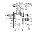
前記温水ユニット3内には、図2に示すように、メイン基板Kが設けられ、メイン基板KにはマイクロコンピュータM、水張りスイッチK1、暖房試運転スイッチK2、水張りランプK3、暖房試運転ランプK4等が設けられるとともに、基板端子には循環ポンプ9、熱動弁11、12、13、サーミスタ14、15、16、ボイラリモコン17、床暖房リモコン18、19、20、膨張タンク10に取り付けられた水位センサ21等が電気結線されている。
【0013】
また、前記マイクロコンピュータMには、図3に示すように、CPU、RAM、ROMが内蔵されるとともに、上述した各床暖房リモコン18〜20、各サーミスタ14〜16、各スイッチK1、K2、及び水位センサ21からの信号が入力されるとともに、室外ユニット1、循環ポンプ9、熱動弁11〜13、ボイラリモコン17、ランプK3、K4等に制御信号が出力される。
【0014】
床暖房パネル5の暖房を行う場合、先ずボイラリモコン17の運転スイッチ17bを操作すると、運転ランプ17cが点灯する。その運転信号が温水ユニット3内のメイン基板KのマイクロコンピュータMに入力されると、膨張タンク10内の循環水の有無を検出する水位センサ21に電圧を印加して循環水の有無を検出する。そして、この水位センサ21から循環水を介して電流が流れ、マイクロコンピュータMが水位センサ21からの水有り信号を入力すると、循環ポンプ9を運転して循環水を循環させるとともに、室外ユニット1に暖房運転信号を指示して暖房運転させる。
【0015】
この室外ユニット1が暖房運転することで、該室外ユニット1内のコンプレッサが運転して高温、高圧の冷媒が熱交換器4の冷媒側コイル4Aに供給され、温水側コイル4Bを流れる暖房循環水を加熱する。このときサーミスタ14で検出される暖房循環水の温度がボイラリモコン17の摘み17aで設定された設定温度になるように、マイクロコンピュータMが例えばコンプレッサをインバータ制御することにより熱交換器4での加熱量が制御され、床暖房パネル5に供給される循環水の温度が適度に調整される。このため、使用者がボイラリモコン17を操作することにより暖房循環水の温度を所望の温度とし、快適な床温あるいは室温とするものである。
【0016】
前記ボイラリモコン17の運転スイッチ17bをON(「オン」の意、以下同じ)した後、暖房したい部屋(例えばA室)に設置している床暖房リモコン18の運転スイッチ18aをONすると、対応している熱動弁11がONして温水が床暖房パネル6に供給され、A室の暖房が行われることとなる。
【0017】
その後、床暖房リモコン18は室温センサ18bにより室温上昇を検出し、温度偏差(室温−設定温度)が−1.15℃(deg)を超えると、メイン基板Kに出力しているアナログ出力電圧を20V(ボルト)から9Vの範囲で変化させる。そして、マイクロコンピュータMは床暖房リモコン18から出力されるアナログ電圧値に応じて、図4に示すように、前記熱動弁11の通電時間をデューティ制御し、熱動弁11の開時間を20分ごとに20分間(連続)から3分間に制御し、温水供給を断続的にON−OFF(オン−オフ)してA室の室温を設定温度に維持する。
【0018】
また、その他の床暖房パネル7、8に対応する床暖房リモコン19、20の運転スイッチ19a、20aをONすると、同様に、使用する部屋(B室、C室)の室温と設定温度とを比較演算した温度偏差信号がメイン基板Kに出力され、対応する熱動弁12、13のON−OFF時間を各々制御して各B室、C室の室温を制御する。
【0019】
このように、各A、B、C室に配置した床暖房リモコン18、19、20の出力する室温と設定温度との温度偏差により、熱動弁11、12、13の開閉時間を制御することにより、温水温度に関係なく各部屋の室温を設定温度に維持できる。
【0020】
尚、温水ユニット3による暖房運転中には室内ユニット専用リモコン(図示せず)の操作により室外ユニット1から冷媒配管を介して冷媒が供給される室内側熱交換器と室内空気とが熱交換され、室内ユニット2は室内に温風供給して暖房運転が可能であるが、このときは冷房運転は不可(できない)としており、また逆に、室内ユニット2の冷房運転中は温水ユニット3による暖房運転は不可としている。
【0021】
次に、循環ポンプの故障検知方法について、図5のフローチャートを参照して詳述する。先ず、ボイラリモコン17の運転スイッチ17bがONされていなければ、循環ポンプ9が運転されず、室外ユニット(ヒートポンプユニット)1へマイクロコンピュータMから出力停止が指示され、所定のT時間だけ該マイクロコンピュータM内のタイマーをリセットする。
【0022】
そして、床暖房パネル5の暖房を行うべくボイラリモコン17の運転スイッチ17bを操作すると、運転ランプ17cが点灯する。その運転信号が温水ユニット3内のメイン基板KのマイクロコンピュータMに入力されると、膨張タンク10内の循環水の有無を検出する水位センサ21に電圧を印加して循環水の有無を検出する。そして、この水位センサ21から循環水を介して電流が流れ、マイクロコンピュータMが水位センサ21からの水有り信号を入力すると、循環ポンプ9を運転して循環水を循環させるとともに、室外ユニット1に暖房運転信号を指示して暖房運転させる。
【0023】
室外ユニット1が暖房運転することで、該室外ユニット1内のコンプレッサが運転して高温、高圧の冷媒が熱交換器4の冷媒側コイル4Aに供給され、温水側コイル4Bを流れる暖房循環水を加熱する。このときサーミスタ14で検出される暖房循環水の往き温度がボイラリモコン17の摘み17aで設定された設定温度になるように、マイクロコンピュータMが例えばコンプレッサをインバータ制御することにより熱交換器4での加熱量が制御され、床暖房パネル5に供給される循環水の温度が適度に調整される。
【0024】
熱交換器4の冷媒側コイル4Aの入口近傍にはサーミスタ16が設けられ、このサーミスタ16で冷媒温度(TH1)を検知し、温水側コイル4Bの出口近傍にはサーミスタ14が設けられ、このサーミスタ14で暖房循環水の往き温度(TH2)を検知している。
【0025】
また、冷媒温度(TH1)の上昇に合わせて暖房循環水の往き温度(TH2)も上昇するが、熱交換器4には各種形式や流体条件によって定まる熱交換率があり、冷媒温度(TH1)と温水温度(TH2)の間には温度差が生じ、さらに、応答遅れや熱伝導の影響によりその温度差は変動するので、余裕をみて暖房循環水が正常に循環している場合の冷媒温度(TH1)と暖房循環水の往き温度(TH2)との温度差(△tmp)を設定する。
【0026】
そして、冷媒温度を検知するサーミスタ16が検知した冷媒温度(TH1)から、予め設定されている暖房循環水が正常に循環しているときに生じる冷媒と暖房循環水との熱交換率を含めた温度差(△tmp)を減算した温度が、暖房循環水の往き温度を検知するサーミスタ14が検知した暖房循環水の往き温度(TH2)より大きくなり、更にその状態が所定のT時間(マイクロコンピュータM内のタイマーが計時)継続していない場合には、現在の暖房循環水の往き温度(TH2)とボイラリモコン17の摘み17aで設定された設定温度の偏差により室外ユニット1の出力値をマイクロコンピュータMが演算し、室外ユニット1にその出力値を指示し、そのように運転させる。
【0027】
そして、サーミスタ16が検知した冷媒温度(TH1)が冷媒の高負荷となるような温度(高負荷温度)より高くなった場合は、室外ユニット1へ出力ダウンを指示し、冷媒が高負荷状態とならないようにする。この出力ダウンの結果、前記冷媒温度(TH1)が高負荷温度より下がれば、出力ダウン指示を解除する。これにより、室外ユニット1内にあるコンプレッサ及びそのシステムの冷媒配管が保護される。
【0028】
しかし、冷媒温度を検知するサーミスタ16が検知した冷媒温度(TH1)から、前記温度差(△tmp)を減算した温度が、暖房循環水の往き温度を検知するサーミスタ14が検知した暖房循環水の往き温度(TH2)より大きくなり、更にその状態が所定のT時間経過(マイクロコンピュータM内のタイマーが計時)した場合には、循環ポンプ9が故障したものとマイクロコンピュータMが判断し、この循環ポンプ9を停止し、同時にヒートポンプ式空気調和機の室外ユニット1への出力を停止する。この場合、循環ポンプ9が故障した旨を、ボイラリモコン17に表示ランプ等を設けて表示させるようにしてもよい。
【0029】
以上説明したように、本発明によれば、ヒートポンプ式空気調和機の室外ユニットと、この室外ユニットから供給される冷媒と暖房循環水との熱交換を行う熱交換器を有する温水ユニットとを備え、この温水ユニットの暖房循環水を循環ポンプにより床暖房パネル等に供給するヒートポンプ式温水暖房装置において、冷媒温度を検知するサーミスタが検知した冷媒温度(TH1)から、暖房循環水の往き温度を検知するサーミスタが検知した暖房循環水の往き温度(TH2)を減算した温度が、予め設定されている暖房循環水が正常に循環しているときに生じる冷媒と暖房循環水との熱交換率を含めた温度差(△tmp)より大きくなったうえに、その状態が所定のT時間継続したことを検知した場合に、前記循環ポンプが故障したものと判断する判断手段とを設けている。このため、循環ポンプ9が故障し熱交換器4の温水コイル側4Bの暖房循環水が循環しなくなると、冷媒コイル側4Aからの伝熱が行なわれず冷媒温度(TH1)が上昇し暖房循環水の往き温度(TH2)との温度差が、暖房循環水が正常に循環しているときに生じる冷媒と暖房循環水との熱交換率を含めた温度差(△tmp)より、大きくなるので循環ポンプの故障を検知することができる。
【0030】
また、暖房循環水回路中のフィルター(図示せず)や配管の目詰まりにより循環流量が低下した場合も、冷媒温度(TH1)が上昇し暖房循環水の往き温度(TH2)との温度差が、暖房循環水の正常に循環しているときに生じる冷媒と暖房循環水との熱交換率を含めた温度差(△tmp)より、大きくなるので目詰まりの発生を検知できる。
【0031】
なお、以上本発明の実施態様について説明したが、上述の説明に基づいて当業者にとって種々の代替例、修正又は変形が可能であり、本発明の趣旨を逸脱しない範囲で前述の種々の代替例、修正又は変形を包含するものである。
【0032】
【発明の効果】
以上のように本発明は、温度制御用の冷媒温度サーミスタと循環水温度サーミスタを使用して循環ポンプの故障を検知するので、循環ポンプの故障を検知するために特別に流水スイッチや流量センサーを設けなくて済むようになり安価にできる。
【図面の簡単な説明】
【図1】ヒートポンプ式温水暖房装置の全体系統図である。
【図2】メイン基板の電気配線図である。
【図3】制御装置のブロック図である。
【図4】制御装置の床暖房制御説明用の表である。
【図5】制御装置の動作説明用のフローチャートである。
【符号の説明】
1 室外ユニット
3 温水ユニット
4 熱交換器
4A 冷媒側コイル
4B 温水側コイル
14、16 サーミスタ
M マイクロコンピュータ(制御手段)[0001]
TECHNICAL FIELD OF THE INVENTION
The present invention includes an outdoor unit of a heat pump type air conditioner, and a hot water unit having a heat exchanger for performing heat exchange between a refrigerant such as HFC and CO 2 supplied from the outdoor unit and heating circulating water. The present invention relates to a heat pump type hot water heating apparatus that supplies heating circulating water of a hot water unit to a floor heating panel or the like by a circulation pump.
[0002]
[Prior art]
This type of conventional heat pump hot water heating apparatus supplies a high-temperature, high-pressure refrigerant of an outdoor unit of a heat pump air conditioner to an indoor unit and a hot water unit, and heats indoor air by the indoor unit to perform hot air heating. In addition, there is known an apparatus in which heating circulating water is heated by a heat exchanger built in a hot water unit, and heating circulating water of the hot water unit is supplied to a floor heating panel or the like by a circulation pump to perform hot water heating (for example, And Patent Document 1).
[0003]
[Patent Document 1]
JP-A-6-88628
[Problems to be solved by the invention]
However, in the above-described case, a failure of the circulation pump is detected by providing a flow switch in the hot water circulation circuit to which the circulation pump is connected to detect the presence or absence of water flow, or by providing a flow sensor and detecting the flow rate of hot water. However, it is necessary to provide a special water switch and a flow sensor for detecting the failure of the circulation pump.
[0005]
Therefore, an object of the present invention is to detect a failure of a circulation pump without providing a special flow switch or flow sensor.
[0006]
[Means for Solving the Problems]
Therefore, a first invention includes an outdoor unit of a heat pump type air conditioner, and a hot water unit having a heat exchanger for exchanging heat between a refrigerant supplied from the outdoor unit and heating circulating water. In a heat pump type hot water heating apparatus that supplies heating circulating water to a floor heating panel or the like by a circulating pump, a first temperature sensor for detecting a temperature of a refrigerant flowing to the heat exchanger, and a heating circulating water flowing to the heat exchanger A second temperature sensor for detecting an outgoing temperature, and a state in which the temperature obtained by subtracting the outgoing temperature of the heating circulating water detected by the second temperature sensor from the refrigerant temperature detected by the first temperature sensor is higher than a predetermined temperature for a predetermined time A determination means is provided for determining that the circulating pump has failed if continued.
[0007]
Further, the second invention includes an outdoor unit of a heat pump type air conditioner, and a hot water unit having a heat exchanger for performing heat exchange between a refrigerant supplied from the outdoor unit and heating circulating water. In a heat pump type hot water heating apparatus that supplies heating circulating water to a floor heating panel or the like by a circulating pump, a first temperature sensor that detects a temperature of a refrigerant flowing through the heat exchanger, and a flow of heating circulating water flowing through the heat exchanger. The second temperature sensor for detecting the temperature and the heating circulating water in which the temperature obtained by subtracting the outgoing temperature of the heating circulating water detected by the second temperature sensor from the refrigerant temperature detected by the first temperature sensor are normally set are normal. If the state in which the temperature difference including the heat exchange rate between the refrigerant and the heating circulating water generated during circulation is larger than the temperature difference continues for a predetermined time, the circulating pump may fail. Characterized in that a determining means for determining that.
[0008]
BEST MODE FOR CARRYING OUT THE INVENTION
Hereinafter, embodiments of the present invention will be described with reference to the drawings. FIG. 1 is a system diagram showing an entire system of a heat pump hot water heating apparatus. In FIG. 1,
[0009]
The
[0010]
14 is a thermistor as a temperature sensor for detecting the temperature of the heating circulating water that has been heated to a high temperature by the hot water side coil 4B of the
[0011]
[0012]
As shown in FIG. 2, a main board K is provided in the
[0013]
As shown in FIG. 3, the microcomputer M includes a CPU, a RAM, and a ROM, and further includes the above-described floor
[0014]
When heating the
[0015]
When the
[0016]
When the
[0017]
Thereafter, the floor heating
[0018]
When the operation switches 19a and 20a of the floor heating
[0019]
As described above, the opening and closing time of the
[0020]
During the heating operation by the
[0021]
Next, a method of detecting a failure of the circulation pump will be described in detail with reference to the flowchart of FIG. First, if the
[0022]
When the
[0023]
When the
[0024]
A
[0025]
Further, the outgoing temperature (TH2) of the heating circulating water also increases with the rise of the refrigerant temperature (TH1). However, the
[0026]
Then, based on the refrigerant temperature (TH1) detected by the
[0027]
Then, when the refrigerant temperature (TH1) detected by the
[0028]
However, the temperature obtained by subtracting the temperature difference (△ tmp) from the refrigerant temperature (TH1) detected by the
[0029]
As described above, according to the present invention, an outdoor unit of a heat pump air conditioner and a hot water unit having a heat exchanger that performs heat exchange between a refrigerant supplied from the outdoor unit and heating circulating water are provided. In a heat pump type hot water heating device that supplies the heating circulating water of the hot water unit to a floor heating panel or the like by a circulating pump, the outgoing temperature of the heating circulating water is detected from the refrigerant temperature (TH1) detected by a thermistor that detects the refrigerant temperature. The temperature obtained by subtracting the outgoing temperature (TH2) of the heating circulating water detected by the heating thermistor includes the heat exchange rate between the refrigerant and the heating circulating water generated when the preset heating circulating water circulates normally. If the temperature difference (温度 tmp) becomes larger than the temperature difference (Δtmp) and the state is detected to have continued for a predetermined time T, it is determined that the circulating pump has failed. It is provided determining means for. Therefore, when the
[0030]
Also, when the circulation flow rate is reduced due to clogging of a filter (not shown) or piping in the heating circulating water circuit, the refrigerant temperature (TH1) rises and the temperature difference from the outgoing temperature (TH2) of the heating circulating water increases. Since the temperature difference (△ tmp) including the heat exchange rate between the refrigerant and the heating circulating water generated when the heating circulating water is circulating normally becomes larger, the occurrence of clogging can be detected.
[0031]
Although the embodiments of the present invention have been described above, various alternatives, modifications or variations are possible for those skilled in the art based on the above description, and the various alternatives described above do not depart from the spirit of the present invention. , Modifications or variations.
[0032]
【The invention's effect】
As described above, the present invention uses a refrigerant temperature thermistor for temperature control and a circulating water temperature thermistor to detect a failure of the circulating pump. It is not necessary to provide it, and the cost can be reduced.
[Brief description of the drawings]
FIG. 1 is an overall system diagram of a heat pump type hot water heating apparatus.
FIG. 2 is an electrical wiring diagram of a main board.
FIG. 3 is a block diagram of a control device.
FIG. 4 is a table for explaining floor heating control of the control device.
FIG. 5 is a flowchart for explaining the operation of the control device.
[Explanation of symbols]
DESCRIPTION OF
Claims (2)
Priority Applications (1)
| Application Number | Priority Date | Filing Date | Title |
|---|---|---|---|
| JP2003021459A JP2004232947A (en) | 2003-01-30 | 2003-01-30 | Heat pump type water heater |
Applications Claiming Priority (1)
| Application Number | Priority Date | Filing Date | Title |
|---|---|---|---|
| JP2003021459A JP2004232947A (en) | 2003-01-30 | 2003-01-30 | Heat pump type water heater |
Publications (1)
| Publication Number | Publication Date |
|---|---|
| JP2004232947A true JP2004232947A (en) | 2004-08-19 |
Family
ID=32950789
Family Applications (1)
| Application Number | Title | Priority Date | Filing Date |
|---|---|---|---|
| JP2003021459A Pending JP2004232947A (en) | 2003-01-30 | 2003-01-30 | Heat pump type water heater |
Country Status (1)
| Country | Link |
|---|---|
| JP (1) | JP2004232947A (en) |
Cited By (3)
| Publication number | Priority date | Publication date | Assignee | Title |
|---|---|---|---|---|
| JP2006349195A (en) * | 2005-06-13 | 2006-12-28 | Sanyo Electric Co Ltd | Fault indication method for apparatus |
| CN103154626A (en) * | 2010-10-15 | 2013-06-12 | 东芝开利株式会社 | Heat source apparatus |
| CN110023683A (en) * | 2016-11-14 | 2019-07-16 | 庆东纳碧安株式会社 | The abnormal circulation control device and its control method of electric boiler |
-
2003
- 2003-01-30 JP JP2003021459A patent/JP2004232947A/en active Pending
Cited By (6)
| Publication number | Priority date | Publication date | Assignee | Title |
|---|---|---|---|---|
| JP2006349195A (en) * | 2005-06-13 | 2006-12-28 | Sanyo Electric Co Ltd | Fault indication method for apparatus |
| CN103154626A (en) * | 2010-10-15 | 2013-06-12 | 东芝开利株式会社 | Heat source apparatus |
| KR101496599B1 (en) * | 2010-10-15 | 2015-02-26 | 도시바 캐리어 가부시키가이샤 | Heat source apparatus |
| CN103154626B (en) * | 2010-10-15 | 2015-11-25 | 东芝开利株式会社 | Heat power supply device |
| CN110023683A (en) * | 2016-11-14 | 2019-07-16 | 庆东纳碧安株式会社 | The abnormal circulation control device and its control method of electric boiler |
| CN110023683B (en) * | 2016-11-14 | 2021-03-02 | 庆东纳碧安株式会社 | Circulation abnormality control device for electric boiler and control method thereof |
Similar Documents
| Publication | Publication Date | Title |
|---|---|---|
| JP5884042B2 (en) | Heat pump type hot water heater | |
| JP4549241B2 (en) | Heat pump type water heater | |
| JP4120683B2 (en) | Water heater abnormality detection device | |
| JP6471672B2 (en) | Hot water heating system | |
| JP6571540B2 (en) | Air conditioning indoor terminal, air conditioning system, and miswiring detection method | |
| JP2004205200A (en) | Heat pump type hot-water room heating system | |
| JP4493889B2 (en) | Air conditioning system | |
| AU2009227388B8 (en) | Heating and method for controlling the heating | |
| EP3608603B1 (en) | Heating medium circulation system | |
| JP3774615B2 (en) | Test run control method for hot water heater | |
| EP3258185B1 (en) | Heat supply system | |
| EP2589883A2 (en) | Heat pump hydronic heater | |
| JP2000018671A (en) | Heat pump type heating apparatus | |
| JP2004232947A (en) | Heat pump type water heater | |
| WO2018154768A1 (en) | Air conditioner | |
| EP3026364B1 (en) | Heat pump type heating and hot water supply apparatus | |
| JP4368295B2 (en) | Hot water heater | |
| JP2017072345A (en) | Heating device | |
| JP3850653B2 (en) | Heat pump type water heater | |
| JP7514423B2 (en) | Heat pump hot water supply system | |
| KR102382516B1 (en) | Water heater and controlling method for the same | |
| JP4368294B2 (en) | Hot water heater | |
| KR101450549B1 (en) | Heat pump heating apparatus and Control method of the same | |
| JP2006349195A (en) | Fault indication method for apparatus | |
| JP2001254991A (en) | Hot water air conditioner |
Legal Events
| Date | Code | Title | Description |
|---|---|---|---|
| A711 | Notification of change in applicant |
Free format text: JAPANESE INTERMEDIATE CODE: A712 Effective date: 20040819 |
|
| A521 | Written amendment |
Free format text: JAPANESE INTERMEDIATE CODE: A821 Effective date: 20040819 |
|
| A621 | Written request for application examination |
Free format text: JAPANESE INTERMEDIATE CODE: A621 Effective date: 20050802 |
|
| A977 | Report on retrieval |
Free format text: JAPANESE INTERMEDIATE CODE: A971007 Effective date: 20061220 |
|
| A131 | Notification of reasons for refusal |
Free format text: JAPANESE INTERMEDIATE CODE: A131 Effective date: 20070123 |
|
| A521 | Written amendment |
Free format text: JAPANESE INTERMEDIATE CODE: A523 Effective date: 20070322 |
|
| A02 | Decision of refusal |
Free format text: JAPANESE INTERMEDIATE CODE: A02 Effective date: 20070522 |