【0001】
【発明の属する技術分野】
本発明は、電子機器あるいは電気機器を構成する発熱性部品の冷却構造に関する。
【0002】
【従来の技術】
従来より、電子機器あるいは電気機器を構成する発熱性部品の冷却構造として、冷却用ファンによる冷却風を用いたもの(空冷)と液体冷媒を用いたもの(液冷)とが知られている。液冷は空冷に比較して冷却性能が高いため、特に発熱量の大きい発熱体を有する機器においては、液冷による冷却を行うことが提案されている。ただし、機器によっては、機器内のすべての発熱体の冷却を液冷により行おうとすると、冷却器が複雑化および大型化し、さらに液体冷媒を冷却するための装置も大型化するため、図4に示すように、発熱量が大きい発熱体90は液冷、発熱量が小さい発熱体91は空冷というように、発熱体の発熱量に応じて液冷と空冷を使い分けることにより、冷却構造を簡素化することも提案されている(例えば、特許文献1参照。)。
【0003】
【特許文献1】
特開平9−283958号公報
【0004】
【発明が解決しようとする課題】
しかしながら、従来の液冷による冷却構造においては、発熱体からの熱が外に逃げて液体冷媒によって確実に熱を集められず、特に上記従来技術のように、発熱体90を液冷により冷却する部分(液冷部)94と発熱体91を空冷により冷却する部分(空冷部)95が混在している場合には、空冷のための冷却風が液冷部94を通ることにより発熱体90からの熱が多く外に逃げて、このように高発熱の発熱体90から逃げた熱により高温になった風が風下にある空冷部95の発熱体91にあたることにより、空冷部95の発熱体91の温度が上昇するという問題があった。
【0005】
本発明は、上記点に鑑みなされたものであり、発熱性部品において発生した熱を外部に逃がすことなく液体冷媒により確実に集めることができる冷却構造を提供することを目的としている。
【0006】
【課題を解決するための手段】
上記課題を解決するため、請求項1記載の発熱性部品の冷却構造は、第1発熱体からの熱を受け取り可能に配置された冷却器を備えており、冷却器外部において冷却された第1冷媒を冷却器内に循環させることにより第1発熱体を冷却する冷却構造であり、さらに、第1発熱体と冷却器とを1つの密閉空間内に収めて周囲から熱的に遮断するケースを備えており、第1冷媒はケース外部において冷却されるように構成されていることを特徴としている。
【0007】
このような構成によると、第1発熱体と冷却器はケースにより周囲から熱的に遮断されているため、第1発熱体において発生した熱を外部に逃がすことなく、冷却器内の第1冷媒により確実に集めることができる。
【0008】
請求項2記載のように、ケースの周囲に、発熱量が第1発熱体より小さく、冷却用ファンからの冷却風により冷却される第2発熱体を備えた空冷部が配置されている場合には、請求項1記載のように、第1発熱体がケースによって周囲から熱的に遮断されていると、第1発熱体からの熱が第2発熱体に影響を与えることがなく、これにより第2発熱体の信頼性を向上することができる。この場合、請求項3記載のように、ケースと空冷部が冷却用ファンの風向に関して並列に配置されていると、冷却用ファンからの冷却風がケースにあたることがないため、第1発熱体からの熱をケース外に逃がすことなく冷却器によってより確実に集めることができ、また第1発熱体からの熱が第2発熱体に影響することをより確実に防ぐことができる。
【0009】
また、請求項4記載のように、ケースとして、熱的なシールドだけでなく、電磁的なシールドを兼ね備えたものを用いると、簡単な構造により、第1発熱体および冷却器を周囲から熱的にシールドすると共に、第1発熱体を電磁的にシールドすることが可能である。
【0010】
さらに、請求項5記載のように、第1冷媒は、ケース外部に配置された吸着器に循環させられて、吸着器内において第2冷媒を蒸発させ、蒸発した第2冷媒を吸着器内部の吸着剤に吸着することにより冷却されるように構成されているとよい。このように、ケース外において吸着式冷凍装置により第1冷媒を冷却するように構成されていると、第1冷媒を外気温度以下に冷却することが可能であるため、単にケース外部において第1冷媒から空気中へ放熱させることにより冷却する場合に比較して、外気温度に拘わりなく適切に冷却することが可能である。また、吸着式冷凍装置を用いると、他の冷凍装置に比較して、省電力での冷却が可能である。
【0011】
吸着式冷凍装置においては、請求項6記載のように、吸着剤から第2冷媒を脱離させるための熱源として、ケース外部に配置されている第3発熱体において生じる熱を利用するようにするとよい。このようにして、吸着式冷凍装置を作動させる際の熱源として、例えば第1発熱体と同じ機器内にある別の適当な発熱体などからの熱を利用すると、第1冷媒の冷却をより省電力で行うことができる。
【0012】
【発明の実施の形態】
(第1実施形態)
図1(A)および(B)は、本発明の第1実施形態に係る冷却構造が適用された電子機器1を示している。電子機器1は例えばワークステーションなどであり、比較的高い発熱性を有する電子部品である複数の第1発熱体3と、比較的低い発熱性を有する電子部品である第2発熱体4とを備えている。第1発熱体3は、例えばパワートランジスタなどであり、第2発熱体4は、第1発熱体3より発熱量が小さいDC/DCコンバータなどである。
【0013】
第2発熱体4は、金属製のヒートシンク5の上に取り付けられて、上部からケース6によって覆われており、これら全体によって空冷部20を形成している。ヒートシンク5は複数の放熱フィンを備えており、この放熱フィンには、冷却用ファン10から冷却風が吹きつけられるようになっている。第2発熱体4で発生した熱は、ヒートシンク5に伝わり、ここから冷却用ファン10からの冷却風に伝わり、このようにして第2発熱体4が冷却される。
【0014】
一方、第1発熱体3はプリント基板2上に形成されており、これらの第1発熱体3には、プリント基板2と反対側に金属製の冷却器7が取り付けられている。また、これらの第1発熱体3は、冷却器7と共にケース8内に収められており、これら全体によって液冷部30を形成している。液冷部30と空冷部20は、冷却用ファン10からの冷風の風向きに関して並列になるように配置されている。
【0015】
冷却器7は、ケース8内において、樹脂製の支持部材9により支持されており、これによりケース8から間隔をおいて配置されている。また、プリント基板2もケース8から間隔をおいて配置されており、このようにして、第1発熱体3および冷却器7はケース8と直接接触しないようにケース8内の密閉空間に収められている。ケース8は樹脂製で表面に金属メッキが施されており、これにより、第1発熱体3および冷却器7を、周囲(例えば第2発熱体4など)から熱的に遮断すると共に、電磁的にも遮断している。
【0016】
冷却器7は、図1(A)に示すように、3つの第1発熱体3の下を順に通るように配設されており、内部には液体冷媒が通るための通路が形成されている。通路の両端には、ケース8の外部から、入口配管14および出口配管15がそれぞれ接続されており、冷却器7内の通路に入口配管14から第1冷媒が供給され、出口配管15から放出されることにより、冷却器7内に第1冷媒が循環するようになっている。第1冷媒としては、水、アンモニアなどの自然冷媒、エチレングリコール系の不凍液が混入した水、フロリナートなどのフッ化炭素系冷媒、HCFC123、HFC134a等のフロン系冷媒、メタノール、アルコールなどのアルコール系冷媒、アセトンなどのケトン系冷媒を用いることができるが、本実施形態では水を用いている。
【0017】
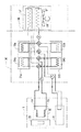
第1発熱体3で発生した熱は、冷却器7内の第1冷媒に伝わり、これにより第1発熱体3は冷却される。入口配管14および出口配管15は、図2に示すように、電子機器1外部の吸着式冷凍装置50に接続されており、出口配管15から放出された水は吸着式冷凍装置50の吸着器51a、51bにおいて冷却されて、再び入口配管14から冷却器7に供給される。
【0018】
吸着式冷凍装置50は、吸着剤による冷媒の吸着・脱離を利用して冷却を行うもので、第1吸着器51aと第2吸着器51bを有している。これらの吸着器51a51bは同じ構成のもので、吸着コア54a、54bと蒸発/凝縮コア55a、55bとを備えている。吸着器51a、51bの内部には、第2冷媒が封入されており、吸着コア54a、54bには吸着剤が充填されている。
【0019】
吸着剤としては、シリカゲル、ゼオライト、活性炭、活性アルミナなどを用いることができるが、本実施形態ではシリカゲルやゼオライト等の固体吸着剤を用いている。第2冷媒としては、吸着剤に吸着可能であり、圧力を変えることで相変化し熱の出入りがある水、フロン、アセトンなどを用いることができるが、本実施形態では水を用いている。
【0020】
この冷凍装置50は、第1吸着器51aにおいて冷却器7からの第1冷媒を冷却する第1モードと、第2吸着器51bにおいて冷却器7からの第1冷媒を冷却する第2モードで切り替えて作動する。
【0021】
図2は第1モードにおける状態を示している。第1モード開始時には、第1吸着器51a内の吸着剤は脱離が完了した状態にあり、第2吸着器51bの吸着剤は吸着が完了した状態にある。第1モードにおいては、蒸発コア55aにおいて第1吸着器51a内部の第2冷媒を蒸発させることにより、冷却器7からの第1冷媒を冷却する。蒸発した第2冷媒(水蒸気)は、第1吸着器51a内の吸着コア54aに拡散して、吸着剤により吸着される。吸着剤は水蒸気を吸着する際に発熱して吸着能力が低下するので、放熱器56において外気との熱交換により冷却された第3冷媒を吸着コア54a内に循環させることにより、吸着剤を冷却する。
【0022】
一方、第2吸着器51bにおいては、吸着コア54b内の吸着剤を加熱することにより、吸着剤に吸着していた第2冷媒を脱離させ、さらに凝縮コア55bに放熱器56からの第3冷媒を循環させることにより、脱離した気相冷媒(水蒸気)を冷却して凝縮させる。吸着剤を加熱するための加熱手段としては、電気ヒータなどを用いることもできるが、本実施形態では、図2に示すように、第1発熱体3と同じ電子機器1内に搭載されている別の発熱体(第3発熱体)40において生じる熱を利用している。ただし、この場合、第3発熱体40は、第1発熱体3の発熱量以上の発熱があることが条件となる。
【0023】
第2モードは、第2吸着器51b内の吸着剤は脱離が完了し、第1吸着器51a内の吸着剤は吸着が完了した状態において開始され、第1モードとは逆に、第2吸着器51bにおいて冷却器7からの第1冷媒を冷却し、第1吸着器51aにおいて第2冷媒の脱離および凝縮を行う。
【0024】
放熱器56においては、熱交換部57に対してファン58により冷却風が送られ、これにより,第3冷媒から周囲に放熱させることにより第3冷媒を冷却する。
【0025】
本実施形態の構成によると、液冷部30において、発熱体3と冷却器7がケース8内の密閉空間に収められて周囲から熱的に遮断されているため、発熱体3において発生した熱を冷却器7内の冷媒により確実に集めることができる。また、液冷部30がケース8で覆われており、空冷部20と液冷部30が並列に配置されていることから、液冷部30の発熱体3からの熱が空冷部20に影響を与えることがなく、これにより空冷部20の発熱体4の信頼性を向上することができ、また、機器1全体の冷却を効率的に行うことができる。さらに、液冷部30のケース8が電磁的シールドと熱的シールドを兼ねていることにより、簡単な構造により、第1発熱体3および冷却器7を周囲から熱的にシールドすると共に、第1発熱体3を電磁的にシールドすることを可能にしている。
【0026】
(他の実施形態)
本発明は上記実施形態に限定されることなく、つぎのように種々の変形が可能である。
【0027】
上記実施形態においては、ケース8は樹脂製の本体に金属メッキを施したものであったが、全体が金属により形成されているものであってもよい。
【0028】
上記実施形態においては、吸着式冷凍装置50において吸着剤を加熱するための加熱手段として、電子機器1内に搭載されている第3発熱体40からの熱を利用したが、電子機器がより大きな装置内に組み込まれている場合などには、この装置に搭載されている他の機器からの発熱を加熱手段として用いてもよい。例えば、車両に搭載されている電子機器の場合には、エンジンの冷却水などを吸着剤の加熱に用いることができる。
【0029】
また、図3に示すように、冷却器7において第1発熱体3からの熱を集めた第1冷媒を吸着器51a、51bの吸着コア54a、54bに循環させることにより、吸着剤から第2冷媒を脱離させるための加熱手段として第1発熱体3の熱を利用し、吸着器51a、51bの蒸発コア55a、55bには電子機器1内に搭載されている第4発熱体41からの熱を集めた第4冷媒を循環させて、蒸発コア55a、55b内で第2冷媒を蒸発させることにより第4冷媒を冷却するような構成にしてもよい。ただし、この場合、第1発熱体3からの発熱量を合わせたものが第4発熱体41の発熱量以上であることが条件となる。図3は、第1吸着器51aにおいて第4冷媒を冷却し、第2吸着器51bにおいて第2冷媒の脱離および凝縮を行うモードでの動作状態を示している。
【0030】
また、上記実施形態においては、冷却器7からの冷媒を吸着式冷凍装置50の吸着器51へ循環させることにより冷却する構成であったが、吸着式冷凍装置50を用いることなく、冷却器7からの冷媒を、図2に示す放熱器56と同様の外部の放熱器に直接循環させて、空気中への放熱のみにより冷却するように構成されていてもよい。
【0031】
上記実施形態においては、電子機器内の発熱性部品の冷却に本発明を適用したが、例えば電気変換器や蓄電池など電気機器内の発熱性部品の冷却に本発明を適用することもできる。
【図面の簡単な説明】
【図1】(A)は本発明の第1実施形態に係る冷却構造が適用された電子機器を示す平面図であり、(B)は(A)の線I−Iにおける断面図である。
【図2】冷却構造の全体構成を示す模式図である。
【図3】冷却構造の全体構成の変形例を示す模式図である。
【図4】従来の冷却構造が適用された電子機器を示す平面図である。
【符号の説明】
3 第1発熱体
4 第2発熱体
7 冷却器
8 液冷部のケース
10 冷却用ファン
20 空冷部
40 第3発熱体
51a、51b 吸着器[0001]
TECHNICAL FIELD OF THE INVENTION
The present invention relates to a cooling structure for a heat-generating component constituting an electronic device or an electric device.
[0002]
[Prior art]
2. Description of the Related Art Conventionally, as a cooling structure of a heat-generating component constituting an electronic device or an electric device, a structure using cooling air by a cooling fan (air cooling) and a structure using a liquid refrigerant (liquid cooling) are known. Since liquid cooling has higher cooling performance than air cooling, it has been proposed to perform cooling by liquid cooling, particularly for equipment having a heating element that generates a large amount of heat. However, depending on the device, if all the heating elements in the device are to be cooled by liquid cooling, the cooler becomes complicated and large, and the device for cooling the liquid refrigerant also becomes large. As shown, the cooling structure is simplified by selectively using liquid cooling and air cooling according to the heat generation amount of the heating element, such that the heating element 90 having a large heating value is liquid-cooled and the heating element 91 having a small heating value is air-cooled. It has also been proposed to do so (for example, see Patent Document 1).
[0003]
[Patent Document 1]
JP-A-9-283958
[Problems to be solved by the invention]
However, in the conventional cooling structure using liquid cooling, heat from the heating element escapes to the outside and the heat cannot be reliably collected by the liquid refrigerant. In particular, the heating element 90 is cooled by liquid cooling as in the above-described related art. When the part (liquid cooling part) 94 and the part (air cooling part) 95 for cooling the heating element 91 by air cooling are mixed, the cooling air for the air cooling passes through the liquid cooling part 94 to generate heat from the heating element 90. A large amount of heat escapes to the outside, and the wind heated to a high temperature by the heat escaping from the heat generating element 90 having high heat hits the heat generating element 91 of the air cooling section 95 located on the leeward side. However, there was a problem that the temperature rises.
[0005]
The present invention has been made in view of the above points, and has as its object to provide a cooling structure that can reliably collect heat generated in a heat-generating component by a liquid refrigerant without escaping to the outside.
[0006]
[Means for Solving the Problems]
In order to solve the above-mentioned problem, a cooling structure for a heat-generating component according to claim 1 includes a cooler arranged to receive heat from a first heating element, and the first structure cooled outside the cooler. A cooling structure that cools the first heating element by circulating the refrigerant in the cooler, and further includes a case in which the first heating element and the cooler are housed in one closed space and thermally isolated from the surroundings. And the first refrigerant is configured to be cooled outside the case.
[0007]
According to such a configuration, since the first heating element and the cooler are thermally isolated from the surroundings by the case, the heat generated in the first heating element does not escape to the outside, and the first refrigerant in the cooler does not escape. Can be collected more reliably.
[0008]
According to a second aspect of the present invention, in the case where an air-cooling unit having a second heating element that generates a smaller amount of heat than the first heating element and is cooled by cooling air from a cooling fan is disposed around the case. As described in claim 1, when the first heating element is thermally shielded from the surroundings by the case, heat from the first heating element does not affect the second heating element. The reliability of the second heating element can be improved. In this case, if the case and the air-cooling unit are arranged in parallel with respect to the wind direction of the cooling fan, the cooling air from the cooling fan does not hit the case. Can be more reliably collected by the cooler without escaping to the outside of the case, and the heat from the first heating element can be more reliably prevented from affecting the second heating element.
[0009]
Further, as described in claim 4, when the case has not only a thermal shield but also an electromagnetic shield, the first heating element and the cooler can be thermally isolated from the surroundings by a simple structure. And the first heating element can be electromagnetically shielded.
[0010]
Further, as described in claim 5, the first refrigerant is circulated to the adsorber disposed outside the case, evaporates the second refrigerant in the adsorber, and removes the evaporated second refrigerant inside the adsorber. It is good to be constituted so that it may be cooled by adsorbing on an adsorbent. As described above, if the first refrigerant is cooled by the adsorption-type refrigeration device outside the case, the first refrigerant can be cooled to the outside air temperature or lower. As compared with the case where cooling is performed by dissipating heat from the air into the air, it is possible to cool appropriately regardless of the outside air temperature. In addition, the use of an adsorption-type refrigeration apparatus enables cooling with lower power consumption than other refrigeration apparatuses.
[0011]
In the adsorption refrigerating apparatus, as described in claim 6, as a heat source for desorbing the second refrigerant from the adsorbent, heat generated in a third heating element disposed outside the case is used. Good. In this way, when the heat from the other suitable heating element in the same equipment as the first heating element is used as a heat source for operating the adsorption refrigeration apparatus, the cooling of the first refrigerant is further reduced. It can be done with power.
[0012]
BEST MODE FOR CARRYING OUT THE INVENTION
(1st Embodiment)
FIGS. 1A and 1B show an electronic device 1 to which a cooling structure according to a first embodiment of the present invention is applied. The electronic device 1 is, for example, a workstation or the like, and includes a plurality of first heating elements 3 which are electronic components having relatively high heat generation and a second heating element 4 which is an electronic component having relatively low heat generation. ing. The first heating element 3 is, for example, a power transistor or the like, and the second heating element 4 is a DC / DC converter or the like that generates less heat than the first heating element 3.
[0013]
The second heating element 4 is mounted on a metal heat sink 5 and is covered by a case 6 from above. The heat sink 5 has a plurality of radiating fins, and cooling air is blown from the cooling fan 10 to the radiating fins. The heat generated by the second heating element 4 is transmitted to the heat sink 5 and from here to the cooling air from the cooling fan 10, thereby cooling the second heating element 4.
[0014]
On the other hand, the first heating elements 3 are formed on the printed circuit board 2, and a metal cooler 7 is attached to the first heating elements 3 on the side opposite to the printed circuit board 2. The first heating elements 3 are housed in the case 8 together with the cooler 7, and the entirety thereof forms a liquid cooling section 30. The liquid cooling unit 30 and the air cooling unit 20 are arranged in parallel with respect to the direction of the cool air from the cooling fan 10.
[0015]
The cooler 7 is supported by a support member 9 made of resin in the case 8, and is arranged at a distance from the case 8. Further, the printed circuit board 2 is also arranged at a distance from the case 8, and thus the first heating element 3 and the cooler 7 are housed in a closed space inside the case 8 so as not to directly contact the case 8. ing. The case 8 is made of resin and metal-plated on the surface, so that the first heating element 3 and the cooler 7 are thermally insulated from the surroundings (for example, the second heating element 4 and the like) and electromagnetically. Is also shut off.
[0016]
As shown in FIG. 1A, the cooler 7 is disposed so as to pass under the three first heating elements 3 in order, and a passage through which the liquid refrigerant passes is formed inside. . An inlet pipe 14 and an outlet pipe 15 are connected to both ends of the passage from outside the case 8, respectively. The first refrigerant is supplied from the inlet pipe 14 to the passage in the cooler 7, and is discharged from the outlet pipe 15. This allows the first refrigerant to circulate in the cooler 7. Examples of the first refrigerant include natural refrigerants such as water and ammonia; water mixed with an ethylene glycol-based antifreeze; fluorocarbon-based refrigerants such as florinate; CFC-based refrigerants such as HCFC123 and HFC134a; and alcohol-based refrigerants such as methanol and alcohol. Although a ketone-based refrigerant such as acetone or acetone can be used, water is used in the present embodiment.
[0017]
The heat generated in the first heating element 3 is transmitted to the first refrigerant in the cooler 7, whereby the first heating element 3 is cooled. As shown in FIG. 2, the inlet pipe 14 and the outlet pipe 15 are connected to an adsorption refrigeration apparatus 50 outside the electronic device 1, and water discharged from the outlet pipe 15 is supplied to the adsorber 51 a of the adsorption refrigeration apparatus 50. , 51b and is supplied again to the cooler 7 from the inlet pipe 14.
[0018]
The adsorption refrigerating apparatus 50 performs cooling by utilizing adsorption and desorption of a refrigerant by an adsorbent, and has a first adsorber 51a and a second adsorber 51b. These adsorbers 51a and 51b have the same configuration, and include adsorption cores 54a and 54b and evaporation / condensation cores 55a and 55b. The second refrigerant is sealed inside the adsorbers 51a and 51b, and the adsorbent is filled in the adsorption cores 54a and 54b.
[0019]
As the adsorbent, silica gel, zeolite, activated carbon, activated alumina and the like can be used. In the present embodiment, a solid adsorbent such as silica gel and zeolite is used. As the second refrigerant, water, chlorofluorocarbon, acetone, or the like, which can be adsorbed by the adsorbent and undergoes a phase change by changing the pressure to allow heat to enter and exit, can be used. In the present embodiment, water is used.
[0020]
The refrigeration apparatus 50 switches between a first mode in which the first refrigerant from the cooler 7 is cooled in the first adsorber 51a and a second mode in which the first refrigerant from the cooler 7 is cooled in the second adsorber 51b. Work.
[0021]
FIG. 2 shows a state in the first mode. At the start of the first mode, the adsorbent in the first adsorber 51a is in a state where desorption is completed, and the adsorbent in the second adsorber 51b is in a state where adsorption is completed. In the first mode, the first refrigerant from the cooler 7 is cooled by evaporating the second refrigerant inside the first adsorber 51a in the evaporation core 55a. The evaporated second refrigerant (water vapor) diffuses into the adsorption core 54a in the first adsorber 51a and is adsorbed by the adsorbent. Since the adsorbent generates heat when adsorbing water vapor to lower the adsorbing ability, the third refrigerant cooled by heat exchange with the outside air in the radiator 56 is circulated through the adsorption core 54a to cool the adsorbent. I do.
[0022]
On the other hand, in the second adsorber 51b, the second refrigerant adsorbed on the adsorbent is desorbed by heating the adsorbent in the adsorbent core 54b, and the third refrigerant from the radiator 56 is conveyed to the condensing core 55b. By circulating the refrigerant, the desorbed gas-phase refrigerant (water vapor) is cooled and condensed. As a heating unit for heating the adsorbent, an electric heater or the like can be used, but in the present embodiment, as shown in FIG. 2, the adsorbent is mounted in the same electronic device 1 as the first heating element 3. The heat generated in another heating element (third heating element) 40 is used. However, in this case, a condition is that the third heating element 40 generates heat equal to or greater than the heat generation amount of the first heating element 3.
[0023]
The second mode is started when the adsorbent in the second adsorber 51b has been completely desorbed and the adsorbent in the first adsorber 51a has been completely adsorbed. The first refrigerant from the cooler 7 is cooled in the adsorber 51b, and the second refrigerant is desorbed and condensed in the first adsorber 51a.
[0024]
In the radiator 56, the cooling air is sent to the heat exchange unit 57 by the fan 58, and thereby the third refrigerant is cooled by radiating heat from the third refrigerant to the surroundings.
[0025]
According to the configuration of the present embodiment, since the heating element 3 and the cooler 7 are housed in the closed space in the case 8 and are thermally isolated from the surroundings in the liquid cooling section 30, the heat generated in the heating element 3 Can be reliably collected by the refrigerant in the cooler 7. Further, since the liquid cooling unit 30 is covered with the case 8 and the air cooling unit 20 and the liquid cooling unit 30 are arranged in parallel, heat from the heating element 3 of the liquid cooling unit 30 affects the air cooling unit 20. Thus, the reliability of the heating element 4 of the air cooling unit 20 can be improved, and the entire device 1 can be efficiently cooled. Further, since the case 8 of the liquid cooling unit 30 also serves as an electromagnetic shield and a thermal shield, the first heating element 3 and the cooler 7 are thermally shielded from the surroundings by a simple structure, The heating element 3 can be electromagnetically shielded.
[0026]
(Other embodiments)
The present invention is not limited to the above embodiment, and various modifications are possible as follows.
[0027]
In the above embodiment, the case 8 is formed by applying a metal plating to a resin body, but may be formed entirely of metal.
[0028]
In the above embodiment, as the heating means for heating the adsorbent in the adsorption refrigeration apparatus 50, the heat from the third heating element 40 mounted in the electronic device 1 is used, but the electronic device is larger. In the case where the device is incorporated in the device, heat generated from another device mounted on the device may be used as a heating unit. For example, in the case of an electronic device mounted on a vehicle, engine cooling water or the like can be used for heating the adsorbent.
[0029]
Further, as shown in FIG. 3, the first refrigerant, which has collected heat from the first heating element 3 in the cooler 7, is circulated to the adsorption cores 54a, 54b of the adsorbers 51a, 51b, so that the second refrigerant is removed from the adsorbent. Utilizing the heat of the first heating element 3 as heating means for desorbing the refrigerant, the evaporating cores 55a, 55b of the adsorbers 51a, 51b are supplied from the fourth heating element 41 mounted in the electronic device 1 to the evaporating cores 55a, 55b. A configuration may be adopted in which the fourth refrigerant that has collected heat is circulated and the fourth refrigerant is cooled by evaporating the second refrigerant in the evaporation cores 55a and 55b. However, in this case, it is a condition that the sum of the amounts of heat generated from the first heating elements 3 is equal to or more than the amount of heat generated by the fourth heating elements 41. FIG. 3 shows an operation state in a mode in which the fourth refrigerant is cooled in the first adsorber 51a and the second refrigerant is desorbed and condensed in the second adsorber 51b.
[0030]
Further, in the above embodiment, the refrigerant from the cooler 7 is cooled by being circulated to the adsorber 51 of the adsorptive refrigeration apparatus 50. However, the cooler 7 is used without using the adsorptive refrigeration apparatus 50. The refrigerant may be directly circulated to an external radiator similar to the radiator 56 shown in FIG. 2 so as to be cooled only by radiating heat into the air.
[0031]
In the above embodiment, the present invention is applied to cooling of a heat-generating component in an electronic device. However, the present invention can also be applied to cooling of a heat-generating component in an electric device such as an electric converter or a storage battery.
[Brief description of the drawings]
FIG. 1A is a plan view showing an electronic apparatus to which a cooling structure according to a first embodiment of the present invention is applied, and FIG. 1B is a cross-sectional view taken along line II of FIG.
FIG. 2 is a schematic diagram showing an overall configuration of a cooling structure.
FIG. 3 is a schematic diagram showing a modification of the overall configuration of the cooling structure.
FIG. 4 is a plan view showing an electronic device to which a conventional cooling structure is applied.
[Explanation of symbols]
3 First Heating Element 4 Second Heating Element 7 Cooler 8 Liquid Cooling Case 10 Cooling Fan 20 Air Cooling Section 40 Third Heating Element 51a, 51b Adsorber