JP2004232329A - Repairing method for drain installing pipe and using support carriage - Google Patents

Repairing method for drain installing pipe and using support carriage Download PDF

Info

Publication number
JP2004232329A
JP2004232329A JP2003021878A JP2003021878A JP2004232329A JP 2004232329 A JP2004232329 A JP 2004232329A JP 2003021878 A JP2003021878 A JP 2003021878A JP 2003021878 A JP2003021878 A JP 2003021878A JP 2004232329 A JP2004232329 A JP 2004232329A
Authority
JP
Japan
Prior art keywords
rubber
reversing
repair
pipe
tip
Prior art date
Legal status (The legal status is an assumption and is not a legal conclusion. Google has not performed a legal analysis and makes no representation as to the accuracy of the status listed.)
Granted
Application number
JP2003021878A
Other languages
Japanese (ja)
Other versions
JP3685494B2 (en
Inventor
Hideyoshi Kimura
栄喜 木村
Current Assignee (The listed assignees may be inaccurate. Google has not performed a legal analysis and makes no representation or warranty as to the accuracy of the list.)
Individual
Original Assignee
Individual
Priority date (The priority date is an assumption and is not a legal conclusion. Google has not performed a legal analysis and makes no representation as to the accuracy of the date listed.)
Filing date
Publication date
Application filed by Individual filed Critical Individual
Priority to JP2003021878A priority Critical patent/JP3685494B2/en
Publication of JP2004232329A publication Critical patent/JP2004232329A/en
Application granted granted Critical
Publication of JP3685494B2 publication Critical patent/JP3685494B2/en
Anticipated expiration legal-status Critical
Expired - Lifetime legal-status Critical Current

Links

Images

Abstract

<P>PROBLEM TO BE SOLVED: To reclaim and repair an installing part for a drain installing pipe and a main pipe by simultaneously performing reclaiming-repairing work for the buried drain installing pipe communicating with a sewerage main pipe from a house inlet and a street inlet without digging-up. <P>SOLUTION: A repairing material 5 including a cylindrical repairing cloth material 51 impregnated with a synthetic resin and cylindrical reversing rubber 4 are linked, and are installed in a reversing guide 2. The reversing rubber 4 and the repairing material 5 are reversely inserted into the drain installing pipe P<SB>1</SB>from the reversing guide 2 by the action of a high pressure fluid A on the reversing rubber 4 so that the repairing material 5 becomes the outside of the reversing rubber 4, and the repairing cloth material tip 51<SB>E</SB>is projected in the main pipe P<SB>o</SB>, and the reversing rubber 4 is pressurized and expanded in contact with a support plate 94 arranged in the main pipe P<SB>o</SB>, and a swelling balloon 4B is formed on the tip of the reversing rubber 4. The repairing material 5 is brought into pressure contact with an inner peripheral surface of an installing pipe P<SB>1</SB>, and the impregnated synthetic resin is hardened in a state of expansively opening the repairing cloth material tip 51<SB>E</SB>in pressure contact in the form of a collar R for covering an installing pipe port PE, and the reversing rubber 4 is extracted after hardening, and a repairing-reclaiming pipe is formed of one repairing cloth material 51. <P>COPYRIGHT: (C)2004,JPO&NCIPI

Description

【0001】
【発明の属する技術分野】
本発明は、工場や家庭の汚水桝や雨水桝から地中へと連設された排水取付管の補修方法及び該方法に用いる補修装置に関するものであり、より詳しくは、工場や宅内に設置された汚水桝や雨水桝から下水道本管に接続された既設の埋設排水取付管に亀裂や破損が生じた際に、掘り起こすことなく非開削で取付管内面に補修材層を張設して取付管を更生する技術に関する。
【0002】
【従来の技術】
〔特許文献1〕特開2001−30357号公報
各家庭内には宅内桝、即ち汚水桝が設置してあり、該汚水桝から道路下面の下水道本管までは地中に埋設した排水取付管で連通してあるが、取付管は経年変化による老朽化や外的荷重、或いは地震等によって破損や継目の開離が生じ、これに伴う地下水や土砂の流入、或いは汚水の地中への流出等が生じるため、取付管の修繕改築が必要となる。
【0003】
従来の、宅内桝から下水道本管へ連結した排水取付管の最も一般的な修繕改築方法は、取付管に単にひび割れ等で漏水を生じている程度の場合でも、埋設されている取付管を掘り出して既設取付管を撤去し、新たに取付管を設置埋設する開削工法である。
しかし、市街地での該開削工法では、道路を掘り返すため、交通事情に悪影響を及ぼす点、近隣住民への影響等、住環境問題面から好ましくない。
従って、近年は、このような開削工法に代る非開削工法が開発され、実用化されている。
【0004】
非開削工法としては、IPC(Inversion Chemical Pipe)ブリース工法やLIP(Lateral in Pipe)工法の反転工法があり、IPCブリース工法は、合成樹脂含浸補修材の反転挿入を本管側から取付管側へ圧縮空気によって行い、温水を補修材内へ充填注入して補修材を硬化させるものであり、LIP工法は、宅内の汚水桝側で補修材の端部を取付け、圧縮空気によって既設取付管内に補修材を反転挿入し、補修材を硬化後、本管内及び汚水桝内に突出した部分を切断除去するものである。
【0005】
本発明者は、IPCブリース工法やLIP工法とは全く異なる画期的な排水取付管補修の新規工法を、特願2000−309158号(特開2001−30357号)として提案した。
即ち、該提案発明は、図16に示すものであって、硬化性合成樹脂を含浸させた補修材5を反転ゴム4と接続紐12で連係させて共に反転ガイド2内に装着し、高圧流体Aを供給しながら反転ロープ11によって反転ゴム4と補修材5とを共に排水取付管P内に反転挿入し、図16(B)の如く、補修材5の布材51で取付管Pの内面を被覆圧接した状態で補修材の布材51を硬化処理し、図16(C)の如く、排水取付管Pの内周全面を布材51の硬化管層で更生補修するものである。
【0006】
【発明が解決しようとする課題】
図16の画期的な排水取付管補修方法は、補修材5を反転ゴム4が圧接した状態で補修材を硬化処理するため、布材51によって形成される更生管層の内面は、流水に支障を生ずるような皺は発生せず平滑面となり、また、反転ゴム4の反転挿入可能な形態の取付管全てに補修施工が可能となるもので、作業面からも、補修更生管の品質面からも、極めて優れたものである。
【0007】
しかし、図16(B),(C)に示す如く、取付管Pの内周面に対する布材51による新規更生管層の形成であるため、排水取付管Pの管口PEでは、取付管P内から本管P内に至るクラックKや、取付管Pと本管Pとの連結部の隙間Kの補修は出来ない。
そして、クラックKや隙間Kの存在は、取付管周囲の地層からの雨水や地下水、土砂等の本管P内への流入を生ずるため、必要に応じて、別途本管P内側から別の補修材で、取付管口PE周囲を補修する必要がある。
本発明は、該図16の補修方法を画期的に改善するものであり、特願2000−309158号(特開2001−30357号)の発明の実施に際し、1本の補修布材51によって取付管内周面の更生補修と同時に、取付管口PEの周囲をも補修可能とするものである。
【0008】
【課題を解決するための手段、及び作用】
本願の補修方法の発明は、例えば図1、図2に示す如く、合成樹脂を含浸させた筒状の補修布材51を含む補修材5と、筒状の反転ゴム4とを連係させて反転ガイド2内に装着し、高圧流体Aの反転ゴム4への作用によって、反転ゴム4及び補修材5を反転ガイド2から排水取付管P内へ、補修材5が反転ゴム4の外側になるように反転挿入して補修布材先端51(図13)を本管P内に突出し、反転ゴム4を本管P内に配置した支持プレート94に当接加圧膨張して反転ゴム4の先端に膨出バルーン4Bを形成し、補修材5を取付管P内周面に圧接すると共に、補修布材先端51を取付管Pの管口PEを覆う鍔R形態に拡開圧接した状態で含浸合成樹脂を硬化し、補修布材51の硬化後に反転ゴム4を引抜き、反転ガイド2を補修材5から切離すものである。
【0009】
尚、補修布材としては、長さ方向及び径方向に自在に変形する従来の補修材が適用出来、布材先端51が鍔R状に拡開変形可能な編地組織、又は拡開用切れ目を入れた布の重層形態としても使用可能であるが、典型的には、合成樹脂の含浸保持能、及び変形自在性を備えている横メリヤスパイル組織の筒状編布である。
また、膨出バルーン4Bは、図1に示す如く、補修布材先端51を管口PEの外側に鍔R形態に押圧すれば良く、支持プレート94による膨出バルーン4Bの変形形態も補修布材先端51の寸法に応じて決定すれば良い。
また、筒状の補修材5の筒状の反転ゴム4との連係は、反転ゴム4の反転挿入時に補修材5が共に反転挿入されれば良く、補修材の基端5が反転ガイドに保持され、補修布材先端51が反転ゴム4の内側に引込まれていれば良い。
また、支持プレート94は、反転ゴム4の頭部の膨出を支持して膨出バルーン4Bが補修布材先端51を管口PEに押圧するように膨出バルーン4Bを規制すれば良く、手作業で本管P内に配置固定した板材でも、或いは本管P内で移動可能な車台に取付けた板材でも良い。
【0010】
尚、ここで言う、「取付管P」は、宅内桝から下水道本管へ連結した取付管をはじめ、家庭や工場の雨水桝から下水道本管に連結した排水取付管や、工場の廃液処理桝からの排水用取付管等、地表に設置した水溜め(桝)から地下の排水本管P(下水道本管)に連結した地中埋設の取付管を広く意味するものであり、「反転ゴム」は、合成ゴム、天然ゴム等、ゴム弾性を有するシート材等、膨出バルーン4Bの形成出来る材料を広く意味するものであり、「合成樹脂」は、光硬化、熱硬化、自然硬化(経時硬化)する合成樹脂を広く意味するものであり、「流体」は、空気、加熱又は常温の水、ガス等を意味するものである。
【0011】
従って、補修材5は、高圧流体作用を受ける反転ゴム4と共に反転ガイド2から取付管P内へ連係して一緒に反転挿入されるため、反転ゴム4の反転挿入可能な場所は全て補修材の反転挿入も可能であり、取付管Pが弯曲、或いは屈曲していても補修材の取付管P内への挿入配置は可能である。
更に、寸法安定性に乏しい補修材5が反転ゴムの外側へ反転されて行くため、補修材の反転挿入部が反転ゴム4の膨張加圧力で、順次取付管P内周面に押圧されて行き、取付管Pの屈曲部での補修材の皺の発生も最小限となり、例え少し発生する皺も反転ゴム4の加圧によって補修材5の反転ゴム4と当接した内周面は流路として支障のない程度の平滑面となる。
【0012】
更に、補修材5の反転挿入作業は、反転ガイド2先端を取付管Pの入口部に近接配置して実施出来るため、補修材5の必要長は補修対象取付管Pの長さに対応設定出来、従来の反転硬化工法(LIP工法)の如き補修材の先端部と基部での長寸の切断廃棄部分が生じなく、補修材及び合成樹脂等の材料の使用が合理化出来る。
更に、補修材5の反転挿入のための準備作業が補修対象取付管Pから離れた地上で実施可能であるため、施工準備作業が合理化出来る。
【0013】
しかも、補修布材先端51を本管P内に突出した段階で反転ゴム4の先端を支持プレート94に当接して加圧膨張させるため、膨出バルーン4Bは、比較的小径のバルーンを横方向拡開偏平形態とすることにより、補修布材先端51を管口PEに鍔Rの形態で当接出来、鍔Rの形成が、反転ゴムの負荷を最少限に抑制して合理的に実施出来る。
そして、鍔Rは取付管Pの管口PEに当接硬化するため、図16に示す如き取付管Pから本管Pへと連なるクラックKや、取付管Pと本管Pとの取付部の隙間Kを閉止補修出来、本発明の補修は、取付管内周面の更生補修施工に加え、従来では別施工でしか実施出来なかった取付管口PEの補修も同時に施工出来る。
従って、本発明によれば、取付管Pの内周全面と、取付管Pの本管Pへの取付部の管口PEとが、同時に補修布材51によって更生補修出来、排水取付管の画期的な補修手段の提供が可能となる。
【0014】
また、本願補修方法の発明にあっては、反転ゴム4が支持プレート94に当接した状態で反転ゴム4の反転作用を停止し、次いで、反転ゴム4内の高圧流体Aの圧力のみを増加し、反転ゴム4の先端を支持プレート94と管口PE間で偏平に変形した膨出バルーン4Bとするのが好ましい。
支持プレート94は、図13に示す如く、本管P内で移動可能であるので、補修布材先端51が本管P内に露出した段階で反転作業を中断して支持プレート94を取付管口PEに配置すれば良い。
そして、反転ゴム4は、先端の突出長を支持プレート94への当接で固定するため、反転ゴム4の膨出負荷を鍔Rの形成に必要な程度に抑制出来る。
【0015】
従って、反転ゴム4が支持プレート94に当接した状態で反転ゴムの反転作用を停止するため、反転ゴム4の先端の突出量を最少限に抑制出来、支持プレート94による規制された膨出バルーン4Bの偏平形態変形によって、補修布材先端51への合理的な当接押圧が可能となり、反転ゴム4の膨出負荷の規制された比較的小さな偏平形態の膨出バルーン4Bによって、補修布材先端51での管口PEの被覆に必要な鍔Rの形成が可能となる。
【0016】
また、本願補修方法の発明にあっては、支持プレート94を取付管Pの管口PEに略平行に配置するのが好ましい。
尚、「管口PEに略平行」の意味は、管口PEの仮想平面と支持プレート94が略平行を意味し、取付管口PEが地面に対して傾斜して本管Pに開口しておれば、支持プレート94も傾斜配置することを意味する。
従って、支持プレート94を管口PEに略平行配置するため、反転ゴム4の先端の膨出バルーン4Bの支持プレート94による偏平化変形は管口PEに対して均斉となり、比較的小さな膨出バルーン4Bであっても布材先端51による均斉な鍔Rの形成が合理的に実施出来、強度劣下及び損傷の生じ易い反転ゴム4の耐久性が向上する。
【0017】
また、補修材5の基端5を反転ガイド2の先端2の外周に締着し、補修材先端5を反転ゴム4内に引込んで接続紐12によって反転ゴム先端4と接続し、反転機1の巻芯13から巻戻しされる反転ロープ11に反転ゴム先端4を接続し、反転ゴム4の反転ガイド2からの排水取付管P内への反転延出によって補修材5を反転ゴム4の外側へ反転延出するのが好ましい。
この場合、接続紐12と補修材先端5との接続は、反転ゴム4の引抜き作用により解除される程度の弱い仮固定で実施出来る。
【0018】
従って、補修材基端5が反転ガイド2の先端2の外周に締着されているため、補修材5の反転ガイド先端2からの反転作用がスムーズとなり、反転ガイド先端2を取付管Pの口部に近接して施工することにより補修材5の補修後の廃棄長を最少限に節約出来、使用材料の合理化が可能となる。
更に、補修材先端5と反転ゴム先端4間には接続紐12が存在するため、補修材5の反転ゴム4内への挿入作業は、接続紐12を引張ることによって容易となり、反転ガイド2内への補修材5及び反転ゴム4の装着作業も容易となる。そして、反転ゴム4は、補修材5全長を取付管P内に反転挿入した後も補修材先端5を越えて反転挿入出来、反転ゴム先端の膨出バルーン4Bの選択形成も可能となり、補修材5の鍔R部分を含む全長を覆って加圧することにより、補修材5の取付管P内周面全長と取付管口PEの鍔Rに対する押圧硬化が均斉に実施出来る。
【0019】
また、補修材5が、少なくとも合成樹脂の含浸した布材51と、外側のシート52と、内側のシート53の遊離重層形態の3層を含んでいるのが好ましい。
布材51、外側シート52、内側シート53が遊離形態であれば、図7の如く、補修材5への合成樹脂液の含浸注入作業が容易であると共に、補修材5の取付管P内周面への当接順応性、及び布材先端51の鍔R形態での管口PEへの当接性も良くなり、しかも、硬化処理後の内周面のシート52(外側シートが反転したもの)の引き剥がしも容易である。
【0020】
布材51としては、合成樹脂を含浸保持し易い厚みを備え、且つ変形自在なもの、即ち、径及び長さ変化(縦、横変化)の容易な横メリヤスパイル布が好ましく、また、内外層のシート53としては、施工過程で合成樹脂液を保持する機能を奏すれば良いが、反転作用で取付管P内周面に当接する内側シート53は補修後も取付管P内周面と補修布材51間に残存するため、取付管Pからの漏水を閉止する機能を発揮する耐水性フィルムが好ましく、ゴムシートを適用すれば、小地震等による補修更生管層51への小振動応力も好適に吸収して補修取付管Pを保護する機能が期待出来るので好ましい。
また、外側シート52は、反転により補修布材51の内側となるため、補修施行後の反転ゴム4の引抜きと共に剥離破断出来るものが良い。
典型的には、外側シートも内側シートも、薄くて水不透過の合成樹脂フィルムが施工面、及び入手面から好適である。
【0021】
また、補修材5の外側シート52が先端に延出部52を備え、布材51が内側シート先端53から補修材先端51を突出しているのが好ましい。
この場合、外側シートの延出部52のみを接続紐12に止着して補修材先端5を反転ゴム先端4と接続出来、補修材5の硬化後の反転ゴム4の引抜き作用により、硬化補修材5の内面に存在する外側シート52を小さな引張り力で補修布材51からきれいに剥離除去出来、従って、延出部52の存在により、補修材5の反転ゴム4との仮固定及び切離しが容易となる。
そして、延出部52は、外側シート52のみであって、反転ゴム4の反転作用によって布材51の内側となるため、反転ゴム4の膨出バルーン4B形成時には、反転ゴム4の拡開作用によって破れるが、反転ゴム引抜き時には接続紐12によって支障なく剥離脱去出来る。
【0022】
また、外側シート52の延出部52には、図6(D)の如く、長手方向の裂け目C52を形成しておくのが好ましい。
この場合、補修材5及び反転ゴム4の反転作用終了後の反転ゴム先端による膨出バルーン4B形成作業時に、反転ゴム4による外側シート52の裂開が所定位置から縦方向にスムーズに遂行出来、膨出バルーン4Bで破られた外側シート52が接続紐12と連なった形態となるため、鍔Rの硬化処理後の反転ゴム4の引抜きに伴う接続紐12による外側シート52の剥離脱去が、スムーズに実施出来る。
【0023】
また、反転ゴム基端4及び補修材基端5を共に反転ガイド2に対して空密的に保持し、補修材5の反転中の先導部5に高圧流体aの圧力を付与した状態で補修材5を反転ゴム4で反転挿入するのが好ましい。
補修材5を、先端5の垂れた状態で反転ゴム4によって反転挿入する場合は、取付管内面の直角屈曲角や小さな摩擦突起等により補修材5に皺を生ずる危険があるが、図16に示す如く、補修材5の反転先導部5に高圧流体aの圧力を作用させながら反転ゴム4に先導的に反転挿入するので、補修材5自体も反転ゴム同様に、取付管P内の角や小突起に関係なく、膨張形態で平滑に順次反転挿入出来、従って、補修材5は皺を発生することなく取付管P内に反転挿入出来て、補修布材先端51も設計どおりに本管P内に突出出来、結局、取付管P内周面の形態に関係なく内面の平滑な取付管補修、及び取付管口PEの均斉な鍔R被覆補修が可能となる。
【0024】
また、反転ゴム4に反転機1からの高圧流体Aを供給する反転ガイド2の流路に流路遮断用のバルブVを配置し、反転ゴム4が補修材5全長を反転挿入して取付管P内周面に圧接加圧すると共に、先端の膨出バルーン4Bで補修布材先端51を管口PEに鍔R形態で圧接した段階でバルブVが反転ガイド2の流路を遮断し、反転ゴム4の高圧膨張状態を維持して補修材5を硬化するのが好ましい。
【0025】
この場合、反転機1は、バルブVの流路遮断作用中は圧力付与のための稼動の必要は無く、従って、比較的長時間を要する補修材5の硬化作業(自然硬化:85〜115分)中は、反転機1は休止することが出来、バルブ作用によって反転機の稼動エネルギーが節約出来るのは勿論、反転機に次の作業の準備をすることも、或いは硬化作業中の反転ガイド2から反転機を切離して次の現場へ移動して稼動することも可能となるため、設備費のかかる反転機の稼動率向上が達成出来、排水取付管P補修作業の経済的、合理的施工が可能となる。
【0026】
また、バルブVが反転ガイド2の流路に設けたゴム筒25と、該ゴム筒25の圧接手段33,34,35とを含み、ゴム筒25の圧接手段の下流には調整バルブVを介した高圧流体調整用のチューブt1を付設するのが好ましい。
この場合は、ゴム筒25を両側から圧接するだけでバルブVの閉止が可能となるため、例えば、図9(B)に示す如き、進退用スクリューロッド34の先端に圧接板35を取付けた単純なバルブ開閉手段で容易に実施出来る。
しかも、消耗品としてのゴム筒25の空密的取付けも、両端をバルブ装着用に切離した両側の反転ガイド端にバンドで空密的に締着するだけで可能であり、ゴム筒25の取換えが容易となる。
【0027】
そして、バルブVには圧力計M及び調整バルブVを設けてバルブVの下流側(加圧力維持側)の圧力を検知し、圧力減が生じた際には、調整バルブVから圧力流体を補充する慣用の圧力機器からチューブt1を介して圧力流体A1を付加することにより、膨出バルーン4Bの高圧状態が維持出来、少々の圧力漏れの生ずる若干ラフなバルブVの採用も可能となり、バルブの製作面からも、作業実施面からも有利となる。
【0028】
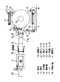
また、本願補修方法の発明の実施に用いるための支持台車SVは、図10に示す如く、車輪91を備え、ロープ92aによって前後移動可能な車台90の前部と後部に一対の角度調整枠93を配置し、下面にステ−95を備えた支持プレート94を前後の角度調整枠93間に張設し、支持プレート94の加圧降下によってステ−95が着地し、車台90の移動を阻止する構造である。
【0029】
尚、角度調整枠93は、支持プレート94が反転ゴム4先端の膨出バルーン4Bを適切に支持出来るように、排水取付管Pの管口PEの本管Pに対する接続角度に応じて車台90に対して、即ち水平面に対して、支持プレート94を傾斜調整付設可能とするものであるので、支持プレート94を角度調整可能に取付けられれば良く、支持プレート94を角度0°(水平)から左右45°位まで調整傾斜可能であれば通常の排水取付管Pの補修が可能である。
また、ステ−95は、支持プレート94の自由状態、即ち、無負荷状態では、下端95が車台90の下面から若干下方に突出した形態に構成すれば良く、支持プレート94の降下寸法との関係でステ−下端95の突出寸法を決定すれば良い。
また、支持プレート94は、前後両端をゴム板、スプリング等のバネ弾性を備えた形態で角度調整枠93に取付ければ良い。
【0030】
本発明の支持台車SVは、支持プレート94が排水取付管Pの管口PEの取付角度に対応して角度調整の下に取付けるため、補修対象取付管Pに応じて支持プレート94を管口PE面に平行に配置出来、反転ゴム4の頭部に形成する膨出バルーン4Bを、合理的に、且つ、補修布材先端51が均斉な鍔Rを管口PEの周囲に形成出来るように、支持プレート94を配置出来る。
【0031】
また、膨出バルーン4Bが支持プレート94を押圧すれば、支持プレート94の降下によってステ−下端95が着地して支持台車SVの移動を阻止するため、膨出バルーン4Bによる補修布材先端51の鍔R形態での硬化処理中の長時間の押圧状態を適切に維持出来、鍔Rの硬化処理が高品質に実施出来る。
しかも、ステ−95は、支持プレート94の自由状態では、下端95が地面から浮上った状態であるため、支持台車SVの本管P内での移動は、ステ−下端95が本管P底部の土石に妨害されずに、車輪のみで平滑に実施出来る。
【0032】
また、本発明の支持台車SVにあっては、前後の角度調整枠93間に弾性変位可能にゴム板96を張設し、支持プレート94とステ−95とをゴム板96に挟着固定するのが好ましい。
この場合は、ゴム板96の前端及び後端を角度調整枠93に取付け、前後の角度調整枠93と支持プレート94の前後端の間にゴム板のみの弾性変位域96を形成するだけで、支持プレート94及びステ−95に所望機能が付与出来、図12の如く、ゴム板96を、弾性変形域96を残して上面の支持プレート94と下面のステ−95とで締着ボルト等で挟着固定すれば良いので、支持台車SVの製作が簡単、且つ容易となる。
【0033】
また、前後一対の角度調整枠93が左右両側に調整孔Ahを備え、ゴム板96の前後端部96の左右側端を調整孔Ahへ選択固定して、ゴム板96を車台90に対して角度調整自在とするのが好ましい。
この場合、ゴム板96の前後端の各左右側端と角度調整枠93の調整孔Ahとを慣用の締着ボルト、係止ピン等で固定すれば良く、ゴム板側にネジボルトや係止ピンを付設して置けば良いが、図12(B)の如く、ボルト孔98hを備えた挟着板(取付プレート)97Bを固定し、ゴム板の左右側端に亘って1本の調整ボルト(ネジボルト)98を挿通するのが好ましい。
従って、ゴム板96の前後端部96を角度調整枠93に選択固定するだけで、支持プレート94は取付管口PEの傾斜に対応した傾斜角に設定出来、ゴム板96の着脱が容易であるため、各作業場所での支持プレート94の傾斜調整が容易であると共に、消耗品であるゴム板の取換えも容易である。
【0034】
また、本発明の支持台車SVにあっては、図11に示す如く、角度調整枠93が環状板C93であり、左右両側の略1/4周長に、スリットSと切込み溝g群から成る調整孔Ahを備え、ゴム板端96に貫入した調整ボルト98を調整孔Ahに係止するのが好ましい。
角度調整枠93は、力学的強度付与に有利な環状板体であるため、比較的薄い鋼板での製作が可能となり、支持プレート94の角度調整も、左右対称円弧の調整孔Ah上での位置変更であるため、傾斜角調整も容易となり、支持プレート94のゴム板96やスプリング等の取付弾性部材の引張りによって調整ボルト98をスリットS内で摺動させ、所定の切込溝g内に再嵌合させることにより、支持プレート94の角度調整も簡便に実施出来る。
【0035】
また、本発明の支持台車にあっては、車台90が、前部及び後部に広幅の取付部90aと、両取付部90a間に細幅の連結部90bとを備え、ステ−95が連結部90bを広く跨いでいるのが好ましい。
この場合、連結部90bとその前後に連なる取付部90aとを、図11に示す如き、上向き円弧凹面板とすれば、環状板C93の固定が容易であると共に、比較的薄い鋼板でも十分な力学的強度が得られて有利である。
従って、ステ−95が、連結部90bを広く跨いでいるため、支持プレート94の角度調整によるステー95の必要傾斜回動も、車台の連結部90bと干渉無しに実施出来る。
【0036】
【発明の実施の形態】
本発明を宅内汚水桝から下水道本管に埋設連結した下水道取付管に実施する場合について詳述する。
本願発明の補修方法で下水道取付管Pの補修更生を実施する場合は、まず、事前調査工としての施工箇所の確認、障害物の確認をTVカメラで行い、次いで、事前処理工としての障害物等の除去を了えた後、図2に略示する如く、反転機1と、該反転機1に接続する反転ガイド2と、反転機1により巻取り巻戻しする反転ロープ11によって反転ガイド2から出没させる反転ゴム4とを含む補修装置と、反転機1に高圧流体Aを供給するための慣用のコンプレッサーとを用い、事前調査に基づいて選定準備した補修材5を該装置の反転ガイド2に装着し、反転ゴム4によって補修対象取付管P内へ補修材5を反転挿入する。
【0037】
次いで、補修布材先端51が本管P内に突出した状態で、本管P内に対応配置した支持プレート94に反転ゴム先端を当接加圧して膨出バルーン4Bを形成し、該バルーン4Bによって補修布材先端51を鍔R形態に変形して取付管口PEに圧接し、反転ゴム4による補修材5の取付管P内周面、及び管口PEへの加圧硬化を達成し、反転ゴム4を取付管P内から抜取り、硬化した補修材の入口端部を処理して補修施工を終了する。
【0038】
〔反転機(図8)〕
反転機1は、特願2000−309158号の発明の実施に採用したものであって、本体が耐圧空密構造のドラム形態であり、図8に示す如く、車輪WとステイYを備えた機台14に支持脚15及び調節脚16で支持し、上部には作業用の開閉ハッチ17、及びコンプレッサー(図示せず)と接続するための供給口金18を設け、前方には反転ガイド2に接続するための接続口19を備え、本体内部には外側のハンドル(図示せず)により回動させる巻芯13を備えており、調節脚16の調節孔h群による本体前部の選択支持により接続口19が上下に位置調節出来る構造である。尚、接続口19先端にはカプラーCを螺合し、反転ガイド2の基端との着脱を容易にしている。
また、機台14が車輪WとステイYとを備えているため、移動時は前方のステイYを持ち上げて車輪Wによる移動を行い、現場に設置すればステイYが反転機の移動を阻止するものである。
【0039】
〔反転ガイド〕
反転ガイドも、特願2000−309158号の発明の実施に採用したものであって、反転ガイド2全体構造は、反転機1側より、反転機1の接続口19と接続するための第1ガイド片21、第2ガイド片22、弯曲した第3ガイド片23、可撓ガイド片20、及び弯曲した先端ガイド片24相互を着脱自在に連結したものであり、第1ガイド片21、第2ガイド片22、第3ガイド片23及び先端ガイド片24は等径(140mm径)の軽量金属パイプであり、可撓ガイド片20はサニーパイプ(商品名)である。
【0040】
そして、図8に示す如く、第1ガイド片基端21は、反転機1の接続口19上のカプラー手段Cと螺合着脱出来る構造であり、第2ガイド片22と第3ガイド片23との間にはバルブVを介装して着脱する構造(図9)であり、図2に示す如く、第3ガイド片23下端にはクランプ手段Cを介して中空の第1接続管7を連結し、第1接続管7外周に可撓ガイド片20上端をバンドBにより締着し、図3に示す如く、可撓ガイド片20の下端は、中空の第2接続管8上端にバンドBにより締着し、図2に示す如く、第2接続管8の下端を先端ガイド片24上端とクランプ手段Cで連結する構造である。
【0041】
クランプ手段Cは、図4に示すとおり、第3ガイド片23下端には係合環71をネジS,Sで螺合連結し、第1接続管7の上端の嵌入部74を係合環71内に嵌入してパッキン71´に当接し、係合環上の係止片72の回動により突起72´を第1接続管7の嵌入部74上の凹部74´に嵌入止着する構造である。
また、クランプ手段Cは、図5に示す如く、先端ガイド片24の上端に係合環81をネジS,Sで螺合連結し、第2接続管8下端の嵌合部84内に係合環81を嵌入してその上端を嵌合部84のパッキン84´に当接し、嵌合部84上の係止片82の回動により突起82´を係止環81上の凹部81´に嵌入止着する構造である。即ち、クランプ手段Cとクランプ手段Cとは、共に係止片72(82)の手動起伏操作により、ワンタッチ着脱可能とする。
【0042】
また、先端ガイド片24は、中間部には口金tを配置し、加圧流体供給機(図示せず)からのチューブtを口金tに接続して先端ガイド片24の内周面に高圧流体a(図16)の供給を可能とし、ガイド片24先端外周には補修材5の基端5の空密締着を容易とするための締着溝Mを配置する。
また、第1接続管7には、図2に示す如く、ゴム製の弾性パイプ9を取付け、可撓ガイド片20内を垂下させてその先端に反転ゴム基端4装着用の取付部材10を締着可能とする。
尚、先端ガイド片24は、種々の取付管P内径に対応した種々の径の補修材5が装着出来るように、先端24の径のみの異なるもの(例えば、取付管径100用の75,150用の130,200用の170)を用意しておく。
【0043】
〔バルブV(図9)〕
バルブVは、図9に示す如く、鉄板で溶接形成した方形筒のカバー31を、取付片32によって、第2ガイド片22端から第3ガイド片23端にかかり、ゴム筒25を覆う形態に取付ける。カバー31の中間部には補強板31´で補強し、両側の補強板31´にはガイドナットNを固定し、各ネジロッド34を各ガイドナットNに螺合嵌入し、各ネジロッド34の先端には厚さ3cm、幅2.5cmで長さがカバー31の内面縦寸法に略等しいゴム製の角棒状の圧接板35をネジロッド34の回転が伝達されないように慣用の手段で取付け、ネジロッド34の外側基端にはハンドル33´を備えたプーリー33を固定する。
【0044】
そして、カバー31の内面四隅には圧接板35を両側から挟持する形態にガイド板Gを固定する。即ち、ハンドル33´を回転すればネジロッド34がガイドナットNに案内されて出没し、各圧接板35がカバー31内で上下左右のガイド板Gに案内されながら前進又は後退出来る構造であり、両側の圧接板35の内方進出作用によってゴム筒25の中央部分を両側面から圧接出来る構造である。
尚、上下左右計8板の四隅のガイド板Gに換えて、カバー31の内面にガイド溝を形成して圧接板35の両端がガイド溝内を摺動するようにしても良い。
【0045】
また、ゴム筒25の内部と圧力計M及び調整バルブVとは連通形態であり、ゴム筒25内部の圧力低下を圧力計Mが検出すれば調整バルブVを開いて高圧源(図示せず)から高圧流体(空気)を付加してゴム筒25内部の圧力を所望の値に回復出来、高圧源と切離して調整バルブVを開けばゴム筒25内の高圧流体(空気)を放出出来る構造である。
【0046】
〔反転ゴム4の装着(図2、図3、図6)〕
反転ゴム4は、反転ガイド2の内径より小径のゴム管であり、基端4を可撓ガイド片20内に延出した取付部材に装着し、先端4を反転ロープ11に係止する。
即ち、図2及び図3に示す如く、クランプ手段Cで第3ガイド片23下端に着脱自在で第3ガイド片23と略同径の金属製筒部材から成る第1接続管7の先端外周に、反転ゴム4より伸縮性が小で厚手のゴム管から成る弾性パイプ9の基端9を嵌めてスクリューバンドBで空密的に締着し(図3)、弾性パイプ9の先端をプラスチック成形体の中空取付部材10の基端10上に空密的にスクリューバンドBで締着する。
【0047】
そして、反転ガイド2内に挿通した反転ゴム4の基端4を取付部材先端10(図3)から外側へ折り曲げて取付部材10の先端外周面にスクリューバンドBで空密的に締着し、反転ゴム先端4は、図6に示す如く、中心にネジ孔Hを備えた閉止形態の50mm径の面板部41を有する円筒状の先端金具40の外周に固定バンドで空密的に締着し、面板部41の周縁部に突設した止め環42に反転ロープ11の先端を結び付け、反転ロープ11の基端は反転機内の巻芯13に係止巻回する。
【0048】
〔補修材の準備(図7)〕
補修材5は、図7に示す如く、取付管Pと略同径で、ガラス繊維又は合繊のマルチフィラメントの太い無撚糸の横メリヤスパイル組織筒編物を布材51として採用し、布材51を被覆するシートとしてプラスチックフィルムを採用し、外側フィルム52及び内側フィルム53を重ねた各層間がルーズな3層構造筒状体であって、補修布材51の長さは、補修対象取付管Pより100mm前後長い物を用意する。
【0049】
そして、図7(C)に示す如き、前後二対の絞りローラ56を備えたテーブル55を用いて布材51と内側フィルム53との層間に注入パイプ57を挿入し、所定時間(2時間〜2時間30分)で硬化するように設定したビニールエステル樹脂(又はポリエステル樹脂)を矢印Fの如く注入パイプ57より注入し、絞りローラ56で合成樹脂液を均質浸澗させながら絞って矢印Fの如く補修材5を取出す。
尚、補修材5の先端5側では、図6(C)の如く、外側フィルム52を布材51端より更に外方に延びた延出部52とし、内側フィルムの端部53から布材先端51を150mm突出させ、内側フィルム53は取付管Pの先端から50mm手前まで延出する形態とする。
【0050】
〔補修材5の反転ガイド2への装着(図2、図6)〕
図6(C)に示す如く、補修材5の外側フィルム延出部52を紐又は粘着テープ等で接続紐12基端のループLに固定すると共に、図6(D)に示す如く、延出部52には、外側フィルム52をスムーズに破裂させるために、縦方向に20mm前後の裂け目C52を形成し、紐12を引張って補修材5の先端5が反転ゴム先端4近くに到るまで反転ゴム4内に挿入し、図6(A),(B)に示す如く、紐12の先端を予め中空ボルト43及び閉止ボルト44を外した先端金具40のネジ孔Hに挿通して、補修材先端5が反転ゴム先端4から適宜長さを保った状態で紐12の先端部を中空ナット43の中心小径孔Oを貫通した状態で中空ナット43をネジ孔Hに螺着すると共に、紐12の端部に結び目を形成して結び目を大径孔Oの底部に着座し、閉止ボルト44の中空ボルト43への螺着により紐12の先端を先端金具40に止着する。
【0051】
また、補修材5の基端5は、図2に示す如く、先端ガイド片24の端部2から外方に折曲げて先端ガイド片24の溝M(図5)上にバンドB,Bで締着する。
尚、補修材5の反転ガイド2内、及び反転ゴム4内への挿入時も、クランプ手段C,Cを外して反転ガイド2を分割し、反転ゴム4を反転ロープ11の巻戻しにより後方へ出した状態で作業すれば、補修材先端5の装着固定も、補修材5の反転ガイド2、及び反転ゴム4内への挿入も容易に実施出来る。
【0052】
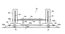
〔支持台車SV(図10、図11、図12)〕
支持台車SVは、図10に示す如く、車輪91を備えた車台90と、車台90の前後に取付けた角度調整枠93と、角度調整枠93間に張設したゴム板96と、ゴム板96の前後にゴム板露見部96を残して、ゴム板96の上面には支持プレート94を、下面にはステ−95を取付けたものであり、ステ−95の下端95が地面から浮上っており、角度調整枠93には、調整孔Ahを形成し、車台90の前後にはロープ固定環92があり、ロープ固定環92に牽引ロープ92aを取付け、マンホール(図示せず)から本管P内に入れて本管P内を移動させて取付管Pの補修施工に用い、施工作業終了後はマンホールから地上に回収するものである。
【0053】
内径250mmの本管Pに好適に適用出来る支持台車SVは、図11に示す如く、車台は全長L90が550mm、取付部90aの幅Waが80mm、連結部幅Wbが30mm、連結部長Lbが300mmであって、鋼板を円弧凹面に成形したものであり、前後取付部90aの下面の円弧凸面には、図11(C)の如く、左右一対の車輪91を円弧面から放射状に有し、中央の前後端部にはロープ固定環92を備えている。
また、角度調整枠93は、幅W93が50mm、径D93が180mmの金属製環状板体であって、車台90の取付部90aの凹曲面に固定したものであり、左右両側の各1/4周長に亘って、幅Wsが10mmのスリットSと、スリットSから切り込んだ幅Wgが10mmの溝g群を備えた長尺の調整孔Ahを備えたものである。
【0054】
また、図12に示す如く、ゴム板96は、幅W96が170mm、長さL96が520mmで、厚さt96が5mmであり、ゴム板96の両端には、幅W97が60mmの鋼製の上側取付プレート97Aと中央にボルト孔98hを備えた下側取付プレート97Bとを挟着してボルト99で固定し、ゴム板96の中央部には、幅W94が200mm、長さL94が300mmで10mm厚の木製の支持プレート94を上部に配し、下面には、支持プレート94の前部及び後部にステ−95を配し、支持プレート94とステ−95とでゴム板96をボルト99で挟着固定する。
【0055】
また、ステ−95は、図12(C)に示す如く、車台90を広く跨ぐように、ステ−下端95間を広くした2脚タイプとし、支持台車SVの移動時には、本管P内の土石と干渉しないように、図10の如く、ステ−下端95が地面より浮上った形態に配置する。
そして、ゴム板96の角度調整枠93への取付けは、ネジボルト98を前後の下側取付プレート97Bのボルト孔98h、及び角度調整枠93の調整孔Ahの溝gに挿通し、蝶ネジ98sで両端を固定する。
【0056】
従って、本実施例の支持台車SVは、本管P内の移動は、ステ−95が浮上ってステ−下端95が土石に干渉しないで平滑移動出来、支持プレート94に反転ゴムの膨出バルーン4Bの圧力が加われば、ステ−95の着地によって膨出バルーン4Bを定位置で支持出来、また、支持プレート94の角度変更は、両頭ネジボルト98の調整孔Ahの所望溝gへの変更取付けにより可能であり、本管Pの径寸法に応じて、支持プレート94の上下配置変更も、角度調整枠93の上部又は下部にネジボルト98の差渡し位置を変更することにより可能である。
【0057】
〔取付管Pの補修工程〕
補修施工は下記の1)から14)までの工程で実施する。尚、所要時間は、宅内汚水桝から本管への下水道取付管Pでの所要時間である。
1) まず、補修の必要な取付管Pの内周面を高圧洗浄により洗浄する(所要時間約5分)。
2) 次いで、洗浄済取付管内部の状況を調査する(所要時間約5分)。
3) 次いで、反転機1を現場に設置し、反転ガイド2、反転ゴム4及び反転ロープ11を準備し(所要時間約10分)、同時並行作業で補修材5に樹脂を含浸する(所要時間約20分)。
【0058】
4) 次いで、合成樹脂を含浸させた補修材5を反転ゴム4内に引込み反転ガイド2に装着し、同時並行作業で支持台車SVを調整して本管P内に入れる(所要時間約20分)。
5) 次いで、先端ガイド片24の先端2を位置決め設置する(所要時間約5分)。
6) 次いで、用意した慣用のエアーコンプレッサー(図示せず)からチューブtを介して先端ガイド片24と補修材5との間に高圧空気aを供給し、反転機1の本体ドラム内にも高圧空気Aを供給し、図16に示す如く、圧力計Mを見ながら反転ロープ11を徐々に巻戻し(矢印R)、チューブtから供給した高圧空気aで膨張した補修材先導部5で自力先行する補修材5と、高圧空気Aで加圧膨張した後方の反転ゴム4とを取付管P内へ反転進出させて、補修材5の全長が取付管P内に挿入され、外側フィルム52及び補修布材先端51が本管P内へ突出した状態を本管P内のテレビカメラが検出した状態で反転作用を一時停止する(反転の所要時間約10分)。
尚、補修材先導部5内への高圧空気aの供給は、反転ゴム4が反転開始して補修材5の内面に当接すれば供給不能となるが、その後、先導部5は高圧空気aの封入された状態を維持して補修材5を先導し、補修材先端5が挟圧中の反転ゴム4から突出した状態(図13)となれば、高圧空気aは外側フィルム52の裂け目C52から放出する。
【0059】
7) 次いで、図13の如く、予め取付管Pの傾斜角に調整した支持台車SVを、テレビカメラで目視しながら牽引ロープ92aによって補修管口PEに位置合せする(所要時間約5分)。
8) 次いで、再び反転ロープ11を徐々に緩め、反転ゴム4及び外側フィルム52を本管P内に出して、図14の如く、支持台車SV上の支持プレート94上に当接した段階で反転ロープ11を固定保持する(所要時間約5分)。
9) 次いで、反転ゴム4内の圧力を最大圧0.8kg/cmまで徐々に上昇させ、図1に示す如く、反転ゴム先端を外側フィルム52の裂け目C52から外側フィルム52を破って突出させ、反転ゴム先端には支持プレート94で支承された偏平形態の膨出バルーン4Bを形成して、管口PEから100mm突出した布材先端51を管口PE周囲へ鍔R状に押圧する(所要時間約5分)。
【0060】
10) 膨出バルーン4Bの形成と同時にバルブVを操作し、両側のゴム製の圧接板35によってゴム筒25を圧接して空密的に遮断した後、反転機1側の高圧空気を抜き、反転機1を開けて反転ロープ11を巻芯から外すと共に、カプラーCによって反転機1を第1ガイド片21から切離して反転機を撤去する(所要時間約10分)。
尚、切離した反転機1は次の現場へ移動し、前述の3)から9)までの工程遂行に使用する。
11) 補修材の硬化(所要時間約85分〜115分)
前述10)の工程で反転機1を切離し撤去した後も、反転ガイド2は、補修材5の合成樹脂が硬化するまでは反転作業時の状態を維持し続け、圧力計Mによって硬化処理中の反転ゴム4の内圧(補修材5への圧接力)を維持管理し、内圧降下に対しては調整バルブVからの高圧空気供給調整で対処する。
【0061】
補修材5が硬化すれば、12)管口切断(所要時間約10分)、→13)反転ガイド2の分解撤去及び管口仕上(所要時間20分)、→14)取付管内の補修状態調査確認(所要時間約10分)する。
1本の取付管Pの標準的な補修施工は、以上の1)乃至14)の工程で終了し、所要時間は約3時間である。
しかし、反転機1は、工程3)から工程10)まででのみ使用するだけであるので、1台の反転機1を複数個所へ移動使用出来、反転機の稼動率が従来の工法での使用に比して3倍以上に高まる。
【0062】
しかも、補修布材51が横メリヤス筒編物であるため、布材先端51が好適に拡開して鍔Rを形成し、管口PEのクラックKや隙間Kを完全に被覆し、内側フィルム53を短くして取付管Pの管口PEから管口PE周囲に亘る範囲を布材先端51のみで接着硬化したため、従来の別途施工で補修する管口PEの仕上げと同等、又はそれ以上の高品質の管口PEの更生補修となる。
そして、取付管Pの本体部と本管P内の管口PE部の補修施工が同時に実施出来るため、従来の本管P内側からの排水取付管口PEへの別途の施工が不要となる。
上述の施工順に従って略真直ぐな形態の取付管Pから略直角状屈曲部形態の取付管Pまでの種々の形態の下水道取付管に就いて試験施工を実施したところ、満足な結果が得られた。
【0063】
本実施例の施工にあっては、支持台車SVは、車輪91が車台90の円弧下面から放射状に配置されているため、車輪91が本管Pの底面の土石を避け、且つ、本管Pの円弧内面に略垂直に着地してスムーズに転がると共に、ステ−下端95も浮上って土石と干渉しないため、牽引ロープ92aを引張るだけで本管P内を水平姿勢でスムーズに移動し、所定位置で水平状態を維持する。
【0064】
また、補修材先端の外側フィルム延出部52には裂け目C52が存在するが、反転作用の初期は、補修材5の大部分は反転ゴム4で挟圧されて送り出されるため、チューブtから供給する高圧空気aによって補修材5の膨出先導部5が形成出来、外側フィルム延出部52の裂け目C52が反転ゴム4の挟圧から開放されるまで、即ち、補修材5の布材51の反転挿入終了の直前まで、先導部5(図16)が補修材5の反転をスムーズに遂行する。
そして、裂け目C52が反転ゴム4から突出した段階(図13)で高圧空気aが裂け目C52から出るが、以後の反転末期段階は、高圧空気Aによって取付管P周面に圧接して進行する反転ゴム4の作用により、補修材5は、布材先端51が本管P内に突出するまで取付管P内周に圧接引伸ばし作用を受け、補修材5の反転挿入が出来る。
【0065】
そして、図14に示す段階では、即ち、補修材先端5及び反転ゴム4の先端が支持台車SV上の支持プレート94に当接して反転ロープ11を固定した段階では、もはや外側フィルム52内には高圧空気aが存在せず、外側フィルム52は、反転ゴム4への高圧空気Aの加圧供給によって裂け目C52からきれいに破れ、反転ゴム4は、外側フィルム52から外側へ出てスムーズに膨出バルーン4Bを形成する。
従って、布材51の硬化処理完了後の、反転ゴム4の引抜き時に、外側フィルム52は、反転ロープ11と連なる接続紐12の引抜きによって硬化布材51からきれいに剥離出来る。
【0066】
また、反転ゴム4の先端の膨出バルーン4Bは、高圧の下での長時間(合成樹脂の硬化時間)維持となり、反転ゴム4の劣下を生じるが、支持プレート94を管口PEに略平行に保持して膨出バルーン4Bを均斉に偏平変形するため、比較的小径の膨出バルーン4Bでも布材先端51の管口PEへの鍔R形態での押圧が可能となり、消耗品である反転ゴム4の耐久性が向上し、管口PEを被覆する鍔Rも均斉に仕上がる。
【0067】
また、取付管口PEが本管Pの曲面に開口しているため、鍔Rは、本管Pの長手方向に長く、円周方向に短い外周楕円形態となるが、布材先端51を本管P内に100mm位突出させて補修すれば、図16に示すクラックK及び隙間Kの被覆は十分である。
しかも、補修材5の先端5側では、内側フィルム53が布材51より150mm短く、取付管口PEの50mm手前までであるため、布材先端51は、取付管口PEから本管P内面に亘るコーナーを屈曲して鍔Rを形成するため、鍔Rは、管口PEに対する接着硬化となり、強固なる補修鍔Rを形成する。
【0068】
〔変形例〕
補修材5は、実施例では、ゴム編みの横メリヤスパイル組織筒状布の布材先端51を内側フィルム53より突出させたが、補修材5の先端で布材51と内側フィルム53とを同長とし、補修布材先端51と管口PEとの間に内側フィルム53が存在しても、布材51は鍔R形態で硬化するため、更生補修管口PEとしては、クラックKや隙間Kを内側フィルム53を介して閉止出来、実用上は支障を生じない。
また、布材先端51は鍔R形態に拡開出来れば良く、従来のLIP工法等の補修布材の複数板重層タイプとし、先端51に拡開用の縦方向切れ目を散在させ、各切れ目が重ならないようにしても、本発明の実施が可能である。
また、実施例では、外側フィルム52の延出部52に縦方向の裂け目C52を設けたが、裂け目C52は反転ゴム4が膨出バルーン4B形成時に外側フィルム52を容易に破裂するためであるので、ミシン目又はピンホール等を設けても外側フィルム52の破裂は容易となり、外側フィルム52の材料を適切に選択すれば、裂け目C52等の破断部を設けなくとも本発明は実施可能である。
【0069】
また、実施例では、角度調整枠93は環状板体としたが、車台90の取付部90aの左側と右側に、一対の板状又はバー状片を平行立設して1つの角度調整枠とし、支持プレート94及びステ−95を備えたゴム板96を一対の立設枠間に慣用の係止スプリングで調整自在に張設しても良い。
この場合は、傾斜角変更による立設枠間の寸法変化にも係止スプリングの伸縮で対応出来、同時に、適用本管の内径変化に応じた支持プレート94の上下保持位置変化にも自在に対応出来る。
また、ステ−95を、例えば、望遠鏡式等、長さ変更可能に形成しておけば、本管Pの径変化に対応した支持プレート94の高さ位置調整が容易となり、ゴム板96の降下によるステ−95の着地保持作用が合理化出来る。
【0070】
また、支持プレート94及びステ−95は、実施例ではゴム板96に挟着固定したが、支持プレート94の下面に長短調整可能のステー95を固定し、支持プレート94の前部及び後部の左右両側端縁からフックを備えた引張スプリングを延出し、引張スプリングのフックを角度調整枠93の調整用孔Ahに調整自在に係止しても、所期の目的は達成出来、この場合は、支持プレート94の傾斜角調整、及び支持プレート94の本管Pの内径の変化に対応するステ−95の作用位置調整(長さ調整)も容易である。
【0071】
【発明の効果】
補修布材51を含む補修材5は、高圧流体の作用で反転進出する反転ゴム4と共に反転ガイド2から取付管P内へ連係して一緒に反転進出するため、補修更生対象の取付管Pが弯曲、或いは屈曲していても、反転ゴム4の反転挿入可能な取付管内へは機械的に挿通可能であり、しかも、反転ゴム4が寸法安定性に乏しい補修材5の挿入部分を順次拡開して取付管内周へ加圧して行くため、硬化補修材5は内周面が反転ゴム4の外周面によって平滑に仕上げられ、挿入部に補修材5内面に例え皺が発生していても、流水障害を生じない滑らかな状態に硬化処理出来る。
【0072】
また、補修材5も反転ゴム4と共に反転ガイド2に装着した状態で取付管Pを更生補修施工するため、補修施工の準備作業の全てが、補修対象取付管Pから離れた地上での作業となり、作業性及び施工性が向上する。
また、施工時には、反転ゴム4及び補修材5を装着した反転ガイド2の先端2を補修対象の取付管P入口部に近接配置出来るため、補修材5の必要材料長も補修対象取付管Pの必要補修長(取付管P長+鍔R長)と略同一と出来、従来の反転硬化法(LIP工法)の如き補修材の先端部と基部での長寸の切断廃棄部分が生じなく、補修材5及び使用硬化剤(含浸合成樹脂)の使用量が最少限に節約、合理化出来る。
【0073】
しかも、補修布材先端51を本管P内に突出した段階で、反転ゴム4の先端を支持プレート94に当接して加圧膨張させるため、膨出バルーン4Bは、比較的小径のバルーンを横方向拡開偏平形態とすることにより、補修布材先端51を管口PEに鍔R形態で当接出来、鍔Rの形成が、反転ゴム4の膨出負荷を抑制して合理的に実施出来る。
そして、鍔Rは取付管Pの管口PEを被覆当接して硬化するため、取付管Pから本管P内へと連なるクラックKも、取付管Pと本管Pとの取付部の隙間Kを閉止補修出来る。
【0074】
従って、本願補修方法の発明は、排水取付管Pの全長に亘る内周面と、取付管Pの本管Pへの取付部の取付管口PEとが同時に1本の補修布材51によって更生補修出来、従来の取付管の補修施工と、取付管補修施工後に別途実施する取付管Pと本管Pとの取付部の補修施工とが1本の補修材での1回の施工によって同時に実施出来、しかも、連続補修布材51による高品質な更生補修管が得られるものであり、排水取付管の画期的な補修手段の提供を可能とするものである。
【0075】
また、本願方法発明の実施に用いる支持台車SVは、支持プレート94を前後の角度調整枠93間に張設するため、各補修対象取付管P毎の本管Pへの取付角度の相違に対しても、支持プレート94が、補修対象取付管Pの取付角度に略平行形態に配置出来、支持プレート94によって支承される反転ゴム4の膨出バルーン4Bを均斉な偏平変形バルーン4Bと出来、最少限に抑制された膨出バルーン4Bによる補修布材先端51の均質確実な鍔Rの形成を可能とし、膨出バルーン4Bを高圧力で形成し、長時間維持する反転ゴムの劣下を最少限に抑制出来る。
【0076】
また、支持プレート94は下面にステ−95を浮上り状態で保持しているため、支持台車SVの本管P内での移動時は、ステ−95が本管P底面の土石の干渉を受けないで平滑に移動出来、支持プレート94が膨出バルーン4Bを支持する際は、ステ−95が降下着地して支持台車SVの移動変位を阻止し、膨出バルーン4Bの定位置での長時間支持が可能となる。
【図面の簡単な説明】
【図1】本発明の実施状態説明図である。
【図2】本発明に用いる反転装置の全体略示図である。
【図3】図2のA部拡大説明図であって、(A)は可撓ガイド片20を装着した状態図、(B)は可撓ガイド片20を除いた状態図である。
【図4】図2のクランプ手段C部の拡大説明図である。
【図5】図2のA部拡大分解説明図である。
【図6】本発明の要部説明図であって、(A)は反転ゴム取付状態図、(B)は(A)のB部拡大図、(C)は補修材先端5の取付状態説明図、(D)は補修材の取付状態外観図である。
【図7】補修材図であって、(A)は拡大部分断面図、(B)は注入パイプ57の配置を示す横断面図、(C)は合成樹脂含浸状態説明図である。
【図8】本発明に用いる反転機1の略示説明図である。
【図9】反転ガイドのバルブの図であって、(A)は縦断面図、(B)は横断面図である。
【図10】本発明支持台車SVの実施例の側面図である。
【図11】図10の分解部分説明図であって、(A)は平面図、(B)は側面図、(C)は部分斜視図、(D)は(C)のD部拡大図である。
【図12】図10の分解部分説明図であって、(A)は平面図、(B)は側面図、(C)は(B)の矢印C−C視図である。
【図13】本発明の支持台車SVを管口PEに対応配置した状態説明図である。
【図14】本発明の膨出バルーン形成開始状態説明図である。
【図15】本発明の補修材硬化後の反転ゴム4及び外側フィルム52の引抜き状態説明図である。
【図16】従来例図であって、(A)は反転作用説明図、(B)は反転終了状態説明図、(C)は更生補修済取付管口PEの説明図である。
【符号の説明】
1:反転機、 2:反転ガイド、
4:反転ゴム、 4B:膨出バルーン、
:反転ゴム基端、 4:反転ゴム先端、
5:補修材、 5:補修材基端、
:補修材先端、
7:第1接続管、 8:第2接続管、
9:弾性パイプ、 10:取付部材、
11:反転ロープ、 12:接続紐、
13:巻芯、 14:機台、
15:支持脚、 16:調節脚、
17:ハッチ、 18:供給口金、
19:接続口、 20:可撓ガイド片、
21:第1ガイド片、 22:第2ガイド片、
23:第3ガイド片、 24:先端ガイド片、
40:先端金具、 41:面板部、
42:止め環、 43:中空ボルト、
44:閉止ボルト、 51:補修布材(布材)、
51:布材先端、 52:外側シート(外側フィルム)、
53:内側シート(内側フィルム)、 55:テーブル、
56:絞りローラ、 57:注入パイプ、
71,81:係合環、 72,82:係止片、
71´,82´:突起、 74:嵌入部、
74´,81´:凹部、 84:嵌合部、
90:車台、 90a:取付部、
90b:連結部、 91:車輪、
92:ロープ固定環、 92a:牽引ロープ、
93:角度調整枠、 94:支持プレート、
95:ステ−、 95:ステ−下端、
96:ゴム板、 97A,97B:挟着板(取付プレート)、
98:ネジボルト(調整ボルト)、 98h:貫入孔、
98s:蝶ネジ、 99:締着ボルト、
A,a:高圧流体、 Ah:調整孔、
〜B:止具(バンド)、 C,C:クランプ手段、
C52:裂け目、 C93:環状板、
:第1取付位置、 F:第2取付位置、
g:溝、 K:クラック、
:隙間、 P:本管、
:排水取付管、 PE:取付管口(管口)、
R:鍔、 S:スリット、
SV:支持台車、 V:バルブ
[0001]
TECHNICAL FIELD OF THE INVENTION
The present invention relates to a method for repairing a drainage installation pipe connected to the ground from a sewage basin or rainwater basin of a factory or home and a repair device used for the method, and more particularly, to a repair apparatus installed in a factory or home. When a crack or breakage occurs in an existing buried drainage pipe connected to a sewer main from a sewage basin or rainwater basin, a repair material layer is stretched on the inner surface of the pipe without excavation without drilling. Technology for rehabilitation.
[0002]
[Prior art]
[Patent Document 1] JP-A-2001-30357
In each house, a house basin, that is, a sewage basin is installed, and the sewage basin and the sewer main under the road are connected by a drainage installation pipe buried underground, but the installation pipe is subject to aging. Due to aging, external loads, earthquakes, etc., breaks and seam breaks occur, resulting in inflow of groundwater and sediment, or outflow of sewage into the ground. Become.
[0003]
Conventionally, the most common method of repair and renovation of drainage attachment pipes connected from a house basin to a sewer main pipe is to dig a buried attachment pipe even if the attachment pipe is simply leaking due to cracks etc. This is an open-cut method in which existing installation pipes are removed and new installation pipes are installed and buried.
However, the excavation method in the city area is not preferable in terms of living environment, such as digging a road and adversely affecting traffic conditions and affecting nearby residents.
Therefore, in recent years, a non-cutting method instead of such a cutting method has been developed and put into practical use.
[0004]
As the non-cutting method, there is an inversion method of an IPC (Inversion Chemical Pipe) brease method or a LIP (Lateral in Pipe) method. In the IPC brease method, the reversal insertion of the repair material impregnated with synthetic resin is performed from the main pipe side to the mounting pipe side. This is done by compressed air, hot water is injected into the repair material, and the repair material is hardened. In the LIP method, the end of the repair material is attached on the wastewater basin side of the house, and the existing repair pipe is repaired by compressed air. After the material is inserted upside down and the repair material is cured, the parts protruding into the main pipe and the sewage basin are cut and removed.
[0005]
The inventor of the present invention has proposed a novel method of repairing drainage pipes that is completely different from the IPC brease method and the LIP method as Japanese Patent Application No. 2000-309158 (Japanese Patent Application Laid-Open No. 2001-30357).
That is, the proposed invention is shown in FIG. 16, in which the repair material 5 impregnated with the curable synthetic resin is connected to the reversing rubber 4 and the connecting cord 12 and is mounted together in the reversing guide 2, and the high-pressure fluid A, the reversing rubber 4 and the repair material 5 are both connected to the drainage pipe P by the reversing rope 11 while supplying A. 1 Into the mounting pipe P with the cloth material 51 of the repair material 5 as shown in FIG. 1 The cloth material 51 as a repair material is subjected to hardening treatment in a state where the inner surface of the drainage pipe is covered and pressed, and as shown in FIG. 1 Is rehabilitated and repaired by the hardening tube layer of the cloth material 51.
[0006]
[Problems to be solved by the invention]
In the epoch-making drainage pipe repair method of FIG. 16, the repair material 5 is cured while the reversal rubber 4 is pressed against the repair material 5, so that the inner surface of the rehabilitation pipe layer formed by the cloth material 51 is exposed to running water. Wrinkles that cause trouble are not generated, and the surface is smooth. In addition, it is possible to perform repair work on all the mounting pipes of the reversible rubber 4 that can be inverted and inserted. Therefore, it is extremely excellent.
[0007]
However, as shown in FIGS. 1 Since the new rehabilitation pipe layer is formed by the cloth material 51 on the inner peripheral surface of the drainage pipe P 1 At the pipe opening PE, the mounting pipe P 1 Main P from inside 0 Crack K that reaches inside 1 And mounting pipe P 1 And the main P 0 Gap K at the connection with 2 Cannot be repaired.
And crack K 1 And gap K 2 Exists in the main pipe of rainwater, groundwater, earth and sand from the stratum around the mounting pipe. 0 If necessary, separate the main pipe P 0 It is necessary to repair around the mounting port PE with another repair material from the inside.
The present invention is an epoch-making improvement of the repair method shown in FIG. 16, and is implemented by using one repair cloth material 51 when implementing the invention of Japanese Patent Application No. 2000-309158 (Japanese Patent Application Laid-Open No. 2001-30357). At the same time as the rehabilitation repair of the inner peripheral surface of the pipe, the periphery of the mounting port PE can be repaired.
[0008]
Means and Action for Solving the Problems
As shown in FIGS. 1 and 2, for example, the repair method invention of the present application is a method of inverting a repair material 5 including a tubular repair cloth material 51 impregnated with a synthetic resin and a tubular reversal rubber 4. The reversing rubber 4 and the repairing material 5 are attached from the reversing guide 2 to the drainage pipe P by being mounted in the guide 2 and acting on the reversing rubber 4 by the high-pressure fluid A. 1 Inwardly, the repair material 5 is inserted in a reverse direction so that the repair material 5 is outside the reverse rubber 4, and the repair cloth material tip 51 is inserted. E (Fig. 13) 0 Into the main pipe P 0 The inflatable balloon 4B is formed at the tip of the reversal rubber 4 by pressing and inflating the support plate 94 disposed therein, and the repair material 5 is attached to the mounting pipe P. 1 While pressing against the inner peripheral surface, the repair cloth material tip 51 E Is the mounting pipe P 1 In this state, the impregnated synthetic resin is cured in a state in which the impregnated synthetic resin is spread and pressed in the form of a flange R covering the opening PE, and after the repair cloth material 51 is cured, the reversing rubber 4 is pulled out, and the reversing guide 2 is separated from the repair material 5.
[0009]
As the repairing material, a conventional repairing material that can freely deform in the length direction and the radial direction can be used. E Can be used as a knitted fabric structure that can be expanded and deformed into a flange R shape, or as a multi-layered form of cloth with a cut for expansion. It is a tubular knitted fabric having a horizontal knitting spir structure comprising:
Further, as shown in FIG. 1, the inflated balloon 4B has a repair cloth tip 51. E May be pressed to the outside of the pipe opening PE in the form of a flange R, and the deformed form of the bulging balloon 4B by the support plate 94 may be changed to the repair cloth material tip 51. E May be determined in accordance with the size of.
The connection between the cylindrical repair material 5 and the cylindrical reversing rubber 4 is only required when the reversing rubber 4 is inverted and inserted together with the reversing material 5. E Is held by the reversing guide, and the repair cloth material tip 51 is E Should just be drawn inside the reversing rubber 4.
Further, the support plate 94 supports the bulging of the head of the reversing rubber 4 so that the bulging balloon 4 </ b> B E The balloon 4B may be regulated so as to press the main tube P into the main opening P. 0 The plate material placed and fixed in the main pipe P 0 It may be a plate mounted on a chassis that can be moved inside.
[0010]
In addition, here, "Mounting pipe P 1 '' Is the surface of the ground, such as the installation pipe connected to the sewer main from the house basin, the drainage installation pipe connected from the rainwater basin of the home or factory to the sewer main, and the drainage installation pipe from the wastewater treatment basin of the factory. Underground drainage main pipe P from the installed sump (basin) 0 The underground mounting pipe connected to the (sewer main pipe) broadly means “reversed rubber”, which can be used to form a bulging balloon 4B such as synthetic rubber, natural rubber, or a sheet material having rubber elasticity. The term “synthetic resin” broadly refers to a synthetic resin that undergoes light curing, heat curing, and natural curing (curing over time), and the “fluid” refers to air, heated or water at room temperature. , Gas and the like.
[0011]
Therefore, the repair material 5 is transferred from the reversing guide 2 to the mounting pipe P together with the reversing rubber 4 subjected to the high-pressure fluid action. 1 Since the reversible rubber 4 is inserted together in a reverse direction, the reversible rubber 4 can be inserted in all places where the reversible insertion is possible. 1 Even if it is curved or bent, the mounting pipe P of the repair material 1 Insertion arrangement in the interior is possible.
Further, since the repair material 5 having poor dimensional stability is inverted to the outside of the inverted rubber, the inverted insertion portion of the repair material is sequentially turned on by the expansion pressure of the inverted rubber 4 so that the mounting pipe P 1 It is pressed by the inner peripheral surface, and the mounting pipe P 1 The generation of wrinkles of the repair material at the bent portion is minimized, and even if a slight wrinkle is generated, the inner peripheral surface of the repair material 5 abutting against the reversal rubber 4 by pressing the reversal rubber 4 does not hinder the flow path. It becomes a smooth surface of a degree.
[0012]
Further, the reversing insertion of the repair material 5 is performed by connecting the tip of the reversing guide 2 to the mounting pipe P 1 The required length of the repair material 5 is the mounting pipe P to be repaired. 1 It can be set according to the length of the material, and there is no long cut waste at the tip and base of the repair material as in the conventional reverse hardening method (LIP method), and the use of materials such as repair material and synthetic resin is rationalized. I can do it.
Further, the preparation work for the reverse insertion of the repair material 5 is performed by the mounting pipe P to be repaired. 1 Since it can be carried out on the ground away from the sea, construction preparation work can be streamlined.
[0013]
Moreover, the repair cloth material tip 51 E To the main P 0 The protruding balloon 4B has a relatively small-diameter balloon in the form of a flattened laterally-expanded flat cloth so that the distal end of the reversing rubber 4 abuts on the support plate 94 and pressurizes and expands when the protruding rubber is protruded inward. Material tip 51 E Can be brought into contact with the pipe opening PE in the form of a flange R, and the formation of the flange R can be rationally performed while minimizing the load on the inverted rubber.
And the flange R is the mounting pipe P 1 In order to harden by contact with the pipe opening PE, the mounting pipe P as shown in FIG. 1 From main P 0 Crack K that leads to 1 And mounting pipe P 1 And the main P 0 And the clearance K between the mounting part 2 The repair of the present invention can be performed simultaneously with the repair of the inner peripheral surface of the mounting pipe, as well as the repair of the mounting pipe opening PE, which could be conventionally performed only by a separate construction.
Therefore, according to the present invention, the mounting pipe P 1 And the mounting pipe P 1 Main P 0 At the same time, the rehabilitation repair can be performed by the repair cloth material 51 on the pipe port PE of the attachment portion to the drainage pipe, and it is possible to provide an innovative repair means for the drainage attachment pipe.
[0014]
Further, in the invention of the repair method of the present application, the reversing operation of the reversing rubber 4 is stopped in a state where the reversing rubber 4 is in contact with the support plate 94, and then only the pressure of the high-pressure fluid A in the reversing rubber 4 is increased. It is preferable that the tip of the reversing rubber 4 is a flattened balloon 4B deformed between the support plate 94 and the pipe opening PE.
The support plate 94 is, as shown in FIG. 0 The repair cloth material tip 51 E Is the main P 0 The reversing operation may be interrupted at the stage where the support plate 94 is exposed, and the support plate 94 may be arranged at the mounting port PE.
In addition, since the reversing rubber 4 fixes the protruding length of the tip by abutting on the support plate 94, the swelling load of the reversing rubber 4 can be suppressed to a degree necessary for forming the flange R.
[0015]
Accordingly, since the reversing action of the reversing rubber 4 is stopped in a state where the reversing rubber 4 is in contact with the support plate 94, the amount of protrusion of the tip of the reversing rubber 4 can be minimized, and the bulging balloon regulated by the support plate 94. 4B, the repair cloth tip 51 E And a relatively small flattened balloon 4B in which the swelling load of the reversing rubber 4 is regulated, and the repair cloth material tip 51 can be pressed. E It is possible to form the flange R required for covering the pipe opening PE in the step (a).
[0016]
In the invention of the repair method of the present application, the support plate 94 is attached to the mounting pipe P. 1 It is preferable to dispose them substantially parallel to the port PE.
In addition, the meaning of “substantially parallel to the mouth PE” means that the virtual plane of the mouth PE and the support plate 94 are substantially parallel, and the mounting mouth PE is inclined with respect to the ground and the main pipe P is inclined. 0 Opening means that the support plate 94 is also inclined.
Therefore, since the support plate 94 is disposed substantially parallel to the mouth PE, the flattening deformation of the swelling balloon 4B at the tip of the inverted rubber 4 by the support plate 94 becomes uniform with respect to the mouth PE, and a relatively small bulge balloon is formed. Even if it is 4B, the cloth material tip 51 E The reason is that the uniform formation of the flange R can be rationally performed, and the durability of the reversible rubber 4 which is apt to deteriorate and to be easily damaged is improved.
[0017]
In addition, the base 5 of the repair material 5 E To the tip 2 of the reversing guide 2 T Of the repair material 5 T Is pulled into the reversing rubber 4 and the connecting string 12 T To the reversing rope 11, which is unwound from the winding core 13 of the reversing machine 1. T And a drainage pipe P from the reversing guide 2 of the reversing rubber 4 1 It is preferable that the repair material 5 be turned over and extended outside the inverted rubber 4.
In this case, the connecting cord 12 and the repair material tip 5 T Can be implemented by a temporary fixing that is weak enough to be released by the pulling action of the reversing rubber 4.
[0018]
Therefore, the repair material base 5 E Is the tip 2 of the reversing guide 2 T Of the reversing guide 5 of the repair material 5 T The reversing action of the reversing guide becomes smooth, T Is the mounting pipe P 1 In this case, the length of disposal of the repair material 5 after repair can be reduced to a minimum and the material used can be rationalized.
Furthermore, the repair material tip 5 T And inverted rubber tip 4 T Since the connecting cord 12 is present between them, the work of inserting the repairing material 5 into the reversing rubber 4 becomes easy by pulling the connecting cord 12, and the mounting of the repairing material 5 and the reversing rubber 4 into the reversing guide 2. Work is also easy. Then, the reversing rubber 4 is attached to the mounting pipe P by the entire length of the repair material 5. 1 Repair material tip 5 even after inverted insertion into T Can be inverted and the bulging balloon 4B at the tip of the inverted rubber can be selectively formed. By applying pressure over the entire length of the repair material 5 including the flange R portion, the mounting pipe P of the repair material 5 can be formed. 1 Press hardening of the entire inner peripheral surface and the flange R of the mounting pipe opening PE can be uniformly performed.
[0019]
Further, it is preferable that the repairing material 5 includes at least three layers of the cloth material 51 impregnated with the synthetic resin, the outer sheet 52, and the inner sheet 53 in a free multilayer form.
If the cloth material 51, the outer sheet 52, and the inner sheet 53 are in the loose form, the impregnation work of the synthetic resin liquid into the repair material 5 is easy as shown in FIG. 1 Abutment adaptability to the inner peripheral surface and cloth material tip 51 E This also improves the contact with the pipe opening PE in the form of the flange R, and also makes it easy to peel off the sheet 52 (the outer sheet is inverted) of the inner peripheral surface after the curing treatment.
[0020]
The cloth material 51 preferably has a thickness that is easy to impregnate and hold the synthetic resin and is deformable, that is, a horizontal knitted fabric that is easy to change in diameter and length (change in length and width) is preferable. The sheet 53 may have a function of retaining the synthetic resin liquid during the construction process. 1 The inner sheet 53 abutting on the inner peripheral surface is still attached to the mounting pipe P even after the repair. 1 Since it remains between the inner peripheral surface and the repair cloth material 51, the mounting pipe P 1 A water-resistant film exhibiting a function of closing water leakage from the pipe is preferable. If a rubber sheet is applied, small vibration stress to the repair and rehabilitation pipe layer 51 due to a small earthquake or the like is also appropriately absorbed and the repair mounting pipe P is used. 1 It is preferable because a function of protecting the same can be expected.
Further, since the outer sheet 52 becomes inside the repair cloth material 51 by reversing, it is preferable that the outer sheet 52 can be peeled and fractured together with the pull-out of the reversal rubber 4 after the repair.
Typically, for both the outer sheet and the inner sheet, a thin, water-impermeable synthetic resin film is suitable from the viewpoint of construction and availability.
[0021]
Further, the outer sheet 52 of the repair material 5 has an extension 52 T The cloth material 51 is provided with T From the repair material tip 51 E Are preferably projected.
In this case, the extension 52 of the outer sheet T Only to the connecting cord 12 to fix the repair material tip 5 T Inverted rubber tip 4 T Can be connected, and the outer sheet 52 existing on the inner surface of the cured repair material 5 can be peeled off and removed from the repair cloth material 51 with a small pulling force by the pull-out action of the inverted rubber 4 after the repair material 5 has been cured. Part 52 T The temporary fixation and separation of the repair material 5 from the reversal rubber 4 are facilitated by the presence of.
And the extension part 52 T Is only the outer sheet 52, which is inside the cloth material 51 by the reversing action of the reversing rubber 4, so that when the bulging balloon 4B of the reversing rubber 4 is formed, it is broken by the expanding action of the reversing rubber 4. At the time of pulling out, the connecting cord 12 can be separated and removed without any trouble.
[0022]
The extension 52 of the outer sheet 52 T 6D, it is preferable to form a longitudinal tear C52 as shown in FIG.
In this case, when forming the bulging balloon 4B with the tip of the reversing material 5 and the reversing rubber 4 after the reversing operation of the reversing rubber 4, the outer sheet 52 can be smoothly split from the predetermined position in the longitudinal direction by the reversing rubber 4 in the longitudinal direction, Since the outer sheet 52 ruptured by the bulging balloon 4B is connected to the connecting cord 12, the outer sheet 52 is detached and removed by the connecting cord 12 due to the pull-out of the reversing rubber 4 after the curing process of the flange R, It can be implemented smoothly.
[0023]
In addition, the inverted rubber base end 4 E And repair material base 5 E Are held airtight against the reversing guide 2, and the leading portion 5 of the repairing material 5 during reversal is L It is preferable that the repair material 5 be invertedly inserted with the inverted rubber 4 in a state where the pressure of the high-pressure fluid a is applied.
Replacement material 5 with tip 5 T When the reversing material 4 is inserted in a reversed state with the reversing rubber, there is a danger that the repair material 5 may be wrinkled due to the right-angled bending angle of the inner surface of the mounting pipe and small friction protrusions. However, as shown in FIG. Inversion leader 5 L The repair material 5 itself is also inserted in the mounting pipe P in the same manner as the reversible rubber, because the reversing rubber 4 is lead-inserted in the reversal rubber 4 while applying the pressure of the high-pressure fluid a to the 1 Irrespective of the corners or small projections inside, it is possible to smoothly and reversibly insert it in an expanded form, so that the repair material 5 can be attached to the mounting pipe P without wrinkles. 1 Can be inserted upside down into the repair cloth material tip 51 E Main P as designed 0 It can protrude inward, and eventually the mounting pipe P 1 Irrespective of the shape of the inner peripheral surface, it is possible to repair the inner surface of the mounting pipe smoothly and uniformly repair the flange R of the mounting pipe opening PE.
[0024]
Further, a valve V for shutting off the flow path is disposed in the flow path of the reversing guide 2 for supplying the high-pressure fluid A from the reversing machine 1 to the reversing rubber 4, and the reversing rubber 4 reversely inserts the entire length of the repairing material 5 to attach the mounting pipe. P 1 The inner peripheral surface is pressed and pressurized, and the tip of the repair cloth material 51 is bulged with the balloon 4B at the tip. E It is preferable that the valve V cuts off the flow path of the reversing guide 2 at the stage where the reversing guide 4 is pressed against the pipe opening PE in the form of a flange R, and the repair material 5 is cured while maintaining the high pressure expansion state of the reversing rubber 4.
[0025]
In this case, the reversing machine 1 does not need to operate for applying pressure during the flow path blocking operation of the valve V, and therefore, the hardening work of the repair material 5 which requires a relatively long time (natural hardening: 85 to 115 minutes) During ()), the reversing machine 1 can be stopped, so that the operating energy of the reversing machine can be saved by the valve action, the reversing machine can be prepared for the next operation, or the reversing guide 2 during the curing operation can be used. It is also possible to disconnect the reversing machine from the machine and move it to the next site to operate it, so that the operation rate of the reversing machine, which requires equipment costs, can be improved, and the drainage pipe P 1 Economical and rational construction of repair work becomes possible.
[0026]
Also, the valve V includes a rubber cylinder 25 provided in the flow path of the reversing guide 2 and pressure contact means 33, 34, 35 of the rubber cylinder 25. 0 It is preferable to provide a tube t1 for adjusting the high-pressure fluid through the tube.
In this case, since the valve V can be closed only by pressing the rubber cylinder 25 from both sides, for example, as shown in FIG. It can be easily implemented with simple valve opening and closing means.
Moreover, the rubber cylinder 25 as a consumable can be air-tightly mounted only by tightly tightening the rubber cylinder 25 to the reversing guide ends on both sides separated for mounting the valve with a band. Replacement becomes easy.
[0027]
The valve V has a pressure gauge M and an adjustment valve V. 0 Is provided to detect the pressure on the downstream side (pressure maintaining side) of the valve V, and when the pressure decreases, the adjustment valve V 0 By adding the pressure fluid A1 via a tube t1 from a conventional pressure device for replenishing the pressure fluid from the pressure source, the high pressure state of the inflated balloon 4B can be maintained, and a slightly rough valve V that causes a slight pressure leak can be employed. This is advantageous from the viewpoint of the production of the valve and from the viewpoint of the operation.
[0028]
Further, as shown in FIG. 10, a support truck SV for use in carrying out the invention of the repair method of the present application is provided with wheels 91 and has a pair of angle adjusting frames 93 at front and rear portions of a chassis 90 which can be moved back and forth by a rope 92a. And a support plate 94 provided with a stay 95 on the lower surface is stretched between the front and rear angle adjustment frames 93, and the stay 95 lands by the pressure drop of the support plate 94, thereby preventing the movement of the chassis 90. Structure.
[0029]
The angle adjustment frame 93 is provided so that the support plate 94 can appropriately support the bulging balloon 4B at the tip of the reversing rubber 4 so that the drainage mounting pipe P can be used. 1 Of main port P of PE 0 The support plate 94 can be provided with inclination adjustment with respect to the chassis 90, that is, with respect to the horizontal plane, in accordance with the connection angle to the support plate 94. Therefore, the support plate 94 may be attached so that the angle can be adjusted. Normal drainage installation pipe P if the angle can be adjusted from 0 ° (horizontal) to 45 ° left and right 1 Can be repaired.
When the support plate 94 is in a free state, that is, in a no-load state, the stay 95 has a lower end 95. E May protrude slightly downward from the lower surface of the undercarriage 90. E May be determined.
Further, the support plate 94 may be attached to the angle adjustment frame 93 at both front and rear ends in a form having a spring elasticity such as a rubber plate or a spring.
[0030]
In the support cart SV of the present invention, the support plate 94 is provided with the drainage pipe P 1 To be installed under the angle adjustment corresponding to the installation angle of the opening PE 1 The support plate 94 can be arranged in parallel with the pipe opening PE surface according to the condition, and the bulging balloon 4B formed on the head of the reversing rubber 4 can be rationally and properly repaired. E The support plate 94 can be arranged so that a uniform flange R can be formed around the pipe opening PE.
[0031]
When the balloon 4B presses the support plate 94, the lower end of the stay 95 E Is landed to prevent the movement of the support cart SV, and the repair cloth material tip 51 by the bulging balloon 4B is used. E The pressing state for a long time during the curing process in the form of the collar R can be appropriately maintained, and the curing process of the collar R can be performed with high quality.
Moreover, when the support plate 94 is in the free state, the stay 95 is at the lower end 95. E Is in a state of floating above the ground. 0 Movement within the stay lower end 95 E Is the main P 0 It can be carried out smoothly with only wheels without being disturbed by debris at the bottom.
[0032]
Further, in the support cart SV of the present invention, a rubber plate 96 is stretched between the front and rear angle adjustment frames 93 so as to be elastically displaceable, and the support plate 94 and the stay 95 are sandwiched and fixed to the rubber plate 96. Is preferred.
In this case, the front end and the rear end of the rubber plate 96 are attached to the angle adjustment frame 93, and the elastic displacement region 96 of only the rubber plate is provided between the front and rear angle adjustment frame 93 and the front and rear ends of the support plate 94. F The desired function can be provided to the support plate 94 and the stay 95 only by forming the rubber plate 96 as shown in FIG. F Can be clamped and fixed between the upper support plate 94 and the lower stay 95 with a fastening bolt or the like, so that the production of the support trolley SV is simple and easy.
[0033]
Further, a pair of front and rear angle adjustment frames 93 are provided with adjustment holes Ah on both left and right sides, and front and rear end portions 96 of the rubber plate 96. E Preferably, the left and right ends of the rubber plate 96 are selectively fixed to the adjustment holes Ah so that the angle of the rubber plate 96 with respect to the chassis 90 can be adjusted.
In this case, the left and right ends of the front and rear ends of the rubber plate 96 and the adjustment holes Ah of the angle adjustment frame 93 may be fixed with conventional fastening bolts, locking pins, and the like. However, as shown in FIG. 12B, a clamping plate (mounting plate) 97B having a bolt hole 98h is fixed, and one adjustment bolt ( It is preferable to insert a screw bolt (98).
Therefore, the front and rear end portions 96 of the rubber plate 96 E The support plate 94 can be set at an inclination angle corresponding to the inclination of the mounting port PE by simply selecting and fixing the support plate 94 to the angle adjustment frame 93, and the rubber plate 96 can be easily attached and detached. It is easy to adjust the inclination of the rubber plate, and it is easy to replace the rubber plate as a consumable.
[0034]
In addition, in the support cart SV of the present invention, as shown in FIG. 11, the angle adjustment frame 93 is an annular plate C93, and includes a group of slits S and a group of cut grooves g with approximately 1/4 circumferential length on both left and right sides. Equipped with adjustment hole Ah, rubber plate end 96 E It is preferable to lock the adjustment bolt 98 penetrating into the adjustment hole Ah.
Since the angle adjustment frame 93 is an annular plate that is advantageous for imparting mechanical strength, it can be made of a relatively thin steel plate, and the angle of the support plate 94 can be adjusted by adjusting the position on the adjustment hole Ah of the symmetrical circular arc. Because of the change, the inclination angle can be easily adjusted, and the adjustment bolt 98 is slid in the slit S by pulling the rubber plate 96 of the support plate 94 or a mounting elastic member such as a spring, so that the adjustment bolt 98 is re-inserted into the predetermined cut groove g. The fitting allows easy adjustment of the angle of the support plate 94.
[0035]
Further, in the support cart according to the present invention, the chassis 90 includes a wide mounting portion 90a at the front and rear portions, and a narrow connecting portion 90b between the mounting portions 90a. It is preferable to straddle 90b widely.
In this case, if the connecting portion 90b and the mounting portion 90a connected to the front and rear thereof are formed as upwardly concave concave plates as shown in FIG. 11, the annular plate C93 can be easily fixed and sufficient mechanical strength can be obtained even with a relatively thin steel plate. This is advantageous in that the target strength is obtained.
Therefore, since the stay 95 straddles the connecting portion 90b widely, the required tilting rotation of the stay 95 by adjusting the angle of the support plate 94 can be performed without interference with the connecting portion 90b of the chassis.
[0036]
BEST MODE FOR CARRYING OUT THE INVENTION
The case where the present invention is applied to a sewer attachment pipe embedded and connected to a sewer main pipe from a domestic wastewater basin will be described in detail.
The sewerage pipe P 1 When the repair and rehabilitation work is carried out, first, the construction site and the obstacles are checked using a TV camera as a preparatory surveyor, and after the removal of obstacles and the like as a preparatory work is completed, FIG. As schematically shown in FIG. 1, a repair device including a reversing machine 1, a reversing guide 2 connected to the reversing machine 1, and a reversing rubber 4 which is protruded and retracted from the reversing guide 2 by a reversing rope 11 wound up and rewound by the reversing machine 1. Using a conventional compressor for supplying the high-pressure fluid A to the reversing machine 1, the repair material 5 selected and prepared based on the preliminary investigation is mounted on the reversing guide 2 of the apparatus, and the repair target is mounted by the reversing rubber 4. Pipe P 1 The repair material 5 is inserted into the inside upside down.
[0037]
Next, the repair cloth material tip 51 E Is the main P 0 With the main pipe P 0 The inflatable rubber tip is pressed against the support plate 94 correspondingly disposed therein to form the bulging balloon 4B, and the repair cloth material tip 51 is formed by the balloon 4B. E Is deformed into a flange R shape, pressed against the mounting port PE, and the mounting pipe P 1 Pressure hardening of the inner peripheral surface and the port PE is achieved, and the reversal rubber 4 is attached to the mounting pipe P. 1 The inside of the repaired material is extracted from the inside and the entrance end of the repaired material is treated to complete the repairing work.
[0038]
[Reversing machine (Fig. 8)]
The reversing machine 1 is employed in the embodiment of the invention of Japanese Patent Application No. 2000-309158, and has a main body in the form of a drum having a pressure-resistant airtight structure, and as shown in FIG. The platform 14 is supported by supporting legs 15 and adjusting legs 16, and an opening / closing hatch 17 for work and a supply base 18 for connecting to a compressor (not shown) are provided on an upper portion, and a reversing guide 2 is connected in front. The main body has a winding core 13 which is rotated by an outer handle (not shown) inside the main body. The mouth 19 has a structure in which the position can be adjusted up and down. In addition, a coupler C is provided at the end of the connection port 19. 0 To facilitate attachment and detachment with the base end of the reversing guide 2.
In addition, since the machine base 14 has the wheels W and the stays Y, when moving, the front stays Y are lifted and moved by the wheels W, and if installed at the site, the stays Y prevent the reversing machine from moving. Things.
[0039]
[Reversing guide]
The reversing guide is also employed in the practice of the invention of Japanese Patent Application No. 2000-309158, and the entire structure of the reversing guide 2 is a first guide for connecting from the reversing machine 1 side to the connection port 19 of the reversing machine 1. The first guide piece 21, the second guide piece 21, the second guide piece 22, the curved third guide piece 23, the flexible guide piece 20, and the curved tip guide piece 24 are removably connected to each other. The piece 22, the third guide piece 23, and the tip guide piece 24 are lightweight metal pipes having the same diameter (140 mm diameter), and the flexible guide piece 20 is a sunny pipe (trade name).
[0040]
Then, as shown in FIG. E Is the coupler means C on the connection port 19 of the reversing machine 1. 0 And a structure in which a valve V is interposed between the second guide piece 22 and the third guide piece 23 for attachment and detachment (FIG. 9). As shown in FIG. Clamping means C is provided at the lower end of the guide piece 23. 1 The first connection pipe 7 is connected via a hollow to the outer periphery of the first connection pipe 7 and the upper end of the flexible guide piece 20 is attached to the band B 2 As shown in FIG. 3, the lower end of the flexible guide piece 20 is attached to the upper end of the hollow second connection pipe 8 by a band B. 3 As shown in FIG. 2, the lower end of the second connecting pipe 8 is 2 It is a structure to connect with.
[0041]
Clamping means C 1 As shown in FIG. 4, an engagement ring 71 is screwed to the lower end of the third guide piece 23. 1 , S 2 And the fitting portion 74 at the upper end of the first connection pipe 7 is fitted into the engagement ring 71 to abut the packing 71 ′, and the projection 72 ′ is rotated by the rotation of the locking piece 72 on the engagement ring. Is fitted and stopped in the recess 74 ′ on the fitting portion 74 of the first connection pipe 7.
Further, the clamping means C 2 As shown in FIG. 5, as shown in FIG. 3 , S 4 The engagement ring 81 is fitted into the fitting portion 84 at the lower end of the second connection pipe 8, and the upper end of the engagement ring 81 is brought into contact with the packing 84 ′ of the fitting portion 84, and the engagement on the fitting portion 84 is stopped. In this structure, the projection 82 ′ is fitted and locked in the recess 81 ′ on the locking ring 81 by the rotation of the piece 82. That is, the clamping means C 1 And clamping means C 2 In both cases, one-touch attachment / detachment can be made by manually raising and lowering the locking pieces 72 (82).
[0042]
In addition, the tip guide piece 24 has a base t 0 And a tube t from a pressurized fluid supply device (not shown) is 0 To supply the high-pressure fluid a (FIG. 16) to the inner peripheral surface of the distal end guide piece 24, and the base 5 E A fastening groove M for facilitating airtight tightening is arranged.
As shown in FIG. 2, an elastic pipe 9 made of rubber is attached to the first connection pipe 7, and the inside of the flexible guide piece 20 is hung down. E The mounting member 10 for mounting can be tightened.
The tip guide piece 24 is provided with various mounting pipes P. 1 In order to be able to attach the repair material 5 of various diameters corresponding to the inner diameter, T (For example, 75 for the mounting pipe diameter 100, 130 for the mounting pipe diameter 150, and 170 for the mounting pipe diameter 200) are prepared.
[0043]
[Valve V (FIG. 9)]
As shown in FIG. 9, the valve V covers the rubber tube 25 by covering a rectangular tube cover 31 formed by welding with an iron plate from the end of the second guide plate 22 to the end of the third guide plate 23 by the mounting piece 32. Attach. A reinforcing plate 31 'is reinforced at an intermediate portion of the cover 31, and guide nuts N are fixed to the reinforcing plates 31' on both sides, and each screw rod 34 is screw-fitted into each guide nut N. A rubber square pressure plate 35 having a thickness of 3 cm, a width of 2.5 cm and a length substantially equal to the vertical length of the inner surface of the cover 31 is attached by a conventional means so that the rotation of the screw rod 34 is not transmitted. A pulley 33 having a handle 33 'is fixed to the outer base end.
[0044]
Then, guide plates G are fixed to the four inner corners of the cover 31 in such a manner that the press contact plates 35 are sandwiched from both sides. That is, when the handle 33 'is rotated, the screw rod 34 is guided and guided by the guide nut N, and each press-contact plate 35 can move forward or backward while being guided by the upper, lower, left and right guide plates G in the cover 31. Of the rubber cylinder 25 can be pressed from both sides by the inwardly protruding action of the pressure contact plate 35.
Instead of the guide plates G at the four corners of a total of eight plates, up, down, left and right, guide grooves may be formed on the inner surface of the cover 31 so that both ends of the press contact plate 35 slide in the guide grooves.
[0045]
Further, the inside of the rubber cylinder 25, the pressure gauge M and the adjustment valve V 0 Is a communication type, and when the pressure gauge M detects a pressure drop inside the rubber cylinder 25, the adjustment valve V 0 Can be opened to add a high-pressure fluid (air) from a high-pressure source (not shown) to restore the pressure inside the rubber cylinder 25 to a desired value. 0 Is open, the high-pressure fluid (air) in the rubber cylinder 25 can be discharged.
[0046]
[Installation of the reversing rubber 4 (FIGS. 2, 3, and 6)]
The reversing rubber 4 is a rubber tube having a diameter smaller than the inner diameter of the reversing guide 2, E Is attached to the mounting member extending into the flexible guide piece 20, and the tip 4 T To the inverted rope 11.
That is, as shown in FIG. 2 and FIG. 1 A rubber tube thicker and less elastic than the reversing rubber 4 is provided on the outer periphery of the distal end of the first connection pipe 7 which is detachably attached to the lower end of the third guide piece 23 and is made of a metal tubular member having substantially the same diameter as the third guide piece 23. Base end 9 of elastic pipe 9 made of E Screw band B 5 (FIG. 3), and the distal end of the elastic pipe 9 is connected to the base end 10 of the hollow mounting member 10 made of a plastic molded body. E Screw band B airtight on top 6 Fasten with.
[0047]
Then, the base end 4 of the reversing rubber 4 inserted into the reversing guide 2 E The mounting member tip 10 T (FIG. 3) and bent outward from the screw band B 4 And tightly tighten the rubber tip 4 T Has a screw hole H in the center as shown in FIG. 0 A fixed band is airtightly fastened to the outer periphery of a cylindrical tip fitting 40 having a 50 mm diameter face plate portion 41 having a closed shape with a fixing band, and a reversing rope is attached to a stop ring 42 protruding from the peripheral edge of the face plate portion 41. 11 are tied together, and the base end of the reversing rope 11 is engaged and wound around a core 13 in the reversing machine.
[0048]
[Preparation of repair materials (Fig. 7)]
The repair material 5 is, as shown in FIG. 1 With a diameter approximately the same as that of the above, a knitted weft of a multi-filament thick non-twisted yarn of glass fiber or synthetic fiber is used as the cloth material 51, and a plastic film is used as a sheet for covering the cloth material 51. Each layer on which the inner film 53 is stacked is a loose three-layer structure cylindrical body, and the length of the repair cloth material 51 is set to the mounting pipe P to be repaired. 1 Prepare something longer by about 100 mm.
[0049]
Then, as shown in FIG. 7C, an injection pipe 57 is inserted between the cloth material 51 and the inner film 53 using a table 55 provided with two pairs of squeezing rollers 56 for a predetermined time (from 2 hours to 2 hours). 2 hours and 30 minutes), the arrow F indicates the vinyl ester resin (or polyester resin) set to be cured. 0 And squeeze it with a squeeze roller 56 while uniformly impregnating the synthetic resin liquid. 5 Take out the repair material 5 as shown in FIG.
In addition, the tip 5 of the repair material 5 T On the side, as shown in FIG. 6 (C), the outer film 52 is extended from the end of the cloth material 51 further outwardly. T And the end 53 of the inner film T From cloth material tip 51 E Is projected 150 mm, and the inner film 53 is attached to the mounting pipe P. 1 And extend from the tip to 50 mm before.
[0050]
[Attaching the repair material 5 to the reversing guide 2 (FIGS. 2 and 6)]
As shown in FIG. 6C, the outer film extension 52 of the repair material 5 is provided. T Is fixed to the loop L at the base end of the connection string 12 with a string or an adhesive tape, and as shown in FIG. T In order to rupture the outer film 52 smoothly, a tear C52 of about 20 mm is formed in the longitudinal direction, and the string 12 is pulled to pull the tip 5 of the repair material 5. T Is the inverted rubber tip 4 T As shown in FIGS. 6A and 6B, the threaded hole H of the tip fitting 40 from which the hollow bolt 43 and the closing bolt 44 have been removed in advance is inserted as shown in FIGS. 0 Through the repair material tip 5 T Is the inverted rubber tip 4 T The end of the string 12 is held at the center small hole O 1 And the hollow nut 43 is screwed through the screw hole H. 0 And a knot is formed at the end of the string 12 to connect the knot to the large-diameter hole O. 2 , And the tip of the string 12 is fastened to the tip fitting 40 by screwing the closing bolt 44 to the hollow bolt 43.
[0051]
In addition, the base 5 of the repair material 5 E Is, as shown in FIG. T And bent outward from the groove M (FIG. 5) of the tip guide piece 24. 7 , B 8 Fasten with.
When the repair material 5 is inserted into the reversing guide 2 and the reversing rubber 4, the clamping means C is also used. 1 , C 2 , The reversing guide 2 is divided, and the reversing rubber 4 is rewound and the reversing rope 11 is rewound. T Can be easily mounted and the repair material 5 can be easily inserted into the reversing guide 2 and the reversing rubber 4.
[0052]
[Supporting trolley SV (FIGS. 10, 11, and 12)]
As shown in FIG. 10, the support trolley SV includes a chassis 90 provided with wheels 91, an angle adjustment frame 93 attached to the front and rear of the chassis 90, a rubber plate 96 stretched between the angle adjustment frames 93, and a rubber plate 96. Rubber plate exposed part 96 before and after F , A support plate 94 is mounted on the upper surface of the rubber plate 96 and a stay 95 is mounted on the lower surface. E Are raised from the ground, an adjustment hole Ah is formed in the angle adjustment frame 93, and a rope fixing ring 92 is provided before and after the chassis 90. A tow rope 92a is attached to the rope fixing ring 92, and a manhole (shown in FIG. Zu) to main P 0 Put in the main P 0 Move the inside of the mounting pipe P 1 After the completion of the construction work, it will be recovered from the manhole to the ground.
[0053]
Main pipe P with inner diameter 250mm 0 As shown in FIG. 11, the supporting trolley SV which can be preferably applied to the vehicle has a length L90 of 550 mm, a width Wa of the mounting portion 90 a of 80 mm, a connecting portion width Wb of 30 mm, and a connecting portion length Lb of 300 mm. As shown in FIG. 11 (C), a pair of left and right wheels 91 are radially formed from the circular arc surface on the circular convex surface on the lower surface of the front and rear mounting portion 90a. A rope fixing ring 92 is provided.
The angle adjustment frame 93 is a metal annular plate having a width W93 of 50 mm and a diameter D93 of 180 mm, which is fixed to the concave curved surface of the mounting portion 90 a of the chassis 90. Along the circumference, a slit S having a width Ws of 10 mm and a long adjustment hole Ah having a groove g group having a width Wg of 10 mm cut from the slit S are provided.
[0054]
As shown in FIG. 12, the rubber plate 96 has a width W96 of 170 mm, a length L96 of 520 mm, a thickness t96 of 5 mm, and a steel upper side having a width W97 of 60 mm on both ends of the rubber plate 96. A mounting plate 97A and a lower mounting plate 97B having a bolt hole 98h in the center are sandwiched and fixed with bolts 99. At the center of the rubber plate 96, the width W94 is 200 mm, the length L94 is 300 mm, and 10 mm. A thick wooden support plate 94 is arranged on the upper part, a stay 95 is arranged on the lower surface in front and rear of the support plate 94, and a rubber plate 96 is sandwiched between the support plate 94 and the stay 95 with bolts 99. I fix it.
[0055]
Also, as shown in FIG. 12C, the stay 95 has a lower end 95 so as to straddle the chassis 90 widely. E It is a two-legged type with a wide space, and when the support trolley SV moves, the main pipe P 0 As shown in FIG. 10, stay lower end 95 does not interfere with debris inside. E Is placed above the ground.
The rubber plate 96 is attached to the angle adjustment frame 93 by inserting the screw bolt 98 into the bolt hole 98h of the front and rear lower attachment plate 97B and the groove g of the adjustment hole Ah of the angle adjustment frame 93, and using the thumb screw 98s. Fix both ends.
[0056]
Therefore, the support trolley SV of the present embodiment is 0 When the stay 95 rises and stays at the lower end 95 E Can move smoothly without interfering with the debris, and when the pressure of the inflated rubber balloon 4B is applied to the support plate 94, the balloon 95 can land and support the balloon 4B at a fixed position. The angle can be changed by changing and mounting the adjustment hole Ah of the double-headed screw bolt 98 to a desired groove g. 0 The vertical position of the support plate 94 can be changed in accordance with the diameter of the screw bolt 98 by changing the position at which the screw bolt 98 is provided above or below the angle adjustment frame 93.
[0057]
[Mounting pipe P 1 Repair process)
Repair work is carried out in the following steps 1) to 14). The required time depends on the sewer installation pipe P from the house sewage basin to the main pipe. 1 Is the required time.
1) First, the mounting pipe P that needs repair 1 Is washed by high pressure washing (required time: about 5 minutes).
2) Next, investigate the situation inside the cleaned fitting pipe (time required: about 5 minutes).
3) Next, the reversing machine 1 is installed on the site, the reversing guide 2, the reversing rubber 4 and the reversing rope 11 are prepared (required time: about 10 minutes), and the repair material 5 is impregnated with the resin by simultaneous and parallel work (required time). About 20 minutes).
[0058]
4) Next, the repairing material 5 impregnated with the synthetic resin is pulled into the reversing rubber 4 and mounted on the reversing guide 2, and the support trolley SV is adjusted by simultaneous and parallel work to adjust the main pipe P. 0 Put in (required time: about 20 minutes).
5) Next, the tip 2 of the tip guide piece 24 T Is positioned and installed (the required time is about 5 minutes).
6) Next, high-pressure air a is supplied between the tip guide piece 24 and the repair material 5 via a tube t from a conventional air compressor (not shown) prepared, and the high-pressure air is also supplied into the main body drum of the reversing machine 1. The air A is supplied, and the reversing rope 11 is gradually rewound while viewing the pressure gauge M as shown in FIG. 1 ), Repair material leading portion 5 expanded by high-pressure air a supplied from tube t L The repairing material 5 which is ahead of itself by itself and the rear inverted rubber 4 which is pressurized and expanded by the high-pressure air A are attached to the mounting pipe P. 1 The repair material 5 is advanced into 1 The outer film 52 and the repair cloth tip 51 E Is the main P 0 The main pipe P 0 The reversing operation is temporarily stopped in a state where the television camera within the detecting unit detects the time (reversing time required is about 10 minutes).
In addition, the repair material leading portion 5 L The supply of the high-pressure air a into the inside becomes impossible if the reversing rubber 4 starts reversing and comes into contact with the inner surface of the repair material 5. L Leads the repair material 5 while maintaining the high-pressure air a sealed therein, T Is in a state of protruding from the reversing rubber 4 during the pinching (FIG. 13), the high-pressure air a is released from the tear C52 of the outer film 52.
[0059]
7) Then, as shown in FIG. 1 The support trolley SV adjusted to the inclination angle of に is aligned with the repair pipe opening PE by the tow rope 92a while visually observing with a television camera (required time: about 5 minutes).
8) Next, the reversing rope 11 is gradually loosened again, and the reversing rubber 4 and the outer film 52 are connected to the main pipe P. 0 As shown in FIG. 14, the inverted rope 11 is fixedly held at a stage where the inverted rope 11 comes into contact with the support plate 94 on the support trolley SV (required time: about 5 minutes).
9) Then, the pressure in the reversing rubber 4 is increased to a maximum pressure of 0.8 kg / cm. 2 As shown in FIG. 1, as shown in FIG. 4B, a cloth material tip 51 projecting 100 mm from the pipe opening PE. E Is pressed in the shape of a collar R around the mouth PE (required time: about 5 minutes).
[0060]
10) The valve V is operated at the same time as the formation of the inflated balloon 4B, and the rubber cylinder 25 is pressed into contact with the rubber pressing plates 35 on both sides to block airtightly. Open the reversing machine 1 to remove the reversing rope 11 from the core, and 0 Then, the reversing machine 1 is separated from the first guide piece 21 to remove the reversing machine (required time: about 10 minutes).
The separated reversing machine 1 moves to the next site and is used for performing the above-described steps 3) to 9).
11) Hardening of repair material (required time: about 85 minutes to 115 minutes)
Even after the reversing machine 1 is cut off and removed in the above-mentioned step 10), the reversing guide 2 continues to maintain the state at the time of reversing work until the synthetic resin of the repair material 5 is cured. The internal pressure of the reversing rubber 4 (pressing force against the repair material 5) is maintained and controlled. 0 Coping with high pressure air supply from
[0061]
When the repair material 5 is hardened, 12) cut the pipe mouth (required time: about 10 minutes) → 13) Disassembly and removal of the reversing guide 2 and finish the pipe mouth (required time: 20 minutes) → 14) Investigation of the repair condition in the installation pipe Confirm (required time: about 10 minutes).
One mounting pipe P 1 The standard repair work is completed in the above steps 1) to 14) and takes about 3 hours.
However, since the reversing machine 1 is used only in steps 3) to 10), one reversing machine 1 can be moved to a plurality of locations and the operation rate of the reversing machine can be reduced by the conventional method. More than three times higher than
[0062]
Moreover, since the repair cloth material 51 is a horizontal knitted tubular knit, the cloth material tip 51 E Preferably expands to form a collar R, and a crack K 1 And gap K 2 Is completely covered, the inner film 53 is shortened, and the mounting pipe P 1 The range from the mouth PE to the periphery of the mouth PE is defined by the cloth material tip 51. E Since the adhesive is hardened only by itself, the rehabilitation repair of a high quality pipe PE which is equal to or higher than the finish of the pipe PE repaired by the conventional separate construction is performed.
And the mounting pipe P 1 Main body and main pipe P 0 The repair of the PE inside the pipe can be carried out at the same time. 0 Separate construction of the drainage installation port PE from inside is not required.
A mounting pipe P having a substantially straight shape according to the above-described construction order 1 To a mounting pipe P having a substantially right-angled bent section 1 Tests were carried out on sewer installation pipes of various forms up to the above, and satisfactory results were obtained.
[0063]
In the construction of the present embodiment, since the wheels 91 are arranged radially from the lower surface of the arc of the chassis 90, the wheels 91 are 0 Avoid the debris on the bottom of the 0 Lands almost vertically on the inner surface of the circular arc and rolls smoothly. E Also rises and does not interfere with the debris. 0 It moves smoothly in a horizontal posture and maintains a horizontal state at a predetermined position.
[0064]
Also, the outer film extension 52 at the tip of the repair material T In the initial stage of the reversal action, most of the repair material 5 is nipped by the reversing rubber 4 and sent out. Therefore, the swelling of the repair material 5 is caused by the high-pressure air a supplied from the tube t. Part 5 L Can be formed, and the outer film extension 52 T Until the tear C52 is released from the pressure of the reversing rubber 4, that is, immediately before the reversal insertion of the cloth material 51 of the repair material 5 is completed. L (FIG. 16) performs the reversal of the repair material 5 smoothly.
Then, at the stage where the tear C52 protrudes from the inverted rubber 4 (FIG. 13), the high-pressure air a exits from the tear C52. 1 Due to the action of the reversing rubber 4 which advances while being pressed against the peripheral surface, the repair material 5 E Is the main P 0 Mounting tube P until it protrudes into 1 Due to the pressing and stretching action on the inner circumference, the repair material 5 can be invertedly inserted.
[0065]
Then, in the stage shown in FIG. T At the stage where the tip of the reversing rubber 4 abuts on the support plate 94 on the support trolley SV to fix the reversing rope 11, there is no longer high-pressure air a in the outer film 52, and the outer film 52 The pressurized supply of the high-pressure air A to the airbag 4 causes the airbag 4 to tear cleanly from the tear C52, and the reversal rubber 4 is outwardly protruded from the outer film 52 to form a bulging balloon 4B smoothly.
Therefore, when the reversing rubber 4 is pulled out after the curing process of the cloth material 51 is completed, the outer film 52 can be cleanly peeled off from the cured cloth material 51 by pulling out the connection cord 12 connected to the reversing rope 11.
[0066]
In addition, the bulging balloon 4B at the tip of the inverted rubber 4 maintains a long period of time (curing time of the synthetic resin) under high pressure, causing the inverted rubber 4 to deteriorate. Since the balloon 4B is held in parallel and uniformly flattened, even if the balloon 4B has a relatively small diameter, the front end 51 of the cloth material can be used. E Can be pressed against the mouth PE in the form of a flange R, the durability of the consumable reversal rubber 4 is improved, and the flange R covering the mouth PE is finished uniformly.
[0067]
Also, if the mounting port PE is the main pipe P 0 Of the main pipe P 0 The outer peripheral ellipse is longer in the longitudinal direction and shorter in the circumferential direction. E To the main P 0 If it is repaired by projecting about 100 mm into the inside, crack K shown in FIG. 1 And gap K 2 Is sufficient.
Moreover, the tip 5 of the repair material 5 T On the side, since the inner film 53 is shorter than the cloth material 51 by 150 mm and up to 50 mm before the mounting port PE, the cloth material E From the mounting port PE to the main pipe P 0 Since the brim R is formed by bending a corner extending over the inner surface, the brim R is hardened by adhesion to the pipe opening PE, and forms a strong repair brim R.
[0068]
(Modification)
In the embodiment, the repair material 5 is a cloth material tip 51 made of a rubber knitted horizontal knitted spiral structure tubular cloth. E Is protruded from the inner film 53, but the cloth material 51 and the inner film 53 have the same length at the tip of the repair material 5, and the repair cloth material tip 51. E Even if the inner film 53 exists between the opening PE and the opening PE, the cloth material 51 is hardened in the form of the flange R, so that the rehabilitation repair opening PE has a crack K 1 And gap K 2 Can be closed via the inner film 53, so that there is no problem in practical use.
Also, the cloth material tip 51 E It is sufficient if it can be expanded to a flange R shape. E The present invention can be practiced even if the longitudinal cuts for expansion are scattered so that the cuts do not overlap.
In the embodiment, the extending portion 52 of the outer film 52 is used. T Is provided because the reverse rubber 4 easily ruptures the outer film 52 when the inflated balloon 4B is formed. Therefore, even if a perforation or a pinhole is provided, the outer film 52 is Of the outer film 52 can be easily selected, and the present invention can be carried out without providing a rupture portion such as a tear C52 if the material of the outer film 52 is appropriately selected.
[0069]
In the embodiment, the angle adjustment frame 93 is an annular plate, but a pair of plate-like or bar-like pieces are provided in parallel on the left and right sides of the mounting portion 90a of the chassis 90 to form one angle adjustment frame. The rubber plate 96 provided with the support plate 94 and the stay 95 may be stretched between a pair of upright frames by a conventional locking spring so as to be adjustable.
In this case, it is possible to cope with the dimensional change between the standing frames due to the change of the inclination angle by expanding and contracting the locking spring, and at the same time, freely changing the vertical holding position of the support plate 94 according to the change in the inner diameter of the applicable main pipe. I can do it.
In addition, if the stay 95 is formed so as to be variable in length, for example, a telescope type, the main pipe P 0 It is easy to adjust the height position of the support plate 94 corresponding to the diameter change, and the landing holding action of the stay 95 due to the lowering of the rubber plate 96 can be rationalized.
[0070]
In the embodiment, the support plate 94 and the stay 95 are sandwiched and fixed to the rubber plate 96. Even if a tension spring having a hook is extended from both side edges and the hook of the tension spring is adjustably locked in the adjusting hole Ah of the angle adjusting frame 93, the intended purpose can be achieved. In this case, Adjusting the tilt angle of the support plate 94 and the main pipe P of the support plate 94 0 It is also easy to adjust the operating position (length adjustment) of the stay 95 corresponding to the change in the inner diameter of the stay.
[0071]
【The invention's effect】
The repair material 5 including the repair cloth material 51 is supplied from the reversing guide 2 to the mounting pipe P together with the reversing rubber 4 which reverses and advances by the action of the high-pressure fluid. 1 In order to work together in reverse and advance forward together, the mounting pipe P to be repaired and rehabilitated 1 Is bent or bent, it can be mechanically inserted into the mounting pipe into which the reversing rubber 4 can be inserted reversely, and the reversing rubber 4 sequentially expands the insertion portion of the repair material 5 having poor dimensional stability. Since the hardened repair material 5 is opened and pressurized toward the inner circumference of the mounting pipe, the inner peripheral surface of the cured repair material 5 is finished smoothly by the outer peripheral surface of the reversing rubber 4, and even if wrinkles are generated on the inner surface of the repair material 5 at the insertion portion. The hardening process can be carried out in a smooth condition that does not cause running water obstacles.
[0072]
Also, the repair material 5 is attached to the reversing guide 2 together with the reversing rubber 4 and the mounting pipe P 1 In order to carry out rehabilitation repair work, all of the preparatory work for the repair work 1 The work is performed on the ground away from the shore, and workability and workability are improved.
Also, at the time of construction, the tip 2 of the reversing guide 2 to which the reversing rubber 4 and the repair material 5 are attached is attached. T Is the mounting pipe P to be repaired. 1 Since the required length of the repair material 5 can be arranged close to the entrance, the repair target mounting pipe P 1 Required repair length (mounting pipe P 1 Length + tsuba R length), and there is no long cut and discarded part at the tip and base of the repair material as in the conventional reverse hardening method (LIP method). The amount of impregnated synthetic resin) can be minimized and streamlined.
[0073]
Moreover, the repair cloth material tip 51 E To the main P 0 At the stage where the rubber member protrudes inward, the distal end of the reversing rubber 4 is brought into contact with the support plate 94 to be inflated under pressure. Therefore, the inflated balloon 4B is repaired by forming a relatively small-diameter balloon into a laterally expanding flat shape. Cloth tip 51 E Can be brought into contact with the pipe opening PE in the form of a flange R, and the formation of the flange R can be rationally performed by suppressing the swelling load of the inverted rubber 4.
And the flange R is the mounting pipe P 1 Of the mounting pipe P 1 From main P 0 Crack K connecting inside 1 Also mounting pipe P 1 And the main P 0 And the clearance K between the mounting part 2 Can be closed and repaired.
[0074]
Therefore, the invention of the repair method of the present application is based on the drainage pipe P 1 The inner peripheral surface over the entire length of 1 Main P 0 Attachment pipe opening PE of the attachment part can be rehabilitated and repaired by one repair cloth material 51 at the same time. 1 And the main P 0 The repair work of the mounting part can be performed simultaneously with one work with one repair material, and a high quality rehabilitation repair pipe by the continuous repair cloth material 51 can be obtained. It is possible to provide innovative repair means.
[0075]
In addition, since the support trolley SV used for carrying out the method of the present invention stretches the support plate 94 between the front and rear angle adjustment frames 93, the mounting pipes P to be repaired are provided. 1 Main P 0 Even if the mounting angle to the mounting pipe P is different, the support plate 94 1 Can be arranged in a substantially parallel form to the mounting angle, and the bulging balloon 4B of the reversing rubber 4 supported by the support plate 94 can be made into a uniform flat deformation balloon 4B, and the repaired cloth material with the bulging balloon 4B suppressed to the minimum. Tip 51 E The inflatable balloon 4B can be formed at a high pressure, and the deterioration of the reversible rubber that is maintained for a long time can be minimized.
[0076]
Further, since the support plate 94 holds the stay 95 on the lower surface in a floating state, the main pipe P of the support truck SV is provided. 0 When moving within the stay, the stay 95 is 0 When the support plate 94 supports the bulging balloon 4B, the stay 95 descends and lands to prevent the displacement movement of the support vehicle SV, and the bulging balloon 4B can be moved. For a long time at a fixed position.
[Brief description of the drawings]
FIG. 1 is an explanatory diagram of an embodiment of the present invention.
FIG. 2 is an overall schematic diagram of a reversing device used in the present invention.
FIG. 3A is an illustration of FIG. 1 FIGS. 4A and 4B are enlarged views of a portion, in which FIG. 4A is a state diagram in which a flexible guide piece 20 is mounted, and FIG.
FIG. 4 shows a clamping means C of FIG. 1 It is an enlarged explanatory view of a part.
FIG. 5A of FIG. 2; 2 FIG.
FIGS. 6A and 6B are explanatory views of a main part of the present invention, wherein FIG. 6A is a diagram showing a state in which a reverse rubber is attached, FIG. 6B is an enlarged view of a portion B of FIG. T (D) is an external view of an attached state of the repair material.
7A and 7B are repair material diagrams, in which FIG. 7A is an enlarged partial cross-sectional view, FIG. 7B is a cross-sectional view showing an arrangement of an injection pipe 57, and FIG.
FIG. 8 is a schematic explanatory view of a reversing machine 1 used in the present invention.
9A and 9B are views of a valve of the reversing guide, wherein FIG. 9A is a longitudinal sectional view and FIG. 9B is a transverse sectional view.
FIG. 10 is a side view of an embodiment of the support cart SV of the present invention.
11 (A) is a plan view, FIG. 11 (B) is a side view, FIG. 11 (C) is a partial perspective view, and FIG. 11 (D) is an enlarged view of a portion D in FIG. is there.
FIGS. 12A and 12B are exploded partial explanatory views of FIG. 10, in which FIG. 12A is a plan view, FIG. 12B is a side view, and FIG. 12C is an arrow CC view of FIG.
FIG. 13 is an explanatory view showing a state in which the support trolley SV of the present invention is arranged corresponding to the pipe opening PE.
FIG. 14 is an explanatory view of a state in which a balloon is formed according to the present invention.
FIG. 15 is an explanatory diagram of a pulled-out state of the reversing rubber 4 and the outer film 52 after the repair material of the present invention is cured.
16A and 16B are diagrams illustrating a conventional example, in which FIG. 16A is a diagram for explaining a reversing action, FIG. 16B is a diagram for explaining a reversal ending state, and FIG.
[Explanation of symbols]
1: reversing machine 2: reversing guide
4: Inverted rubber, 4B: bulging balloon,
4 E : Reverse rubber base end, 4 T : Inverted rubber tip,
5: Repair material, 5 E : Repair material base,
5 T : Repair material tip,
7: first connection pipe, 8: second connection pipe,
9: elastic pipe, 10: mounting member,
11: inverted rope, 12: connecting cord,
13: winding core, 14: machine stand,
15: support leg, 16: adjustable leg,
17: hatch, 18: supply base,
19: connection port, 20: flexible guide piece,
21: first guide piece, 22: second guide piece,
23: Third guide piece, 24: Tip guide piece,
40: Tip fitting 41: Face plate
42: retaining ring, 43: hollow bolt,
44: closing bolt, 51: repair cloth material (cloth material),
51 E : Cloth tip, 52: Outer sheet (outer film),
53: inner sheet (inner film), 55: table,
56: squeeze roller, 57: injection pipe,
71, 81: engagement ring, 72, 82: locking piece,
71 ', 82': protrusion, 74: fitting portion,
74 ', 81': concave portion, 84: fitting portion,
90: chassis, 90a: mounting part,
90b: connecting portion, 91: wheel,
92: rope fixing ring, 92a: tow rope,
93: angle adjustment frame, 94: support plate,
95: Stay, 95 E : Stay bottom,
96: rubber plate, 97A, 97B: clamping plate (mounting plate),
98: Screw bolt (adjustment bolt), 98h: Penetration hole,
98s: Thumb screw, 99: Fastening bolt,
A, a: high pressure fluid, Ah: adjustment hole,
B 1 ~ B 8 : Stopper (band), C 1 , C 2 : Clamping means,
C52: tear, C93: annular plate,
F 1 : First mounting position, F 2 : Second mounting position,
g: groove, K 1 :crack,
K 2 : Gap, P 0 : Main,
P 1 : Drainage fitting pipe, PE: Mounting pipe mouth (tube mouth),
R: Tsuba, S: Slit,
SV: Support cart, V: Valve

Claims (15)

合成樹脂を含浸させた筒状の補修布材(51)を含む補修材(5)と、筒状の反転ゴム(4)とを連係させて反転ガイド(2)内に装着し、高圧流体(A)の反転ゴム(4)への作用によって、反転ゴム(4)及び補修材(5)を反転ガイド(2)から排水取付管(P)内へ、補修材(5)が反転ゴム(4)の外側になるように反転挿入して補修布材先端(51)を本管(P)内に突出し、反転ゴム(4)を本管(P)内に配置した支持プレート(94)に当接加圧膨張して反転ゴム(4)の先端に膨出バルーン(4B)を形成し、補修材(5)を取付管(P)内周面に圧接すると共に、補修布材先端(51)を取付管(P)の管口(PE)を覆う鍔(R)形態に拡開圧接した状態で含浸合成樹脂を硬化し、補修布材(51)の硬化後に反転ゴム(4)を引抜き、反転ガイド(2)を補修材(5)から切離すことを特徴とする、排水取付管(P)の補修方法。A repair material (5) including a tubular repair cloth material (51) impregnated with a synthetic resin and a tubular reversal rubber (4) are connected to each other and mounted in a reversal guide (2), and a high-pressure fluid ( By the action of A) on the reversing rubber (4), the reversing rubber (4) and the repairing material (5) are transferred from the reversing guide (2) into the drainage pipe (P 1 ), and the repairing material (5) is replaced by the reversing rubber ( 4), the tip of the repair cloth material (51 E ) protrudes into the main pipe (P 0 ), and the reversing rubber (4) is placed inside the main pipe (P 0 ). 94) to form a swelling balloon (4B) at the tip of the reversing rubber (4), press the repair material (5) against the inner peripheral surface of the mounting pipe (P 1 ), and repair the fabric. curing the wood tip (51 E) a mounting tube (P 1) of the tube opening (PE) covering flange (R) impregnated synthetic resin in a state of being expanded pressed against the form, the repair fabric After curing (51) pulling the inverting rubber (4), characterized in that the disconnecting reversing guide (2) from the repair material (5), method of repairing a drainage attachment pipe (P 1). 反転ゴム(4)が支持プレート(94)に当接した状態で反転ゴム(4)の反転作用を停止し、次いで、反転ゴム(4)内の高圧流体(A)の圧力のみを増加し、反転ゴム(4)の先端を支持プレート(94)と管口(PE)間で変形した膨出バルーン(4B)とする、請求項1の補修方法。When the reversing rubber (4) is in contact with the support plate (94), the reversing action of the reversing rubber (4) is stopped, and then only the pressure of the high-pressure fluid (A) in the reversing rubber (4) is increased, 2. The repair method according to claim 1, wherein the tip of the inverted rubber (4) is a bulging balloon (4B) deformed between the support plate (94) and the port (PE). 支持プレート(94)を取付管(P)の管口(PE)に略平行に配置する、請求項1又は2の補修方法。Substantially arranged parallel to the tube port (PE) of the mounting tube support plate (94) (P 1), repairing method according to claim 1 or 2. 補修材(5)の基端(5)を反転ガイド(2)の先端(2)の外周に締着し、補修材先端(5)を反転ゴム(4)内に引込んで接続紐(12)によって反転ゴム先端(4)と接続し、反転機(1)の巻芯(13)から巻戻しされる反転ロープ(11)に反転ゴム先端(4)を接続し、反転ゴム(4)の反転ガイド(2)からの排水取付管(P)内への反転延出によって補修材(5)を反転ゴム(4)の外側へ反転延出する請求項1乃至3のいずれか1項の補修方法。The proximal end of the repair material (5) and (5 E) fastened to the outer periphery of the tip (2 T) of the reversing guide (2), connected retracts to repair material tip (5 T) inverted rubber (4) in a string by (12) connected to the inverting rubber tip (4 T), connects the inverted rubber tip (4 T) to the inverting rope is unwound from the winding core (13) of the reversing device (1) (11), inverting rubber (4) any reverse guide (2) drainage mounting pipe from (P 1) repair materials by reversed-rolled and out into the (5) an inverted rubber (4) outside the claims 1 to 3 out inverted extend of Or the repair method of item 1. 補修材(5)が、少なくとも合成樹脂の含浸した布材(51)と、外側のシート(52)と、内側のシート(53)の遊離重層形態の3層を含んでいる請求項1乃至4のいずれか1項の補修方法。5. The repair material (5) comprises at least three layers in the form of free layers of a cloth material (51) impregnated with a synthetic resin, an outer sheet (52) and an inner sheet (53). The repair method according to any one of the above. 補修材(5)は、外側シート(52)が先端に延出部(52)を備え、布材(51)が内側シート先端(53)から補修材先端(51)を突出している請求項1乃至5のいずれか1項の補修方法。Repairing material (5) is provided with extending portions (52 T) outer sheet (52) to the tip, the fabric material (51) projects a repair material tip (51 E) from the inner sheet tip (53 T) The repair method according to any one of claims 1 to 5. 外側シート(52)の延出部(52)に長手方向の裂け目(C52)を形成した請求項6の補修方法。Extending portion (52 T) repair method according to claim 6 formed in the longitudinal direction of the tear (C52) to the outer sheet (52). 反転ゴム基端(4)及び補修材基端(5)を共に反転ガイド(2)に対して空密的に保持し、補修材(5)の反転中の先導部(5)に高圧流体(a)の圧力を付与した状態で補修材(5)を反転ゴム(4)で反転挿入する請求項1乃至7のいずれか1項の補修方法。Held vacuum-tight manner with respect to the inverted rubber base end (4 E) and repair material proximal (5 E) together inversion guide (2), the leading portion during inversion of the repair material (5) (5 L) The repair method according to any one of claims 1 to 7, wherein the repair material (5) is reversely inserted with the reverse rubber (4) while the pressure of the high-pressure fluid (a) is applied. 反転ゴム(4)に反転機(1)からの高圧流体(A)を供給する反転ガイド(2)の流路に流路遮断用のバルブ(V)を配置し、反転ゴム(4)が補修材(5)を反転挿入して取付管(P)内周面に圧接加圧すると共に、先端の膨出バルーン(4B)で補修布材先端(51)を管口(PE)に鍔(R)形態で圧接した段階でバルブ(V)が反転ガイド(2)の流路を遮断し、反転ゴム(4)の高圧膨張状態を維持して補修材(5)を硬化する請求項1乃至8のいずれか1項の補修方法。A valve (V) for shutting off the flow path is arranged in the flow path of the reversing guide (2) for supplying the high-pressure fluid (A) from the reversing machine (1) to the reversing rubber (4). The material (5) is reversely inserted and pressed against the inner peripheral surface of the mounting pipe (P 1 ), and the tip of the repair cloth material (51 E ) is flanged to the pipe opening (PE) with the balloon (4B) at the tip. The valve (V) shuts off the flow path of the reversing guide (2) at the stage of pressing in the R) form, and the repair material (5) is hardened while maintaining the high-pressure expanded state of the reversing rubber (4). 8. The repair method according to any one of 8. バルブ(V)が反転ガイド(2)の流路に設けたゴム筒(25)と、該ゴム筒(25)の圧接手段(33,34,35)とを含み、ゴム筒(25)の圧接手段の下流には調整バルブ(V)を介した高圧流体調整用のチューブ(t1)を付設した請求項9の補修方法。The valve (V) includes a rubber cylinder (25) provided in the flow path of the reversing guide (2) and pressure contact means (33, 34, 35) for the rubber cylinder (25). repair method of claim 9 in downstream annexed tube (t1) for the high-pressure fluid coordination via a regulating valve (V 0) of the unit. 車輪(91)を備え、ロープ(92a)によって前後移動可能な車台(90)の前部と後部に一対の角度調整枠(93)を配置し、下面にステ−(95)を備えた支持プレート(94)を前後の角度調整枠(93)間に張設し、支持プレート(94)の加圧降下によってステ−(95)が着地し、車台(90)の移動を阻止するようにした、排水取付管補修用の支持台車。A support plate having wheels (91), a pair of angle adjusting frames (93) arranged at the front and rear portions of a chassis (90) that can be moved back and forth by a rope (92a), and a stay (95) on the lower surface. (94) is stretched between the front and rear angle adjusting frames (93) so that the stay (95) lands by the pressure drop of the support plate (94), and the chassis (90) is prevented from moving. Support trolley for drainage pipe repair. 前後の角度調整枠(93)間に弾性変位可能にゴム板(96)を張設し、支持プレート(94)とステ−(95)とをゴム板(96)に挟着固定した、請求項11の支持台車。A rubber plate (96) is stretched between the front and rear angle adjusting frames (93) so as to be elastically displaceable, and the support plate (94) and the stay (95) are sandwiched and fixed to the rubber plate (96). 11 support trolleys. 前後一対の角度調整枠(93)が左右両側に調整孔(Ah)を備え、ゴム板(96)の前後端部(96)の左右側端を調整孔(Ah)へ選択固定して、ゴム板(96)を車台(90)に対して角度調整自在とした、請求項11又は12の支持台車。Before and after a pair of angle adjustment frame (93) left and right sides in the adjustment hole (Ah), selected fixed to front and rear end portions of the rubber plate (96) left and right side end of the (96 E) to adjustment hole (Ah), 13. The carrier according to claim 11, wherein the angle of the rubber plate (96) with respect to the chassis (90) is adjustable. 角度調整枠(93)が環状板(C93)であり、左右両側の略1/4周長に、スリット(S)と切込み溝(g)群から成る調整孔(Ah)を備え、ゴム板端(96)に貫入した調整ボルト(98)を調整孔(Ah)に係止した、請求項11乃至13のいずれか1項の支持台車。The angle adjustment frame (93) is an annular plate (C93), which is provided with an adjustment hole (Ah) composed of a group of slits (S) and cut grooves (g) at approximately 周 circumferential lengths on both left and right sides, and a rubber plate end. (96 E) intruded adjustment bolts (98) engaged with the adjustment hole (Ah) to any one of the support carriage of claims 11 to 13. 車台(90)が、前部及び後部に広幅の取付部(90a)と、両取付部(90a)間に細幅の連結部(90b)とを備え、ステ−(95)が連結部(90b)を広く跨いだ請求項11乃至14のいずれか1項の支持台車。The undercarriage (90) includes a wide mounting portion (90a) at the front and rear portions, and a narrow connecting portion (90b) between the mounting portions (90a), and the stay (95) includes a connecting portion (90b). ).
JP2003021878A 2003-01-30 2003-01-30 Repair method for drainage pipe and supporting carriage used Expired - Lifetime JP3685494B2 (en)

Priority Applications (1)

Application Number Priority Date Filing Date Title
JP2003021878A JP3685494B2 (en) 2003-01-30 2003-01-30 Repair method for drainage pipe and supporting carriage used

Applications Claiming Priority (1)

Application Number Priority Date Filing Date Title
JP2003021878A JP3685494B2 (en) 2003-01-30 2003-01-30 Repair method for drainage pipe and supporting carriage used

Publications (2)

Publication Number Publication Date
JP2004232329A true JP2004232329A (en) 2004-08-19
JP3685494B2 JP3685494B2 (en) 2005-08-17

Family

ID=32951097

Family Applications (1)

Application Number Title Priority Date Filing Date
JP2003021878A Expired - Lifetime JP3685494B2 (en) 2003-01-30 2003-01-30 Repair method for drainage pipe and supporting carriage used

Country Status (1)

Country Link
JP (1) JP3685494B2 (en)

Cited By (5)

* Cited by examiner, † Cited by third party
Publication number Priority date Publication date Assignee Title
JP2009299709A (en) * 2008-06-10 2009-12-24 Ashimori Ind Co Ltd Existing pipe reclamation method and communication cable laying method
CN112692492A (en) * 2021-01-13 2021-04-23 谭治廷 Tool for welding automobile
JP7076026B1 (en) * 2021-03-31 2022-05-26 祥正 河原田 How to repair the existing drainage pipe
CN114541559A (en) * 2022-04-07 2022-05-27 常州纺织服装职业技术学院 Drainage pipe for water storage tank convenient to clean
WO2023014986A1 (en) * 2021-08-05 2023-02-09 University Of Maryland, College Park Systems and methods for pipe repair using rapid sintering

Cited By (6)

* Cited by examiner, † Cited by third party
Publication number Priority date Publication date Assignee Title
JP2009299709A (en) * 2008-06-10 2009-12-24 Ashimori Ind Co Ltd Existing pipe reclamation method and communication cable laying method
CN112692492A (en) * 2021-01-13 2021-04-23 谭治廷 Tool for welding automobile
CN112692492B (en) * 2021-01-13 2022-12-23 湖南億鑫机械有限公司 Tool for welding automobile
JP7076026B1 (en) * 2021-03-31 2022-05-26 祥正 河原田 How to repair the existing drainage pipe
WO2023014986A1 (en) * 2021-08-05 2023-02-09 University Of Maryland, College Park Systems and methods for pipe repair using rapid sintering
CN114541559A (en) * 2022-04-07 2022-05-27 常州纺织服装职业技术学院 Drainage pipe for water storage tank convenient to clean

Also Published As

Publication number Publication date
JP3685494B2 (en) 2005-08-17

Similar Documents

Publication Publication Date Title
JP4896042B2 (en) Non-open-cut rehabilitation method for existing transportation pipelines
US7360559B2 (en) Steam cure of cured in place liner
US6708728B2 (en) Installation of cured in place liners with air and steam and installation apparatus
KR0178144B1 (en) Method of lining a branch pipe
RU2362678C2 (en) Tiling material hardened in-situ with longitudinal reinforcement
JP4833075B2 (en) Installation method for in-situ curable liner with inner impermeable layer
JP4582550B2 (en) Field curable liner with integrated inner impermeable layer and continuous manufacturing method
US20070113519A1 (en) Method of repairing a manhole chimney using a stretchable sleeve
US6682668B1 (en) Installation of cured in place liners with an endless reusable inflation bladder and installation apparatus
JP2008518820A (en) Installation of an on-site curing liner that cures with air and once-through steam.
TW319739B (en)
JP2009515746A (en) In-situ curable liner reinforced longitudinally and reinforced coating
JP4590413B2 (en) Field curable liner with inverted outer impermeable layer and manufacturing method
JP2763435B2 (en) Partial repair method for underground pipeline
US7018691B2 (en) Reinforcing liner, system and method of reinforcing a structure, and reinforced structure thereby
US20170167106A1 (en) Method and Apparatus for Sealing and Structurally Renewing a Wall of a Manhole
JP4583380B2 (en) Resin-impregnated tower for on-site curing type liners
JP2004232329A (en) Repairing method for drain installing pipe and using support carriage
JP3450815B2 (en) Method for repairing drainage pipes and equipment used therefor
JP3450782B2 (en) Repair method and repair device for sewer installation pipe
JP2021045948A (en) Lining material and manufacturing method of lining material
JP3283450B2 (en) Rehabilitation method and repair equipment for sewer installation pipe
JP3594573B2 (en) Underground pipe repair method
JP2002096389A (en) Apparatus for repairing inner surface of pipeline

Legal Events

Date Code Title Description
A131 Notification of reasons for refusal

Free format text: JAPANESE INTERMEDIATE CODE: A131

Effective date: 20050301

A521 Request for written amendment filed

Free format text: JAPANESE INTERMEDIATE CODE: A523

Effective date: 20050329

TRDD Decision of grant or rejection written
A01 Written decision to grant a patent or to grant a registration (utility model)

Free format text: JAPANESE INTERMEDIATE CODE: A01

Effective date: 20050530

A61 First payment of annual fees (during grant procedure)

Free format text: JAPANESE INTERMEDIATE CODE: A61

Effective date: 20050530

R150 Certificate of patent or registration of utility model

Free format text: JAPANESE INTERMEDIATE CODE: R150

Ref document number: 3685494

Country of ref document: JP

Free format text: JAPANESE INTERMEDIATE CODE: R150

FPAY Renewal fee payment (event date is renewal date of database)

Free format text: PAYMENT UNTIL: 20080610

Year of fee payment: 3

FPAY Renewal fee payment (event date is renewal date of database)

Free format text: PAYMENT UNTIL: 20090610

Year of fee payment: 4

R250 Receipt of annual fees

Free format text: JAPANESE INTERMEDIATE CODE: R250

FPAY Renewal fee payment (event date is renewal date of database)

Free format text: PAYMENT UNTIL: 20100610

Year of fee payment: 5

R250 Receipt of annual fees

Free format text: JAPANESE INTERMEDIATE CODE: R250

FPAY Renewal fee payment (event date is renewal date of database)

Free format text: PAYMENT UNTIL: 20110610

Year of fee payment: 6

R250 Receipt of annual fees

Free format text: JAPANESE INTERMEDIATE CODE: R250

FPAY Renewal fee payment (event date is renewal date of database)

Free format text: PAYMENT UNTIL: 20120610

Year of fee payment: 7

R250 Receipt of annual fees

Free format text: JAPANESE INTERMEDIATE CODE: R250

FPAY Renewal fee payment (event date is renewal date of database)

Free format text: PAYMENT UNTIL: 20120610

Year of fee payment: 7

FPAY Renewal fee payment (event date is renewal date of database)

Free format text: PAYMENT UNTIL: 20130610

Year of fee payment: 8

R250 Receipt of annual fees

Free format text: JAPANESE INTERMEDIATE CODE: R250

FPAY Renewal fee payment (event date is renewal date of database)

Free format text: PAYMENT UNTIL: 20130610

Year of fee payment: 8

FPAY Renewal fee payment (event date is renewal date of database)

Free format text: PAYMENT UNTIL: 20140610

Year of fee payment: 9

R250 Receipt of annual fees

Free format text: JAPANESE INTERMEDIATE CODE: R250

R250 Receipt of annual fees

Free format text: JAPANESE INTERMEDIATE CODE: R250

R250 Receipt of annual fees

Free format text: JAPANESE INTERMEDIATE CODE: R250

R255 Notification that request for automated payment was rejected

Free format text: JAPANESE INTERMEDIATE CODE: R2525

R250 Receipt of annual fees

Free format text: JAPANESE INTERMEDIATE CODE: R250

R250 Receipt of annual fees

Free format text: JAPANESE INTERMEDIATE CODE: R250

R250 Receipt of annual fees

Free format text: JAPANESE INTERMEDIATE CODE: R250

R250 Receipt of annual fees

Free format text: JAPANESE INTERMEDIATE CODE: R250

R250 Receipt of annual fees

Free format text: JAPANESE INTERMEDIATE CODE: R250

R255 Notification that request for automated payment was rejected

Free format text: JAPANESE INTERMEDIATE CODE: R2525

R250 Receipt of annual fees

Free format text: JAPANESE INTERMEDIATE CODE: R250

R250 Receipt of annual fees

Free format text: JAPANESE INTERMEDIATE CODE: R250

EXPY Cancellation because of completion of term