JP2004230010A - Drip case structure of rice cooker - Google Patents
Drip case structure of rice cooker Download PDFInfo
- Publication number
- JP2004230010A JP2004230010A JP2003024276A JP2003024276A JP2004230010A JP 2004230010 A JP2004230010 A JP 2004230010A JP 2003024276 A JP2003024276 A JP 2003024276A JP 2003024276 A JP2003024276 A JP 2003024276A JP 2004230010 A JP2004230010 A JP 2004230010A
- Authority
- JP
- Japan
- Prior art keywords
- dew
- case
- rice cooker
- main body
- support piece
- Prior art date
- Legal status (The legal status is an assumption and is not a legal conclusion. Google has not performed a legal analysis and makes no representation as to the accuracy of the status listed.)
- Granted
Links
Images
Abstract
Description
【0001】
【発明の属する技術分野】
この発明は、炊飯器(炊飯ジャーを含む。)の露受け構造に関するものである。
【0002】
【従来の技術】
炊飯器による炊飯終了後において蓋を開放すると蓋の内面に付着した結露が蓋内面を流れ落ち、炊飯器の本体後部のヒンジ部分に溜まることがある。この露が外部にこぼれ落ちることを防止するために、炊飯器に露受け構造を設けることは従来周知である。近年は、このような結露を発生させないようにするため、蓋ヒーターを設けることが一般に行われているが、蓋ヒーターを設けることによる製品コストの上昇を避けるため、少容量低価格の炊飯器においては、蓋ヒーターを設けることなく前記の露受け構造のみを設けた構造が採用される。従来から知られている露受け構造の一例を示せば、特許文献1から3の通りである。
【0003】
一方、炊飯器を可搬型とするために、逆Uの字形のハンドルを炊飯器の本体の左右両側面に揺動自在に取付け、通常は本体の後部側に倒しておき、必要に応じてこれを立ち上げて持ち運ぶようにしたものが従来から知られている(特許文献4参照)。
【0004】
なお、上記特許文献4に示され可搬形の炊飯器は、露受け構造は備えていない。また、後方に倒したハンドルを支持する構造は、炊飯器の本体の外側面に段部を設け、その段部にハンドルを載せる構造が採られており、ハンドルの支持片を本体の後面に突設した構成にはなっていない
【0005】
【特許文献1】
特公平5−30454号公報(実施例、第1図、第2図)
【特許文献2】
実公平6−32022号公報(実施例、第1図)
【特許文献3】
実願昭59−127807号(実開昭61−41611号)のマイクロフィルム(実施例、第3図)
【特許文献4】
特開2000−70127号公報(段落0017、図1)
【0006】
【発明が解決しようとする課題】
前記特許文献1〜3における露受け構造において、露受けケースを本体に係合する構造について見ると、特許文献1の場合は、露受け収納部に板バネを装着し、露受けケースの側面に押し当てることにより、他側面の一部を本体側に係合するようにしているが、この構成によると板バネが必要となり、部品増加の一因となる問題がある。
【0007】
特許文献2の場合は、露受けケースを本体の斜め後方から収納部に差し込む構成であるので、収納部上部にハンドル支持片のような突出部がある場合は採用することができない。
【0008】
特許文献3の第3図の場合は、露受けケースの上端の左右側片に設けた凸部と、その上方にネジ止めされたカバーに設けた凹部とをベンディングにより着脱自在に係合させるようになっているが、ベンディングする凹部を設けるために、独立した部品であるカバーが必要となる問題がある。また、同文献の第4図に示されたものは、本体側の水平のガイドリブに対し、露受けケースの溝を嵌合させるようになっているが、前後方向にスライドする構造であるので、勝手に抜け出す問題がある。
【0009】
そこで、この発明は、ハンドルを備えた炊飯器において、部品の増加がなく、かつ簡便に係止できるようにした露受け構造を提供することを課題とする。
【0010】
【課題を解決するための手段】
前記の課題を解決するために、この発明は、炊飯器の本体、その本体のヒンジ部に開閉自在に取付けられた蓋、前記本体の左右両側面に揺動自在に取付けられたハンドル、前記本体の後面に着脱自在に取付けられた露受けケースとからなり、後方に倒された前記ハンドルを支持する支持片を本体後面に突設し、前記本体の上面に前記ヒンジ部を含む露集合溝を設けるとともに、そのヒンジ部において該露集合溝底部に排水穴を設け、その排水穴の下方に本体の後方に向け、かつ前記支持片の下部において開放された収納部を設け、該収納部に前記露受けケースを収納してなる炊飯器の露受け構造において、前記支持片の下面と露受けケースとの対向面間に相互にクリック感をもって係脱する凹凸係合部を設けた構成を採用した。
【0011】
上記の構成によると、炊飯終了後において蓋を開けると、その内面に付着した結露が本体の露集合溝に流れ落ち、排水穴から露受けケース内に落下する。露受けケースを外す際は、これを後方に引き出すべく若干の力を加えると、凹凸係合部がはずれ、本体の収納部から後方に引き抜かれる。露受けケースを装着する際は、逆に本体の後方から収納部に差し込んで若干の力を加えると、凹凸係合部がクリック感をもって係合して収納部内に保持される。
【0012】
前記凹凸係合部はベンディングにより相互に係脱する構成を採用することができる。ベンディングする寸法だけ設計に余裕ができるメリットがある。
【0013】
また、前記露受けケースは、前記本体の後面と同一面となる後端面を有すとともに、その後端面に前記支持片の幅内で後方に突き出したケース補助部を設け、そのケース補助部の一部を該露受けケースの把持部となすとともに、該ケース補助部とこれに対向した支持片に前記の凹凸係合部を設けた構成を採用してもよい。
【0014】
更に、前記本体に設けたヒンジ部が左右一対のヒンジ支持部からなり、前記露受けケースの開口幅が左右のヒンジ支持部の内側にあるように形成した構成を採用することができる。また、前記露集合溝に設けた排水穴の範囲内に前記露受けケースの開口が含まれる大きさ関係に形成された構成を採用してもよい。
【0015】
【発明の実施の形態】
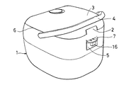
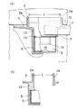
以下、添付図面に基づいてこの発明の実施の形態を説明する。図1は炊飯器の斜め後方から見た斜視図である。この図から分かるように、炊飯器は本体1、その後端部のヒンジ部2に開閉自在に取付けられた蓋3、本体1の左右両側面に揺動自在に取付けられた逆Uの字形のハンドル4及び本体1の後面に着脱自在に取付けた露受けケース5とから成る。ハンドル4は、本体1の上縁6に接近して取付けられ、後方に倒した状態でハンドル4の一方の側縁が本体1の上縁6とほぼ一致する(図3及び図4(b)参照)。また、本体1の後面においてヒンジ部2の下方に、後方に倒したハンドル4を水平に支持するための支持片7が一体成形により後方に突き出して設けられる。支持片7は、平面形状がほぼ半楕円形の板状に形成される(図4(a)参照)。前記の支持片7の下方において、本体1の後面に後方に開放された四角形の凹部からなる収納部8が設けられ、前記の露受けケース5がその後方から着脱自在に収納される。
【0016】
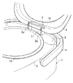
図3に示すように、本体1の上面においてヒンジ部2の近辺、即ち、炊飯釜10の後方に露集合溝9が形成される。露集合溝9はヒンジ部2に近づくに従って下降するように緩い勾配がつけられ、そのヒンジ部2において露集合溝9の底部に排水穴11が設けられる。
【0017】
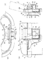
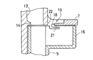
ヒンジ部2は、図4(a)に示すように、横断面形状が前方に開放されたコの字形に形成され、その左右両側部にヒンジ支持部2a、2aを有し、そのヒンジ支持部2a,2a間に挿通したヒンジ軸12により蓋3が開閉自在に取付けられる。前記の排水穴11はコの字形のヒンジ部2に囲まれた長方形をなし、その長方形の横断面形状をもった縦方向の通路13が本体1の内部に設けられ(図4(b)参照)、その下端が前記の収納部8の上面に開放されている。通路13と収納部8との境界部分の内側面に前後方向のガイドリブ14が設けられ、露受けケース5の上端面を規制する。また、収納部8の底面には前後方向の2本のガイドリブ15、15が設けられ、露受けケース5の差し込み時又は引き抜き時の摩擦抵抗を軽減している。なお、前記の排水穴11を複数の穴により形成してもよい。その場合の通路13はこれらの穴に共通して1つだけ設けられる。単独又は複数の穴のいずれの場合も、その開口の範囲内に露受けケース5の開口が含まれるようにこれらの大きさ関係が設定される。
【0018】
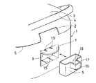
前記の露受けケース5の後端面に後方に突き出したケース補助部16が設けられる(図2参照)。このケース補助部16は、露受けケース5の後端縁の中央部から後方に突き出したコの字形の上端縁17を有し、その深さは露受けケース5の深さのほぼ半分であり、上方と内方に開放される。露受けケース5を収納部8に収納した状態で、その後端面は本体1の後端面と同一面となるように収納部8の奥行きと露受けケース5の前後方向の幅が設定されている。ケース補助部16は本体1の後端面から突き出すが、その突き出し量は、平面的に支持片7の大きさの範囲内に収まるように形成される。本体1の後端面から突き出したケース補助部16は把持部となり、その両側面を指先でつまむことにより露受けケース5を把持することができる。
【0019】
前記の支持片7の下面とケース補助部16の上縁は上下に接近して対向しており、ケース補助部16の上部両側縁に一対の凸部18が形成され、また、これに対向した一対の凹部19が支持片7側に形成される。凹部19は支持片7の一部を薄肉に形成してなるベンディング部21と、そのベンディング部21と本体1の後端面との間に形成された穴22とにより形成される(図4(c)参照)。露受けケース5を収納部8内に差し込むと、前記の凸部18がベンディング部21を押上げて進み、穴22に対しクリック感をもって係合され、これにより露受けケース5の抜け止めが図られる。前記の凸部18と凹部19とにより、凹凸係合部が形成される。
【0020】
ベンディング部21は、図6に示すように、ケース補助部16側に設けてよい。この場合は、凸部18はそのベンディング部21の先端部に形成され、支持片7側の凹部19は穴22のみにより形成される。
【0021】
ベンディング部21があると、凹凸係合部の設計に余裕ができる利点があるが、成形精度が高く管理される場合はベンディング部21を省略し、凸部18と穴22、或いは凸部18と単なる凹部とにより凹凸係合部を形成するようにしてもよい。
【0022】
前記の収納部8の開口幅は、図4(b)に示すように、ヒンジ支持部2a、2aの間隔Lに等しい幅をもって形成される。また、図5(a)に示すように、ヒンジ部2の間隔Lを収納部8の開口幅より相対的に大きく形成し、その開口幅が間隔Lの範囲内に含まれるように形成する場合もある。これに対し、図5(b)のように、ヒンジ部2の間隔Lより収納部8の開口幅が大きい場合は、その収納部8の上部と露集合溝9の底面との間に、金型成形の技術上肉厚部23(いわゆる、肉溜り)が生じるため、ヒケの発生原因となる不都合がある。従って、収納部8の開口幅はヒンジ部2の間隔Lと一致するか又はその間隔内に含まれるように形成することが望ましい。
【0023】
実施の形態の炊飯器は以上のようなものであり、炊飯完了後に蓋3を開放すると、その内面の結露は露集合溝9に流れ落ち、排水穴11から通路13を経て露受けケース5内に落下する。露受けケース5内に溜まった露を排除する場合は、指先でケース補助部16の両側面をつまんで多少の力を加えると、凸部18が穴22から抜け出し、係合が外れて該露受けケース5を抜き出すことができる。空になった露受けケース5を元の状態に戻す際は、これを収納部8に差し込むと、凸部18がベンディング部21をベンディングさせて穴22にクリック感をもって係合し、該露受けケース5の抜け止め状態に保持される。
【0024】
【発明の効果】
以上のように、この発明は、後方に倒したハンドルを支持する支持片の下面と、露受けケースとの対向面間に相互にクリック感をもって係脱する凹凸係合部を設けた構成により、部品の追加を伴うことなく露受けケースを炊飯器本体に抜け止め状態に収納保持させることができる。また、バネ等の別部品を用いることなく、前記凹凸係合部にベンディグ機能を付加することもできる。
【0025】
なお、収納部の開口をヒンジ支持部の内側に含ませる(ヒンジ支持部の間隔に一致する場合も含む。)ように設定すると、成形技術上も問題がなく、良好な仕上がりが得られる。
【図面の簡単な説明】
【図1】実施の形態の斜視図
【図2】同上の一部分解斜視図
【図3】同上の蓋開放状態の一部斜視図
【図4】(a)同上のヒンジ部分の横断平面図
(b)(a)図のb−b線の断面図
(c)(a)図のc−c線の断面図
【図5】(a)同上の変形例のヒンジ部分の断面図
(b)同上の他の変形例のヒンジ部分の断面図
【図6】同上の凹凸係合部の変形例の断面図
【符号の説明】
1 本体
2 ヒンジ部
2a ヒンジ支持部
3 蓋
4 ハンドル
5 露受けケース
6 上縁
7 支持片
8 収納部
9 露集合溝
10 炊飯釜
11 排水穴
12 ヒンジ軸
13 通路
14 ガイドリブ
15 ガイドリブ
16 ケース補助部
17 上縁
18 凸部
19 凹部
21 ベンディング部
22 穴
23 肉厚部[0001]
TECHNICAL FIELD OF THE INVENTION
The present invention relates to a dew receiving structure of a rice cooker (including a rice cooker).
[0002]
[Prior art]
When the lid is opened after the rice cooker has finished cooking rice, dew condensation adhering to the inner surface of the lid may flow down the inner surface of the lid and accumulate in the hinge at the rear of the main body of the rice cooker. It is well known that a rice cooker is provided with a dew receiving structure in order to prevent the dew from spilling outside. In recent years, in order to prevent such dew condensation from occurring, a lid heater is generally provided.However, in order to avoid an increase in product cost due to the provision of the lid heater, a small-capacity low-cost rice cooker is used. Adopts a structure in which only the above-mentioned dew receiving structure is provided without providing a lid heater.
[0003]
On the other hand, in order to make the rice cooker portable, an inverted U-shaped handle is attached to the left and right sides of the rice cooker body so as to be swingable, and is usually laid down on the rear side of the body. There is conventionally known an apparatus that is started up and carried (see Patent Document 4).
[0004]
Note that the portable rice cooker disclosed in
[Patent Document 1]
Japanese Patent Publication No. 5-30454 (Example, FIG. 1, FIG. 2)
[Patent Document 2]
Japanese Utility Model Publication No. 6-30222 (Example, FIG. 1)
[Patent Document 3]
Microfilm of Japanese Utility Model Application No. 59-127807 (Japanese Utility Model Application Laid-Open No. 61-41611) (Example, FIG. 3)
[Patent Document 4]
JP 2000-70127 A (paragraph 0017, FIG. 1)
[0006]
[Problems to be solved by the invention]
With respect to the structure in which the dew receiving case is engaged with the main body in the dew receiving structures in
[0007]
In the case of
[0008]
In the case of FIG. 3 of
[0009]
SUMMARY OF THE INVENTION It is an object of the present invention to provide a rice cooker provided with a handle, in which there is no increase in the number of components, and a dew receiving structure that can be easily locked.
[0010]
[Means for Solving the Problems]
In order to solve the above problems, the present invention relates to a rice cooker main body, a lid attached to a hinge portion of the main body so as to be openable and closable, a handle slidably attached to left and right side surfaces of the main body, and the main body. A dew receiving case detachably attached to a rear surface of the main body, a support piece for supporting the handle, which is tilted rearward, is protruded from a rear surface of the main body, and a dew collecting groove including the hinge portion is formed on an upper surface of the main body. At the same time, a drain hole is provided at the bottom of the dew gathering groove at the hinge portion, a storage portion is provided below the drain hole toward the rear of the main body, and an open storage portion is provided at a lower portion of the support piece. In the dew receiving structure of the rice cooker in which the dew receiving case is housed, a configuration is provided in which a concave and convex engaging portion is provided between the lower surface of the support piece and the opposing surface of the dew receiving case so as to be mutually engaged and disengaged with a click feeling. .
[0011]
According to the above configuration, when the lid is opened after the rice cooking, the dew attached to the inner surface of the lid flows down into the dew collecting groove of the main body, and falls into the dew receiving case from the drain hole. When removing the dew receiving case, if a slight force is applied to pull it out rearward, the concave / convex engaging portion is disengaged, and is pulled rearward from the storage portion of the main body. Conversely, when the dew receiving case is mounted, if it is inserted into the storage portion from the rear of the main body and a slight force is applied, the concave / convex engagement portion engages with a click feeling and is held in the storage portion.
[0012]
It is possible to adopt a configuration in which the concave and convex engaging portions are mutually engaged and disengaged by bending. There is a merit that the design can afford only the dimensions to bend.
[0013]
Further, the dew receiving case has a rear end surface that is flush with the rear surface of the main body, and a case auxiliary portion that projects rearward within the width of the support piece is provided on the rear end surface. A configuration may be adopted in which the portion serves as a grip portion of the dew receiving case, and the above-mentioned concave and convex engaging portion is provided on the case auxiliary portion and a support piece facing the case auxiliary portion.
[0014]
Further, it is possible to adopt a configuration in which the hinge portion provided on the main body includes a pair of left and right hinge support portions, and the opening width of the dew receiving case is formed inside the left and right hinge support portions. Further, a configuration may be adopted in which the size of the dew collecting groove is formed so as to include the opening of the dew receiving case within the range of the drain hole provided in the dew collecting groove.
[0015]
BEST MODE FOR CARRYING OUT THE INVENTION
Hereinafter, embodiments of the present invention will be described with reference to the accompanying drawings. FIG. 1 is a perspective view of the rice cooker as viewed obliquely from behind. As can be seen from this figure, the rice cooker comprises a
[0016]
As shown in FIG. 3, a
[0017]
As shown in FIG. 4 (a), the
[0018]
A case
[0019]
The lower surface of the
[0020]
The bending
[0021]
The presence of the bending
[0022]
As shown in FIG. 4B, the opening width of the
[0023]
The rice cooker according to the embodiment is as described above. When the
[0024]
【The invention's effect】
As described above, the present invention has a configuration in which a concave / convex engaging portion that engages and disengages with a click feeling is provided between a lower surface of a support piece that supports a handle that is tilted rearward and a facing surface with a dew receiving case. The dew receiving case can be stored and held in the rice cooker body in a retaining state without adding components. Further, a bendig function can be added to the concave / convex engaging portion without using a separate component such as a spring.
[0025]
In addition, if the opening of the storage portion is set to be included inside the hinge support portion (including the case where the interval is equal to the interval between the hinge support portions), there is no problem in molding technology, and a good finish can be obtained.
[Brief description of the drawings]
FIG. 1 is a perspective view of an embodiment; FIG. 2 is a partially exploded perspective view of the same; FIG. 3 is a partial perspective view of the same in an open state of the lid; FIG. b) Cross-sectional view taken along the line bb in FIG. 5 (a). (c) Cross-sectional view taken along the line cc in FIG. 5 (a). FIG. 6 is a cross-sectional view of a hinge part according to another modification of the embodiment.
DESCRIPTION OF
Claims (5)
Priority Applications (1)
| Application Number | Priority Date | Filing Date | Title |
|---|---|---|---|
| JP2003024276A JP3974044B2 (en) | 2003-01-31 | 2003-01-31 | Rice cooker dew receiving structure |
Applications Claiming Priority (1)
| Application Number | Priority Date | Filing Date | Title |
|---|---|---|---|
| JP2003024276A JP3974044B2 (en) | 2003-01-31 | 2003-01-31 | Rice cooker dew receiving structure |
Publications (2)
| Publication Number | Publication Date |
|---|---|
| JP2004230010A true JP2004230010A (en) | 2004-08-19 |
| JP3974044B2 JP3974044B2 (en) | 2007-09-12 |
Family
ID=32952848
Family Applications (1)
| Application Number | Title | Priority Date | Filing Date |
|---|---|---|---|
| JP2003024276A Expired - Lifetime JP3974044B2 (en) | 2003-01-31 | 2003-01-31 | Rice cooker dew receiving structure |
Country Status (1)
| Country | Link |
|---|---|
| JP (1) | JP3974044B2 (en) |
Cited By (4)
| Publication number | Priority date | Publication date | Assignee | Title |
|---|---|---|---|---|
| JP2008286483A (en) * | 2007-05-18 | 2008-11-27 | Zojirushi Corp | Liquid vessel |
| JP2011125606A (en) * | 2009-12-21 | 2011-06-30 | Mitsubishi Electric Corp | Electric rice cooker |
| KR101294112B1 (en) | 2010-12-30 | 2013-08-08 | 주식회사 리홈쿠첸 | Bucket Assembly For Electric Rice Cooker |
| WO2017039091A1 (en) * | 2015-09-04 | 2017-03-09 | 주식회사 대유위니아 | Electric rice cooker |
Families Citing this family (1)
| Publication number | Priority date | Publication date | Assignee | Title |
|---|---|---|---|---|
| CN205671933U (en) * | 2014-11-18 | 2016-11-09 | 史伯梅 | Water storage case and electric cooker |
-
2003
- 2003-01-31 JP JP2003024276A patent/JP3974044B2/en not_active Expired - Lifetime
Cited By (6)
| Publication number | Priority date | Publication date | Assignee | Title |
|---|---|---|---|---|
| JP2008286483A (en) * | 2007-05-18 | 2008-11-27 | Zojirushi Corp | Liquid vessel |
| JP2011125606A (en) * | 2009-12-21 | 2011-06-30 | Mitsubishi Electric Corp | Electric rice cooker |
| KR101294112B1 (en) | 2010-12-30 | 2013-08-08 | 주식회사 리홈쿠첸 | Bucket Assembly For Electric Rice Cooker |
| WO2017039091A1 (en) * | 2015-09-04 | 2017-03-09 | 주식회사 대유위니아 | Electric rice cooker |
| KR20170028624A (en) * | 2015-09-04 | 2017-03-14 | 주식회사 대유위니아 | Electric rice cooker |
| KR102231032B1 (en) | 2015-09-04 | 2021-03-23 | 주식회사 위니아딤채 | Electric rice cooker |
Also Published As
| Publication number | Publication date |
|---|---|
| JP3974044B2 (en) | 2007-09-12 |
Similar Documents
| Publication | Publication Date | Title |
|---|---|---|
| JPS6239765Y2 (en) | ||
| EP1234519A3 (en) | Latch for a storage unit | |
| AU730082B2 (en) | Adjusting device for a screen of a computer | |
| JP2004230010A (en) | Drip case structure of rice cooker | |
| USD506924S1 (en) | Packaging for a holder with hand shower | |
| JPS5836328Y2 (en) | compact container | |
| JPS5911685Y2 (en) | compact | |
| JP5512605B2 (en) | Support for opening and closing the toilet lid of a Western-style toilet | |
| JPS638349Y2 (en) | ||
| JPS635606Y2 (en) | ||
| JP3513622B2 (en) | Cosmetic container | |
| JP2003235725A (en) | Steam exhaust structure for rice cooker | |
| JPS6312808Y2 (en) | ||
| JPS638340Y2 (en) | ||
| JPS5836333Y2 (en) | Cosmetic brush foldable compact container | |
| TWM341010U (en) | Compressing type trash can | |
| JP2520315Y2 (en) | Floppy disk case | |
| JPH0236403Y2 (en) | ||
| JPH03119310U (en) | ||
| JP2574880Y2 (en) | Pot hook device | |
| JPH0711692Y2 (en) | Compact container | |
| JP2001324150A (en) | Oven toaster | |
| JPH034170Y2 (en) | ||
| JPH0647371Y2 (en) | Cosmetic container | |
| JP3019631U (en) | A teapot with a lid that can be opened and closed with one hand |
Legal Events
| Date | Code | Title | Description |
|---|---|---|---|
| A621 | Written request for application examination |
Free format text: JAPANESE INTERMEDIATE CODE: A621 Effective date: 20050404 |
|
| A977 | Report on retrieval |
Free format text: JAPANESE INTERMEDIATE CODE: A971007 Effective date: 20070223 |
|
| A131 | Notification of reasons for refusal |
Free format text: JAPANESE INTERMEDIATE CODE: A131 Effective date: 20070306 |
|
| A521 | Request for written amendment filed |
Free format text: JAPANESE INTERMEDIATE CODE: A523 Effective date: 20070427 |
|
| TRDD | Decision of grant or rejection written | ||
| A01 | Written decision to grant a patent or to grant a registration (utility model) |
Free format text: JAPANESE INTERMEDIATE CODE: A01 Effective date: 20070612 |
|
| A61 | First payment of annual fees (during grant procedure) |
Free format text: JAPANESE INTERMEDIATE CODE: A61 Effective date: 20070613 |
|
| R150 | Certificate of patent or registration of utility model |
Ref document number: 3974044 Country of ref document: JP Free format text: JAPANESE INTERMEDIATE CODE: R150 Free format text: JAPANESE INTERMEDIATE CODE: R150 |
|
| FPAY | Renewal fee payment (event date is renewal date of database) |
Free format text: PAYMENT UNTIL: 20100622 Year of fee payment: 3 |
|
| FPAY | Renewal fee payment (event date is renewal date of database) |
Free format text: PAYMENT UNTIL: 20100622 Year of fee payment: 3 |
|
| FPAY | Renewal fee payment (event date is renewal date of database) |
Free format text: PAYMENT UNTIL: 20130622 Year of fee payment: 6 |
|
| R250 | Receipt of annual fees |
Free format text: JAPANESE INTERMEDIATE CODE: R250 |
|
| FPAY | Renewal fee payment (event date is renewal date of database) |
Free format text: PAYMENT UNTIL: 20130622 Year of fee payment: 6 |
|
| FPAY | Renewal fee payment (event date is renewal date of database) |
Free format text: PAYMENT UNTIL: 20160622 Year of fee payment: 9 |
|
| R250 | Receipt of annual fees |
Free format text: JAPANESE INTERMEDIATE CODE: R250 |
|
| R250 | Receipt of annual fees |
Free format text: JAPANESE INTERMEDIATE CODE: R250 |
|
| R250 | Receipt of annual fees |
Free format text: JAPANESE INTERMEDIATE CODE: R250 |
|
| EXPY | Cancellation because of completion of term |