JP2004229123A - Image forming apparatus network system - Google Patents
Image forming apparatus network system Download PDFInfo
- Publication number
- JP2004229123A JP2004229123A JP2003016635A JP2003016635A JP2004229123A JP 2004229123 A JP2004229123 A JP 2004229123A JP 2003016635 A JP2003016635 A JP 2003016635A JP 2003016635 A JP2003016635 A JP 2003016635A JP 2004229123 A JP2004229123 A JP 2004229123A
- Authority
- JP
- Japan
- Prior art keywords
- image
- image forming
- forming apparatus
- unit
- memory
- Prior art date
- Legal status (The legal status is an assumption and is not a legal conclusion. Google has not performed a legal analysis and makes no representation as to the accuracy of the status listed.)
- Withdrawn
Links
Images


Abstract
Description
【0001】
【発明の属する技術分野】
本発明は、画像形成装置ネットワークに関し、特に連結動作手段を有し、複数の画像形成装置で印刷を分担できる画像形成装置ネットワークシステムに関する。
【0002】
【従来の技術】
複写機、ファクシミリ装置、プリンタなどの画像形成装置が多用されているが、これらには複数の画像形成装置をネットワークを介して接続されたものがある。このような画像形成装置ネットワークシステムには、複数の画像形成装置によって連結動作を行うことができるものがある。
【0003】
連結動作とは、例えば1枚の原稿を100枚複写する際、作業を与えられた画像形成装置が他の画像形成装置と情報のやり取りをして2台の画像形成装置で1台あたり50枚ずつ印刷を行うなど、作業を分担して作業時間を短縮するような機能である。
【0004】
また従来の画像形成装置として、コンタクトガラス上にセットされた原稿を読み取って画像情報をメモリに記憶する原稿の読み取り操作を行った後に、画像情報に基づいて転写紙上に画像を印刷する印刷動作を繰り返し行うことにより、予め設定された部数(設定部数)のコピーを得られるようにしたものがある。
【0005】
また従来の技術として以下のような先行技術がある。
従来の画像形成装置ネットワークシステムでは、複数台の画像形成装置のうちの任意の1台で読み取られた原稿の画像情報と他の画像形成装置に転送して印刷を分配する場合の操作性を向上させた(特許文献1参照)。
【0006】
【特許文献1】
特開2000−69259号公報
【0007】
【発明が解決しようとする課題】
しかしながら、従来の画像形成装置ネットワークシステムにおいて、複数台の画像形成装置のうちの任意の1台(マスタ機)で読み取り完了後、もしくはすでに読み取られて外部記憶手段に蓄積されている原稿の画像情報を他の画像形成装置(スレーブ機)に転送して印刷を分配する場合に、印刷を分配する個々の画像形成装置の残メモリ容量は異なる場合があるので、マスタ機の残メモリ量を監視するだけでは、原稿の読み取り動作中に残メモリ量が「0」になり、原稿戻し操作を行うといった作業が必要となり、非効率であった。
【0008】
本発明は、係る問題に鑑みてなされたものであり、複数台の画像形成装置のうちの任意の1台で読み取られた、もしくはすでに読み取られて外部記憶手段に蓄積されている原稿の画像情報を他の画像形成装置に転送して印刷を分配する場合の走査製を向上させる画像形成装置を提供することを目的とする。
【0009】
【課題を解決するための手段】
上記目的を達成するために、請求項1記載の画像形成装置ネットワークシステムは、原稿を読み取る読み取り手段と、読み取り手段によって読み取られた画像を印刷する印刷手段と、読み取った画像を蓄積する蓄積手段を有する複数台の画像形成装置がネットワークを介して接続され、複数台の画像形成装置のうちの任意の1台で読み取られた画像情報を他の画像形成装置に転送して印刷を分配する連結動作手段と、単独動作か連結動作かを選択する選択手段とを有する画像形成装置ネットワークシステムにおいて、少なくとも1台の画像形成装置が、原稿の読み取り画像情報を連結動作手段を用いて他の画像形成装置に転送して印刷を分配処理する分配処理手段と、原稿の読み取り完了後、原稿の画像サイズが得られた時に、他の画像形成装置に対して、ネットワークを介してメモリ残量を確認する確認手段と、原稿の画像サイズとメモリ残量を比較する比較手段とを有することを特徴とする。
【0010】
請求項2記載の発明は、請求項1記載の画像形成装置ネットワークシステムであって、比較手段は、メモリ残量と画像サイズを比較して、比較結果から転送を行うか否かを判断する転送判断手段を有することを特徴とする。
【0011】
請求項3記載の発明は、請求項1または2記載の画像形成装置ネットワークシステムであって、転送判断手段は、比較手段によってメモリ残量と画像サイズを比較し、メモリ残量が画像サイズ以下の場合に他の画像形成装置に転送を中断すると判断することを特徴とする。
【0012】
請求項4記載の発明は、請求項1または2記載の画像形成装置ネットワークシステムであって、比較手段は、メモリ残量と画像サイズを比較して、メモリ残量が画像サイズ以上である場合に、メモリ残量が画像サイズ以上である画像形成装置を示す情報を表示する表示手段を有することを特徴とする。
【0013】
【発明の実施の形態】
次に添付図面を参照して本発明の実施形態を説明する。
図1は、画像形成装置の構成を示す。
画像形成装置は、自動原稿送り装置(以下ADF)1と原稿台2、給送ローラ3、給送ベルト4、排送ローラ5、コンタクトガラス6、原稿セット検知7、第1トレイ8、第2トレイ9、第3トレイ10、第1給紙ユニット11、第2給紙ユニット12、第3給紙ユニット13、縦搬送ユニット14、感光体15、搬送ベルト16、定着ユニット17、排紙ユニット18、読み取りユニット50、露光ランプ51、第1ミラー52、レンズ53、CCDイメージセンサ54、第2ミラー55、第3ミラー56、書き込みユニット57、レーザ出力ユニット58、結像レンズ59、ミラー60、フィニッシャ100、分岐偏向版101、スタッカ搬送ローラ102、スタッカ排紙ローラ103、スタッカ・トレイ104、ステープラ搬送ローラ105、ステープラ106、ステープラ排紙ローラ107、ステープル・トレイ108、落下ストッバ109、落下トレイ110、両面給紙ユニット111、分岐爪112から構成されている。
【0014】
図2は、操作部30の構成を示した図である。
操作部30は、液晶タッチパネル31とテンキー32、クリア/ストップキー33、プリントキー34、予熱キー35、リセットキー36から構成されている。液晶タッチパネル31には、モード設定のためのキーや画像形成装置の状態を示すメッセージが表示される。
【0015】
次に動作について説明する。
ADF1にある、原稿台2に原稿の画像面を上にして置かれた原稿束は、操作部30上のスタートキー34が押下されると、一番上の原稿から給送ローラ3、給送ベルト4によってコンタクトガラス6上の所定の位置に給送される。読み取りユニット50によってコンタクトガラス6上の原稿の画像データを読み取り後、読み取りが終了した原稿は、給送ベルト4および排送ローラ5によって排出される。さらに、原稿セット検知7にて原稿台2に次の原稿が有ることを検知した場合、前原稿と同様にコンタクトガラス6上に給送される。給送ローラ3、給送ベルト4、排送ローラ5はモータによって駆動される。
【0016】
第1トレイ8、第2トレイ9、第3トレイ10に積載された転写紙は、各々第1給紙装置11、第2給紙装置12、第3給紙装置13によって給紙され、縦搬送ユニット14によって感光体15に当接する位置まで搬送される。読み取りユニット50にて読み込まれた画像データは、書き込みユニット57からのレーザーによって感光体15に書き込まれ、現像ユニット27を通過することによってトナー像が形成される。そして、転写紙は感光体15の回転と等速で搬送ベルト16によって搬送されながら、感光体15上のトナー像が転写される。その後、定着ユニット17にて画像を定着させ、排紙ユニット18によって後処理装置のフィニシャ100に排出される。
【0017】
後処理装置のフィニシャ100は、通常排紙ローラ102方向と、ステープル処理部方向へに導く事ができる。切り替え板101を上に切り替える事により、搬送ローラ103を経由して通常排紙トレイ104側に排紙する事ができる。また、切り替え板101を下方向に切り替える事で、搬送ローラ105、107を経由して、ステープル台108に搬送する事ができる。
ステープル台108に積載された転写紙は、一枚排紙されるごとに紙揃え用のジョガー109によって、紙端面が揃えられ、一部のコピー完了と共にステープラ106によって綴じられる。ステープラ106で綴じられた転写紙群は自重によって、ステープル完了排紙トレイ110に収納される。
【0018】
一方、通常の排紙トレイ104は前後に移動可能な排紙トレイである。前後に移動可能な排紙トレイ部104は、原稿毎、あるいは、画像メモリによってソーティングされたコピー部毎に、前後に移動し、簡易的に排出されてくるコピー紙を仕分けるものである。
【0019】
転写紙の両面に画像を作像する場合は、各給紙トレイ8〜10から給紙され作像された転写紙を排紙トレイ104側に導かないで、経路切り替えの為の分岐爪112を上側にセットする事で、一旦両面給紙ユニット111にストックする。
【0020】
その後、両面給紙ユニット111にストックされた転写紙は再び感光体15に作像されたトナー画像を転写するために、両面給紙ユニット111から再給紙され、経路切り替えの為の分岐爪112を下側にセットし、排紙トレイ104に導く。この様に転写紙の両面に画像を作成する場合に両面給紙ユニット111は使用される。
【0021】
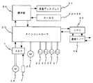
図4に示すように、感光体15、搬送ベルト16、定着ユニット17、排紙ユニット18、現像ユニット27はメインモータ25によって駆動され、各給紙装置11〜13はメインモータ25の駆動を各々給紙クラッチ22〜24によって伝達駆動される。縦搬送ユニット14はメインモータ25の駆動を中間クラッチ21によって伝達駆動される。
【0022】
図3は、操作部30の液晶タッチパネル31の表示一例を示した図である。
オペレータが液晶タッチパネル31に表示されたキーにタッチすることで、選択された機能を示すキーが黒く反転する。また、機能の詳細を指定しなければならない場合(例えば変倍であれば変倍値など)は、キーにタッチすることで、詳細機能の設定画面が表示される。このように液晶タッチパネルは、ドット表示器を使用しているため、その時の最適な表示をグラフィカルに行うことが可能である。
【0023】
図3において左上は、「コピーできます」、「お待ちください」などのメッセージを表示するメッセージエリア、その右は、セットした枚数を表示するコピー枚数表示部、転写紙を自動的に選択する自動用紙選択キー、コピーを一部ずつページ順にそろえる処理を指定するソートキー、コピーをページ毎に仕分けする処理を指定するスタックキー、ソート処理されたものを一部ずつ綴じる処理を指定するステープルキー、倍率を等倍にセットする等倍キー、拡大/縮小倍率をセットする変倍キー、両面モードを設定する両面キー、とじ代モードを設定する編集キー、表示/合紙モードを設定する表紙/合紙キー、デジタル複写機のネットワークを介して多量のプリント動作を複数に分けてプリントアウトする連結モードキーである。
また、給紙トレイ数に対応した給紙トレイ状態を示し、手動で給紙段を設定するためのキーが給紙段分表示されている。
【0024】
次に図1を参照して本発明の画像読み取り手段および画像を記録面上に潜像形成するまでの処理動作を説明する。
読み取りユニット50は、原稿を載置するコンタクトガラス6と光学走査系で構成されており、光学走査系には、露光ランプ51、第1ミラー52、レンズ53、CCDイメージセンサ54で構成されている。露光ランプ51および第1ミラー52は、図示しない第1キャリッジ上に固定され、第2ミラー55および第3ミラー56は図示しない第2キャリッジ上に固定されている。原稿像を読み取る時には、光路長が変わらないように、第1キャリッジ、第2キャリッジとが2対1の相対速度で機械的に走査される。
【0025】
光学走査系は、図示しないスキャナ駆動モータにて駆動される。原稿画像は、CCDイメージセンサ54によって読み取られ、電気信号に変換されて処理される。レンズ53およびCCDイメージセンサ54を左右方向に移動させることにより、画像倍率が変わる。すなわち指定された倍率に対応してレンズ53およびCCDイメージセンサ54に左右方向に位置が設定される。
【0026】
書込みユニット57は、レーザ出力ユニット58、結像レンズ59、ミラー60で構成され、レーザ出力ユニット58の内部には、レーザ光源であるレーザダイオードおよびモータによって高速で定速回転するポリゴンミラーが備わっている。
【0027】
レーザ出力ユニット58より照射されるレーザ光は、定速回転するポリゴンミラーで偏光され、結像レンズ59を通り、ミラー60で折り返され、感光体面上に集光結像する。偏光されたレーザ光は、感光体が回転する方向と直行する方向(主走査方向)に露光走査され、画像処理部のセレクタ64より出力された画像信号のライン単位の記録を行う。感光体の回転速度と記録密度に対応した所定の周期で主走査を繰り返すことによって、感光体面上に画像(静電潜像)が形成される。
【0028】
上記に示したように、書き込みユニット57から出力されるレーザ光が、画像作像系の感光体15に照射される。図示しない感光体15の一端近傍のレーザビームを照射される位置に、主走査同期信号を発生するビームセンサが配置されている。主走査同期信号をもとに主走査方向の画像記録開始タイミングの制御および画像信号の入出力を行うための制御信号の生成を行う。
【0029】
図5は、画像処理部の構成を示した図である。
露光ランプ51から照射された光は、原稿面を照射し、原稿面からの反射光をCCDイメージセンサ54にて結像レンズ(図示せず)により結像、受光して光電変換し、A/Dコンバータ61にてデジタル信号に変換する。デジタル信号に変換された画像信号は、シェーディング補正62がなされた後、画像処理部63にてMTF補正、γ補正などがなされる。セレクタ64では、画像信号の送り先を書き込みγ補正部71または画像メモリコントローラ65への切替えが行われる。
【0030】
書き込みγ補正部71を経由した画像信号は、書き込みユニット57に送られる。画像メモリコントローラ65とセレクタ64間は、双方向に画像信号を入出力可能な構成となっている。画像処理部(IPU)には、読み取り部50から入力される画像データ以外にも外部から供給される画像データ(例えばパーソナルコンピュータなどのデータ処理装置から出力されるデータ)も処理できるよう複数のデータの入出力の選択を行う機能を有している。
【0031】
画像メモリコントローラ65などへの設定や読み取り部50、書き込み部57の制御を行うCPU68およびそのプログラムやデータを格納するROM69、RAM70を備えている。さらにCPU68は、メモリコントローラ65を介して、画像メモリ66のデータの書き込み、読み出しが行える。また画像メモリ66の内容を退避させたり保存させたりするためのHDD71を備えている。
【0032】
図6は、セレクタ64における1ページ分の画像信号を示した図である。
フレームゲート信号(/FGATE)は、1ページの画像データの副走査方向の有効期間を表している。主走査同期信号(/LSYNC)は、1ライン毎の主走査同期信号であり、この信号が立ち上がった後の所定クロックで、画像信号が有効となる。ラインゲート信号(/LGATE)は、主走査方向の画像信号が有効であることを示す信号である。これらの信号は、画素クロックVCLKに同期しており、VCLKの1周期に対し1画素のデータが送られて来る。画像処理部(IPU)49は、画像入力、出力それぞれに対して別個の/FGTE、/LSYNC、/LGATE、VCLKの発生機構を有しており、様々な画像入手力の組み合わせが実現可能になる。
【0033】
また、作業分担するために他のデジタル複写機と画像データやコマンドの送受信を行う必要があるが、これは、画像データの送受信用にIEEE1394の連結インターフェースをコマンドの送受信用にシリアル通信ラインを用いている。図5に示すメモリコントローラが連結インターフェースドライバ80を介して実現している。
【0034】
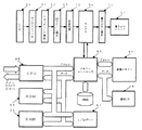
図7は、ソフトウェアのモジュール構成を示した図である。
アプリケーション層で設定されたジョブ情報は、スタートキーなどをトリガーにコントロールサービス層に受け渡される。コントロールサービス層は、アプリケーションからのジョブ情報を解釈し、ハンドラ層を動作させるためのプロセス情報をハンドラマネージャに要求する。ハンドラマネージャは、プロセス情報に従って個々のハンドラを動作させる。
【0035】
ハンドラには、読み取りユニットを制御するスキャナハンドラ206、219と画像メモリへの画像データの入出力を制御する画像メモリハンドラ207、218と書き込みユニットと用紙搬送、後処理周辺機を制御するプロッタハンドラ208、217を有し、ソフトウェアモジュールが連携して読み取りから画像メモリへの蓄積と画像形成の処理が行われる。
【0036】
さらに画像形成装置には、他の画像形成装置と連結するための連結I/Fドライバ204、214を備え、I/Fを介して画像データとコマンド情報の受け渡しが可能になる。連結コピージョブでは、親機側で発生した連結コピージョブは、親機のコントロールサービス203内でジョブ情報が解釈された後、スキャナで読み取った画像を画像メモリに蓄積するプロセスと画像を子機の画像メモリに転送するプロセスに分けて実行する。
【0037】
必要な画像の転送が完了すると子機のコントロールサービス215は、親機のコントロールサービス203から受け取った情報に従って、予め転送されている画像データを参照する印刷プロセスを生成し、子機のハンドラマネージャ216に印刷を要求する。子機のコントロールサービス215は、親機に対して自機で処理した印刷ジョブを親機に逐次通知する。この情報に従って親機のコントロールサービス203は、自機の印刷ジョブと子機側の印刷ジョブの経過を監視し、必要分の印刷を行う。
【0038】
親機側で発生した連結コピージョブは、親機のコントロールサービス203内でジョブ情報が解釈された後、スキャナで読み取った画像を画像メモリに蓄積するプロセスと画像を子機の画像メモリに転送するプロセスに分けて実行する。必要な画像の転送が完了すると、子機のコントロールサービス215は、親機のコントロールサービス203から受け取った情報に従って、予め転送されている画像データを参照する印刷プロセスを生成し、子機のハンドラマネージャ216に印刷を要求する。
【0039】
子機のコントロールサービス215は、親機に対して自機で処理した印刷ジョブを親機に逐次通知する情報に従って親機のコントロールサービス203は、自機の印刷ジョブと子機側の印刷ジョブの経過を監視し、必要分の印刷を行う。
【0040】
図8は、画像形成装置の動作環境を示した図である。
親機Aから読み取られた、もしくはすでに読み取り済みの原稿の画像サイズが500であったとき、子機B、子機C、子機Dのメモリ残量がそれぞれ、600、300、1000であった時、子機Cのメモリ残量が原稿サイズより小さいため、親機は子機Cに対して画像転送を行わない。子機B、子機Dは画像転送を受けて連結動作に入る。
【0041】
図9は、表示手段である表示画面の例を示した図である。
表示画面には、メモリ残量が原稿サイズより大きい子機の詳細が見られるようになっている。オペレータはこの情報を元にジョブを分担する子機を選択したり子機の使用状況がわかる。
【0042】
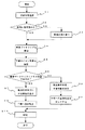
図10は、画像形成装置の処理動作を示したフローチャートである。
まず連結処理選択を行い(ステップS1)、原稿は蓄積済みか否かの判断を行う(ステップS2)。原稿が蓄積済みでない場合(ステップS2/NO)、原稿の読み取りを行う(ステップS3)。原稿が蓄積済みの場合は(ステップS2/YES)、次に原稿情報から画像サイズを獲得する(ステップS4)。次に親機は、子機となる画像形成装置のメモリ残量をネットワークを介して確認する(ステップS5)。
【0043】
ここでは、子機のメモリ残量と画像データサイズの比較を行う(ステップS6)。子機のメモリ残量が、画像データサイズより小さい場合には(ステップS6/NO)、親機表示手段に子機情報を非表示とし(ステップS8)、子機への画像転送をロックする(ステップS10)。子機のメモリ残量が画像データサイズより大きい場合は(ステップS6/YES)、親機表示手段に子機情報を表示し(ステップS7)、子機へ画像転送する(ステップS9)。次に画像転送の行われた子機、親機によって連結動作を行い印刷を行う(ステップS11)。
【0044】
【発明の効果】
以上の説明から明らかなように、転送前にメモリ残量を確認することで、メモリ残量が足らない場合には画像を転送しないのでメモリフルなどが発生することなく連結動作を効率良く行うことができる。
【0045】
また、子機のメモリ残量が原稿サイズ以上で連結動作が効率的に行うことができ、それを表示手段によってオペレータに通知することで、オペレータは子機となる画像形成装置を選択することができ、より利便性が向上する。
【図面の簡単な説明】
【図1】本発明の実施形態における画像形成装置の構成を示した図である。
【図2】本発明の実施形態における画像形成装置の操作部の構成を示した図である。
【図3】本発明の実施形態における液晶タッチパネルの表示一例を示した図である。
【図4】本発明の実施形態における画像形成装置ネットワークシステムの構成を示した図である。
【図5】本発明の実施形態における画像処理部の構成を示した図である。
【図6】本発明の実施形態におけるセレクタにおける1ページ分の画像信号を示した波形図である。
【図7】本発明の実施形態におけるソフトウェアのモジュールの構成を示した図である。
【図8】本発明の実施形態における画像形成装置ネットワークシステムの動作環境の模式図である。
【図9】本発明の実施形態における表示画面の表示画面例を示した図である。
【図10】本発明の実施形態における画像形成装置の処理動作を示した図である。
【符号の説明】
200、210 操作パネルマネージャ
201、211 他アプリ
202、213 コピーアプリ
203、215 コントロールサービス
204、214 連結I/Fドライバ
205、216 ハンドラ(リソース)マネージャ
206、219 スキャナハンドラ
207、218 画像メモリ(HDD)ハンドラ
208、217 プロッタハンドラ[0001]
TECHNICAL FIELD OF THE INVENTION
The present invention relates to an image forming apparatus network, and more particularly, to an image forming apparatus network system having a connection operation unit and capable of sharing printing by a plurality of image forming apparatuses.
[0002]
[Prior art]
2. Description of the Related Art Image forming apparatuses such as copiers, facsimile machines, and printers are frequently used, and some of them are connected to a plurality of image forming apparatuses via a network. Some of such image forming apparatus network systems can perform a connecting operation by a plurality of image forming apparatuses.
[0003]
The link operation means that, for example, when copying 100 originals, the given image forming apparatus exchanges information with another image forming apparatus, and the two image forming apparatuses use the image forming apparatus to copy 50 sheets per one sheet. It is a function that reduces work time by sharing work, such as printing each time.
[0004]
Further, as a conventional image forming apparatus, a printing operation of reading an original set on a contact glass, performing an operation of reading an original storing image information in a memory, and then printing an image on transfer paper based on the image information is performed. In some cases, a predetermined number of copies (set number of copies) can be obtained by repeating the process.
[0005]
Further, there is the following prior art as a conventional technique.
In a conventional image forming apparatus network system, the operability in distributing printing by transferring image information of a document read by any one of a plurality of image forming apparatuses to another image forming apparatus is improved. (See Patent Document 1).
[0006]
[Patent Document 1]
JP 2000-69259 A
[Problems to be solved by the invention]
However, in a conventional image forming apparatus network system, after reading is completed by an arbitrary one (master unit) of a plurality of image forming apparatuses, or image information of a document already read and stored in an external storage unit. Is transferred to another image forming apparatus (slave unit) to distribute the printing, the remaining memory capacity of each image forming apparatus to which the printing is distributed may be different. Therefore, the remaining memory amount of the master unit is monitored. In this case, the remaining memory amount becomes “0” during the original reading operation, and an operation of returning the original is required, which is inefficient.
[0008]
The present invention has been made in view of such a problem, and has been made in consideration of the image information of a document read by an arbitrary one of a plurality of image forming apparatuses or already read and stored in an external storage unit. An object of the present invention is to provide an image forming apparatus capable of improving the scanning quality when transferring prints to another image forming apparatus and distributing printing.
[0009]
[Means for Solving the Problems]
In order to achieve the above object, an image forming apparatus network system according to
[0010]
According to a second aspect of the present invention, in the image forming apparatus network system according to the first aspect, the comparing unit compares the remaining amount of the memory with the image size, and determines whether to perform the transfer based on the comparison result. It is characterized by having judgment means.
[0011]
According to a third aspect of the present invention, there is provided the image forming apparatus network system according to the first or second aspect, wherein the transfer determination unit compares the remaining amount of the memory with the image size by the comparing unit, and the remaining amount of the memory is equal to or smaller than the image size. In this case, it is determined that the transfer to another image forming apparatus is interrupted.
[0012]
According to a fourth aspect of the present invention, in the image forming apparatus network system according to the first or second aspect, the comparing means compares the remaining amount of the memory with the image size, and determines that the remaining amount of the memory is equal to or larger than the image size. A display unit for displaying information indicating an image forming apparatus having a remaining memory capacity equal to or larger than the image size.
[0013]
BEST MODE FOR CARRYING OUT THE INVENTION
Next, an embodiment of the present invention will be described with reference to the accompanying drawings.
FIG. 1 shows a configuration of the image forming apparatus.
The image forming apparatus includes an automatic document feeder (hereinafter ADF) 1 and a document table 2, a
[0014]
FIG. 2 is a diagram illustrating a configuration of the
The
[0015]
Next, the operation will be described.
When the
[0016]
The transfer sheets stacked on the
[0017]
The
The transfer paper stacked on the staple table 108 is aligned with the
[0018]
On the other hand, the normal paper discharge tray 104 is a paper discharge tray that can move back and forth. The paper discharge tray unit 104 that can be moved back and forth moves back and forth and sorts the discharged copy paper easily for each document or for each copy unit sorted by the image memory.
[0019]
When images are formed on both sides of the transfer sheet, the transfer sheet fed and imaged from each of the
[0020]
Thereafter, the transfer paper stocked in the duplex paper supply unit 111 is re-fed from the duplex paper supply unit 111 in order to transfer the toner image formed on the photoconductor 15 again, and a
[0021]
As shown in FIG. 4, the photoconductor 15, the
[0022]
FIG. 3 is a diagram illustrating an example of a display on the liquid crystal touch panel 31 of the
When the operator touches a key displayed on the liquid crystal touch panel 31, the key indicating the selected function is inverted to black. If the details of the function need to be specified (for example, a variable magnification value in the case of variable magnification), a key is touched to display a detailed function setting screen. As described above, since the liquid crystal touch panel uses the dot display device, the optimal display at that time can be performed graphically.
[0023]
In the upper left of FIG. 3, a message area for displaying a message such as "Ready to copy" or "Please wait" is displayed. On the right is a copy number display section for displaying the number of sheets set, and an automatic sheet for automatically selecting a transfer sheet. Selection key, sort key to specify the process to arrange copies one by one in the page order, stack key to specify the process to sort copies by page, staple key to specify the process to bind the sorted items one by one, 1x key for setting to 1x, scaling key for setting enlargement / reduction ratio, 2x key for setting duplex mode, edit key for setting binding margin mode, cover / insert key for setting display / interleaf mode A link mode key for dividing a large number of print operations into a plurality of printouts via a digital copier network and printing out the plurality of printouts.
Further, the state of the paper feed tray corresponding to the number of paper feed trays is shown, and a key for manually setting the paper feed tray is displayed for each paper feed tray.
[0024]
Next, the image reading means of the present invention and the processing operation until an image is formed on a recording surface will be described with reference to FIG.
The reading unit 50 includes a
[0025]
The optical scanning system is driven by a scanner drive motor (not shown). The document image is read by the CCD image sensor 54, converted into an electric signal, and processed. The image magnification is changed by moving the lens 53 and the CCD image sensor 54 in the left and right direction. That is, the positions in the left and right directions are set on the lens 53 and the CCD image sensor 54 corresponding to the designated magnification.
[0026]
The
[0027]
The laser light emitted from the
[0028]
As described above, the laser light output from the
[0029]
FIG. 5 is a diagram illustrating a configuration of the image processing unit.
The light emitted from the exposure lamp 51 irradiates the original surface, and the reflected light from the original surface is imaged and received by an imaging lens (not shown) by the CCD image sensor 54 to be photoelectrically converted. The digital signal is converted by the
[0030]
The image signal that has passed through the writing γ correction unit 71 is sent to the
[0031]
A
[0032]
FIG. 6 is a diagram illustrating an image signal for one page in the selector 64.
The frame gate signal (/ FGATE) indicates an effective period of one page of image data in the sub-scanning direction. The main scanning synchronizing signal (/ LSYNC) is a main scanning synchronizing signal for each line, and the image signal becomes valid at a predetermined clock after this signal rises. The line gate signal (/ LGATE) is a signal indicating that the image signal in the main scanning direction is valid. These signals are synchronized with the pixel clock VCLK, and data of one pixel is sent for one cycle of VCLK. The image processing unit (IPU) 49 has separate generation mechanisms of / FGTE, / LSYNC, / LGATE, and VCLK for each of the image input and output, so that various combinations of image availability can be realized. .
[0033]
In order to share work, it is necessary to transmit and receive image data and commands to and from another digital copying machine. This is accomplished by using an IEEE1394 connection interface for transmitting and receiving image data and using a serial communication line for transmitting and receiving commands. ing. The memory controller shown in FIG. 5 is realized via the connection interface driver 80.
[0034]
FIG. 7 is a diagram illustrating a software module configuration.
The job information set in the application layer is transferred to the control service layer with a start key or the like as a trigger. The control service layer interprets job information from the application and requests process information for operating the handler layer from the handler manager. The handler manager operates individual handlers according to the process information.
[0035]
The handlers include
[0036]
Further, the image forming apparatus is provided with connection I /
[0037]
When the transfer of the necessary images is completed, the control service 215 of the slave unit generates a print process referring to the image data transferred in advance according to the information received from the
[0038]
After the job information is interpreted in the
[0039]
The control service 215 of the child device performs control of the print job of the child device and the print job of the child device in accordance with information that sequentially notifies the parent device of a print job processed by the child device. Monitor the progress and print as much as necessary.
[0040]
FIG. 8 is a diagram illustrating an operation environment of the image forming apparatus.
When the image size of the document read from master unit A or already read is 500, the remaining memory amounts of slave units B, C, and D are 600, 300, and 1000, respectively. At this time, since the remaining memory capacity of the child device C is smaller than the document size, the parent device does not perform image transfer to the child device C. The slave unit B and the slave unit D receive the image transfer and start the connection operation.
[0041]
FIG. 9 is a diagram showing an example of a display screen as a display unit.
On the display screen, details of the slave unit whose remaining memory is larger than the document size can be seen. Based on this information, the operator can select a slave unit to which the job is to be shared and can know the usage status of the slave unit.
[0042]
FIG. 10 is a flowchart illustrating the processing operation of the image forming apparatus.
First, a connection process is selected (step S1), and it is determined whether or not the document has been stored (step S2). If the document has not been stored (step S2 / NO), the document is read (step S3). If the document has been stored (step S2 / YES), the image size is obtained from the document information (step S4). Next, the parent device checks the remaining memory of the image forming apparatus serving as the child device via the network (step S5).
[0043]
Here, the remaining memory capacity of the slave unit and the image data size are compared (step S6). When the remaining memory capacity of the slave unit is smaller than the image data size (step S6 / NO), the slave unit information is not displayed on the master unit display means (step S8), and the image transfer to the slave unit is locked (step S8). Step S10). If the remaining memory capacity of the slave unit is larger than the image data size (step S6 / YES), the slave unit information is displayed on the master unit display means (step S7), and the image is transferred to the slave unit (step S9). Next, a connection operation is performed by the child device and the parent device to which the image has been transferred, and printing is performed (step S11).
[0044]
【The invention's effect】
As is clear from the above description, by confirming the remaining memory capacity before the transfer, if the remaining memory capacity is insufficient, the image is not transferred, so that the connection operation can be efficiently performed without causing the memory full or the like. Can be.
[0045]
When the remaining memory capacity of the slave unit is equal to or larger than the document size, the linking operation can be efficiently performed, and by notifying the operator of this by the display means, the operator can select the image forming apparatus to be the slave unit. It can be more convenient.
[Brief description of the drawings]
FIG. 1 is a diagram illustrating a configuration of an image forming apparatus according to an embodiment of the present invention.
FIG. 2 is a diagram illustrating a configuration of an operation unit of the image forming apparatus according to the exemplary embodiment of the present invention.
FIG. 3 is a diagram showing an example of display on a liquid crystal touch panel according to the embodiment of the present invention.
FIG. 4 is a diagram illustrating a configuration of an image forming apparatus network system according to the embodiment of the present invention.
FIG. 5 is a diagram illustrating a configuration of an image processing unit according to the embodiment of the present invention.
FIG. 6 is a waveform diagram showing an image signal for one page in the selector according to the embodiment of the present invention.
FIG. 7 is a diagram showing a configuration of software modules according to the embodiment of the present invention.
FIG. 8 is a schematic diagram of an operation environment of the image forming apparatus network system according to the embodiment of the present invention.
FIG. 9 is a diagram showing a display screen example of a display screen in the embodiment of the present invention.
FIG. 10 is a diagram illustrating a processing operation of the image forming apparatus according to the embodiment of the present invention.
[Explanation of symbols]
200, 210
Claims (4)
少なくとも1台の前記画像形成装置が、原稿の読み取り画像情報を前記連結動作手段を用いて他の画像形成装置に転送して印刷を分配処理する分配処理手段と、
原稿の読み取り完了後、原稿の画像サイズが得られた時に、他の画像形成装置に対して、ネットワークを介してメモリ残量を確認する確認手段と、
前記原稿の画像サイズと前記メモリ残量を比較する比較手段とを有することを特徴とする画像形成装置ネットワークシステム。A plurality of image forming apparatuses having reading means for reading a document, printing means for printing an image read by the reading means, and storage means for storing the read images, connected via a network, Of the image forming apparatus of any one of the above (1) to (2), transferring image information read by an arbitrary one of the image forming apparatuses to another image forming apparatus and distributing the print, and selecting means for selecting a single operation or a connecting operation. In an image forming apparatus network system,
Distribution processing means for at least one of the image forming apparatuses transferring read image information of a document to another image forming apparatus by using the linking operation means and performing print distribution processing;
After reading of the document is completed, when the image size of the document is obtained, checking means for checking the remaining amount of memory via a network to another image forming apparatus;
An image forming apparatus network system, comprising: comparing means for comparing the image size of the document with the remaining amount of memory.
Priority Applications (2)
| Application Number | Priority Date | Filing Date | Title |
|---|---|---|---|
| JP2003016635A JP2004229123A (en) | 2003-01-24 | 2003-01-24 | Image forming apparatus network system |
| US10/763,011 US7595903B2 (en) | 2003-01-23 | 2004-01-22 | Collaboration system, method and software program for image forming apparatuses |
Applications Claiming Priority (1)
| Application Number | Priority Date | Filing Date | Title |
|---|---|---|---|
| JP2003016635A JP2004229123A (en) | 2003-01-24 | 2003-01-24 | Image forming apparatus network system |
Publications (1)
| Publication Number | Publication Date |
|---|---|
| JP2004229123A true JP2004229123A (en) | 2004-08-12 |
Family
ID=32904029
Family Applications (1)
| Application Number | Title | Priority Date | Filing Date |
|---|---|---|---|
| JP2003016635A Withdrawn JP2004229123A (en) | 2003-01-23 | 2003-01-24 | Image forming apparatus network system |
Country Status (1)
| Country | Link |
|---|---|
| JP (1) | JP2004229123A (en) |
-
2003
- 2003-01-24 JP JP2003016635A patent/JP2004229123A/en not_active Withdrawn
Similar Documents
| Publication | Publication Date | Title |
|---|---|---|
| JP3895488B2 (en) | Digital copier network system | |
| JP2006184940A (en) | Image forming apparatus, method for controlling upgrade of software, its program and computer-readable information recording medium with the same recorded | |
| JP4056402B2 (en) | Image forming apparatus network system, image forming apparatus, connection operation method, and program | |
| JP4171348B2 (en) | Image forming system | |
| JP4121019B2 (en) | Image forming apparatus network system | |
| JP4121020B2 (en) | Image forming system | |
| JP4039954B2 (en) | Image forming system | |
| JP4012827B2 (en) | Image forming system, image forming apparatus, and image forming method | |
| JP2000335057A (en) | Image forming system and method therefor | |
| JP4366090B2 (en) | Image forming system and image forming apparatus | |
| JP2004237469A (en) | Image forming apparatus | |
| JP2004229123A (en) | Image forming apparatus network system | |
| JP4004412B2 (en) | Image forming apparatus | |
| JP4074201B2 (en) | Image forming apparatus | |
| JP2006256154A (en) | Image forming device and image forming method | |
| JP2000276310A (en) | Image forming system | |
| JPH10322533A (en) | Copying machine and copying machine network system | |
| JP2003283715A (en) | Image forming apparatus and image forming system | |
| JP2004222003A (en) | Image forming system and image forming device | |
| JP2005333388A (en) | System and apparatus for forming image | |
| JP4113818B2 (en) | Image forming connection system | |
| JPH11231730A (en) | Image forming device | |
| JP2004220092A (en) | Image forming apparatus | |
| JP2004215029A (en) | Image forming apparatus and image forming system | |
| JP2004236210A (en) | Image forming system |
Legal Events
| Date | Code | Title | Description |
|---|---|---|---|
| A300 | Withdrawal of application because of no request for examination |
Free format text: JAPANESE INTERMEDIATE CODE: A300 Effective date: 20060404 |