JP2004226511A - Image pickup lens device - Google Patents
Image pickup lens device Download PDFInfo
- Publication number
- JP2004226511A JP2004226511A JP2003011794A JP2003011794A JP2004226511A JP 2004226511 A JP2004226511 A JP 2004226511A JP 2003011794 A JP2003011794 A JP 2003011794A JP 2003011794 A JP2003011794 A JP 2003011794A JP 2004226511 A JP2004226511 A JP 2004226511A
- Authority
- JP
- Japan
- Prior art keywords
- group
- lens
- power
- lens system
- positive
- Prior art date
- Legal status (The legal status is an assumption and is not a legal conclusion. Google has not performed a legal analysis and makes no representation as to the accuracy of the status listed.)
- Pending
Links
Images


Abstract
Description
【0001】
【発明の属する技術分野】
本発明は撮像レンズ装置に関するものであり、特に被写体の映像を光学系により光学的に取り込んで撮像素子により電気的な信号として出力する撮像レンズ装置{例えば、デジタルスチルカメラ;デジタルビデオカメラ;デジタルビデオユニット,パーソナルコンピュータ,モバイルコンピュータ,携帯電話,携帯情報端末(PDA:Personal Digital Assistant)等に内蔵又は外付けされるカメラの主たる構成要素}、なかでも小型で高変倍率のズームレンズ系を備えた撮像レンズ装置に関するものである。
【0002】
【従来の技術】
近年、パーソナルコンピュータ等の普及に伴い、手軽に画像情報をデジタル機器に取り込むことの可能なデジタルスチルカメラやデジタルビデオカメラ等(以下単に「デジタルカメラ」という。)が個人ユーザーレベルで普及しつつある。そして、デジタルカメラは今後も画像情報の入力機器として益々普及することが予想される。このようなデジタルカメラの画質は、一般にCCD(Charge Coupled Device)等の固体撮像素子の画素数で決定される。現在、一般向けのデジタルカメラは100万画素を超える高画素化がなされており、画質面で銀塩フィルム用カメラに近づきつつある。このため、撮影レンズ系には撮像素子の高画素化に対応した高い光学性能が求められている。また、一般向けのデジタルカメラにおいても画像の変倍、特に画像劣化の少ない光学変倍が望まれている。しかし、撮影レンズ系において高性能化と高変倍率化とを両立させることは難しく、しかも一般向けデジタルカメラ用のズームレンズ系にはコンパクト化も要求される。これらの要求に応えるため従来より様々な提案がなされており(例えば、特許文献1〜4参照。)、従来のレンズシャッターカメラ用ズームレンズ系をデジタルカメラ用として使用することも一つの方法である。
【0003】
【特許文献1】
特開平7−306362号公報
【特許文献2】
特開平8−248314号公報
【特許文献3】
特開平9−230242号公報
【特許文献4】
特開平10−268193号公報
【0004】
【発明が解決しようとする課題】
しかし、従来より知られているズームレンズ系では、上述した複数の要求に同時に応えることは困難である。例えば、銀塩フィルム用のレンズシャッターカメラでは、使用されるズームレンズ系の射出瞳位置が像面の近くにあるため、それをデジタルカメラに用いると、固体撮像素子の前面に設けられているマイクロレンズの集光性能を十分に満足させることができず、画像中央部と画像周辺部とで画像の明るさが極端に変化してしまう。そして、従来より提案されているデジタルカメラ用のズームレンズ系では、その射出瞳位置を像面から離そうとすると、どうしてもズームレンズ系全体の大型化が避けられない。また、変倍比5倍以上の一般的な高変倍率ズームの場合、第1群に正のパワーを有するズームタイプ(いわゆるプラスリード)が採用されることが多いが、プラスリードを採用すると、全長をコンパクトにすることはできるものの、前玉径の大型化を招いてしまう。第1群に負のパワーを有するズームタイプ(いわゆるマイナスリード)を採用すると(特許文献1〜4等)、前玉径を小さくすることはできるものの、広角端での全長の大型化を招いてしまう。
【0005】
本発明はこのような状況に鑑みてなされたものであって、その目的は、高変倍率で高画質を満足するコンパクトなズームレンズ系を備えた撮像レンズ装置を提供することにある。
【0006】
【課題を解決するための手段】
上記目的を達成するために、第1の発明の撮像レンズ装置は、複数の群から成り群間隔を変えることにより変倍を行うズームレンズ系と、そのズームレンズ系により形成された光学像を電気的な信号に変換する撮像素子と、を備えた撮像レンズ装置であって、前記ズームレンズ系が、物体側から順に、負のパワーを有する第1群と、正のパワーを有する第2群と、正のパワーを有する第3群と、負のパワーを有する第4群と、正のパワーを有する第5群と、を少なくとも有し、広角端から望遠端までのズーミングに際し、少なくとも前記第1群が可動で、各群の間隔が変化し、前記第1群が最も物体側に負レンズを少なくとも有し、以下の条件式(1)を満足することを特徴とする。
−0.5<φ2/φ1<−0.01 …(1)
ただし、
φ1:第1群のパワー、
φ2:第2群のパワー、
である。
【0007】
第2の発明の撮像レンズ装置は、上記第1の発明の構成において、以下の条件式(2)を満足することを特徴とする。
−10<f12/fW<−1 …(2)
ただし、
f12:広角端での第1群と第2群との合成焦点距離、
fW:広角端でのズームレンズ系全体の焦点距離、
である。
【0008】
第3の発明の撮像レンズ装置は、複数の群から成り群間隔を変えることにより変倍を行うズームレンズ系と、そのズームレンズ系により形成された光学像を電気的な信号に変換する撮像素子と、を備えた撮像レンズ装置であって、前記ズームレンズ系が、物体側から順に、負のパワーを有する第1群と、正のパワーを有する第2群と、正のパワーを有する第3群と、負のパワーを有する第4群と、正のパワーを有する第5群と、正のパワーを有する第6群とを有し、広角端から望遠端までのズーミングに際し、少なくとも前記第1群が可動で、各群の間隔が変化することを特徴とする。
【0009】
【発明の実施の形態】
以下、本発明を実施した撮像レンズ装置を、図面を参照しつつ説明する。被写体の映像を光学的に取り込んで電気的な信号として出力する撮像レンズ装置は、被写体の静止画撮影や動画撮影に用いられるカメラ{例えば、デジタルカメラ;ビデオカメラ;デジタルビデオユニット,パーソナルコンピュータ,モバイルコンピュータ,携帯電話,携帯情報端末(PDA),これらの周辺機器(マウス,スキャナー,プリンター,その他のデジタル入出力機器)等に内蔵又は外付けされるカメラ}の主たる構成要素である。その撮像レンズ装置は、例えば図9に示すように、物体(被写体)側から順に、物体の光学像を形成する撮影レンズ系(TL)と、光学的ローパスフィルター等に相当する平行平面板(PL)と、撮影レンズ系(TL)により形成された光学像を電気的な信号に変換する撮像素子(SR)と、で構成される。
【0010】
後述する各実施の形態では、複数の群から成るズームレンズ系が撮影レンズ系(TL)として用いられ、複数の群が光軸(AX)に沿って移動し、各群の間隔を変化させることにより変倍(すなわちズーミング)が行われる。撮像素子(SR)としては、例えば複数の画素から成るCCD(Charge Coupled Device)やCMOS(Complementary Metal Oxide Semiconductor)センサー等の固体撮像素子が用いられ、ズームレンズ系により形成された光学像が撮像素子(SR)により電気的な信号に変換される。
【0011】
またズームレンズ系で形成されるべき光学像は、撮像素子(SR)の画素ピッチにより決定される所定の遮断周波数特性を有する光学的ローパスフィルター{平行平面板(PL)から成る。}を通過することにより、電気的な信号に変換される際に発生するいわゆる折り返しノイズが最小化されるように、空間周波数特性が調整される。光学的ローパスフィルターとしては、例えば所定の結晶軸方向が調整された水晶等を材料とする複屈折型ローパスフィルターや、必要とされる光学的な遮断周波数特性を回折効果により達成する位相型ローパスフィルター等が適用可能である。撮像素子(SR)で生成した信号は、必要に応じて所定のデジタル画像処理や画像圧縮処理等が施されてデジタル映像信号としてメモリー(半導体メモリー,光ディスク等)に記録されたり、場合によってはケーブルを介したり赤外線信号に変換されたりして他の機器に伝送される。
【0012】
なお、図9に示す撮像レンズ装置では、撮影レンズ系(TL)によって拡大側(共役長の長い側)の被写体から縮小側(共役長の短い側)の撮像素子(SR)への縮小投影が行われるが、撮像素子(SR)の代わりに2次元画像を表示する表示素子(例えば液晶表示素子)を用い、撮影レンズ系(TL)を投影レンズ系として使用すれば、縮小側の画像表示面から拡大側のスクリーン面への拡大投影を行う画像投影装置を構成することができる。つまり、以下に説明する各実施の形態のズームレンズ系は、撮影レンズ系(TL)としての使用に限らず、投影レンズ系としても好適に使用することが可能である。
【0013】
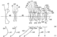
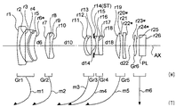
図1〜図4は、第1〜第4の実施の形態を構成するズームレンズ系にそれぞれ対応するレンズ構成図であり、広角端(W)でのレンズ配置を光学断面で示している。各レンズ構成図中、矢印mj(j=1,2,...)は広角端(W)から望遠端(T)へのズーミングにおける第j群(Grj)の移動をそれぞれ模式的に示している。ただし、可動群は第1群(Gr1)〜第5群(Gr5)であり、固定群である第6群(Gr6)は平行平面板(PL)と共にズーム位置固定になっている。また、各レンズ構成図中、ri(i=1,2,3,...)が付された面は物体側から数えてi番目の面(riに*印が付された面は非球面)であり、di(i=1,2,3,...)が付された軸上面間隔は、物体側から数えてi番目の軸上面間隔のうち、ズーミングにおいて変化する可変間隔である。
【0014】
各実施の形態のズームレンズ系はいずれも、物体側から順に、負のパワーを有する第1群(Gr1)と、正のパワーを有する第2群(Gr2)と、正のパワーを有する第3群(Gr3)と、負のパワーを有する第4群(Gr4)と、正のパワーを有する第5群(Gr5)と、正のパワーを有する第6群(Gr6)と、から成り(パワー:焦点距離の逆数で定義される量)、第3群(Gr3)又は第4群(Gr4)がその像側に絞り(ST)を含み、第1群(Gr1)〜第5群(Gr5)を可動群として各群間隔を変化させることによりズーミングを行う、変倍比5倍程度のズームレンズである。そして、CCD等の撮像素子(SR)を備えたカメラ(例えばデジタルカメラ)に用いられるズームレンズ系として、その像側には光学的ローパスフィルター,赤外カットフィルター等の光学フィルターや撮像素子(SR)のカバーガラス等に相当する1枚又は2枚のガラス製平行平面板(PL)が配置されている。各実施の形態のレンズ構成を更に詳しく以下に説明する。
【0015】
《第1の実施の形態(図1)》
第1の実施の形態のズームレンズ系は負・正・正・負・正・正の6群ズームレンズであり、各群は物体側から順に以下のように構成されている。第1群(Gr1)は、両凹の負レンズ(物体側面が非球面)1枚で構成されている。第2群(Gr2)は、像側に凸の負メニスカスレンズ(像側面が非球面)と、両凸の正レンズと、で構成されている。第3群(Gr3)は、物体側に凸の正メニスカスレンズ2枚で構成されている。第4群(Gr4)は、両凹の負レンズ(像側面が非球面)と、両凸の正レンズ(像側面が非球面)と、絞り(ST)と、で構成されている。第5群(Gr5)は、両凸の正レンズ1枚で構成されている。第6群(Gr6)は、像側に凸の正メニスカスレンズ(両面が非球面)1枚で構成されている。
【0016】
《第2の実施の形態(図2)》
第2の実施の形態のズームレンズ系は負・正・正・負・正・正の6群ズームレンズであり、各群は物体側から順に以下のように構成されている。第1群(Gr1)は、両凹の負レンズ(物体側面が非球面)1枚で構成されている。第2群(Gr2)は、両凹の負レンズ(像側面が非球面)と、物体側に凸の正メニスカスレンズと、で構成されている。第3群(Gr3)は、物体側に凸の正メニスカスレンズと、両凸の正レンズと、で構成されている。第4群(Gr4)は、両凹の負レンズ(像側面が非球面)と、両凸の正レンズと、絞り(ST)と、で構成されている。第5群(Gr5)は、物体側に凸の正メニスカスレンズと、像側に凸の正メニスカスレンズと、で構成されている。第6群(Gr6)は、像側に凸の正メニスカスレンズ(両面が非球面)1枚で構成されている。
【0017】
《第3の実施の形態(図3)》
第3の実施の形態のズームレンズ系は負・正・正・負・正・正の6群ズームレンズであり、各群は物体側から順に以下のように構成されている。第1群(Gr1)は、両凹の負レンズ(物体側面が非球面)1枚で構成されている。第2群(Gr2)は、像側に凸の負メニスカスレンズ(像側面が非球面)と、両凸の正レンズと、で構成されている。第3群(Gr3)は、物体側に凸の正メニスカスレンズ2枚で構成されている。第4群(Gr4)は、両凹の負レンズ(像側面が非球面)と、両凸の正レンズと、絞り(ST)と、で構成されている。第5群(Gr5)は、物体側に凸の正メニスカスレンズと、像側に凸の正メニスカスレンズと、で構成されている。第6群(Gr6)は、像側に凸の正メニスカスレンズ(両面が非球面)1枚で構成されている。
【0018】
《第4の実施の形態(図4)》
第4の実施の形態のズームレンズ系は負・正・正・負・正・正の6群ズームレンズであり、各群は物体側から順に以下のように構成されている。第1群(Gr1)は、物体側に凸の負メニスカスレンズ2枚と、物体側に凸の正メニスカスレンズ(像側面が非球面)と、で構成されている。第2群(Gr2)は、両凸の正レンズ及び両凹の負レンズから成る接合レンズで構成されている。第3群(Gr3)は、物体側に凸の負メニスカスレンズ及び両凸の正レンズから成る接合レンズと、絞り(ST)と、で構成されている。第4群(Gr4)は、両凹の負レンズ及び物体側に凸の正メニスカスレンズから成る接合レンズで構成されている。第5群(Gr5)は、両凸の正レンズ(像側面が非球面)と、物体側に凸の負メニスカスレンズ(像側面が非球面)と、で構成されている。第6群(Gr6)は、物体側に凸の正メニスカスレンズ(両面が非球面)1枚で構成されている。
【0019】
各実施の形態のズームレンズ系は、物体側から順に負・正・正・負・正・正のズーム群を備え、広角端(W)から望遠端(T)までのズーミングに際し、少なくとも第1群(Gr1)が可動で、各群の間隔が変化することに一つの特徴がある。第1群(Gr1)を可動にすることにより、前玉径を小さくしながら収差を補正することが可能になる。なかでも歪曲収差の効果的な補正(特に広角での歪曲収差の補正)が可能になる。したがって、ズームレンズ系の高性能化とともに高変倍率化及びコンパクト化を達成することができ、高画質の画像情報を得ることができる。しかも、射出瞳位置を像面から十分に離して、撮像素子(SR)の前面に設けられているマイクロレンズの集光性能を十分に満足させることができるため、ズームレンズ系全体の小型化とともに画像の明るさの均一化が可能となる。
【0020】
また、物体側から順に負・正・正・負・正のズーム群を少なくとも有し、少なくとも第1群(Gr1)を可動群とするズームレンズ系においては、各実施の形態のように第1群(Gr1)が最も物体側に負レンズを有することが望ましい。ズーム移動する第1群(Gr1)が最も物体側に負レンズを有する構成とすることにより、前玉径を小さくしながら収差補正をより効果的に行うことが可能になる。なかでも歪曲収差の補正(特に広角での歪曲収差の補正)を効果的に行うことが可能になる。したがって、ズームレンズ系の高性能化とともに高変倍率化及びコンパクト化を達成することができ、高画質の画像情報を得ることができる。第1群(Gr1)が最も物体側に有する負レンズとして、第1〜第3の実施の形態のように両凹の負レンズを用いることがコンパクト化を図る上で好ましく、第4の実施の形態のように物体側に凸の負メニスカスレンズを用いることが諸収差(特に広角での歪曲収差)を良好に補正する上で好ましい。さらに、第1〜第3の実施の形態のように、最も物体側に非球面を配置すれば、諸収差(特に広角での歪曲収差)を補正する上でより一層好ましいズームレンズ系を実現することができる。
【0021】
上記のように物体側から順に負・正・正・負・正のズーム群を少なくとも有するとともに、少なくとも第1群(Gr1)を可動群とするズームレンズ系においては、以下の条件式(1)を満足することが望ましい。
−0.5<φ2/φ1<−0.01 …(1)
ただし、
φ1:第1群(Gr1)のパワー、
φ2:第2群(Gr2)のパワー、
である。
【0022】
条件式(1)は、第1群(Gr1)のパワーに対する第2群(Gr2)のパワーの比に関して、満足することが望ましい条件範囲を規定している。条件式(1)を満たすようにパワー比を適切に設定することにより、良好な性能を有しかつコンパクトなズームレンズ系を実現することが可能となる。条件式(1)の上限を越えると、第2群(Gr2)の正のパワーが弱くなりすぎるため、レトロフォーカス度が大きくなり、それに続く第3群(Gr3)以降で、収斂作用を大きくしなければならなくなる。それにより収差劣化も大きくなるため好ましくない。逆に条件式(1)の下限を越えると、第2群(Gr2)の正のパワーが強くなりすぎるため、第2群(Gr2)で発生する収差(特に広角側での諸収差)が大きくなり、それを補正するためにレンズ枚数を増やす必要が生じてしまい、コンパクト化という点で好ましくない。
【0023】
以下の条件式(1a)を満足することが望ましく、条件式(1b)を満足することが更に望ましい。条件式(1a),(1b)は、上記条件式(1)が規定している条件範囲のなかでも、上記観点等からより一層好ましい条件範囲を規定している。
−0.2<φ2/φ1<−0.01 …(1a)
−0.1<φ2/φ1<−0.01 …(1b)
【0024】
また、第1群(Gr1)と第2群(Gr2)との合成焦点距離について、以下の条件式(2)を満足することが望ましい。
−10<f12/fW<−1 …(2)
ただし、
f12:広角端(W)での第1群(Gr1)と第2群(Gr2)との合成焦点距離、
fW:広角端(W)でのズームレンズ系全体の焦点距離、
である。
【0025】
条件式(2)は、第1群(Gr1)と第2群(Gr2)との合成焦点距離に関して、満足することが望ましい条件範囲を規定している。条件式(2)の上限を越えると、第1群(Gr1)と第2群(Gr2)との合成焦点距離の絶対値が小さくなりすぎるため、歪曲収差(特に広角側での負の歪曲収差)が著しくなり、良好な光学性能を確保することが困難になる。逆に条件式(2)の下限を越えると、第1群(Gr1)と第2群(Gr2)との合成焦点距離の絶対値が大きくなりすぎるため、第1群(Gr1)に入射する光線高さを低くすることができず、第1群(Gr1)のレンズ径の増大を招いてしまい、コンパクト化という点で好ましくない。
【0026】
以下の条件式(2a)を満足することが望ましく、条件式(2b)を満足することが更に望ましい。条件式(2a),(2b)は、上記条件式(2)が規定している条件範囲のなかでも、上記観点等からより一層好ましい条件範囲を規定している。
−5<f12/fW<−1 …(2a)
−3<f12/fW<−1 …(2b)
【0027】
なお、各実施の形態を構成しているズームレンズ系には、入射光線を屈折作用により偏向させる屈折型レンズ(つまり、異なる屈折率を有する媒質同士の界面で偏向が行われるタイプのレンズ)が用いられているが、使用可能なレンズはこれに限らない。例えば、回折作用により入射光線を偏向させる回折型レンズ,回折作用と屈折作用との組み合わせで入射光線を偏向させる屈折・回折ハイブリッド型レンズ,入射光線を媒質内の屈折率分布により偏向させる屈折率分布型レンズ等を用いてもよい。また、絞り(ST)のほかに不要光をカットするための光束規制板等を必要に応じて配置してもよく、プリズム類(例えば直角プリズム),ミラー類(例えば平面ミラー)等を光路中に配置することにより、その光学的なパワーを有しない面(例えば、反射面,屈折面,回折面)でズームレンズ系の前,後又は途中で光路を折り曲げてもよい{例えば、光軸(AX)を約90度折り曲げるようにして光束を反射させる。}。その折り曲げ位置は必要に応じて設定すればよく、光路の適正な折り曲げにより、ズームレンズ系が搭載されるデジタル入力機器(デジタルカメラ等)の見かけ上の薄型化やコンパクト化を達成することが可能である。
【0028】
【実施例】
以下、本発明を実施した撮像レンズ装置に用いられるズームレンズ系の構成等を、コンストラクションデータ等を挙げて更に具体的に説明する。ここで挙げる実施例1〜4は、前述した第1〜第4の実施の形態にそれぞれ対応しており、第1〜第4の実施の形態を表すレンズ構成図(図1〜図4)は、対応する実施例1〜4のレンズ構成をそれぞれ示している。
【0029】
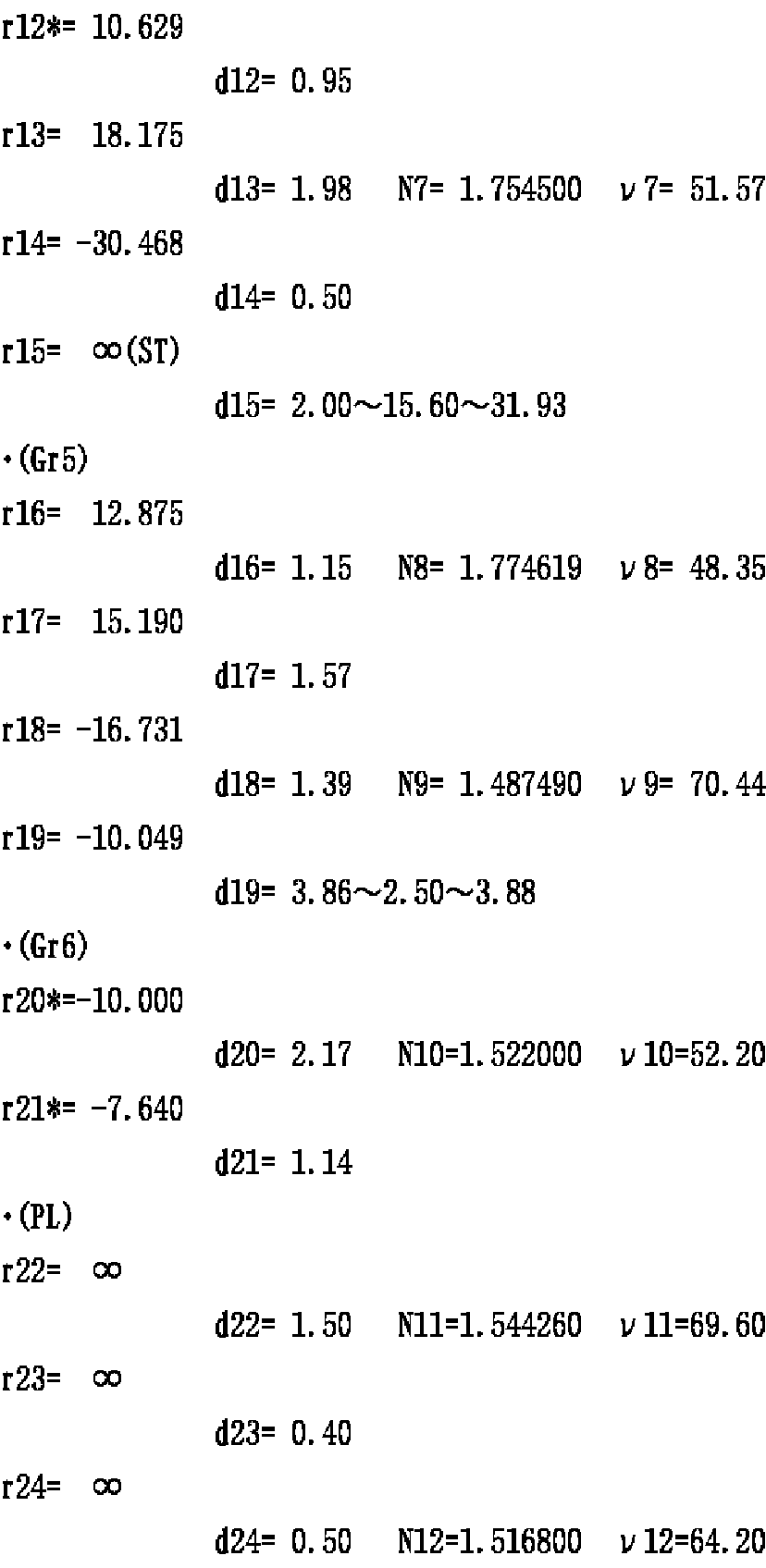
各実施例のコンストラクションデータにおいて、ri(i=1,2,3,...)は物体側から数えてi番目の面の曲率半径(mm)、di(i=1,2,3,...)は物体側から数えてi番目の軸上面間隔(mm)を示しており、Ni(i=1,2,3,...),νi(i=1,2,3,...)は物体側から数えてi番目の光学要素のd線に対する屈折率(Nd),アッベ数(νd)を示している。また、コンストラクションデータ中、ズーミングにおいて変化する軸上面間隔は、広角端(短焦点距離端,W)〜ミドル(中間焦点距離状態,M)〜望遠端(長焦点距離端,T)での可変空気間隔である。各焦点距離状態(W),(M),(T)に対応する全系の焦点距離(f,mm)及びFナンバー(FNO)を他のデータとあわせて示し、条件式対応値を表1に示す。
【0030】
曲率半径riに*印が付された面は、非球面(非球面形状の屈折光学面、非球面と等価な屈折作用を有する面等)であり、非球面の面形状を表わす以下の式(AS)で定義される。各実施例の非球面データを他のデータとあわせて示す(ただしAi=0の場合は省略する。)。
X(H)=(C0・H2)/{1+√(1−ε・C02・H2)}+Σ(Ai・Hi) …(AS)
ただし、式(AS)中、
X(H):高さHの位置での光軸(AX)方向の変位量(面頂点基準)、
H:光軸(AX)に対して垂直な方向の高さ、
C0:近軸曲率(=1/曲率半径)、
ε:2次曲面パラメータ、
Ai:i次の非球面係数、
である。
【0031】
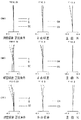
図5〜図8は実施例1〜実施例4にそれぞれ対応する収差図であり、(W)は広角端,(M)はミドル,(T)は望遠端における諸収差{左から順に、球面収差等,非点収差,歪曲収差である。Y’:最大像高(mm)}を示している。球面収差図において、実線(d)はd線、一点鎖線(g)はg線に対する各球面収差(mm)を表しており、破線(SC)は正弦条件不満足量(mm)を表している。非点収差図において、破線(DM)はメリディオナル面、実線(DS)はサジタル面でのd線に対する各非点収差(mm)を表わしている。また、歪曲収差図において実線はd線に対する歪曲(%)を表している。
【0032】
[第1面(r1)の非球面データ]
ε=1.0000,A4= 1.69516×10⁻⁴,A6=−9.22215×10⁻⁸,A8=−1.72092×10⁻⁸,A10= 2.28987×10⁻¹⁰,A12=−1.03129×10⁻¹²
[第4面(r4)の非球面データ]
ε=1.0000,A4= 6.47499×10⁻⁵,A6= 3.81050×10⁻⁷,A8=−1.13225×10⁻⁸,A10= 7.09299×10⁻¹¹
[第12面(r12)の非球面データ]
ε=1.0000,A4= 9.29282×10⁻⁵,A6=−1.06046×10⁻⁶,A8= 9.87989×10⁻⁹,A10=−1.95147×10⁻⁹,A12= 3.22844×10⁻¹¹
[第14面(r14)の非球面データ]
ε=1.0000,A4= 9.61046×10⁻⁶,A6= 4.84686×10⁻⁷,A8= 3.49901×10⁻⁸,A10= 8.49941×10⁻¹⁰
[第18面(r18)の非球面データ]
ε=1.0000,A4=−7.87505×10⁻⁴,A6=−2.13292×10⁻⁴,A8= 2.02083×10⁻⁵,A10=−1.60543×10⁻⁶,A12= 5.11886×10⁻⁸
[第19面(r19)の非球面データ]
ε=1.0000,A4= 7.31425×10⁻⁴,A6=−2.56008×10⁻⁴,A8= 1.87669×10⁻⁵,A10=−9.69295×10⁻⁷,A12= 2.32724×10⁻⁸
【0034】
![]()
[第1面(r1)の非球面データ]
ε=1.0000,A4= 1.95736×10⁻⁴,A6=−5.19646×10⁻⁷,A8=−1.24948×10⁻⁸,A10= 2.08863×10⁻¹⁰,A12=−1.00686×10⁻¹²
[第4面(r4)の非球面データ]
ε=1.0000,A4= 6.41215×10⁻⁵,A6= 1.52624×10⁻⁷,A8=−7.26193×10⁻⁹,A10=−3.44537×10⁻¹²
[第12面(r12)の非球面データ]
ε=1.0000,A4= 7.19196×10⁻⁵,A6=−5.59447×10⁻⁷,A8= 3.50651×10⁻⁸,A10=−1.08318×10⁻⁹,A12= 1.99744×10⁻¹¹
[第20面(r20)の非球面データ]
ε=1.0000,A4=−1.07352×10⁻³,A6=−2.47019×10⁻⁴,A8= 2.80856×10⁻⁵,A10=−2.16664×10⁻⁶,A12= 6.66306×10⁻⁸
[第21面(r21)の非球面データ]
ε=1.0000,A4= 1.01685×10⁻⁴,A6=−2.05149×10⁻⁴,A8= 1.70656×10⁻⁵,A10=−8.92408×10⁻⁷,A12= 2.06815×10⁻⁸
【0036】
![]()
[第1面(r1)の非球面データ]
ε=1.0000,A4= 2.10348×10⁻⁴,A6=−7.28474×10⁻⁷,A8=−1.23579×10⁻⁸,A10= 2.17205×10⁻¹⁰,A12=−1.03638×10⁻¹²
[第4面(r4)の非球面データ]
ε=1.0000,A4= 6.54762×10⁻⁵,A6= 4.93385×10⁻⁸,A8=−1.40494×10⁻⁸,A10= 1.14310×10⁻¹⁰
[第12面(r12)の非球面データ]
ε=1.0000,A4= 7.30805×10⁻⁵,A6=−4.81787×10⁻⁷,A8= 3.46128×10⁻⁸,A10=−1.12806×10⁻⁹,A12= 1.82616×10⁻¹¹
[第20面(r20)の非球面データ]
ε=1.0000,A4=−8.94572×10⁻⁴,A6=−2.51593×10⁻⁴,A8= 2.79102×10⁻⁵,A10=−2.18150×10⁻⁶,A12= 6.66306×10⁻⁸
[第21面(r21)の非球面データ]
ε=1.0000,A4= 1.66262×10⁻⁴,A6=−2.00695×10⁻⁴,A8= 1.69434×10⁻⁵,A10=−9.07297×10⁻⁷,A12= 2.06815×10⁻⁸
【0038】
[第6面(r6)の非球面データ]
ε=1.0000,A4=−1.32975×10⁻⁴,A6=−3.58439×10⁻⁷,A8= 1.62797×10⁻⁹,A10=−2.01336×10⁻⁹,A12= 5.90385×10⁻¹¹
[第20面(r20)の非球面データ]
ε=1.0000,A4= 2.63791×10⁻⁴,A6=−1.58642×10⁻⁶,A8= 2.65381×10⁻⁸,A10= 3.76773×10⁻¹⁰,A12=−5.16256×10⁻¹¹
[第22面(r22)の非球面データ]
ε=1.0000,A4= 1.83193×10⁻⁵,A6= 1.63866×10⁻⁶,A8= 4.46702×10⁻⁸,A10=−1.00935×10⁻⁹,A12= 2.76416×10⁻¹⁹
[第23面(r23)の非球面データ]
ε=1.0000,A4=−1.50180×10⁻³,A6=−5.62365×10⁻⁵,A8=−1.54610×10⁻⁶,A10= 4.71725×10⁻⁸
[第24面(r24)の非球面データ]
ε=1.0000,A4=−1.50348×10⁻³,A6=−5.79331×10⁻⁵,A8=−1.64961×10⁻⁶,A10= 1.03506×10⁻⁷
【0040】
【表1】
【発明の効果】
以上説明したように本発明によれば、物体側から順に負正正負正を有するズームレンズ系において少なくとも第1群がズーム移動可能に構成されており、第1群が最も物体側に負レンズを少なくとも有するとともに、前記条件式(1)を満たした構成になっているため、高変倍率で高画質を満足するコンパクトなズームレンズ系を備えた撮像レンズ装置を実現することができる。また、物体側から順に負正正負正正を有するズームレンズ系において少なくとも第1群がズーム移動可能に構成されているため、高変倍率で高画質を満足し、かつ、射出瞳位置を像面から十分に離したコンパクトなズームレンズ系を備えた撮像レンズ装置を実現することができる。そして本発明に係る撮像レンズ装置を、デジタルカメラ;ビデオカメラ;デジタルビデオユニット,パーソナルコンピュータ,モバイルコンピュータ,携帯電話,携帯情報端末(PDA),これらの周辺機器(マウス,スキャナー,プリンター,その他のデジタル入出力機器)等に内蔵又は外付けされるカメラ等に用いれば、これらの機器のコンパクト化,低コスト化,高変倍率化及び高性能化に寄与することができる。
【図面の簡単な説明】
【図1】第1の実施の形態(実施例1)のレンズ構成図。
【図2】第2の実施の形態(実施例2)のレンズ構成図。
【図3】第3の実施の形態(実施例3)のレンズ構成図。
【図4】第4の実施の形態(実施例4)のレンズ構成図。
【図5】実施例1の収差図。
【図6】実施例2の収差図。
【図7】実施例3の収差図。
【図8】実施例4の収差図。
【図9】本発明に係る撮像レンズ装置の概略光学構成を示す模式図。
【符号の説明】
TL …撮影レンズ系(ズームレンズ系)
Gr1 …第1群
Gr2 …第2群
Gr3 …第3群
ST …絞り
Gr4 …第4群
Gr5 …第5群
Gr6 …第6群
PL …平行平面板
SR …撮像素子
AX …光軸[0001]
TECHNICAL FIELD OF THE INVENTION
BACKGROUND OF THE
[0002]
[Prior art]
2. Description of the Related Art In recent years, with the spread of personal computers and the like, digital still cameras, digital video cameras, and the like (hereinafter, simply referred to as “digital cameras”) that can easily capture image information into digital devices have been spreading at the level of individual users. . Digital cameras are expected to become more and more popular as input devices for image information in the future. Generally, the image quality of such a digital camera is determined by the number of pixels of a solid-state imaging device such as a CCD (Charge Coupled Device). At present, general-purpose digital cameras have an increased number of pixels exceeding 1,000,000 pixels, and are approaching silver halide film cameras in terms of image quality. For this reason, the photographing lens system is required to have high optical performance corresponding to an increase in the number of pixels of the image sensor. In addition, there is a demand for zooming of an image in a digital camera for general use, in particular, optical zooming with less image deterioration. However, it is difficult to achieve both high performance and high magnification in a photographic lens system, and a compact zoom lens system for a digital camera for general use is also required. Various proposals have hitherto been made to meet these demands (for example, see
[0003]
[Patent Document 1]
JP-A-7-306362 [Patent Document 2]
JP-A-8-248314 [Patent Document 3]
Japanese Patent Application Laid-Open No. 9-230242 [Patent Document 4]
JP 10-268193 A
[Problems to be solved by the invention]
However, it is difficult for a conventionally known zoom lens system to simultaneously respond to the above-described plurality of requests. For example, in a lens shutter camera for a silver halide film, since the exit pupil position of a zoom lens system used is near an image plane, when it is used in a digital camera, a micro-lens provided on the front surface of a solid-state imaging device is used. The light-collecting performance of the lens cannot be sufficiently satisfied, and the brightness of the image changes extremely between the central portion and the peripheral portion of the image. In a conventionally proposed zoom lens system for a digital camera, if the position of the exit pupil is moved away from the image plane, the size of the entire zoom lens system cannot be avoided. Also, in the case of a general high-magnification zoom having a magnification ratio of 5 or more, a zoom type having a positive power (a so-called plus lead) is often used for the first lens unit. Although the overall length can be made compact, the diameter of the front lens increases. When a zoom type having a negative power (so-called minus lead) is employed for the first lens unit (
[0005]
The present invention has been made in view of such a situation, and an object of the present invention is to provide an imaging lens device including a compact zoom lens system that satisfies high image quality at a high magnification.
[0006]
[Means for Solving the Problems]
In order to achieve the above object, an imaging lens device according to a first aspect of the present invention includes a zoom lens system that includes a plurality of groups and performs zooming by changing a group interval, and an optical image formed by the zoom lens system. An imaging element for converting the zoom lens system into a first signal having a negative power and a second group having a positive power in order from the object side. , A third group having a positive power, a fourth group having a negative power, and a fifth group having a positive power, and when zooming from the wide-angle end to the telephoto end, at least the first group. The group is movable, the distance between the groups changes, the first group has at least a negative lens closest to the object side, and satisfies the following conditional expression (1).
−0.5 <φ2 / φ1 <−0.01 (1)
However,
φ1: power of the first group,
φ2: power of the second group,
It is.
[0007]
According to a second aspect of the present invention, in the imaging lens device according to the first aspect, the following conditional expression (2) is satisfied.
-10 <f12 / fW <-1 (2)
However,
f12: composite focal length of the first and second units at the wide-angle end,
fW: focal length of the entire zoom lens system at the wide-angle end,
It is.
[0008]
An imaging lens device according to a third aspect of the present invention includes a zoom lens system that includes a plurality of groups and performs zooming by changing a group interval, and an imaging device that converts an optical image formed by the zoom lens system into an electric signal. Wherein the zoom lens system includes, in order from the object side, a first unit having negative power, a second unit having positive power, and a third unit having positive power. A fourth group having a negative power, a fifth group having a positive power, and a sixth group having a positive power. At the time of zooming from the wide-angle end to the telephoto end, at least the first group It is characterized in that the groups are movable and the intervals between the groups change.
[0009]
BEST MODE FOR CARRYING OUT THE INVENTION
Hereinafter, an imaging lens device embodying the present invention will be described with reference to the drawings. 2. Description of the Related Art An imaging lens device that optically captures an image of a subject and outputs it as an electrical signal is a camera used for still image shooting or moving image shooting of a subject {for example, a digital camera; a video camera; a digital video unit, a personal computer, and a mobile. It is a main component of a camera built-in or externally attached to a computer, a mobile phone, a personal digital assistant (PDA), peripheral devices (mouse, scanner, printer, other digital input / output devices), and the like. For example, as shown in FIG. 9, the imaging lens device includes, in order from an object (subject) side, a photographing lens system (TL) for forming an optical image of the object, and a parallel plane plate (PL) corresponding to an optical low-pass filter or the like. ) And an image sensor (SR) that converts an optical image formed by the taking lens system (TL) into an electric signal.
[0010]
In each embodiment described below, a zoom lens system including a plurality of groups is used as a photographing lens system (TL), and the plurality of groups move along the optical axis (AX) to change the interval between the groups. (Ie, zooming) is performed. As the image sensor (SR), for example, a solid-state image sensor such as a CCD (Charge Coupled Device) comprising a plurality of pixels or a CMOS (Complementary Metal Oxide Semiconductor) sensor is used, and an optical image formed by a zoom lens system is used as the image sensor. (SR) is converted into an electrical signal.
[0011]
The optical image to be formed by the zoom lens system is composed of an optical low-pass filter / parallel plane plate (PL) having a predetermined cut-off frequency characteristic determined by the pixel pitch of the image sensor (SR). By passing through}, the spatial frequency characteristic is adjusted such that so-called aliasing noise generated when converted into an electric signal is minimized. Examples of the optical low-pass filter include, for example, a birefringent low-pass filter made of quartz or the like whose crystal axis direction is adjusted, and a phase-type low-pass filter that achieves a required optical cutoff frequency characteristic by a diffraction effect. Etc. are applicable. The signal generated by the image sensor (SR) is subjected to predetermined digital image processing and image compression processing as necessary, and is recorded as a digital video signal in a memory (semiconductor memory, optical disk, or the like). Or is converted to an infrared signal and transmitted to another device.
[0012]
In the imaging lens device illustrated in FIG. 9, the reduction projection from the object on the enlargement side (the side with the longer conjugate length) to the imaging element (SR) on the reduction side (the side with the shorter conjugate length) is performed by the imaging lens system (TL). However, if a display element (for example, a liquid crystal display element) for displaying a two-dimensional image is used instead of the imaging element (SR) and the taking lens system (TL) is used as a projection lens system, the image display surface on the reduction side can be obtained. , An image projection apparatus that performs enlarged projection from the image to the screen surface on the enlargement side can be configured. That is, the zoom lens system according to each of the embodiments described below can be suitably used not only as a photographing lens system (TL) but also as a projection lens system.
[0013]
FIGS. 1 to 4 are lens configuration diagrams respectively corresponding to the zoom lens systems constituting the first to fourth embodiments, and show the lens arrangement at the wide-angle end (W) in an optical cross section. In each lens configuration diagram, an arrow mj (j = 1, 2,...) Schematically shows movement of the j-th lens unit (Grj) during zooming from the wide-angle end (W) to the telephoto end (T). I have. However, the movable group is a first group (Gr1) to a fifth group (Gr5), and the sixth group (Gr6), which is a fixed group, has a fixed zoom position together with the plane-parallel plate (PL). In each lens configuration diagram, the surface marked with ri (i = 1, 2, 3,...) Is the i-th surface counted from the object side (the surface marked with * is an aspheric surface). ) And di (i = 1, 2, 3,...) Are the variable distances that change during zooming among the i-th axial distances counted from the object side.
[0014]
In any of the zoom lens systems according to the embodiments, in order from the object side, a first unit (Gr1) having a negative power, a second unit (Gr2) having a positive power, and a third unit (Gr2) having a positive power. A group (Gr3), a fourth group (Gr4) having negative power, a fifth group (Gr5) having positive power, and a sixth group (Gr6) having positive power (power: The third group (Gr3) or the fourth group (Gr4) includes a stop (ST) on the image side, and the first group (Gr1) to the fifth group (Gr5). This is a zoom lens with a zoom ratio of about 5 times, which performs zooming by changing the distance between the groups as a movable group. As a zoom lens system used for a camera (for example, a digital camera) having an image pickup device (SR) such as a CCD, an optical filter such as an optical low-pass filter and an infrared cut filter and an image pickup device (SR ), One or two parallel glass plates (PL) corresponding to the cover glass or the like are arranged. The lens configuration of each embodiment will be described in more detail below.
[0015]
<< First Embodiment (FIG. 1) >>
The zoom lens system of the first embodiment is a six-group negative / positive / positive / negative / positive / positive zoom lens. Each group is configured as follows in order from the object side. The first group (Gr1) includes one biconcave negative lens (object side surface is aspheric). The second group (Gr2) includes a negative meniscus lens (image side surface is aspheric) convex on the image side and a biconvex positive lens. The third group (Gr3) includes two positive meniscus lenses that are convex on the object side. The fourth group (Gr4) includes a biconcave negative lens (image side surface is aspheric), a biconvex positive lens (image side surface is aspheric), and a stop (ST). The fifth unit (Gr5) includes one biconvex positive lens. The sixth unit (Gr6) includes one positive meniscus lens (both surfaces are aspherical) convex on the image side.
[0016]
<< 2nd Embodiment (FIG. 2) >>
The zoom lens system according to the second embodiment is a six-group negative / positive / positive / negative / positive / positive zoom lens. Each group is configured as follows from the object side. The first group (Gr1) includes one biconcave negative lens (object side surface is aspheric). The second group (Gr2) includes a biconcave negative lens (image side surface is aspheric) and a positive meniscus lens convex on the object side. The third group (Gr3) includes a positive meniscus lens convex on the object side and a biconvex positive lens. The fourth group (Gr4) includes a biconcave negative lens (image side surface is aspheric), a biconvex positive lens, and a stop (ST). The fifth unit (Gr5) includes a positive meniscus lens convex on the object side and a positive meniscus lens convex on the image side. The sixth unit (Gr6) includes one positive meniscus lens (both surfaces are aspherical) convex on the image side.
[0017]
<< 3rd Embodiment (FIG. 3) >>
The zoom lens system according to the third embodiment is a six-group negative / positive / positive / negative / positive / positive zoom lens. Each group is configured as follows in order from the object side. The first group (Gr1) includes one biconcave negative lens (object side surface is aspheric). The second group (Gr2) includes a negative meniscus lens (image side surface is aspheric) convex on the image side and a biconvex positive lens. The third group (Gr3) includes two positive meniscus lenses that are convex on the object side. The fourth group (Gr4) includes a biconcave negative lens (image side surface is aspheric), a biconvex positive lens, and a stop (ST). The fifth unit (Gr5) includes a positive meniscus lens convex on the object side and a positive meniscus lens convex on the image side. The sixth unit (Gr6) includes one positive meniscus lens (both surfaces are aspherical) convex on the image side.
[0018]
<< 4th Embodiment (FIG. 4) >>
The zoom lens system according to the fourth embodiment is a six-group negative / positive / positive / negative / positive / positive zoom lens. Each group is configured as follows from the object side. The first group (Gr1) includes two negative meniscus lenses convex to the object side and a positive meniscus lens convex to the object side (the image side surface is aspheric). The second group (Gr2) includes a cemented lens including a biconvex positive lens and a biconcave negative lens. The third group (Gr3) includes a cemented lens including a negative meniscus lens convex to the object side and a biconvex positive lens, and a stop (ST). The fourth unit (Gr4) includes a cemented lens including a biconcave negative lens and a positive meniscus lens convex on the object side. The fifth unit (Gr5) includes a biconvex positive lens (image side surface is aspheric) and a negative meniscus lens convex to the object side (image side surface is aspheric). The sixth unit (Gr6) includes one positive meniscus lens (both surfaces are aspherical) convex on the object side.
[0019]
The zoom lens system according to each of the embodiments includes a negative / positive / positive / negative / positive / positive zoom group in order from the object side. At the time of zooming from the wide-angle end (W) to the telephoto end (T), at least the first One feature is that the group (Gr1) is movable and the interval between each group changes. By making the first lens unit (Gr1) movable, it becomes possible to correct the aberration while reducing the diameter of the front lens. Above all, effective correction of distortion (particularly correction of distortion at a wide angle) becomes possible. Therefore, it is possible to achieve high zoom ratio and high compactness as well as high performance of the zoom lens system, and obtain high-quality image information. In addition, since the exit pupil position is sufficiently separated from the image plane to sufficiently satisfy the light-collecting performance of the micro lens provided on the front surface of the image sensor (SR), the size of the zoom lens system can be reduced. The brightness of the image can be made uniform.
[0020]
Further, in a zoom lens system having at least a negative / positive / positive / negative / positive zoom group in order from the object side, and at least the first group (Gr1) as a movable group, the first lens unit as in each embodiment is used. It is desirable that the group (Gr1) has a negative lens closest to the object side. Since the first lens unit (Gr1) that moves the zoom has the negative lens closest to the object, aberration correction can be performed more effectively while reducing the diameter of the front lens. In particular, correction of distortion (particularly correction of wide-angle distortion) can be effectively performed. Therefore, it is possible to achieve high zoom ratio and high compactness as well as high performance of the zoom lens system, and obtain high-quality image information. It is preferable to use a biconcave negative lens as in the first to third embodiments as the negative lens which the first group (Gr1) has on the most object side in order to achieve compactness, and the fourth embodiment. It is preferable to use a negative meniscus lens convex to the object side as in the embodiment, in order to satisfactorily correct various aberrations (particularly, distortion at a wide angle). Further, by disposing an aspherical surface closest to the object as in the first to third embodiments, a zoom lens system that is more preferable for correcting various aberrations (particularly, distortion at a wide angle) is realized. be able to.
[0021]
As described above, in a zoom lens system having at least a negative / positive / positive / negative / positive zoom group in order from the object side and having at least a first group (Gr1) as a movable group, the following conditional expression (1) is satisfied. It is desirable to satisfy
−0.5 <φ2 / φ1 <−0.01 (1)
However,
φ1: power of the first group (Gr1),
φ2: power of the second group (Gr2),
It is.
[0022]
Conditional expression (1) defines a condition range that is desirably satisfied with respect to the ratio of the power of the second group (Gr2) to the power of the first group (Gr1). By appropriately setting the power ratio so as to satisfy the conditional expression (1), a compact zoom lens system having good performance can be realized. When the value exceeds the upper limit of the conditional expression (1), the positive power of the second lens unit (Gr2) becomes too weak, so that the retrofocus degree becomes large. In the subsequent third lens unit (Gr3) and thereafter, the convergence effect is increased. I have to. As a result, aberration deterioration is increased, which is not preferable. Conversely, if the lower limit of conditional expression (1) is exceeded, the positive power of the second lens unit (Gr2) becomes too strong, and aberrations (particularly, various aberrations on the wide-angle side) generated in the second lens unit (Gr2) are large. In order to correct this, the number of lenses needs to be increased, which is not preferable in terms of downsizing.
[0023]
It is desirable to satisfy the following conditional expressions (1a), and it is more desirable to satisfy the conditional expressions (1b). The conditional expressions (1a) and (1b) define a more preferable condition range from the above viewpoints among the condition ranges defined by the conditional expression (1).
−0.2 <φ2 / φ1 <−0.01 (1a)
−0.1 <φ2 / φ1 <−0.01 (1b)
[0024]
Further, it is preferable that the following conditional expression (2) is satisfied for the combined focal length of the first lens unit (Gr1) and the second lens unit (Gr2).
-10 <f12 / fW <-1 (2)
However,
f12: composite focal length of the first unit (Gr1) and the second unit (Gr2) at the wide-angle end (W),
fW: focal length of the entire zoom lens system at the wide-angle end (W),
It is.
[0025]
Conditional expression (2) defines a condition range that is desirably satisfied with respect to the combined focal length of the first lens unit (Gr1) and the second lens unit (Gr2). If the upper limit of conditional expression (2) is exceeded, the absolute value of the combined focal length of the first lens unit (Gr1) and the second lens unit (Gr2) becomes too small, so that distortion (particularly negative distortion on the wide-angle side) is obtained. ) Becomes remarkable, and it becomes difficult to secure good optical performance. Conversely, when the value goes below the lower limit of the conditional expression (2), the absolute value of the combined focal length of the first lens unit (Gr1) and the second lens unit (Gr2) becomes too large. The height cannot be reduced, which causes an increase in the lens diameter of the first group (Gr1), which is not preferable in terms of compactness.
[0026]
It is desirable to satisfy the following conditional expressions (2a), and it is more desirable to satisfy the conditional expressions (2b). The conditional expressions (2a) and (2b) define a more preferable condition range from the above viewpoints among the condition ranges defined by the conditional expression (2).
−5 <f12 / fW <−1 (2a)
-3 <f12 / fW <-1 (2b)
[0027]
The zoom lens system according to each of the embodiments includes a refractive lens that deflects an incident light ray by refraction (that is, a lens of a type that deflects at an interface between media having different refractive indexes). Although used, usable lenses are not limited to this. For example, a diffractive lens that deflects an incident light beam by a diffractive action, a hybrid refraction / diffractive lens that deflects an incident light ray by a combination of a diffractive action and a refracting action, and a refractive index distribution that deflects the incident light ray by a refractive index distribution in a medium A mold lens or the like may be used. In addition to the stop (ST), a light flux regulating plate or the like for cutting unnecessary light may be disposed as necessary. Prisms (for example, right-angle prisms), mirrors (for example, plane mirrors), etc. may be disposed in the optical path. , The optical path may be bent before, after, or in the middle of the zoom lens system on a surface having no optical power (for example, a reflecting surface, a refracting surface, or a diffractive surface). AX) is bent at about 90 degrees to reflect the light beam. }. The bending position can be set as required, and by appropriate bending of the optical path, it is possible to achieve the apparent thinness and compactness of digital input devices (such as digital cameras) equipped with a zoom lens system. It is.
[0028]
【Example】
Hereinafter, the configuration and the like of the zoom lens system used in the imaging lens device embodying the present invention will be described more specifically with reference to construction data and the like. Examples 1 to 4 described here correspond to the above-described first to fourth embodiments, respectively. The lens configuration diagrams (FIGS. 1 to 4) representing the first to fourth embodiments are as follows. , And corresponding lens configurations of Examples 1 to 4, respectively.
[0029]
In the construction data of each embodiment, ri (i = 1, 2, 3,...) Is the radius of curvature (mm) of the i-th surface counted from the object side, and di (i = 1, 2, 3,. ...) indicate the i-th axial top surface interval (mm) counted from the object side, and Ni (i = 1, 2, 3,...), Νi (i = 1, 2, 3,. .) Indicate the refractive index (Nd) and Abbe number (νd) of the i-th optical element counted from the object side with respect to the d-line. In the construction data, the distance between the top surfaces of the axes that changes during zooming is variable air at the wide-angle end (short focal length end, W) to the middle (intermediate focal length state, M) to the telephoto end (long focal length end, T). The interval. The focal length (f, mm) and F number (FNO) of the entire system corresponding to each focal length state (W), (M), (T) are shown together with other data, and the values corresponding to the conditional expressions are shown in Table 1. Shown in
[0030]
Surfaces marked with an asterisk (*) in the radius of curvature ri are aspherical surfaces (refracting optical surfaces having an aspherical shape, surfaces having a refracting action equivalent to an aspherical surface, and the like), and the following expression representing the aspherical surface shape ( AS). The aspherical surface data of each embodiment is shown together with other data (however, the case of Ai = 0 is omitted).
X (H) = (C0 · H 2) / {1 + √ (1-ε · C0 2 · H 2)} + Σ (Ai · H i) ... (AS)
However, in the expression (AS),
X (H): displacement amount in the optical axis (AX) direction at the position of height H (based on the surface vertex),
H: height in a direction perpendicular to the optical axis (AX),
C0: paraxial curvature (= 1 / radius of curvature),
ε: quadratic surface parameter,
Ai: i-th order aspherical coefficient,
It is.
[0031]
5 to 8 are aberration diagrams corresponding to Examples 1 to 4, respectively. (W) is the wide-angle end, (M) is the middle, (T) is the various aberrations at the telephoto end. Aberration, astigmatism, and distortion. Y ′: maximum image height (mm)}. In the spherical aberration diagram, the solid line (d) represents each spherical aberration (mm) with respect to the d-line, the one-dot chain line (g) with respect to the g-line, and the broken line (SC) represents the sine condition unsatisfactory amount (mm). In the astigmatism diagram, a dashed line (DM) represents a meridional surface, and a solid line (DS) represents each astigmatism (mm) with respect to a d-line on a sagittal surface. In the distortion diagrams, the solid line represents the distortion (%) with respect to the d-line.
[0032]
[Aspherical surface data of first surface (r1)]
ε = 1.0000, A4 = 1.69516 × 10 −4 , A6 = −9.2215 × 10 −8 , A8 = −1.72092 × 10 −8 , A10 = 2.28987 × 10 −10 , A12 = −1.03129 × 10 −12
[Aspherical surface data of fourth surface (r4)]
ε = 1.0000, A4 = 6.447499 × 10 −5 , A6 = 3.81050 × 10 −7 , A8 = −1.113225 × 10 −8 , A10 = 7.09299 × 10 −11
[Aspherical surface data of twelfth surface (r12)]
ε = 1.0000, A4 = 9.29292 × 10 −5 , A6 = −1.06046 × 10 −6 , A8 = 9.87989 × 10 −9 , A10 = −1.95147 × 10 −9 , A12 = 3.2284 × 10 -11
[Aspherical surface data of the fourteenth surface (r14)]
ε = 1.0000, A4 = 9.61046 × 10 −6 , A6 = 4.88466 × 10 −7 , A8 = 3.49901 × 10 −8 , A10 = 8.49941 × 10 −10
[Aspherical surface data of the eighteenth surface (r18)]
ε = 1.0000, A4 = −7.87055 × 10 −4 , A6 = −2.13292 × 10 −4 , A8 = 2.02083 × 10 −5 , A10 = −1.60543 × 10 −6 , A12 = 5.1886 × 10 −8
[Aspherical surface data of the nineteenth surface (r19)]
ε = 1.0000, A4 = 7.314 × 10 −4 , A6 = −2.56008 × 10 −4 , A8 = 1.87669 × 10 −5 , A10 = −9.6952 × 10 −7 , A12 = 2.332724 × 10 −8
[0034]
![]()
[Aspherical surface data of first surface (r1)]
ε = 1.0000, A4 = 1.95736 × 10 −4 , A6 = −5.1946 × 10 −7 , A8 = −1.2948 × 10 −8 , A10 = 2.08863 × 10 −10 , A12 = −1.00686 × 10 −12
[Aspherical surface data of fourth surface (r4)]
ε = 1.0000, A4 = 6.4121 × 10 −5 , A6 = 1.52624 × 10 −7 , A8 = −7.26193 × 10 −9 , A10 = −3.444537 × 10 −12
[Aspherical surface data of twelfth surface (r12)]
ε = 1.0000, A4 = 7.19196 × 10 −5 , A6 = −5.559447 × 10 −7 , A8 = 3.50651 × 10 −8 , A10 = −1.08318 × 10 −9 , A12 = 1.99744 × 10 −11
[Aspherical surface data of twentieth surface (r20)]
ε = 1.0000, A4 = −1.07352 × 10 −3 , A6 = −2.47019 × 10 −4 , A8 = 2.880856 × 10 −5 , A10 = −2.16664 × 10 −6 , A12 = 6.666306 × 10 −8
[Aspherical surface data of surface 21 (r21)]
ε = 1.0000, A4 = 1.16885 × 10 −4 , A6 = −2.05149 × 10 −4 , A8 = 1.70656 × 10 −5 , A10 = −8.92408 × 10 −7 , A12 = 2.06815 × 10 −8
[0036]
![]()
[Aspherical surface data of first surface (r1)]
ε = 1.0000, A4 = 2.10348 × 10 −4 , A6 = −7.28474 × 10 −7 , A8 = −1.2579 × 10 −8 , A10 = 2.17205 × 10 −10 , A12 = −1.03638 × 10 −12
[Aspherical surface data of fourth surface (r4)]
ε = 1.0000, A4 = 6.54762 × 10 −5 , A6 = 4.93385 × 10 −8 , A8 = −1.4494 × 10 −8 , A10 = 1.14310 × 10 −10
[Aspherical surface data of twelfth surface (r12)]
ε = 1.0000, A4 = 7.3805 × 10 −5 , A6 = −4.81787 × 10 −7 , A8 = 3.46128 × 10 −8 , A10 = −1.12806 × 10 −9 , A12 = 1.82616 × 10 −11
[Aspherical surface data of twentieth surface (r20)]
ε = 1.0000, A4 = −8.94572 × 10 −4 , A6 = −2.51593 × 10 −4 , A8 = 2.791102 × 10 −5 , A10 = −2.118150 × 10 −6 , A12 = 6.666306 × 10 −8
[Aspherical surface data of surface 21 (r21)]
ε = 1.0000, A4 = 1.66622 × 10 −4 , A6 = −2.0069 × 10 −4 , A8 = 1.694434 × 10 −5 , A10 = −9.07297 × 10 −7 , A12 = 2.06815 × 10 −8
[0038]
[Aspherical surface data of sixth surface (r6)]
ε = 1.0000, A4 = −1.3975 × 10 −4 , A6 = −3.5584 × 10 −7 , A8 = 1.627797 × 10 −9 , A10 = −2.01336 × 10 −9 , A12 = 5.90385 × 10 −11
[Aspherical surface data of twentieth surface (r20)]
ε = 1.0000, A4 = 2.63791 × 10 −4 , A6 = −1.58642 × 10 −6 , A8 = 2.65381 × 10 −8 , A10 = 3.77673 × 10 −10 , A12 = − 5.16256 × 10 -11
[Aspherical surface data of the 22nd surface (r22)]
ε = 1.0000, A4 = 1.83193 × 10 −5 , A6 = 1.63866 × 10 −6 , A8 = 4.46702 × 10 −8 , A10 = −1.00935 × 10 −9 , A12 = 2 .76416 × 10 −19
[Aspherical surface data of the 23rd surface (r23)]
ε = 1.0000, A4 = −1.5018 × 10 −3 , A6 = −5.62365 × 10 −5 , A8 = −1.54610 × 10 −6 , A10 = 4.771725 × 10 −8
[Aspherical surface data of the 24th surface (r24)]
ε = 1.0000, A4 = −1.50348 × 10 −3 , A6 = −5.77931 × 10 −5 , A8 = −1.64961 × 10 −6 , A10 = 1.03506 × 10 −7
[0040]
[Table 1]
【The invention's effect】
As described above, according to the present invention, in a zoom lens system having negative, positive, positive, negative, and positive in order from the object side, at least the first unit is configured to be zoom-movable, and the first unit includes a negative lens closest to the object side. Since it has at least a configuration that satisfies the conditional expression (1), it is possible to realize an imaging lens device including a compact zoom lens system that satisfies high image quality at a high magnification. Further, since at least the first unit is configured to be zoom-movable in a zoom lens system having negative, positive, positive, negative, positive, and positive in order from the object side, high image quality is satisfied at a high magnification, and the position of the exit pupil is set on the image plane. An imaging lens device having a compact zoom lens system sufficiently separated from the imaging lens device can be realized. The imaging lens device according to the present invention is used for a digital camera; a video camera; a digital video unit, a personal computer, a mobile computer, a mobile phone, a personal digital assistant (PDA), and their peripheral devices (mouse, scanner, printer, other digital If it is used for a camera or the like built in or attached to an input / output device, etc., it is possible to contribute to the downsizing, cost reduction, high magnification ratio, and high performance of these devices.
[Brief description of the drawings]
FIG. 1 is a lens configuration diagram of a first embodiment (Example 1).
FIG. 2 is a lens configuration diagram of a second embodiment (Example 2).
FIG. 3 is a lens configuration diagram of a third embodiment (Example 3).
FIG. 4 is a lens configuration diagram of a fourth embodiment (Example 4).
FIG. 5 is an aberration diagram of the first embodiment.
FIG. 6 is an aberration diagram of the second embodiment.
FIG. 7 is an aberration diagram of the third embodiment.
FIG. 8 is an aberration diagram of the fourth embodiment.
FIG. 9 is a schematic diagram showing a schematic optical configuration of an imaging lens device according to the present invention.
[Explanation of symbols]
TL: photographing lens system (zoom lens system)
Gr1 First group Gr2 Second group Gr3 Third group ST Stop Gr4 Fourth group Gr5 Fifth group Gr6 Sixth group PL Parallel plane plate SR Image sensor AX Optical axis
Claims (3)
前記ズームレンズ系が、物体側から順に、負のパワーを有する第1群と、正のパワーを有する第2群と、正のパワーを有する第3群と、負のパワーを有する第4群と、正のパワーを有する第5群と、を少なくとも有し、広角端から望遠端までのズーミングに際し、少なくとも前記第1群が可動で、各群の間隔が変化し、前記第1群が最も物体側に負レンズを少なくとも有し、以下の条件式(1)を満足することを特徴とする撮像レンズ装置;
−0.5<φ2/φ1<−0.01 …(1)
ただし、
φ1:第1群のパワー、
φ2:第2群のパワー、
である。An imaging lens device comprising a zoom lens system composed of a plurality of groups and performing zooming by changing a group interval, and an imaging element that converts an optical image formed by the zoom lens system into an electric signal. hand,
The zoom lens system includes, in order from the object side, a first unit having negative power, a second unit having positive power, a third unit having positive power, and a fourth unit having negative power. And at least a fifth lens group having a positive power, and at the time of zooming from the wide-angle end to the telephoto end, at least the first lens group is movable, the distance between the lens groups changes, and the first lens group is the most An imaging lens device having at least a negative lens on its side and satisfying the following conditional expression (1):
−0.5 <φ2 / φ1 <−0.01 (1)
However,
φ1: power of the first group,
φ2: power of the second group,
It is.
−10<f12/fW<−1 …(2)
ただし、
f12:広角端での第1群と第2群との合成焦点距離、
fW:広角端でのズームレンズ系全体の焦点距離、
である。2. The imaging lens device according to claim 1, wherein the following conditional expression (2) is satisfied;
-10 <f12 / fW <-1 (2)
However,
f12: composite focal length of the first and second units at the wide-angle end,
fW: focal length of the entire zoom lens system at the wide-angle end,
It is.
前記ズームレンズ系が、物体側から順に、負のパワーを有する第1群と、正のパワーを有する第2群と、正のパワーを有する第3群と、負のパワーを有する第4群と、正のパワーを有する第5群と、正のパワーを有する第6群とを有し、広角端から望遠端までのズーミングに際し、少なくとも前記第1群が可動で、各群の間隔が変化することを特徴とする撮像レンズ装置。An imaging lens device comprising a zoom lens system composed of a plurality of groups and performing zooming by changing a group interval, and an imaging element that converts an optical image formed by the zoom lens system into an electric signal. hand,
The zoom lens system includes, in order from the object side, a first unit having negative power, a second unit having positive power, a third unit having positive power, and a fourth unit having negative power. A fifth group having a positive power, and a sixth group having a positive power. At the time of zooming from the wide-angle end to the telephoto end, at least the first group is movable and the distance between the groups changes. An imaging lens device characterized by the above-mentioned.
Priority Applications (1)
| Application Number | Priority Date | Filing Date | Title |
|---|---|---|---|
| JP2003011794A JP2004226511A (en) | 2003-01-21 | 2003-01-21 | Image pickup lens device |
Applications Claiming Priority (1)
| Application Number | Priority Date | Filing Date | Title |
|---|---|---|---|
| JP2003011794A JP2004226511A (en) | 2003-01-21 | 2003-01-21 | Image pickup lens device |
Publications (1)
| Publication Number | Publication Date |
|---|---|
| JP2004226511A true JP2004226511A (en) | 2004-08-12 |
Family
ID=32900589
Family Applications (1)
| Application Number | Title | Priority Date | Filing Date |
|---|---|---|---|
| JP2003011794A Pending JP2004226511A (en) | 2003-01-21 | 2003-01-21 | Image pickup lens device |
Country Status (1)
| Country | Link |
|---|---|
| JP (1) | JP2004226511A (en) |
Cited By (3)
| Publication number | Priority date | Publication date | Assignee | Title |
|---|---|---|---|---|
| JP2007256427A (en) * | 2006-03-22 | 2007-10-04 | Fujinon Corp | Projection zoom lens and projection type display apparatus |
| US7876507B2 (en) | 2007-01-10 | 2011-01-25 | Canon Kabushiki Kaisha | Zoom lens |
| JP2015166851A (en) * | 2014-02-13 | 2015-09-24 | パナソニックIpマネジメント株式会社 | Projection optical system and projection device |
-
2003
- 2003-01-21 JP JP2003011794A patent/JP2004226511A/en active Pending
Cited By (4)
| Publication number | Priority date | Publication date | Assignee | Title |
|---|---|---|---|---|
| JP2007256427A (en) * | 2006-03-22 | 2007-10-04 | Fujinon Corp | Projection zoom lens and projection type display apparatus |
| US7876507B2 (en) | 2007-01-10 | 2011-01-25 | Canon Kabushiki Kaisha | Zoom lens |
| US7961404B2 (en) | 2007-01-10 | 2011-06-14 | Canon Kabushiki Kaisha | Zoom lens |
| JP2015166851A (en) * | 2014-02-13 | 2015-09-24 | パナソニックIpマネジメント株式会社 | Projection optical system and projection device |
Similar Documents
| Publication | Publication Date | Title |
|---|---|---|
| JP3598971B2 (en) | Imaging lens device | |
| JP3656089B2 (en) | Imaging lens device | |
| JP3391342B2 (en) | Imaging lens device | |
| JP4103475B2 (en) | Imaging lens device | |
| JP4259495B2 (en) | Variable magnification optical system | |
| JP4806976B2 (en) | Variable magnification optical system | |
| JP3864897B2 (en) | Imaging lens device | |
| JP2004245982A (en) | Imaging lens device and electronic equipment equipped with the same | |
| JP2002055278A (en) | Image pickup lens device | |
| JP2002082284A (en) | Imaging lens device | |
| JP2001343587A (en) | Image pickup lens device | |
| JP2009008845A (en) | Zoom lens and imaging apparatus | |
| JP2007072263A (en) | Variable power optical system | |
| JP3750672B2 (en) | Imaging lens device | |
| JP2007025123A (en) | Variable power optical system | |
| JP2012042927A (en) | Zoom lens system, imaging apparatus, and camera | |
| JP2004117826A (en) | Imaging apparatus | |
| JP2004102162A (en) | Superwide-angle lens | |
| JP3821087B2 (en) | Imaging lens device | |
| JP2005037576A (en) | Imaging lens device | |
| JP2004037967A (en) | Image pickup lens device | |
| JP4281307B2 (en) | Zoom lens system and imaging lens device | |
| JP2004117828A (en) | Image pickup device | |
| JP2003287681A (en) | Image pickup lens device | |
| JP2006323051A (en) | Variable power optical system |
Legal Events
| Date | Code | Title | Description |
|---|---|---|---|
| A711 | Notification of change in applicant |
Free format text: JAPANESE INTERMEDIATE CODE: A712 Effective date: 20050615 |