JP2004222865A - Mounting structure of glass unit - Google Patents
Mounting structure of glass unit Download PDFInfo
- Publication number
- JP2004222865A JP2004222865A JP2003012685A JP2003012685A JP2004222865A JP 2004222865 A JP2004222865 A JP 2004222865A JP 2003012685 A JP2003012685 A JP 2003012685A JP 2003012685 A JP2003012685 A JP 2003012685A JP 2004222865 A JP2004222865 A JP 2004222865A
- Authority
- JP
- Japan
- Prior art keywords
- glass
- spacer
- glass unit
- unit
- frame
- Prior art date
- Legal status (The legal status is an assumption and is not a legal conclusion. Google has not performed a legal analysis and makes no representation as to the accuracy of the status listed.)
- Granted
Links
Images


Abstract
Description
【0001】
【技術分野】
本発明は,ガラス枠にガラスユニットを着脱可能に取り付けてなるガラスユニットの取付構造に関する。
【0002】
【従来技術】
例えば,パチンコ遊技機は,遊技領域を有する遊技盤を取り付けた前枠と,この前枠に対して開閉自在に配設されたガラス扉とを有している。
そして,ガラス扉は,これに直接ガラスを設けるのではなく,これに対して着脱可能なガラスユニットにガラスを設け,このガラスユニットをガラス扉の枠部であるガラス枠に取り付けることにより構成されている。このような,パチンコ遊技機のガラス扉としては,例えば,特許文献1に示すものがある。
そして,ガラスユニットのガラス枠への取付は,ガラスユニットに設けたピン穴をガラス枠に設けたピンに挿入し,ピン及びピン穴の部分を止め金具等に係合して固定することにより行っている。
【0003】
【特許文献1】
特開平7−213691号公報(第15図等)
【0004】
【解決しようとする課題】
しかしながら,上記ピン及びピン穴は,複数箇所(通常4箇所が多い)に形成されており,各ピンを各ピン穴にそれぞれ同時に挿入することは必ずしも容易ではない。また,各ピンを各ピン穴に挿入して位置決めを行った後にこれらの各部分を止め金具等に係合して固定する際には,複数の箇所の係合を行う必要がある。
そのため,従来のガラス扉においては,ガラスユニットをガラス枠に対して取り付ける取付作業に時間がかかり,またガラスユニットをガラス枠から取り外す取外作業にも時間がかかる。
【0005】
本発明は,かかる従来の問題点に鑑みてなされたもので,ガラス枠に対するガラスユニットの取付,取外しが容易であるガラスユニットの取付構造を提供しようとするものである。
【0006】
【課題の解決手段】
本発明は,ガラス枠にガラスユニットを着脱可能に取り付けてなるガラスユニットの取付構造において,
上記ガラスユニットは,ガラス板と,該ガラス板の外縁を囲うよう配設された外縁部とを有しており,該外縁部の一側方部には,上記ガラス枠に対して上記ガラスユニットを回動可能に取り付けるための回動ヒンジ部を有しており,
上記ガラス枠は,上記ガラスユニットにより後方側から覆われる開口穴と,上記回動ヒンジ部と係合して,これを回動可能に支持する回動支持部とを有しており,
上記ガラスユニット及び上記ガラス枠には,それぞれ互いに上下方向に対面するユニット側対面部及び枠側対面部が形成されていると共に,上記ユニット側対面部の下面に対面するよう上記枠側対面部が形成されており,
上記ユニット側対面部又は上記枠側対面部の一方には,他方に向けて突出したスペーサ部が形成されており,他方には,上記スペーサ部と当接するスペーサ当接面と,上記スペーサ部を収納可能なスペーサ収納部とが形成されており,
上記ガラスユニットは,上記スペーサ部を上記スペーサ当接面に当接させて上記ガラス枠に対して浮上した状態で,上記回動ヒンジ部と上記回動支持部との係合により回動可能であり,上記スペーサ部が上記スペーサ収納部に対向した際には,該スペーサ収納部に上記スペーサ部を収納して上記ガラス枠に対して下降するよう構成してあることを特徴とするガラスユニットの取付構造にある(請求項1)。
【0007】
本発明の取付構造においては,上記ガラス板及び外縁部を設けて構成されるガラスユニットは,外縁部の一側方部に上記回動ヒンジ部を有しており,上記開口穴を設けて構成されるガラス枠は,上記回動支持部を有している。そして,回動ヒンジ部と回動支持部とにより,ガラスユニットとガラス枠との連結後には,ガラスユニットをガラス枠に対して回動自在にすることができる。
【0008】
また,上記ガラスユニットに設けたユニット側対面部と上記ガラス枠に設けた枠側対面部には,一方に上記スペーサ部が設けてあり,他方に上記スペーサ当接面及びスペーサ収納部が設けてある。
そして,本発明においては,上記スペーサ部が上記スペーサ当接面に当接することにより,ガラスユニットをガラス枠より浮上させた状態で回動可能にし,この回動を行った後で上記スペーサ部が上記スペーサ収納部に収納されて,ガラスユニットがガラス枠に対して下降する。
【0009】
すなわち,上記ガラスユニットを上記ガラス枠に取り付ける際には,ガラスユニットの回動ヒンジ部をガラス枠の回動支持部に係合させて,ガラスユニットとガラス枠とを連結する。そして,ガラスユニット又はガラス枠の一方に形成したスペーサ部を,他方に形成したスペーサ当接面に当接させて,ガラスユニットがガラス枠より浮上した状態を形成する。そして,この浮上状態においては,スペーサ部がスペーサ当接面の表面上を滑り,ガラスユニットはガラス枠に対して上記回動ヒンジ部及び回動支持部を回動中心にして回動することができる。
【0010】
そして,上記ガラスユニットを,上記ガラス枠に完全に又はほぼ重なる重なり位置まで回動させたときには,上記スペーサ部と上記スペーサ当接面との当接状態が外れて,ガラスユニットがガラス枠に対して下降すると共にスペーサ部が上記スペーサ収納部に収納される。すなわち,本発明の取付構造において上記ガラスユニットの取付を行う際には,上記回動ヒンジ部と回動支持部とを係合させ,その後は,ガラスユニットを上記重なり位置まで回動させるだけで,上記スペーサ部がスペーサ収納部に収納された,ガラスユニットの少なくとも概略の位置決めを行うことができる。
また,上記スペーサ部を上記スペーサ収納部に収納させた後には,ガラスユニットは,止め金具等で固定することなくガラス枠に取り付けることができる。
【0011】
また,一方で,上記ガラスユニットを上記ガラス枠より取り外す際には,ガラスユニットを持ち上げて,上記スペーサ部を上記スペーサ収納部から抜き出す。そして,上記回動ヒンジ部及び回動支持部を回動中心にしてガラスユニットを回動させる際には,上記スペーサ部が上記スペーサ当接面に当接し,ガラスユニットは上記浮上状態で回動される。そして,その後,回動ヒンジ部を回動支持部より取り外して,ガラスユニットをガラス枠から取り外すことができる。そのため,本発明の取付構造においては,上記ガラスユニットをガラス枠より取り外すことも容易である。
このように,本発明の取付構造においては,上記ガラスユニットは上記ガラス枠に対して取付,取外しが容易であり,短時間でガラスユニットの取付,取外しを行うことができる。
【0012】
【発明の実施の形態】
上述した本発明における好ましい実施の形態につき説明する。
本発明において,上記スペーサ部の上記スペーサ収納部への収納とは,スペーサ部とスペーサ収納部との間に隙間をほとんど形成しない状態で係合又は嵌合する場合だけでなく,多少の上記隙間を形成した状態で係合又は嵌合する場合等をも含む。
また,上記ガラス枠に対する上記ガラスユニットの位置決めとは,上記重なり位置にほぼ完全に静止される状態での位置決めだけでなく,上記重なり位置に対して多少のぐらつきを有した状態での位置決め等をも含む。
【0013】
本発明においては,上記スペーサ部及び上記スペーサ収納部は,それぞれ上記ユニット側対面部及び上記枠側対面部に複数形成されていることが好ましい(請求項2)。
この場合には,上記ガラスユニットは,複数のスペーサ部と上記スペーサ当接面とによって浮上が可能であり,複数のスペーサ部が複数のスペーサ収納部に収納されて,上記位置決めを行うことができる。そのため,ガラスユニットの浮上が容易であると共に,ガラスユニットの位置決めを安定して行うことができる。
【0014】
また,上記ガラスユニット及び上記ガラス枠は,上記スペーサ部が上記スペーサ収納部に収納された状態において,互いに係合するロック部を有していることが好ましい(請求項3)。
この場合には,上記ガラスユニット及びガラス枠に設けたロック部によって,上記ガラスユニットの位置決めを一層安定させることができる。
【0015】
また,上記ロック部は,上記ガラスユニットにおける上記外縁部の一側方部とは反対側の他側方部に設けられたユニット側ロック部と,該ユニット側ロック部に係合するように上記ガラス枠に設けられた枠側ロック部とからなることが好ましい(請求項4)。
この場合には,上記ガラスユニットの位置決めを行った際には,上記外縁部の一側方部における回動ヒンジ部と上記回動支持部との係合と,上記外縁部の他側方部におけるユニット側ロック部と上記枠側ロック部との係合を行うことができる。そのため,ガラスユニットは,左右両側において各部が係合し,このガラスユニットの位置決めを一層安定させることができる。
【0016】
また,上記回動支持部及び上記枠側ロック部は,上記ガラス枠における両側方部にそれぞれ設けた補強用板金にそれぞれ配設されていることが好ましい(請求項5)。
この場合には,上記ガラスユニットを上記ガラス枠に取り付けた際に,上記両側方部の補強用板金とガラスユニットとが強固に係合し,上記ガラスユニットの取付構造の強度を向上させることができる。
【0017】
また,上記ユニット側対面部は,上記ガラスユニットにおける上記外縁部の下方部に形成されており,上記枠側対面部は,上記下方部に形成されたユニット側対面部に対面するよう形成されていることが好ましい(請求項6)。
この場合には,上記ガラスユニット及び上記ガラス枠において,上記ユニット側対面部及び上記枠側対面部を設けることが容易である。
【0018】
また,上記スペーサ部と上記スペーサ収納部との少なくとも1つは,上記回動ヒンジ部と上記回動支持部とによる回動中心軸の近傍に設けてあることが好ましい(請求項7)。
この場合には,上記ガラス枠に対するガラスユニットの広い回動範囲内において,上記スペーサ部と上記スペーサ当接面との当接状態を形成することができる。
【0019】
また,上記ガラスユニット又は上記ガラス枠は,上記スペーサ部が上記スペーサ収納部に収納された状態において,上記ガラスユニットが上方にずれることを防止するための上下固定具を有していることが好ましい(請求項8)。
この場合には,上記上下固定具によって,上記ガラス枠に対して上記ガラスユニットを上下方向に固定することができる。そのため,ガラスユニットをガラス枠に取り付けた取付構造を安定して維持することができる。
【0020】
また,上記ガラスユニットは,該ガラスユニットを操作することができる取手部を有していることが好ましい(請求項9)。
この場合には,上記ガラスユニットは,上記取手部を持って操作することによって,上記ガラス枠に対して回動させることが容易である。また,ガラスユニットは,取手部を操作することによって,上記位置決めがなされた状態から浮上させることが容易になる。そのため,ガラスユニットの取付,取外し作業を一層容易に行うことができる。
【0021】
また,上記ガラス枠は,上記スペーサ部が上記スペーサ収納部に収納された状態において,上記ガラスユニットの荷重を受けるための荷重受け部を有していることが好ましい(請求項10)。
この場合には,上記荷重受け部によって,上記ガラスユニットの荷重を受けて,ガラス枠に対するガラスユニットの位置決め状態を安定させることができる。
【0022】
【実施例】
以下に,図面を用いて本発明のガラスユニットの取付構造にかかる実施例につき説明する。
(実施例1)
本例のガラスユニット3の取付構造1(以下にガラスユニット取付構造1という)は,図1〜図10に示すごとく,ガラス枠2にガラスユニット3を着脱可能に取り付けてなる。
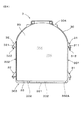
図6に示すごとく,上記ガラスユニット3は,ガラス板35と,このガラス板35の外縁を囲うよう配設された外縁部30とを有している。そして,外縁部30の一側方部301には,上記ガラス枠2に対して上記ガラスユニット3を回動可能に取り付けるための回動ヒンジ部31が形成されている。
【0023】
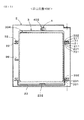
図7に示すごとく,上記ガラス枠2は,上記ガラスユニット3により後方側205から覆われる開口穴25と,上記回動ヒンジ部31と係合して,これを回動可能に支持する回動支持部21とを有している。
また,図1,図2に示すごとく,上記ガラスユニット3及び上記ガラス枠2には,それぞれ互いに上下方向に対面するユニット側対面部33及び枠側対面部23が形成されている。また,上記枠側対面部23は,上記ユニット側対面部33の下面に対面するよう形成されている。
【0024】
上記ユニット側対面部33又は上記枠側対面部23の一方には,他方に向けて突出したスペーサ部231が形成されている。また,他方には,上記スペーサ部231と当接するスペーサ当接面331と,上記スペーサ部231を収納可能なスペーサ収納部332とが形成されている。
【0025】
そして,図8,図10に示すごとく,上記ガラスユニット3は,上記スペーサ部231を上記スペーサ当接面331に当接させて上記ガラス枠2に対して浮上した状態(浮き上がらせた状態)で,上記回動ヒンジ部31と上記回動支持部21との係合により回動可能である。そして,図1,図5に示すごとく,上記ガラスユニット取付構造1は,上記スペーサ部231を上記スペーサ収納部332に収納することにより,上記ガラスユニット3が上記ガラス枠2に対して下降し,ガラス枠2に対するガラスユニット3の位置決めがなされるよう構成してある。
【0026】
以下に,これを詳説する。
以下に,上記ガラスユニット3を上記ガラス枠2に取り付けたものをガラス扉1という。すなわち,図1〜図5に示すごとく,本例のガラスユニット取付構造1は,ガラス扉1を構成する。
そして,本例においては,このガラス扉1をパチンコ遊技機10に用いる。本例のガラス扉1は,図2〜図4に示すごとく,パチンコ遊技機10の枠体5の前方側に,この枠体5に対してヒンジ部26(図1参照)により開閉可能に取り付けるものである。
【0027】
また,図2,図4に示すごとく,上記枠体5には,パチンコ遊技の遊技領域を有する遊技盤51が配設されており,上記ガラス扉1を上記枠体5に取り付けたときには,上記ガラスユニット3のガラス板35は,上記遊技盤51に対向する。
また,本例において,後方側205とは,パチンコ遊技機10において遊技者に対向しない側,すなわち外部に露出しない側で,上記枠体5に対向する側をいう。また,前方側とは,上記後方側205とは反対側をいい,パチンコ遊技機10において遊技者に対向する側をいう。
【0028】
また,図2,図4に示すごとく,本例のガラスユニット3は,複層ガラスユニット3であり,上記ガラス板35は,2枚のガラス351を対向配設した2重ガラス構造を有している。そして,上記外縁部30は,2枚のガラス351を対向させて固定するための一対の外周凹部306と,上記ガラス板35の外周側に位置する外周部305とを有している。
なお,上記ガラス板35は,1枚のガラス351により構成してもよく,3枚のガラス351により構成してもよい。
【0029】
図6に示すごとく,上記回動ヒンジ部31には,ユニット側第1対面部311が形成されており,図7に示すごとく,上記回動支持部21には,上記ユニット側第1対面部311の下面に対面する枠側第1対面部211が形成されている。
そして,本例では,図6に示すごとく,ユニット側第1対面部311の下面に,下方に向けて突出する第1突出ピン312を形成し,図7に示すごとく,枠側第1対面部211に第1突出ピン312を挿入配置するための第1ピン穴212を形成している。
なお,枠側第1対面部211の上面に,上方に向けて突出する第1突出ピン312を形成し,ユニット側第1対面部311に上記第1突出ピン312を挿入配置するための第1ピン穴212を形成しても勿論よい。
【0030】
また,図6に示すごとく,上記回動ヒンジ部31は,上記ガラスユニット3における外縁部30の一側方部301の複数箇所に形成されており,図7に示すごとく,上記回動支持部21は,上記複数の回動ヒンジ部31に係合するよう上記ガラス枠2の一側方部201における複数箇所に形成されている。本例では,回動ヒンジ部31及び回動支持部21は2箇所に形成されている。
【0031】
図1に示すごとく,本例のユニット側対面部33は,上記ガラスユニット3における外縁部30の下方部303に形成されており,上記枠側対面部23は,上記下方部303に形成されたユニット側対面部33に対面するよう形成されている。そして,本例では,枠側対面部23の上面に,ユニット側対面部33に向けて突出した上記スペーサ部231が形成されている。また,ユニット側対面部33の下面に,スペーサ部231と当接するスペーサ当接面331が形成されている。また,ユニット側対面部33には,スペーサ部231を収納可能なスペーサ収納部332が形成されている。
なお,ユニット側対面部33にスペーサ部231を形成し,枠側対面部23にスペーサ当接面331及びスペーサ収納部332を形成しても勿論よい。
【0032】
図1に示すごとく,上記スペーサ部231及びスペーサ収納部332は,それぞれガラスユニット3のユニット側対面部33における複数箇所(本例では5箇所)及びガラス枠2の枠側対面部23における複数箇所(本例では5箇所)に形成されている。本例では,ガラスユニット3における外縁部30の下方部303及びガラス枠2の下方部203(図7参照)において,複数のスペーサ部231及びスペーサ収納部332が,回動ヒンジ部31と回動支持部21とによる回動中心軸Xの近傍から間隔をあけて配置されている。そして,1つのスペーサ部231A及びスペーサ収納部332Aが,上記回動中心軸Xの近傍に位置している。
また,本例のスペーサ当接面331は,上記ガラスユニット3における外縁部30の下方部303(上記ユニット側対面部33)の下面である。
【0033】
図1に示すごとく,上記ガラスユニット3及び上記ガラス枠2は,ガラスユニット3の位置決めがなされた状態において,互いに係合するロック部22,32を有している。このロック部22,32は,ガラスユニット3における上記外縁部30の一側方部301とは反対側の他側方部302に設けられたユニット側ロック部32と,このユニット側ロック部32に係合するように上記ガラス枠2に設けられた枠側ロック部22とからなる。
【0034】
図6に示すごとく,上記ユニット側ロック部32には,ユニット側第2対面部321が形成されており,図7に示すごとく,上記枠側ロック部22には,上記ユニット側第2対面部321の下面に対面する枠側第2対面部221が形成されている。
そして,本例では,図6に示すごとく,ユニット側第2対面部321の下面に,下方に向けて突出する第2突出ピン322を形成し,図7に示すごとく,枠側第2対面部221に第2突出ピン322を挿入配置するための第2ピン穴222を形成している。
なお,枠側第2対面部221の上面に,上方に向けて突出する第2突出ピン322を形成し,ユニット側第2対面部321に上記第2突出ピン322を挿入配置するための第2ピン穴222を形成しても勿論よい。
【0035】
また,図6に示すごとく,上記ユニット側ロック部32は,ガラスユニット3における外縁部30の他側方部302における複数箇所に形成されており,図7に示すごとく,上記枠側ロック部22は,ガラス枠2の他側方部202における複数箇所に形成されている。本例では,ユニット側ロック部32及び枠側ロック部22は2箇所に形成されている。
なお,上記ロック部22,32は,上記外縁部30の他側方部302に設ける以外に,上記外縁部30の下方部303又は上方部304に設けてもよい。
【0036】
図1,図2に示すごとく,上記ガラス枠2は,その上方部204において,上記位置決めがなされたガラスユニット3が上方にずれることを防止するための上下固定具4を有している。この上下固定具4は,ガラス枠2の後方側205に設けた回動軸部41と,この回動軸部41にガラス枠2の面方向に向けて突出形成したカム部42とにより形成されている。カム部42の先端には,ガラスユニット3における外縁部30の上方部304に当接させるための円弧状のカム当接面421が形成されている。
また,図7に示すごとく,上記上下固定具4はガラス枠2の複数箇所(本例では2箇所)に形成されている。
【0037】
また,図7に示すごとく,上記ガラス枠2は,上記位置決めがなされたガラスユニット3の荷重を受けるための荷重受け部23を有している。本例の荷重受け部23は,ガラス枠2の下方部203に形成された上記枠側対面部23である。そして,図1,図2に示すごとく,荷重受け部23は,上記スペーサ当接面331(ガラスユニット3における外縁部30の下方部303の下面)と対面してガラスユニット3の荷重を受けることができる。
また,図1,図3に示すごとく,ガラス枠2には,これに重なるよう配置されたガラスユニット3における外縁部30の上方部304に対向し,このガラスユニット3が所定の高さ以上浮上しないよう規制する上下規制ガイド部24が形成されている。
【0038】
また,図1,図6に示すごとく,本例のガラスユニット3は,このガラスユニット3を操作することができる取手部36を有している。具体的には,この取手部36は,上記外縁部30の上方部304に設けてある。そして,ガラスユニット3は,上記取手部36を持って操作することによって,ガラス枠2に対して回動させることが容易である。また,ガラスユニット3は,取手部36を操作することによって,上記取付位置101から上記浮上位置102へと浮上させることが容易である。
【0039】
上記のごとく構成されたガラスユニット3及びガラス枠2は,以下の取付位置101と浮上位置102との間で上下方向にスライド可能であり,浮上位置102と回動位置103との間で回動可能であり,また,回動位置103においては着脱可能である。
すなわち,図1に示すごとく,上記取付位置101においては,上記回動ヒンジ部31と上記回動支持部21とが係合すると共に,上記スペーサ部231が上記スペーサ収納部332に収納されて,ガラスユニット3はガラス枠2に対して位置決めがなされる。また,この取付位置101においては,上記ユニット側ロック部32と上記枠側ロック部22とが係合する。
【0040】
そして,図1に示すごとく,上記取付位置101においては,上記上下固定具4をロック位置401(図1,図2参照)に回動させて,上記カム部42のカム当接面421で上記ガラスユニット3における外縁部30の上方部304を下方に押圧することにより,ガラスユニット3をガラス枠2に固定することができる。
図1〜図4に示すごとく,この取付位置101においては,上記回動ヒンジ部31と回動支持部21との係合,上記スペーサ部231のスペーサ収納部332への収納,及び上記ユニット側ロック部32と枠側ロック部22との係合により,ガラス枠2に対するガラスユニット3の前後左右方向の位置が固定される。また,取付位置101においては,上記上下固定具4によってガラス枠2に対するガラスユニット3の上下方向の位置が固定される。こうして,ガラスユニット取付構造1を安定して維持することができる。
【0041】
また,図8に示すごとく,上記上下固定具4を待避位置402に回動させて,上記ガラスユニット3を上記取付位置101から上方に持ち上げたとき,すなわちガラスユニット3をガラス枠2に対して上方にスライドさせたときには,上記回動ヒンジ部31が回動支持部21に対してスライドし,上記スペーサ部231がスペーサ収納部332から抜き出される。そして,回動ヒンジ部31と回動支持部21とが回動可能に係合されていると共に,スペーサ部231のスペーサ収納部332への収納が外れた上記浮上位置102へとガラスユニット3を移動させることができる。
また,この浮上位置102においては,上記ユニット側ロック部32と枠側ロック部22との係合も外れる。
【0042】
図1に示すごとく,上記ガラスユニット3の浮上状態を形成するために,回動ヒンジ部31における第1突出ピン312のユニット側第1対面部311からの突出量は,スペーサ部231の枠側対面部23からの突出量及びユニット側ロック部32のユニット側第2対面部321からの第2突出ピン322の突出量よりも大きくなっている。
【0043】
また,図8に示すごとく,上記浮上位置102において,上記スペーサ部231がスペーサ収納部332から抜き出された状態よりもさらに上方にガラスユニット3を持ち上げようとすると,ガラスユニット3における外縁部30の上方部304が上記上下規制ガイド部24に当接する。そのため,この浮上位置102においては,ガラスユニット3がガラス枠2から外れてしまうことが防止される。
なお,本例では,上記取付位置101と浮上位置102とが,上記ガラスユニット3が上記ガラス枠2に対して重なる重なり位置となる。
【0044】
図9,図10に示すごとく,上記浮上位置102にあるガラスユニット3は,上記スペーサ部231を上記スペーサ当接面331に当接させて,上記回動ヒンジ部31と回動支持部21とを回動中心にして回動が可能になる。そして,この回動を行って,上記回動位置103にガラスユニット3を回動させることができる。
【0045】
また,図10に示すごとく,この回動位置103においては,上記スペーサ部231が上記スペーサ当接面331に当接していることにより,ガラスユニット3はガラス枠2に対してスペーサ部231の突出量の分だけ浮上した状態で回動が可能である。
また,上記回動位置103において,上記ガラスユニット3を所定の角度まで回動させたときには,上記上下規制ガイド部24によるガラスユニット3の上方移動の規制が外れる。そして,回動位置103においては,ガラスユニット3がガラス枠2に対して着脱可能になる。
【0046】
上記のごとく,本例のガラスユニット取付構造1においては,上記ガラス板35及び外縁部30を設けて構成されるガラスユニット3は,外縁部30の一側方部301に上記回動ヒンジ部31を有しており,上記開口穴25を設けて構成されるガラス枠2は,上記回動支持部21を有している。そして,回動ヒンジ部31と回動支持部21とにより,ガラスユニット3とガラス枠2との連結後には,ガラスユニット3をガラス枠2に対して回動自在にすることができる。
【0047】
また,上記ガラス枠2に設けた枠側対面部23には,上記スペーサ部231が設けてあり,上記ガラスユニット3に設けたユニット側対面部33には,上記スペーサ当接面331及びスペーサ収納部332が設けてある。
そして,本例においては,スペーサ部231がスペーサ当接面331に当接することにより,ガラスユニット3をガラス枠2より浮上させた状態で回動可能にし,その後,上記重なり位置まで回動するとスペーサ部231がスペーサ収納部332に収納されて,ガラスユニット3のガラス枠2に対する位置決めがされる。
【0048】
上記ガラスユニット3をガラス枠2に取り付ける際には,上記回動位置103において,ガラスユニット3の回動ヒンジ部31をガラス枠2の回動支持部21に係合させて,ガラスユニット3とガラス枠2とを連結する。この回動位置103においては,上記ガラス枠2における上記回動中心軸Xの近傍に位置するスペーサ部231Aと,上記ガラスユニット3のユニット側対面部33におけるスペーサ当接面331Aとが当接し,ガラスユニット3がガラス枠2に対して浮上した浮上状態を形成することができる。
また,上記回動位置103において,ガラスユニット3を上記ガラス枠2に向けて回動させると,ガラスユニット3における外縁部30の上方部304に上記上下規制ガイド部24が対向する。
【0049】
図9,図10に示すごとく,上記回動位置103においては,スペーサ部231がスペーサ当接面331の表面上を滑り,ガラスユニット3はガラス枠2に対して上記回動ヒンジ部31及び回動支持部21を回動中心にして回動することができる。
また,図10に示すごとく,上記回動中心軸Xの近傍にスペーサ部231A及びスペーサ収納部332Aを形成したことにより,上記回動位置103の広い回動範囲において,スペーサ部231Aとスペーサ当接面331Aとの当接状態を形成することができる。
【0050】
そして,図10に示すごとく,上記回動位置103において,ガラスユニット3を,ガラス枠2に向けて回動させると,上記複数のスペーサ部231は,上記回動中心軸Xに近い側のスペーサ部231から順次上記スペーサ当接面331に当接していく。
そして,図5に示すごとく,ガラスユニット3を,ガラス枠2に重なる重なり位置,すなわち上記浮上位置102まで回動させたときには,図8に示すごとく,上記スペーサ部231と上記スペーサ当接面331との当接状態が外れる。
【0051】
このとき,上記スペーサ部231が上記スペーサ収納部332に対向し,図1に示すごとく,ガラスユニット3は,ガラス枠2に対して下降して,スペーサ部231がスペーサ収納部332に収納される。また,このとき,上記ユニット側ロック部32が上記枠側ロック部22に係合される。こうして,ガラスユニット3が上記取付位置101に移動する。そして,この取付位置101にあるガラスユニット3は,上記ガラス枠2の荷重受け部23としての上記枠側対面部23によって荷重が受けられる。
【0052】
このように,本例のガラスユニット取付構造1においては,上記回動ヒンジ部31と回動支持部21とを係合させ,その後は,ガラスユニット3を上記重なり位置まで回動させるだけで,上記スペーサ部231がスペーサ収納部332に収納された,ガラスユニット3の位置決めを行うことができる。そのため,本例のガラスユニット取付構造1によれば,ガラス枠2に対するガラスユニット3の位置決めを容易に行うことができる。
【0053】
また,上記位置決めを行った後には,上記上下固定具4を上記待避位置402から上記ロック位置401まで回動させる。そして,上下固定具4におけるカム部42のカム当接面421が,ガラスユニット3における外縁部30の上方部304を下方に押圧することにより,ガラスユニット3は,ビス等で固定することなくガラス枠2に固定することができる。
また,ガラスユニット3は,上記取付位置101においては,上記一側方部301における複数の回動ヒンジ部31と回動支持部21との係合,上記他側方部302における複数のユニット側ロック部32と上記枠側ロック部22との係合,及び上記下方部303における複数のスペーサ部231のスペーサ収納部332への収納が行われる。
【0054】
そのため,上記取付位置101におけるガラスユニット3は,左右両側及び下方において各部が係合し,下方に向けて押圧されている。そのため,この取付位置101におけるガラスユニット3は,前後,左右及び上下の位置が固定され,ガラス枠2に安定して取り付けられることができる。
【0055】
上記ガラスユニット3をガラス枠2より取り外す際には,上記上下固定具4を上記ロック位置401から上記待避位置402まで回動させて,ガラスユニット3の上下方向における固定を解除する。そして,ガラスユニット3を上方に持ち上げて上記浮上位置102まで移動させ,上記スペーサ部231を上記スペーサ収納部332から抜き出すと共に,上記ユニット側ロック部32を上記枠側ロック部22から抜き出す。
【0056】
次いで,図9,図10に示すごとく,上記回動ヒンジ部31及び回動支持部21を回動中心にして,ガラスユニット3を上記回動位置103へと回動させると,上記スペーサ部231が上記スペーサ当接面331に当接し,ガラスユニット3は上記浮上状態で回動することができる。
そして,ガラスユニット3を所定の角度まで回動させると,上記上下規制ガイド部24によるガラスユニット3の上方への移動の規制が外れる。
【0057】
こうして,ガラスユニット3を上方に持ち上げると,回動ヒンジ部31と回動支持部21との係合が外れ,ガラスユニット3をガラス枠2から取り外すことができる。そのため,本例のガラスユニット取付構造1においては,上記ガラスユニット3をガラス枠2より取り外すことも容易である。
このように,本例のガラスユニット取付構造1においては,上記ガラスユニット3は上記ガラス枠2に対して取付,取外しが容易であり,短時間でガラスユニット3の取付,取外しを行うことができる。
【0058】
(実施例2)
本例は,図11〜図16に示すごとく,上記スペーサ部231を,上記回動ヒンジ部31のユニット側第1対面部311又は上記回動支持部21の枠側第1対面部211のいずれかに形成し,上記スペーサ収納部332及びスペーサ当接面331を他方に形成した例である。具体的には,図11に示すごとく,本例では,スペーサ部231を,枠側第1対面部211に形成し,スペーサ収納部332及びスペーサ当接面331をユニット側第1対面部311に形成した。
なお,スペーサ部231をユニット側第1対面部311に形成し,スペーサ収納部332及びスペーサ当接面331を枠側第1対面部211に形成しても勿論よい。
【0059】
また,図11,図12に示すごとく,本例においては,ガラスユニット3における外縁部30の下方部303に対面するガラス枠2の下方部203は,上記取付位置101にあるガラスユニット3の前後方向へのずれを防止するための下方係合部232を有している。
また,図11,図12に示すごとく,本例の上下固定具4は,上記カム部42よりも後方側205に突出すると共に上記回動軸部41の先端に,上記取付位置101にあるガラスユニット3の前後方向へのずれを防止するための上方係合部43を有している。
【0060】
また,図11に示すごとく,本例のガラスユニット3は,このガラスユニット3を操作することができる取手部36を有している。具体的には,この取手部36は,上記ユニット側ロック部32を設けた上記外縁部30の他側方部302に設けてある。
本例においても,上記ガラスユニット3は,上記取付位置101(図11〜図14参照),上記浮上位置102(図15参照)及び上記回動位置103(図16参照)に移動が可能である。また,本例において,その他は上記実施例1と同様であり,上記実施例1と同様の作用効果を得ることができる。
【0061】
(実施例3)
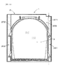
本例は,図17に示すごとく,上記ガラス枠2において,上記一側方部201及び上記他側方部202にガラス枠2を補強するための第1補強用板金271及び第2補強用板金272をそれぞれ設け,上記回動支持部21及び上記枠側ロック部22を上記第1補強用板金271及び第2補強用板金272にそれぞれ設けた例である。
また,上記回動支持部21は,上記一側方部201の上下方向に複数形成されており,上記第1補強用板金271は,複数の上記回動支持部21を連結するよう形成されている。また,上記枠側ロック部22は,上記他側方部202の上下方向に複数形成されており,上記第2補強用板金272は,複数の上記枠側ロック部22を連結するよう形成されている。
【0062】
また,上記第1補強用板金271は,上記一側方部201に沿って上下方向に設けられており,上記第2補強用板金272は,上記他側方部202に沿って上下方向に設けられている。
本例においては,図18に示すごとく,上記ガラスユニット3を上記ガラス枠2に取り付けた際に,上記両側方部201,202の補強用板金271,272とガラスユニット3とが強固に係合し,上記ガラスユニット3の取付構造の強度を向上させることができる。また,本例においては,上記各側方部201,202の各補強用板金271,272とガラスユニット3との係合により十分な取付強度が得られるため,図17に示すごとく,上記ガラス枠2の下方部203及び上方部204に補強用板金を設けることが不要となる。また,本例において,その他は上記実施例1と同様であり,上記実施例1と同様の作用効果を得ることができる。
【図面の簡単な説明】
【図1】実施例1における,ガラスユニットの取付構造を示す図で,ガラス枠の後方側から見た状態で示す後面説明図。
【図2】実施例1における,ガラスユニットの取付構造を示す図で,図1におけるA−A矢視断面説明図。
【図3】実施例1における,ガラスユニットの取付構造を示す図で,図1におけるB−B矢視断面説明図。
【図4】実施例1における,ガラスユニットの取付構造を示す図で,図1におけるC−C矢視断面説明図。
【図5】実施例1における,ガラスユニットの取付構造を示す図で,図1におけるD−D矢視断面説明図。
【図6】実施例1における,ガラスユニットを示す後面説明図。
【図7】実施例1における,ガラス枠を後方側から見た状態で示す後面説明図。
【図8】実施例1における,ガラスユニットを浮上位置に移動させた状態を示す後面説明図。
【図9】実施例1における,ガラスユニットを回動位置に移動させた状態を示す図で,図1におけるC−C矢視相当の断面説明図。
【図10】実施例1における,ガラスユニットを回動位置に移動させた状態を示す図で,図1におけるD−D矢視相当の断面説明図。
【図11】実施例2における,ガラスユニットの取付構造を示す図で,ガラス枠の後方側から見た状態で示す後面説明図。
【図12】実施例2における,ガラスユニットの取付構造を示す図で,図11におけるA−A矢視断面説明図。
【図13】実施例2における,ガラスユニットの取付構造を示す図で,図11におけるB−B矢視断面説明図。
【図14】実施例2における,ガラスユニットの取付構造を示す図で,図11におけるC−C矢視断面説明図。
【図15】実施例2における,ガラスユニットを浮上位置に移動させた状態を示す後面説明図。
【図16】実施例2における,ガラスユニットを回動位置に移動させた状態を示す図で,図11におけるC−C矢視相当の断面説明図。
【図17】実施例3における,ガラス枠を後方側から見た状態で示す後面説明図。
【図18】実施例3における,ガラスユニットの取付構造を示す図で,ガラス枠の後方側から見た状態で示す後面説明図。
【符号の説明】
1...ガラスユニット取付構造(ガラス扉),
101...取付位置,
102...浮上位置,
103...回動位置,
2...ガラス枠,
205...後方側,
21...回動支持部,
22...枠側ロック部,
23...枠側対面部(荷重受け部),
231...スペーサ部,
25...開口穴,
3...ガラスユニット,
30...外縁部,
301...一側方部,
302...他側方部,
303...下方部,
304...上方部,
31...回動ヒンジ部,
32...ユニット側ロック部,
33...ユニット側対面部,
331...スペーサ当接面,
332...スペーサ収納部,
35...ガラス板,
4...上下固定具,
5...枠体,
51...遊技盤,
X...回動中心軸,[0001]
【Technical field】
The present invention relates to a glass unit mounting structure in which a glass unit is detachably mounted on a glass frame.
[0002]
[Prior art]
For example, a pachinko gaming machine has a front frame on which a game board having a game area is mounted, and a glass door arranged to be openable and closable with respect to the front frame.
The glass door is constructed by attaching a glass to a detachable glass unit and attaching the glass unit to a glass frame which is a frame portion of the glass door, instead of directly providing the glass to the glass door. I have. As such a glass door of a pachinko gaming machine, for example, there is one shown in
The glass unit is attached to the glass frame by inserting the pin holes provided in the glass unit into the pins provided in the glass frame and engaging the pins and the pin holes with fasteners and fixing them. ing.
[0003]
[Patent Document 1]
JP-A-7-213691 (FIG. 15, etc.)
[0004]
[Problem to be solved]
However, the pins and the pin holes are formed at a plurality of locations (usually four locations), and it is not always easy to insert each pin into each pin hole at the same time. In addition, when the pins are inserted into the pin holes to perform positioning and then these parts are engaged with the fasteners and fixed, it is necessary to engage a plurality of locations.
Therefore, in the conventional glass door, it takes time to attach the glass unit to the glass frame, and it takes time to remove the glass unit from the glass frame.
[0005]
The present invention has been made in view of such a conventional problem, and an object of the present invention is to provide a glass unit mounting structure in which the glass unit can be easily mounted on and removed from a glass frame.
[0006]
[Means for solving the problem]
The present invention relates to a glass unit mounting structure in which a glass unit is detachably mounted on a glass frame,
The glass unit has a glass plate and an outer edge disposed so as to surround an outer edge of the glass plate. One side of the outer edge has the glass unit with respect to the glass frame. Has a rotating hinge part for rotatably mounting the
The glass frame has an opening hole covered from the rear side by the glass unit, and a rotation support portion that engages with the rotation hinge portion and rotatably supports the rotation hinge portion.
The glass unit and the glass frame are formed with a unit-side facing portion and a frame-side facing portion that face each other in the vertical direction, and the frame-side facing portion faces the lower surface of the unit-side facing portion. Is formed,
A spacer portion protruding toward the other is formed on one of the unit-side facing portion and the frame-side facing portion. On the other side, a spacer contact surface that contacts the spacer portion and the spacer portion are provided. A spacer storage part that can be stored is formed,
The glass unit is rotatable by engagement of the rotating hinge and the rotating support in a state where the spacer is brought into contact with the spacer contact surface and floats with respect to the glass frame. The glass unit is characterized in that when the spacer portion faces the spacer storage portion, the spacer portion is stored in the spacer storage portion and descends with respect to the glass frame. The mounting structure (claim 1).
[0007]
In the mounting structure of the present invention, the glass unit provided with the glass plate and the outer edge has the rotating hinge on one side of the outer edge, and is provided with the opening. The glass frame to be provided has the above-mentioned rotation support portion. After the connection between the glass unit and the glass frame, the glass unit can be freely rotated with respect to the glass frame by the rotation hinge portion and the rotation support portion.
[0008]
The unit side facing part provided on the glass unit and the frame side facing part provided on the glass frame are provided with the spacer part on one side and the spacer contacting surface and the spacer storage part on the other side. is there.
In the present invention, the spacer unit comes into contact with the spacer contact surface, so that the glass unit can be turned while being floated above the glass frame. The glass unit is accommodated in the spacer accommodating portion and descends with respect to the glass frame.
[0009]
That is, when attaching the glass unit to the glass frame, the rotation hinge portion of the glass unit is engaged with the rotation support portion of the glass frame to connect the glass unit and the glass frame. Then, the spacer portion formed on one of the glass unit and the glass frame is brought into contact with the spacer contact surface formed on the other, thereby forming a state in which the glass unit floats above the glass frame. In this floating state, the spacer portion slides on the surface of the spacer contact surface, and the glass unit can turn around the turning hinge portion and the turning support portion with respect to the glass frame. it can.
[0010]
When the glass unit is rotated to an overlapping position where the glass unit completely or almost overlaps with the glass frame, the state of contact between the spacer portion and the spacer contact surface is released, and the glass unit moves with respect to the glass frame. And the spacer portion is stored in the spacer storage portion. That is, when mounting the glass unit in the mounting structure of the present invention, the rotation hinge portion and the rotation support portion are engaged, and thereafter, the glass unit is simply rotated to the overlapping position. The at least rough positioning of the glass unit in which the spacer portion is accommodated in the spacer accommodating portion can be performed.
Further, after the spacer unit is housed in the spacer housing unit, the glass unit can be attached to the glass frame without being fixed with a fastener or the like.
[0011]
On the other hand, when removing the glass unit from the glass frame, the glass unit is lifted and the spacer portion is pulled out from the spacer storage portion. When the glass unit is rotated around the rotation hinge portion and the rotation support portion as a rotation center, the spacer portion comes into contact with the spacer contact surface, and the glass unit rotates in the floating state. Is done. Then, after that, the rotation hinge portion is removed from the rotation support portion, and the glass unit can be removed from the glass frame. Therefore, in the mounting structure of the present invention, it is easy to remove the glass unit from the glass frame.
As described above, in the mounting structure of the present invention, the glass unit can be easily mounted and removed from the glass frame, and the glass unit can be mounted and removed in a short time.
[0012]
BEST MODE FOR CARRYING OUT THE INVENTION
A preferred embodiment of the present invention described above will be described.
In the present invention, the storage of the spacer portion in the spacer storage portion means not only a case where the spacer portion is engaged or fitted with little space between the spacer portion and the spacer storage portion, but also a case where the space portion is slightly spaced. This includes the case of engaging or fitting in the state in which is formed.
In addition, the positioning of the glass unit with respect to the glass frame includes not only positioning in a state where the glass unit is almost completely stopped at the overlapping position, but also positioning in a state where the overlapping position has a certain amount of wobble. Including.
[0013]
In the present invention, it is preferable that a plurality of the spacer portions and the spacer housing portions are formed on the unit-side facing portion and the frame-side facing portion, respectively.
In this case, the glass unit can be floated by the plurality of spacer portions and the spacer contact surface, and the plurality of spacer portions can be stored in the plurality of spacer storage portions to perform the positioning. . Therefore, the floating of the glass unit is easy, and the positioning of the glass unit can be performed stably.
[0014]
It is preferable that the glass unit and the glass frame have a lock portion that engages with each other when the spacer portion is housed in the spacer housing portion.
In this case, the positioning of the glass unit can be further stabilized by the lock unit provided on the glass unit and the glass frame.
[0015]
Further, the lock portion includes a unit-side lock portion provided on the other side portion of the glass unit opposite to the one side portion of the outer edge portion, and the lock portion is engaged with the unit-side lock portion. It is preferable to include a frame-side lock portion provided on the glass frame (claim 4).
In this case, when the positioning of the glass unit is performed, the engagement between the rotation hinge portion and the rotation support portion at one side portion of the outer edge portion and the other side portion of the outer edge portion are performed. Can be engaged with the frame-side lock portion. Therefore, the glass unit is engaged with each part on both the left and right sides, and the positioning of the glass unit can be further stabilized.
[0016]
Further, it is preferable that the rotation support portion and the frame-side lock portion are respectively provided on reinforcing metal plates provided on both side portions of the glass frame.
In this case, when the glass unit is mounted on the glass frame, the reinforcing sheet metal on both sides is firmly engaged with the glass unit, and the strength of the mounting structure of the glass unit can be improved. it can.
[0017]
The unit-side facing portion is formed below the outer edge portion of the glass unit, and the frame-side facing portion is formed so as to face the unit-side facing portion formed at the lower portion. (Claim 6).
In this case, it is easy to provide the unit-side facing portion and the frame-side facing portion in the glass unit and the glass frame.
[0018]
Further, it is preferable that at least one of the spacer section and the spacer accommodating section is provided near a rotation center axis formed by the rotation hinge section and the rotation support section.
In this case, a contact state between the spacer portion and the spacer contact surface can be formed within a wide rotation range of the glass unit with respect to the glass frame.
[0019]
Further, it is preferable that the glass unit or the glass frame has a vertical fixing device for preventing the glass unit from being displaced upward in a state where the spacer portion is housed in the spacer housing portion. (Claim 8).
In this case, the glass unit can be vertically fixed to the glass frame by the vertical fixing device. Therefore, the mounting structure in which the glass unit is mounted on the glass frame can be stably maintained.
[0020]
Preferably, the glass unit has a handle for operating the glass unit (claim 9).
In this case, the glass unit can be easily rotated with respect to the glass frame by operating with the handle. In addition, the glass unit can be easily lifted from the positioned state by operating the handle. Therefore, the work of attaching and detaching the glass unit can be performed more easily.
[0021]
Further, it is preferable that the glass frame has a load receiving portion for receiving a load of the glass unit when the spacer portion is housed in the spacer housing portion.
In this case, the load of the glass unit is received by the load receiving portion, and the positioning state of the glass unit with respect to the glass frame can be stabilized.
[0022]
【Example】
Hereinafter, embodiments of the glass unit mounting structure of the present invention will be described with reference to the drawings.
(Example 1)
The
As shown in FIG. 6, the
[0023]
As shown in FIG. 7, the
As shown in FIGS. 1 and 2, the
[0024]
A
[0025]
As shown in FIGS. 8 and 10, the
[0026]
The details are described below.
Hereinafter, the
In this example, the
[0027]
As shown in FIGS. 2 and 4, the
In this example, the
[0028]
As shown in FIGS. 2 and 4, the
The
[0029]
As shown in FIG. 6, a unit-side first facing
In this example, as shown in FIG. 6, a first
A first projecting
[0030]
Also, as shown in FIG. 6, the turning
[0031]
As shown in FIG. 1, the unit-
The
[0032]
As shown in FIG. 1, the
In addition, the
[0033]
As shown in FIG. 1, the
[0034]
As shown in FIG. 6, the unit-
In this example, as shown in FIG. 6, a second
A second projecting
[0035]
As shown in FIG. 6, the unit-
The
[0036]
As shown in FIGS. 1 and 2, the
As shown in FIG. 7, the upper and
[0037]
Further, as shown in FIG. 7, the
As shown in FIGS. 1 and 3, the
[0038]
Further, as shown in FIGS. 1 and 6, the
[0039]
The
That is, as shown in FIG. 1, in the mounting position 101, the
[0040]
Then, as shown in FIG. 1, in the mounting position 101, the upper and
As shown in FIGS. 1 to 4, at the mounting position 101, the engagement between the
[0041]
As shown in FIG. 8, when the
Further, at the floating position 102, the engagement between the unit-
[0042]
As shown in FIG. 1, in order to form a floating state of the
[0043]
As shown in FIG. 8, when the
In this example, the mounting position 101 and the floating position 102 are overlapping positions where the
[0044]
As shown in FIGS. 9 and 10, the
[0045]
In addition, as shown in FIG. 10, at the rotation position 103, the
Further, when the
[0046]
As described above, in the glass
[0047]
The frame-
In this example, the
[0048]
When attaching the
When the
[0049]
As shown in FIGS. 9 and 10, at the rotation position 103, the
As shown in FIG. 10, the
[0050]
Then, as shown in FIG. 10, when the
Then, as shown in FIG. 5, when the
[0051]
At this time, the
[0052]
As described above, in the glass
[0053]
After the positioning, the upper and
Further, at the mounting position 101, the
[0054]
Therefore, the
[0055]
When removing the
[0056]
Next, as shown in FIGS. 9 and 10, when the
Then, when the
[0057]
Thus, when the
As described above, in the glass
[0058]
(Example 2)
In this example, as shown in FIGS. 11 to 16, the
Note that the
[0059]
Also, as shown in FIGS. 11 and 12, in this example, the
As shown in FIGS. 11 and 12, the upper and
[0060]
Further, as shown in FIG. 11, the
Also in this example, the
[0061]
(Example 3)
In this example, as shown in FIG. 17, a first reinforcing
A plurality of the
[0062]
Further, the first reinforcing
In this example, as shown in FIG. 18, when the
[Brief description of the drawings]
FIG. 1 is a diagram illustrating a mounting structure of a glass unit according to a first embodiment, and is a rear explanatory view illustrating a state seen from a rear side of a glass frame.
FIG. 2 is a diagram illustrating a mounting structure of the glass unit in the first embodiment, and is a cross-sectional explanatory view taken along the line AA in FIG. 1;
FIG. 3 is a diagram illustrating a mounting structure of the glass unit according to the first embodiment, and is a cross-sectional explanatory view taken along line BB in FIG. 1;
FIG. 4 is a diagram showing a mounting structure of the glass unit according to the first embodiment, and is a cross-sectional explanatory view taken along the line CC in FIG. 1;
FIG. 5 is a diagram showing a mounting structure of the glass unit in the first embodiment, and is a cross-sectional explanatory view taken along the line DD in FIG. 1;
FIG. 6 is an explanatory rear view showing the glass unit in the first embodiment.
FIG. 7 is an explanatory rear view showing the glass frame as viewed from the rear side in the first embodiment.
FIG. 8 is an explanatory rear view showing a state in which the glass unit is moved to a floating position in the first embodiment.
FIG. 9 is a diagram illustrating a state in which the glass unit is moved to a rotation position according to the first embodiment, and is a cross-sectional explanatory view corresponding to the arrow CC in FIG. 1;
FIG. 10 is a diagram illustrating a state in which the glass unit is moved to a rotation position according to the first embodiment, and is a cross-sectional explanatory diagram corresponding to the arrow DD in FIG. 1;
FIG. 11 is a diagram illustrating a mounting structure of a glass unit according to the second embodiment, and is a rear explanatory view illustrating a state seen from a rear side of a glass frame.
FIG. 12 is a diagram illustrating a mounting structure of a glass unit according to a second embodiment, and is a cross-sectional explanatory view taken along the line AA in FIG. 11;
FIG. 13 is a view showing a mounting structure of a glass unit according to the second embodiment, and is a cross-sectional explanatory view taken along the line BB in FIG. 11;
FIG. 14 is a diagram illustrating a mounting structure of a glass unit according to the second embodiment, and is a cross-sectional explanatory view taken along the line CC in FIG. 11;
FIG. 15 is a rear view illustrating a state in which the glass unit is moved to a floating position according to the second embodiment.
FIG. 16 is a diagram illustrating a state in which the glass unit is moved to a rotation position according to the second embodiment, and is a cross-sectional explanatory view corresponding to the arrow CC in FIG. 11;
FIG. 17 is an explanatory rear view showing the glass frame as viewed from the rear side in the third embodiment.
FIG. 18 is a diagram illustrating a mounting structure of a glass unit according to a third embodiment, and is a rear explanatory view illustrating a state seen from a rear side of a glass frame.
[Explanation of symbols]
1. . . Glass unit mounting structure (glass door),
101. . . Mounting position,
102. . . Ascent position,
103. . . Pivot position,
2. . . Glass frame,
205. . . Rear side,
21. . . Pivot support,
22. . . Frame side lock,
23. . . Frame side facing part (load receiving part),
231. . . Spacer part,
25. . . Opening hole,
3. . . Glass unit,
30. . . Outer edge,
301. . . One side,
302. . . The other side,
303. . . Lower part,
304. . . Upper part,
31. . . Pivot hinge,
32. . . Unit side lock,
33. . . Facing unit side,
331. . . Spacer contact surface,
332. . . Spacer storage,
35. . . Glass plate,
4. . . Vertical fixture,
5. . . Frame,
51. . . Game board,
X. . . Rotation center axis,
Claims (10)
上記ガラスユニットは,ガラス板と,該ガラス板の外縁を囲うよう配設された外縁部とを有しており,該外縁部の一側方部には,上記ガラス枠に対して上記ガラスユニットを回動可能に取り付けるための回動ヒンジ部を有しており,
上記ガラス枠は,上記ガラスユニットにより後方側から覆われる開口穴と,上記回動ヒンジ部と係合して,これを回動可能に支持する回動支持部とを有しており,
上記ガラスユニット及び上記ガラス枠には,それぞれ互いに上下方向に対面するユニット側対面部及び枠側対面部が形成されていると共に,上記ユニット側対面部の下面に対面するよう上記枠側対面部が形成されており,
上記ユニット側対面部又は上記枠側対面部の一方には,他方に向けて突出したスペーサ部が形成されており,他方には,上記スペーサ部と当接するスペーサ当接面と,上記スペーサ部を収納可能なスペーサ収納部とが形成されており,
上記ガラスユニットは,上記スペーサ部を上記スペーサ当接面に当接させて上記ガラス枠に対して浮上した状態で,上記回動ヒンジ部と上記回動支持部との係合により回動可能であり,上記スペーサ部が上記スペーサ収納部に対向した際には,該スペーサ収納部に上記スペーサ部を収納して上記ガラス枠に対して下降するよう構成してあることを特徴とするガラスユニットの取付構造。In a glass unit mounting structure in which a glass unit is detachably mounted on a glass frame,
The glass unit has a glass plate and an outer edge disposed so as to surround an outer edge of the glass plate. One side of the outer edge has the glass unit with respect to the glass frame. Has a rotating hinge part for rotatably mounting the
The glass frame has an opening hole covered from the rear side by the glass unit, and a rotation support portion that engages with the rotation hinge portion and rotatably supports the rotation hinge portion.
The glass unit and the glass frame are formed with a unit-side facing portion and a frame-side facing portion that face each other in the vertical direction, and the frame-side facing portion faces the lower surface of the unit-side facing portion. Is formed,
A spacer portion protruding toward the other is formed on one of the unit-side facing portion and the frame-side facing portion. On the other side, a spacer contact surface that contacts the spacer portion and the spacer portion are provided. A spacer storage part that can be stored is formed,
The glass unit is rotatable by engagement of the rotating hinge and the rotating support in a state where the spacer is brought into contact with the spacer contact surface and floats with respect to the glass frame. The glass unit is characterized in that when the spacer portion faces the spacer storage portion, the spacer portion is stored in the spacer storage portion and descends with respect to the glass frame. Mounting structure.
Priority Applications (1)
| Application Number | Priority Date | Filing Date | Title |
|---|---|---|---|
| JP2003012685A JP4334874B2 (en) | 2003-01-21 | 2003-01-21 | Glass door structure |
Applications Claiming Priority (1)
| Application Number | Priority Date | Filing Date | Title |
|---|---|---|---|
| JP2003012685A JP4334874B2 (en) | 2003-01-21 | 2003-01-21 | Glass door structure |
Publications (3)
| Publication Number | Publication Date |
|---|---|
| JP2004222865A true JP2004222865A (en) | 2004-08-12 |
| JP2004222865A5 JP2004222865A5 (en) | 2006-03-09 |
| JP4334874B2 JP4334874B2 (en) | 2009-09-30 |
Family
ID=32901218
Family Applications (1)
| Application Number | Title | Priority Date | Filing Date |
|---|---|---|---|
| JP2003012685A Expired - Fee Related JP4334874B2 (en) | 2003-01-21 | 2003-01-21 | Glass door structure |
Country Status (1)
| Country | Link |
|---|---|
| JP (1) | JP4334874B2 (en) |
Cited By (7)
| Publication number | Priority date | Publication date | Assignee | Title |
|---|---|---|---|---|
| JP2006087611A (en) * | 2004-09-22 | 2006-04-06 | Sanyo Product Co Ltd | Method of manufacturing transparent panel assembly for game machine |
| JP2006296586A (en) * | 2005-04-18 | 2006-11-02 | Samii Kk | Game machine |
| JP2006333932A (en) * | 2005-05-31 | 2006-12-14 | Juki Corp | Glass holding mechanism of game machine |
| JP2007029476A (en) * | 2005-07-27 | 2007-02-08 | Daiichi Shokai Co Ltd | Glass door for game machine |
| JP2007130230A (en) * | 2005-11-10 | 2007-05-31 | Heiwa Corp | Game machine frame of pachinko game machine |
| JP2010234090A (en) * | 2010-07-26 | 2010-10-21 | Sanyo Product Co Ltd | Method for manufacturing transparent panel assembly for game machine |
| JP2011234905A (en) * | 2010-05-11 | 2011-11-24 | Sanyo Product Co Ltd | Game machine |
-
2003
- 2003-01-21 JP JP2003012685A patent/JP4334874B2/en not_active Expired - Fee Related
Cited By (7)
| Publication number | Priority date | Publication date | Assignee | Title |
|---|---|---|---|---|
| JP2006087611A (en) * | 2004-09-22 | 2006-04-06 | Sanyo Product Co Ltd | Method of manufacturing transparent panel assembly for game machine |
| JP2006296586A (en) * | 2005-04-18 | 2006-11-02 | Samii Kk | Game machine |
| JP2006333932A (en) * | 2005-05-31 | 2006-12-14 | Juki Corp | Glass holding mechanism of game machine |
| JP2007029476A (en) * | 2005-07-27 | 2007-02-08 | Daiichi Shokai Co Ltd | Glass door for game machine |
| JP2007130230A (en) * | 2005-11-10 | 2007-05-31 | Heiwa Corp | Game machine frame of pachinko game machine |
| JP2011234905A (en) * | 2010-05-11 | 2011-11-24 | Sanyo Product Co Ltd | Game machine |
| JP2010234090A (en) * | 2010-07-26 | 2010-10-21 | Sanyo Product Co Ltd | Method for manufacturing transparent panel assembly for game machine |
Also Published As
| Publication number | Publication date |
|---|---|
| JP4334874B2 (en) | 2009-09-30 |
Similar Documents
| Publication | Publication Date | Title |
|---|---|---|
| JP2004357858A (en) | Attachment/detachment facilitating mechanism for game board | |
| JP2008018052A (en) | Game machine | |
| JP2004222865A (en) | Mounting structure of glass unit | |
| JP2003250960A (en) | Slot machine | |
| JP5976296B2 (en) | Door mounting structure and mounting method | |
| JP2004016355A (en) | Hinge for game machine | |
| JP2004016251A (en) | Securely holding mechanism for game board | |
| JP4836184B2 (en) | Game machine | |
| JP3884937B2 (en) | Board mounting structure for ball game machines | |
| JP3475127B2 (en) | Pachinko machine | |
| JP4510606B2 (en) | Hinge for game console | |
| JP2673441B2 (en) | Pachinko machine | |
| JP4883761B2 (en) | Game machine | |
| JP2003265811A (en) | Coming-off preventing of board housing body in game machine | |
| JP2008207033A (en) | Game machine | |
| JP2008207028A (en) | Game machine | |
| JP4512760B2 (en) | Game machine | |
| JP2005021616A (en) | Pachinko game machine | |
| JP2005046381A (en) | Mounting structure of game board in pachinko game machine, and engagement member of game board | |
| JP2003199951A (en) | Pachinko game machine | |
| JP2000237425A (en) | Window frame of pachinko game machine | |
| JPH1176512A (en) | Pachinko game machine | |
| JP4029293B2 (en) | Locking device for game board in pachinko machine | |
| JP4232141B2 (en) | Board layout structure for gaming machines | |
| JP2004024295A (en) | Temporary support mechanism of game board |
Legal Events
| Date | Code | Title | Description |
|---|---|---|---|
| A521 | Written amendment |
Free format text: JAPANESE INTERMEDIATE CODE: A523 Effective date: 20060118 |
|
| A621 | Written request for application examination |
Free format text: JAPANESE INTERMEDIATE CODE: A621 Effective date: 20060118 |
|
| A977 | Report on retrieval |
Free format text: JAPANESE INTERMEDIATE CODE: A971007 Effective date: 20081224 |
|
| A131 | Notification of reasons for refusal |
Free format text: JAPANESE INTERMEDIATE CODE: A131 Effective date: 20090120 |
|
| A521 | Written amendment |
Free format text: JAPANESE INTERMEDIATE CODE: A523 Effective date: 20090310 |
|
| TRDD | Decision of grant or rejection written | ||
| A01 | Written decision to grant a patent or to grant a registration (utility model) |
Free format text: JAPANESE INTERMEDIATE CODE: A01 Effective date: 20090623 |
|
| A01 | Written decision to grant a patent or to grant a registration (utility model) |
Free format text: JAPANESE INTERMEDIATE CODE: A01 |
|
| A61 | First payment of annual fees (during grant procedure) |
Free format text: JAPANESE INTERMEDIATE CODE: A61 Effective date: 20090624 |
|
| FPAY | Renewal fee payment (event date is renewal date of database) |
Free format text: PAYMENT UNTIL: 20120703 Year of fee payment: 3 |
|
| R150 | Certificate of patent or registration of utility model |
Free format text: JAPANESE INTERMEDIATE CODE: R150 |
|
| FPAY | Renewal fee payment (event date is renewal date of database) |
Free format text: PAYMENT UNTIL: 20120703 Year of fee payment: 3 |
|
| FPAY | Renewal fee payment (event date is renewal date of database) |
Free format text: PAYMENT UNTIL: 20150703 Year of fee payment: 6 |
|
| R250 | Receipt of annual fees |
Free format text: JAPANESE INTERMEDIATE CODE: R250 |
|
| LAPS | Cancellation because of no payment of annual fees |