JP2004221908A - Method for controlling display, photographed image output sysetm capable of using the method, display control device, liquid crystal projector, and digital camera - Google Patents
Method for controlling display, photographed image output sysetm capable of using the method, display control device, liquid crystal projector, and digital camera Download PDFInfo
- Publication number
- JP2004221908A JP2004221908A JP2003006453A JP2003006453A JP2004221908A JP 2004221908 A JP2004221908 A JP 2004221908A JP 2003006453 A JP2003006453 A JP 2003006453A JP 2003006453 A JP2003006453 A JP 2003006453A JP 2004221908 A JP2004221908 A JP 2004221908A
- Authority
- JP
- Japan
- Prior art keywords
- image
- display
- imaging device
- display system
- wireless communication
- Prior art date
- Legal status (The legal status is an assumption and is not a legal conclusion. Google has not performed a legal analysis and makes no representation as to the accuracy of the status listed.)
- Pending
Links
Images


Classifications
-
- H—ELECTRICITY
- H04—ELECTRIC COMMUNICATION TECHNIQUE
- H04N—PICTORIAL COMMUNICATION, e.g. TELEVISION
- H04N1/00—Scanning, transmission or reproduction of documents or the like, e.g. facsimile transmission; Details thereof
- H04N1/00127—Connection or combination of a still picture apparatus with another apparatus, e.g. for storage, processing or transmission of still picture signals or of information associated with a still picture
- H04N1/00281—Connection or combination of a still picture apparatus with another apparatus, e.g. for storage, processing or transmission of still picture signals or of information associated with a still picture with a telecommunication apparatus, e.g. a switched network of teleprinters for the distribution of text-based information, a selective call terminal
- H04N1/00283—Connection or combination of a still picture apparatus with another apparatus, e.g. for storage, processing or transmission of still picture signals or of information associated with a still picture with a telecommunication apparatus, e.g. a switched network of teleprinters for the distribution of text-based information, a selective call terminal with a television apparatus
-
- G—PHYSICS
- G06—COMPUTING OR CALCULATING; COUNTING
- G06F—ELECTRIC DIGITAL DATA PROCESSING
- G06F3/00—Input arrangements for transferring data to be processed into a form capable of being handled by the computer; Output arrangements for transferring data from processing unit to output unit, e.g. interface arrangements
- G06F3/14—Digital output to display device ; Cooperation and interconnection of the display device with other functional units
-
- H—ELECTRICITY
- H04—ELECTRIC COMMUNICATION TECHNIQUE
- H04N—PICTORIAL COMMUNICATION, e.g. TELEVISION
- H04N5/00—Details of television systems
- H04N5/74—Projection arrangements for image reproduction, e.g. using eidophor
-
- H—ELECTRICITY
- H04—ELECTRIC COMMUNICATION TECHNIQUE
- H04N—PICTORIAL COMMUNICATION, e.g. TELEVISION
- H04N2201/00—Indexing scheme relating to scanning, transmission or reproduction of documents or the like, and to details thereof
- H04N2201/0008—Connection or combination of a still picture apparatus with another apparatus
- H04N2201/0015—Control of image communication with the connected apparatus, e.g. signalling capability
-
- H—ELECTRICITY
- H04—ELECTRIC COMMUNICATION TECHNIQUE
- H04N—PICTORIAL COMMUNICATION, e.g. TELEVISION
- H04N2201/00—Indexing scheme relating to scanning, transmission or reproduction of documents or the like, and to details thereof
- H04N2201/0008—Connection or combination of a still picture apparatus with another apparatus
- H04N2201/0034—Details of the connection, e.g. connector, interface
- H04N2201/0037—Topological details of the connection
- H04N2201/0041—Point to point
-
- H—ELECTRICITY
- H04—ELECTRIC COMMUNICATION TECHNIQUE
- H04N—PICTORIAL COMMUNICATION, e.g. TELEVISION
- H04N2201/00—Indexing scheme relating to scanning, transmission or reproduction of documents or the like, and to details thereof
- H04N2201/0008—Connection or combination of a still picture apparatus with another apparatus
- H04N2201/0034—Details of the connection, e.g. connector, interface
- H04N2201/0037—Topological details of the connection
- H04N2201/0043—Point to multipoint
-
- H—ELECTRICITY
- H04—ELECTRIC COMMUNICATION TECHNIQUE
- H04N—PICTORIAL COMMUNICATION, e.g. TELEVISION
- H04N2201/00—Indexing scheme relating to scanning, transmission or reproduction of documents or the like, and to details thereof
- H04N2201/0008—Connection or combination of a still picture apparatus with another apparatus
- H04N2201/0034—Details of the connection, e.g. connector, interface
- H04N2201/0044—Connecting to a plurality of different apparatus; Using a plurality of different connectors
-
- H—ELECTRICITY
- H04—ELECTRIC COMMUNICATION TECHNIQUE
- H04N—PICTORIAL COMMUNICATION, e.g. TELEVISION
- H04N2201/00—Indexing scheme relating to scanning, transmission or reproduction of documents or the like, and to details thereof
- H04N2201/0008—Connection or combination of a still picture apparatus with another apparatus
- H04N2201/0034—Details of the connection, e.g. connector, interface
- H04N2201/0048—Type of connection
- H04N2201/0055—By radio
-
- H—ELECTRICITY
- H04—ELECTRIC COMMUNICATION TECHNIQUE
- H04N—PICTORIAL COMMUNICATION, e.g. TELEVISION
- H04N2201/00—Indexing scheme relating to scanning, transmission or reproduction of documents or the like, and to details thereof
- H04N2201/0077—Types of the still picture apparatus
- H04N2201/0084—Digital still camera
Landscapes
- Engineering & Computer Science (AREA)
- Human Computer Interaction (AREA)
- Theoretical Computer Science (AREA)
- Multimedia (AREA)
- Signal Processing (AREA)
- Physics & Mathematics (AREA)
- General Engineering & Computer Science (AREA)
- General Physics & Mathematics (AREA)
- Studio Devices (AREA)
- Controls And Circuits For Display Device (AREA)
- Closed-Circuit Television Systems (AREA)
Abstract
Description
【0001】
【発明の属する技術分野】
本発明は、表示制御方法とこの方法を利用可能な撮影画像出力システム、表示制御装置、液晶プロジェクタ、およびデジタルカメラに関する。本発明は特に、撮影した画像を無線ネットワーク経由で送信する技術に関する。
【0002】
【従来の技術】
画像をスクリーンに投影する液晶プロジェクタなどの表示装置は、従来、主にビジネスおよび学術向けの装置としてプレゼンテーションや研究発表などに利用されてきた。しかし近年、DVDの普及とともにホームシアター向けの製品として低価格の液晶プロジェクタが次々に開発されている。このような低価格化の流れは、学校教育の場において授業への液晶プロジェクタの導入を容易にしつつある。
【0003】
一方、液晶プロジェクタで投影するコンテンツとして、デジタルカメラにより撮影した画像が多く用いられる。最近では、パーソナルコンピュータを介さずにデジタルカメラを直に液晶プロジェクタへ接続して画像を表示させる技術が提案されている(例えば、特許文献1参照。)。
【0004】
【特許文献1】
特開平11−317898号公報 (全文)
【0005】
【発明が解決しようとする課題】
しかしながら、上記従来技術によればデジタルカメラと液晶プロジェクタを直接接続することから、デジタルカメラ内の画像を液晶プロジェクタで表示させたりその画像を切り替える作業の間、操作者は液晶プロジェクタの側から離れることができなかった。したがって、デジタルカメラを液晶プロジェクタに接続したまま画像を撮影しようとしても撮影範囲は液晶プロジェクタ近辺に限定されてしまい不便であった。また、操作者の位置が液晶プロジェクタ近辺に限定されるので、複数人で代わる代わる操作したい場合は作業が煩雑となる。したがって、学校教育の場で複数の生徒にそれぞれの画像を発表させるといった活用方法には必ずしも向かなかった。
【0006】
本発明はこうした状況に鑑みなされたものであり、その目的はプロジェクタを利用してデジタルカメラ内の画像を表示させる上での利便性を高める点にある。本発明の別の目的は、プロジェクタとデジタルカメラの組み合わせにおける新たな活用法を提案する点にある。
【0007】
【課題を解決するための手段】
本発明のある態様は表示制御方法である。この方法は、送信すべき撮影画像の仕様を撮像装置と表示システムの間で表示能力に基づいて画定するステップと、その仕様に適合した撮影画像を撮像装置から表示システムへ無線通信経由で送信するステップと、送信された画像を表示システムで受信して表示するステップと、を有する。本態様によると、表示システムの表示能力に適合する画像が撮像装置から送信される。したがって、画像の解像度やファイル形式を手動で設定することなく簡単に最適な画像を表示させることができる。
【0008】
本発明の別の態様は撮影画像出力システムである。このシステムは、被写体の画像を撮影してその画像を無線通信経由で送信する撮像装置と、送信された画像を無線通信経由で受信してその画像を表示する表示システムと、を備える。また、画像の送信に先立ち、送信すべき画像の仕様を表示システムの表示能力に基づいて表示システムと撮像装置の間で画定する。画像を送信する直前に仕様を画定してもよいし、画像の撮影より前に仕様を画定してもよい。例えば撮像装置の電源投入時に画定してもよい。画像撮影前に仕様を画定した場合、撮像装置はその仕様に最適な条件で撮影してもよい。表示システムが撮像装置へ表示能力の情報を送って撮像装置側で仕様を選択することによって画定してもよいし、逆に撮像装置が表示システムへ撮像能力の情報を送って表示システム側で選択することによって画定してもよい。本態様においても表示システムの表示能力に適合する画像が撮像装置から送信される。したがって、画像の解像度やファイル形式を手動で設定することなく簡単に最適な画像を表示させることができる。
【0009】
本発明のさらに別の態様は表示制御方法である。この方法は、被写体の画像を撮影するステップと、撮影した画像をその撮影を契機として撮像装置から外部の表示システムへ無線通信経由で送信するステップと、撮影した画像を撮像装置が内蔵する表示部と表示システムでほぼ同時に表示させるステップと、を有する。
本態様によると、撮像装置により撮影した画像は手動で送信指示しなくとも自動的に表示システムに送信され直ちに表示される。したがって、撮像装置の操作者すなわち撮影者は煩わしい操作をすることなく簡単に撮像装置内の画像を表示システムに表示させることができる。また、撮像装置が内蔵する表示部の代用として表示システムを使用することもでき、その操作性や再生の即時性を損なわない。
【0010】
本発明のさらに別の態様は撮影画像出力システムである。このシステムは、被写体の画像を撮影してその画像を無線通信経由で送信する撮像装置と、送信された画像を無線通信経由で受信してその画像を表示する表示システムと、を備える。また、撮影した画像をその撮影を契機として撮像装置が内蔵する表示部と表示システムでほぼ同時に表示させる。本態様においても撮影した画像が自動的に表示システムに送信されて直ちに表示される。したがって、簡単に撮像装置内の画像を表示システムに表示させることができ、その操作性や再生の即時性を損なわない。
【0011】
本発明のさらに別の態様は表示制御方法である。この方法は、撮像装置が内蔵する表示部への表示が指示された画像を撮像装置で読み出すステップと、読み出された画像をその読出を契機として撮像装置から外部の表示システムへ無線通信経由で送信するステップと、表示が指示された画像を表示部と表示システムでほぼ同時に表示させるステップと、を有する。本態様によると、撮像装置の表示部で再生する画像は手動で送信指示しなくとも自動的に表示システムへ直ちに送信され表示される。したがって、撮像装置の操作者は煩わしい操作をすることなく簡単に撮像装置内の画像を表示システムに表示させることができる。また、撮像装置が内蔵する表示部の代用として表示システムを使用することもでき、その操作性や再生の即時性を損なわない。
【0012】
本発明のさらに別の態様は撮影画像出力システムである。このシステムは、撮影画像を読み出してその画像を無線通信経由で送信する撮像装置と、送信された画像を無線通信経由で受信してその画像を表示する表示システムと、を備える。
また、読み出された画像をその読出を契機として撮像装置が内蔵する表示部と表示システムでほぼ同時に表示させる。本態様においても撮像装置の表示部で再生する画像が自動的に表示システムへ直ちに送信されて表示される。したがって、簡単に撮像装置内の画像を表示システムに表示させることができ、その操作性や再生の即時性を損なわない。
【0013】
本発明のさらに別の態様は表示制御方法である。この方法は、無線通信可能な複数の表示システムを認識するステップと、撮影画像を無線通信経由で送信する送信先として複数の表示システムからいずれかを選択するステップと、撮影画像をその撮影を契機として前記選択した表示システムへ無線通信経由で送信するステップと、を有する。本態様によると、1台の撮像装置を複数台の表示システムへ接続でき、また表示先を複数の表示システムから選択できる。複数台の撮像装置を複数台の表示システムに接続することもできる。したがって、表示システムと撮像装置の組み合わせに柔軟性を持たせて用途を広げることができる。
【0014】
本発明のさらに別の態様は撮影画像出力システムである。このシステムは、被写体の画像を撮影してその画像を無線通信経由で送信する撮像装置と、画像を無線通信経由で受信してその画像を表示する複数の表示システムと、を備える。また、撮像装置は、送信に先立って画像の送信先として複数の表示システムを認識し、その認識した複数の表示システムからいずれかを選択し、選択した表示システムに対して撮影した画像をその撮影を契機として無線通信経由で送信する。例えば撮影画像の解像度に応じて表示先を選択してもよいし、連写時に各画像を別々の表示先を選択してもよい。本態様においても1台の撮像装置を複数の表示システムへ選択的に表示でき、表示システムと撮像装置を柔軟に組み合わせられる。
【0015】
本発明のさらに別の態様は表示制御方法である。この方法は、無線通信可能な複数の撮像装置を認識するステップと、撮影画像を無線通信経由で送信させる送信元として複数の撮像装置からいずれかを選択するステップと、選択した撮像装置により被写体の画像を撮影するステップと、撮影した画像をその撮影を契機として表示システムへ無線通信経由で送信するステップと、を有する。本態様によると、複数台の撮像装置を1台の表示システムへ接続でき、一定の規則の下で交互に各撮像装置から表示システムへ画像を送信して表示できる。複数台の撮像装置を複数台の表示システムに接続することもできる。したがって、表示システムと撮像装置の組み合わせに柔軟性を持たせて用途を広げることができる。
【0016】
本発明のさらに別の態様は撮影画像出力システムである。このシステムは、被写体の画像を撮影してその画像を無線通信経由で送信する複数の撮像装置と、画像を無線通信経由で受信してその画像を表示する表示システムと、を備える。また、表示システムは、受信に先立って画像の送信元として複数の撮像装置を認識し、その認識した複数の撮像装置からいずれかを選択し、選択した撮像装置から前記撮影された画像をその撮影を契機として無線通信経由で受信する。本態様においても複数台の撮像装置を1台の表示システムに接続して交互に画像を表示でき、表示システムと撮像装置を柔軟に組み合わせることができる。
【0017】
本発明のさらに別の態様は表示制御方法である。この方法は、撮像装置から表示システムへ撮影画像を無線通信経由で送信して表示させるのに先立ち、その撮影画像の表示の可否を所定の許可条件に基づいて決定するステップと、決定により表示が許可された撮影画像を前記表示システムにより表示するステップと、を有する。許可条件は、撮影画像ごとの表示可否を定めてもよいし、撮像装置ごとの表示可否を定めてもよい。本態様によると、表示システムに画像を表示させるタイミングや表示の対象を制限できる。したがって、撮像装置側から送られてくる表示対象を表示システム側で制限または管理できる。
【0018】
本発明のさらに別の態様は撮影画像出力システムである。このシステムは、被写体の画像を撮影してその画像を無線通信経由で送信する撮像装置と、送信された画像を無線通信経由で受信してその画像を表示する表示システムと、を備える。また、表示システムは、送信される画像に関して表示の可否を所定の許可条件に基づいて決定するとともに、決定によって表示を許可した場合に限り前記送信される画像を表示する。表示可否を自動的に決定するよう定めてもよいし、表示システムの操作者により手動で決定するよう定めてもよい。表示の可否にかかわらず画像の受信を許可することとしてもよいし、表示が許可されない限り画像の受信を拒否することとしてもよい。本態様においても表示システムへの表示対象を表示システム側で制御できる。
【0019】
本発明のさらに別の態様は表示制御方法である。この方法は、撮像装置と表示システムの間における無線通信の接続状況に関する情報を検出するステップと、接続状況に関する情報を撮像装置および表示システムのうち少なくともいずれかにより表示するステップと、を有する。本態様によると、撮像装置と表示システムの間で無線通信の確立状態、画像送信の状態、無線電波の状態、などを表示システムまたは撮像装置のいずれか、あるいは、表示システムおよび撮像装置の双方に表示できる。したがって、撮像装置の通信相手をその通信状態にかかわらず容易に把握できる。また、撮像装置が内蔵する表示部の代用として表示システムを利用できる。
【0020】
本発明のさらに別の態様は撮影画像出力システムである。このシステムは、被写体の画像を撮影してその画像を無線通信経由で送信する撮像装置と、画像を無線通信経由で受信してその画像を表示する表示システムと、を備える。また、撮像装置および表示システムのうち少なくともいずれかが、撮像装置と表示システムの間における無線通信の接続状況に関する情報を検出して表示する。本態様においても撮像装置と表示システムの間でなされている通信の状態を表示システムまたは撮像装置のいずれか、あるいは、表示システムおよび撮像装置の双方に表示でき、通信の状態を容易に把握できる。
【0021】
本発明のさらに別の態様は表示制御方法である。この方法は、撮像装置から表示システムへ無線通信経由で送信する撮影画像の前記表示システムにおける表示の可否を決定するステップと、表示の可否に関する情報を表示システムにより表示するステップと、を有する。表示の可否は、特定の撮像装置に対する表示の可否であってもよいし、特定のタイミングにおける表示の可否であってもよい。本態様によると、表示システムにおいてなされている表示の制限内容が表示される。したがって、表示システムにおいて許可された表示対象を明確にでき、撮影装置側からもその対象を容易に把握できる。
【0022】
本発明のさらに別の態様は撮影画像出力システムである。このシステムは、被写体の画像を撮影してその画像を無線通信経由で送信する撮像装置と、画像を無線通信経由で受信してその画像を表示する表示システムと、を備える。また、表示システムは、撮像装置で撮影された画像の表示システムにおける表示の可否を決定し、決定された表示の可否に関する情報を表示する。本態様においても表示システムにおける表示の制限内容を容易に把握できる。
【0023】
本発明のさらに別の態様は表示制御方法である。この方法は、撮像装置と表示システムの間で無線通信を確立するために必要な設定情報を視覚的に表現した設定画像を生成するステップと、設定画像を表示するステップと、表示された設定画像を被写体とした画像を撮影するステップと、撮影した画像に基づいて設定情報を認識するステップと、認識した設定情報に基づいて撮像装置と表示システムの間で無線通信を確立するステップと、を有する。本態様によると、撮像装置と表示システムの間でそれぞれの機能を利用することにより、手動の設定操作をしなくとも自動的に通信が確立される。したがって、煩雑な設定作業をすることなく簡単に撮像装置と表示システムを接続できる。
【0024】
本発明のさらに別の態様は撮影画像出力システムである。このシステムは、被写体の画像を撮影してその画像を無線通信経由で送信する撮像装置と、画像を無線通信経由で受信してその画像を表示する表示システムと、を備える。また、表示システムは、撮像装置との無線通信の確立に必要な設定情報を視覚的に表現した設定画像を生成してこれを表示する。撮像装置は、表示された設定画像を被写体とした画像を撮影し、撮影した画像に基づいて設定情報を認識し、認識した設定情報に基づいて表示システムとの無線通信を確立する。本態様においても煩雑な設定作業をすることなく自動的に撮像装置と表示システムを接続できる。
【0025】
なお、以上の構成要素の任意の組合せや、本発明の構成要素や表現を方法、装置、システム、コンピュータプログラム、プログラムを格納した記録媒体、データ構造などの間で相互に置換したものもまた、本発明の態様として有効である。
【0026】
【発明の実施の形態】
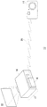
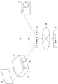
図1は、撮影画像出力システム10の基本的な構成を示す。撮像装置18で撮影した画像は無線通信20を介して表示システム12の表示制御装置16へ送信される。表示制御装置16は受信した画像を表示システム12の表示装置14へ入力する。表示装置14は入力された画像をスクリーンへ投影する。投影画面22には撮像装置18で撮影されたばかりの画像が即座に表示される。
【0027】
撮像装置18は、例えば無線LAN機能を搭載したデジタルスチルカメラである。無線通信20としては、主にIEEE802.11a/b/gなどの無線LAN通信やBluetooth(商標)などの通信方式がある。表示システム12は、表示装置14と表示制御装置16で構成される。表示装置14として液晶プロジェクタを例示するが、テレビジョン受像機を用いてもよい。表示制御装置16は、例えば無線LAN機能と画像信号変換機能を内蔵した装置であり、液晶プロジェクタの画像入力端子に接続するオプション装置である。ただし、表示制御装置16を表示装置14に内蔵させて表示システム12を構成してもよい。
【0028】
撮像装置18および表示制御装置16の構成は、ハードウエア的には、CPU、メモリ、通信モジュール、その他のLSIで実現でき、ソフトウエア的にはメモリにロードされたデータ送受信機能や画像処理機能のあるプログラムなどによって実現されるが、図2以降ではそれらの連携によって実現される機能ブロックを描いている。したがって、これらの機能ブロックがハードウエアのみ、ソフトウエアのみ、またはそれらの組合せによっていろいろな形で実現できることは、当業者には理解されるところである。
【0029】
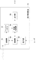
図2は、表示制御装置16の基本構成を示す機能ブロック図である。表示制御装置16は、通信部50、バッファメモリ52、制御部54、画像処理部56、出力部58、および操作部60を有する。各部は通信部50を介して外部と通信する。通信部50は撮像装置18から画像を受信してバッファメモリ52に格納する。バッファメモリ52はJPEG形式やMPEG形式などで圧縮された静止画または動画のデータを一時的に記憶するRAMである。画像処理部56はバッファメモリ52から画像を読み出し、復号処理や映像信号変換処理を施して映像データを生成する。出力部58は画像処理部56が生成した映像データを表示装置14の映像入力端子へ出力する。制御部54は、通信部50や画像処理部56などの各部の動作を制御する。操作部60はユーザからの操作を受け付け、その操作に応じた命令を制御部54へ送る。
【0030】
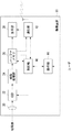
図3は、撮像装置18の基本構成を示す機能ブロック図である。撮像装置18は、レンズ30、CCD32、画像処理部34、バッファメモリ36、表示部38、制御部40、通信部42、および操作部44を有する。レンズ30は被写体からの光を取り込んで結像し、CCD32は結像された像を電気信号に変換する。画像処理部34は電気信号をA/D変換し、これを圧縮処理してバッファメモリ36に格納する。バッファメモリ36は、JPEG形式やMPEG形式などで圧縮された静止画または動画のデータを一時的に記憶するRAMである。表示部38は、バッファメモリ36に格納された画像を表示部38の画面に表示する。
通信部42は無線通信を介して表示制御装置16へ画像を送信する。各部は通信部42を介して外部と通信する。制御部40は、CCD32、表示部38、通信部42などの各部の動作を制御する。操作部44はユーザからの操作を受け付け、その操作に応じた命令を制御部40へ送る。
【0031】
図4は、表示制御装置16の制御部54の詳細な構成を示す機能ブロック図である。制御部54は、仕様設定部90、再生制御部92、対象設定部94、通信設定部96、状態表示部98、および設定画像生成部99を含む。仕様設定部90は撮像装置18から受信すべき画像の仕様を画定し、再生制御部92は表示装置14への画像の出力を制御する。対象設定部94は表示システム12によって表示する画像の対象を設定し、通信設定部96は撮像装置18との無線通信を制御する。状態表示部98は通信状態などの各種情報を表示装置14へ出力し、設定画像生成部99は撮像装置18が表示制御装置16と無線通信を確立するために必要な情報を出力する。各構成の詳細な機能については後述する。
【0032】
図5は、撮像装置18の制御部40の詳細な構成を示す機能ブロック図である。制御部40は、仕様設定部70、転送処理部72、再生制御部74、撮影制御部76、通信設定部78、状態表示部80、および設定認識部82を含む。仕様設定部70は表示制御装置16へ送信すべき画像の仕様を画定し、転送処理部72は表示制御装置16への画像の送信を制御する。再生制御部74は表示部38による画像の再生を制御し、撮影制御部76はCCD32による画像の撮影を制御する。通信設定部78は表示制御装置16と無線通信を確立するために必要な情報を設定し、状態表示部80は通信状態などの各種情報を表示部38へ表示させる。各構成の詳細な機能については後述する。
【0033】
以下、撮影画像出力システム10が有する機能を順に説明する。
第1の機能は、表示する画像の仕様を画定する機能である。図4の仕様設定部90はあらかじめ表示システム12の表示能力を記憶する。表示能力は、例えばVGA、XGA、SXGAなどの解像度やJPEG、TIFFなどのファイル形式で示される。仕様設定部90は、表示システム12で表示可能な画像の仕様として表示システム12の表示能力のデータを撮像装置18へ送信する。図5の仕様設定部70は図4の仕様設定部90から画像の仕様に関するデータを取得する。仕様設定部70はあらかじめ撮像装置18の撮像能力を記憶する。撮像能力は、例えば撮影可能な画像の解像度やJPEG、TIFFなどのファイル形式で示される。仕様設定部70は、仕様設定部90から取得した表示能力と撮像装置18の撮像能力を比較し、能力の調停を図る。例えば解像度やファイル形式に共通する仕様があればその仕様を採用し、共通する仕様がなければ表示能力に適合するよう画像を変換する。共通する仕様が複数ある場合は、より画質の高い仕様を採用してもよい。これら能力の調停は、撮像装置18の電源投入時に表示システム12との間で実行してもよい。
【0034】
図6は、撮影画像を撮像装置18から表示制御装置16へ送信する過程を示すフローチャートである。撮像装置18が画像を撮影し(S10)、表示制御装置16へ撮影画像の送信許可要求を送ると(S12)、表示制御装置16は要求に対する応答として許可通知と表示可能な画像の仕様を撮像装置18へ送る(S14)。撮像装置18は表示制御装置16へ送信すべき画像の仕様を撮像能力に照らして画定し(S16)、必要に応じて画像を変換する(S18)。撮像装置18が表示制御装置16へ画像を送信し(S20)、表示制御装置16がACK応答を撮像装置18へ送り返すと(S22)、画像の転送が終了する。以降のフローに関しては後述する。
【0035】
第2の機能は、撮影画像をその撮影直後に撮像装置18の表示部38と表示制御装置16が同時に表示する機能である。図5の撮影制御部76の制御の下で画像が撮影されるとき、その撮影を契機として転送処理部72は撮影画像を直ちに表示制御装置16へ送信するよう制御する。表示制御装置16への画像送信が完了したとき、表示部38に画像の表示を指示する。図4の再生制御部92は撮像装置18から受信した画像を直ちに表示装置14へ出力するよう制御する。これにより、撮像装置18のユーザが何ら指示をしなくとも撮影画像が表示部38と表示システム12でほぼ同時に表示される。
【0036】
図6において、上述した通りS10からS22までの過程によって撮像装置18から表示制御装置16へ画像が送信された後、撮像装置18の表示部38と表示システム12はほぼ同時に同じ画像を表示する(S26、S28)。
【0037】
第3の機能は、撮像装置18の表示部38で再生する画像を表示システム12でも同時に表示する機能である。撮像装置18のユーザから操作部44を介して画像の再生が指示されたとき、図5の再生制御部74は再生対象の画像を読み出す処理を制御する。読出先はバッファメモリ36または外部のサーバである。外部のサーバに格納された画像を再生する場合はその画像を通信部42が受信する。転送処理部72は、画像の読出を契機としてその読み出された画像を表示制御装置16へ直ちに送信するよう制御する。再生制御部74は、表示制御装置16への画像送信が完了したときに表示部38に画像の表示を指示する。図4の再生制御部92は撮像装置18から受信した画像を直ちに表示装置14へ出力するよう制御する。これにより、撮像装置18のユーザが何ら指示をしなくとも再生対象の画像が表示部38と表示システム12でほぼ同時に表示される。
【0038】
図7は、撮影画像を撮像装置18から表示制御装置16へ送信する過程を示すフローチャートである。撮像装置18が再生対象の画像を読み出し(S50)、読み出した画像の送信許可要求を表示制御装置16へ送ると(S51)、表示制御装置16は要求に対する応答として許可通知と表示可能な画像の仕様を撮像装置18へ送る(S52)。撮像装置18は表示制御装置16へ送信すべき画像の仕様を再生対象の画像に照らして画定し(S54)、必要に応じて画像を変換する(S56)。撮像装置18が表示制御装置16へ画像を送信し(S58)、表示制御装置16がACK応答を撮像装置18へ送り返した後(S60)、撮像装置18と表示システム12でほぼ同時に画像を表示する(S64、S66)。
【0039】
第4の機能は、複数台の撮像装置18と複数台の表示システム12とを様々な組み合わせで接続できる機能である。複数台をn台と表すとき、撮像装置18と表示システム12のそれぞれの台数は、1対1、1対n、n対1、n対nの組み合わせがある。
【0040】
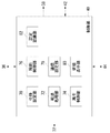
図8は、撮影画像出力システム10における表示システム12と撮像装置18の接続構成例を示す。図8(a)は最小単位の接続構成を示し、表示システム12と撮像装置18が1対1で接続される。この場合、互いに通信相手は一つに限られることから、図4の対象設定部94や図5の転送処理部72は、それぞれ特に送信先や送信元を選択する処理を必要としない。
【0041】
図8(b)は表示システム12と撮像装置18が1対nで接続された構成を示す。例えば学校の教室に1台の表示システム12を設置し、複数の撮像装置18を複数の生徒に割り当てた状態が想定される。図4の対象設定部94は複数の撮像装置18をそれらのIPアドレスやMACアドレスなど固有の情報を参照して認識し、複数の撮像装置18のうちいずれかを画像の送信元として手動または自動で選択する。撮影画像出力システム10の全体構成を表す情報として、あらかじめ所定の管理者が撮像装置18のユーザ氏名とIPアドレスまたはMACアドレスの対応テーブルを作成してもよい。この対応テーブルを所定のサーバ上に保管して対象設定部94が適宜取得してもよいし、対応テーブルを格納したメモリカードなどの記録媒体を配布して対象設定部94に読み込ませてもよい。
【0042】
図8(c)は表示システム12と撮像装置18がn対1で接続された構成を示す。例えば、複数の表示システム12が設置され、撮像装置18で連写したときに各画像を順次別々の表示システム12に表示させる構成や、複数の画像を解像度別に異なる表示システム12に表示させる構成が想定される。図5の転送処理部72は複数の表示システム12をそれらのIPアドレスやMACアドレスなど固有の情報を参照して認識し、複数の表示システム12のうちいずれかを画像の送信先として手動または自動で選択する。撮影画像出力システム10の全体構成は対応テーブルで管理し、その対応テーブルを転送処理部72が取得してもよい。
【0043】
図8(d)は表示システム12と撮像装置18がn対nで接続された構成を示す。この構成は図8(b)と図8(c)の組み合わせであり、例えば学校内の複数の教室にそれぞれ1台ずつ表示システム12を設置し、各教室からそれぞれ複数の生徒に割り当てられた複数の撮像装置18が接続されるような学校全体の構成が想定される。また例えば、複数の表示システム12を設置し、複数の撮像装置18から早い者勝ちで画像を送信させ、その送信順序に応じて別々の表示システム12に表示させるような構成も想定できる。複数の表示システム12と複数の撮像装置18で画像を送信または受信する相手を互いに手動または自動で選択できる。
【0044】
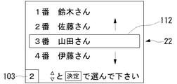
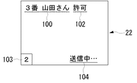
図9は、画像の送信元を選択する画面を例示する。本図は、表示装置14によりスクリーンに投影された投影画面22であり、複数の撮像装置18を示す装置番号とそれら装置のユーザ氏名がリストで表示されている。装置番号とユーザ氏名の対応テーブルは、あらかじめ撮影画像出力システム10の管理者が作成しておいてもよい。また、この表示システム12を示すシステム番号103が投影画面22の隅に表示される。表示システム12を操作するユーザは、カーソル112を上下に移動させて画像の送信を許可するユーザ氏名をリストから選択することができる。このようなユーザの指示に応じて図4の対象設定部94が画像の送信元を設定し、その送信元から受信する画像を表示装置14に出力するよう制御する。また、いずれの撮像装置18も選択せず、画像の表示をすべて拒否するよう設定してもよい。これらの選択に基づいて定まる表示可否の設定は許可条件として対象設定部94が記憶する。
【0045】
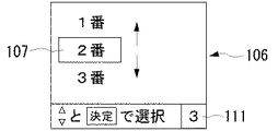
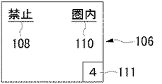
図10は、画像の送信先を選択する画面を例示する。本図は、撮像装置18の表示部38により表示された表示部画面106であり、複数の表示システム12を示すシステム番号がリストで表示されている。システム番号はあらかじめ管理者が複数の表示システム12に割り当てておいてもよい。また、この撮像装置18を示す装置番号111が表示部画面106の隅に表示される。撮像装置18を操作するユーザは、カーソル107を上下に移動させて画像の送信先、すなわち表示させたい表示システム12のシステム番号をリストから選択する。このようなユーザの指示に応じて図5の転送処理部72が画像の送信先を設定し、その送信先となる表示装置14へ画像を送信するよう制御する。
【0046】
第5の機能は、特定の許可条件の下で許可された画像だけを表示システム12に表示させ、それ以外の画像の表示を拒否する機能である。図4の対象設定部94は、許可条件に基づいて各画像の表示の可否を判断する。許可条件の内容として各画像に対してどのような規則で表示の可否を決定するかは種々定めることができる。例えば、表示システム12が一つの画像を受信して表示した後、一定の間は同じ撮像装置18からの送信であっても後続の画像の表示を拒否するよう許可条件を定めてもよい。図6に示すように、表示制御装置16が撮像装置18へ許可通知を送信した後(S14)、画像の受信を待機する受付モードを開始し(S17)、画像を受信して(S20)これを表示した後(S28)、受付モードを終了する(S30)。その後、同じ撮像装置18が新たな画像を撮影し(S32)、表示制御装置16へ画像の送信許可要求を送信しても(S34)、表示制御装置16は拒否通知を撮像装置18へ応答する(S36)。このとき、撮像装置18は撮影画像を表示部38で表示し(S38)、一方で表示制御装置16は受付モードを終了した状態であることを表示装置14に表示させる(S40)。
【0047】
他の許可条件として、例えば表示する画像を早い者勝ちで決定するよう許可条件を定めてもよい。すなわち、表示制御装置16が画像の受信を待機する受付モードに入ってから最初に送信された画像のみを表示する方式である。このとき、最初に送信された画像だけでなく、同じ撮像装置18から送信された画像の表示をその後も許可するよう許可条件を定めてもよい。
【0048】
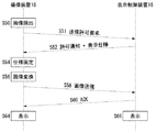
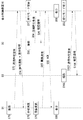
図11は、3台の撮像装置18から送信される画像を早い者勝ちで表示させる過程を示す。3台の撮像装置18をそれぞれカメラD1、カメラD2、カメラD3と表す。カメラD1が最初に画像を撮影し(S70)、画像の送信許可要求を表示制御装置16へ送信し(S72)、表示制御装置16は許可通知と表示画像の仕様を応答する(S74)。表示制御装置16はカメラD1のみを対象として受付モードを開始し(S77)、その前後にカメラD3が画像を撮影し(S92)、その後に送信許可要求を表示制御装置16へ送信しても(S94)、表示制御装置16は拒否通知を応答する(S96)。
【0049】
許可通知を受信したカメラD1は、画像の仕様を画定し(S76)、必要に応じて画像を変換し(S78)、仕様に適合する画像を表示制御装置16へ送信し(S80)、表示制御装置16はACK応答を送る(S82)。カメラD1と表示システム12はカメラD1による撮影画像をほぼ同時に表示し(S86、S88)、表示制御装置16は受付モードを終了する(S90)。その後、カメラD2が画像を撮影して(S100)、その撮影画像の送信許可要求を表示制御装置16へ送っても(S102)、表示制御装置16は拒否通知を応答する(S104)。
【0050】
他の許可条件として、例えば、図9で説明したように表示を許可する特定の撮像装置18を表示システム12を操作するユーザが手動で選択する形で許可条件を定めてもよい。
【0051】
第6の機能は、撮像装置18と表示制御装置16の間における通信の接続状況を表示する機能である。図12は、表示システム12が投影する投影画面22における表示内容を示す。投影画面22には接続状況104が表示される。図示する接続状況104は「送信中...」の文字であり、現在撮像装置18が表示装置14へ画像を送信している最中であることを示す。接続状況104として例えば「エラー」のように、通信の切断や画像の送信失敗を表示してもよい。例えば「受信104KB」のように、画像の受信に成功したことや受信した画像サイズを表示してもよい。
【0052】
図13は、撮像装置18の表示部画面106における表示内容を示す。表示部画面106にも接続状況110が表示される。図示する接続状況110は「圏内」の文字であり、現在撮像装置18が無線通信可能な圏内にいることが示される。無線通信が不可能な圏外にいるときは「圏外」の文字が接続状況110として表示部画面106に表示される。なお、図12に示す投影画面22の表示内容のように、「送信中...」「エラー」「受信104KB」といった文字を接続状況として表示部画面106に表示させてもよい。またこの表示内容を表示部画面106と投影画面22の双方に同時に表示させてもよい。これにより、ユーザは表示部画面106と投影画面22のどちらを見ても接続状況を確認できる。
【0053】
第7の機能は、撮像装置18に対する画像の表示可否を表示する機能である。
図12の投影画面22には、表示が許可されたユーザを示す許可対象者名100と許可表示102が表示される。複数の撮像装置18が一つの表示システム12に接続されるような構成の場合に、各撮像装置18のユーザは投影画面22における表示可否の表示を見て誰が許可されているのかを把握する。図13の表示部画面106には、表示可否108として「許可」または「禁止」の文字が表示され、その撮像装置18を操作するユーザは表示部画面106を見ることによっても表示の可否を把握できる。
【0054】
第8の機能は、撮像装置18と表示制御装置16の間で無線通信を確立するために必要な情報を自動設定する機能である。図4の通信設定部96は、撮像装置18が表示装置14と無線通信を確立するために必要な設定情報を保持する。設定情報は、例えば最低限必要な情報として表示装置14の固有なハードウェアアドレスであるMACアドレスであってもよいし、その他無線LANの設定に必要なESS−IDやWEPパスワード、IPアドレスなどの情報をさらに含んでもよい。設定画像生成部99は、これらの設定情報を視覚的に表現した設定画像を生成する。例えばMACアドレスを図形で表す2次元バーコードの画像を生成してもよいし、単にMACアドレスの文字列を表示した画像を生成してもよい。設定画像生成部99は、生成した設定画像を表示装置14へ出力して投影画面22に表示させる。撮像装置18は表示された設定画像を撮影し、その画像を図5の設定認識部82が読み取り、設定情報を認識する。設定画像に文字列が表示されている場合は、設定認識部82は文字認識により設定情報を認識する。通信設定部78はその設定情報を利用して表示装置14との通信を確立する。通信の確立方法は、MACアドレスを用いて最小限の情報交換が可能な通信を確保した上でさらに必要な設定情報を交換して画像送信が可能な通信を確立してもよい。
【0055】
この機能によれば、撮像装置18に手動で情報を入力することなく無線通信の設定を行うことができる。通常、撮像装置18には文字や数字を入力するなど本来の撮影とは無関係な情報入力インターフェイスは備わっていない。本機能を備えることによりそうしたユーザインターフェイスを新たに設ける必要がなく撮像装置18のインターフェイスを簡素にできる。
【0056】
図14は、撮像装置18と表示制御装置16をアクセスポイント28経由で接続する構成例を示す。図1では撮像装置18と表示制御装置16がアドホックモードで接続する例を示したが、本図ではインフラストラクチャモードで接続する例を示す。撮像装置18と表示制御装置16はそれぞれアクセスポイント28との間で無線通信を確立し、撮像装置18はアクセスポイント28を介して表示制御装置16へ画像を送信する。アクセスポイント28はネットワーク24を介して画像サーバ26と接続され、撮像装置18はアクセスポイント28とネットワーク24を経由して画像サーバ26に撮影画像を転送し、所定の領域に格納する。撮影画像を再生するときは適宜アクセスポイント28を介して画像サーバ26から受信する。
【0057】
本図のようなアクセスポイント28を介した無線通信は、撮像装置18と表示制御装置16を特に1対n、n対1、n対nで接続する場合に通信設定や通信制御が簡素となり好適である。また、撮像装置18で撮影した画像が画像サーバ26へ格納されるので、表示システム12が表示すべき画像を撮像装置18から送信するのではなく、表示制御装置16が画像サーバ26から逆に受信してもよい。さらに、画像を格納する領域は必ずしも画像サーバ26に限られず、撮像装置18や表示制御装置16に格納してもよく、その場合その画像がどの領域に格納されているかを示す情報を撮像装置18や表示制御装置16が保持する。これにより、ユーザは画像がどこに格納されているかを意識せずに画像を取り扱うことができる。
【0058】
以上、本発明を実施の形態をもとに説明した。この実施の形態は例示であり、その各構成要素や各処理プロセスの組合せにいろいろな変形例が可能なこと、またそうした変形例も本発明の範囲にあることは当業者に理解されるところである。
【0059】
なお、実施の形態における第6の機能により、表示システム12により投影した投影画面22と撮像装置18の表示部画面106にはそれぞれ接続状況を示す情報を表示する。この場合、投影画面22に表示させる接続状況と表示部画面106に表示させる接続状況は、異なる種類の情報であっても同じ種類の情報であってもいずれでもよい。変形例としては、接続状況の種類を投影画面22と表示部画面106で一致させるのみならず、両方に同じ画像を表示させることにより、画面内容をほぼすべて一致させるよう構成してもよい。これにより、ユーザは表示部画面106と投影画面22のいずれを見ても同じ内容を確認することができ、利便性が高い。
【0060】
【発明の効果】
本発明によれば、プロジェクタを利用してデジタルカメラ内の画像を表示させる上での利便性を高めることができる。
【図面の簡単な説明】
【図1】撮影画像出力システムの基本的な構成を示す図である。
【図2】表示制御装置の基本構成を示す機能ブロック図である。
【図3】撮像装置の基本構成を示す機能ブロック図である。
【図4】表示制御装置の制御部の詳細な構成を示す機能ブロック図である。
【図5】撮像装置の制御部の詳細な構成を示す機能ブロック図である。
【図6】撮影画像を撮像装置から表示制御装置へ送信する過程を示すフローチャートである。
【図7】撮影画像を撮像装置から表示制御装置へ送信する過程を示すフローチャートである。
【図8】撮影画像出力システムにおける表示システムと撮像装置の接続構成例を示す図である。
【図9】画像の送信元を選択する画面を例示する図である。
【図10】画像の送信先を選択する画面を例示する図である。
【図11】3台の撮像装置から送信される画像を早い者勝ちで表示させる過程を示すフローチャートである。
【図12】表示システムが投影する投影画面における表示内容を示す図である。
【図13】撮像装置の表示部画面における表示内容を示す図である。
【図14】撮像装置と表示制御装置をアクセスポイント経由で接続する構成例を示す図である。
【符号の説明】
10 撮影画像出力システム、 12 表示システム、 14 表示装置、 16 表示制御装置、 18 撮像装置、 20 無線通信、 38 表示部、
40 制御部、 54 制御部。[0001]
TECHNICAL FIELD OF THE INVENTION
The present invention relates to a display control method and a captured image output system that can use the method, a display control device, a liquid crystal projector, and a digital camera. The present invention particularly relates to a technique for transmitting a captured image via a wireless network.
[0002]
[Prior art]
2. Description of the Related Art A display device such as a liquid crystal projector for projecting an image on a screen has been conventionally used mainly for business and academic purposes for presentations and research presentations. However, in recent years, with the spread of DVDs, low-cost liquid crystal projectors have been developed one after another as products for home theater. Such a trend of cost reduction is facilitating introduction of a liquid crystal projector into a class in a school education setting.
[0003]
On the other hand, images shot by a digital camera are often used as contents projected by a liquid crystal projector. Recently, a technique has been proposed in which a digital camera is directly connected to a liquid crystal projector without using a personal computer to display an image (for example, see Patent Document 1).
[0004]
[Patent Document 1]
JP-A-11-317898 (full text)
[0005]
[Problems to be solved by the invention]
However, since the digital camera and the liquid crystal projector are directly connected according to the above-described prior art, the operator must be away from the liquid crystal projector during the operation of displaying the image in the digital camera with the liquid crystal projector or switching the image. Could not. Therefore, even if an attempt is made to shoot an image while the digital camera is connected to the liquid crystal projector, the shooting range is limited to the vicinity of the liquid crystal projector, which is inconvenient. In addition, since the position of the operator is limited to the vicinity of the liquid crystal projector, the operation becomes complicated when a plurality of operators want to perform alternate operations. Therefore, it was not always suitable for a method of utilizing such a technique that a plurality of students presented their images in a school education setting.
[0006]
The present invention has been made in view of such circumstances, and an object of the present invention is to enhance convenience in displaying an image in a digital camera using a projector. Another object of the present invention is to propose a new use method in a combination of a projector and a digital camera.
[0007]
[Means for Solving the Problems]
One embodiment of the present invention relates to a display control method. In this method, a specification of a captured image to be transmitted is defined between an imaging device and a display system based on a display capability, and a captured image conforming to the specification is transmitted from the imaging device to the display system via wireless communication. And a step of receiving and displaying the transmitted image by the display system. According to this aspect, an image suitable for the display capability of the display system is transmitted from the imaging device. Therefore, it is possible to easily display an optimum image without manually setting the image resolution and the file format.
[0008]
Another embodiment of the present invention relates to a captured image output system. The system includes an imaging device that captures an image of a subject and transmits the image via wireless communication, and a display system that receives the transmitted image via wireless communication and displays the image. Prior to transmission of the image, the specification of the image to be transmitted is defined between the display system and the imaging device based on the display capability of the display system. The specification may be defined immediately before transmitting the image, or the specification may be defined before capturing the image. For example, it may be determined when the power of the imaging apparatus is turned on. When the specification is defined before capturing an image, the imaging device may capture an image under conditions that are optimal for the specification. The display system may send the information on the display capability to the imaging device and select the specifications on the imaging device side to determine the specification, or the imaging device may send the information on the imaging capability to the display system and select it on the display system side. May be defined. Also in this mode, an image suitable for the display capability of the display system is transmitted from the imaging device. Therefore, it is possible to easily display an optimum image without manually setting the image resolution and the file format.
[0009]
Still another embodiment of the present invention relates to a display control method. The method includes the steps of: capturing an image of a subject; transmitting the captured image from the imaging device to an external display system via wireless communication in response to the capturing; and displaying the captured image on a display unit incorporated in the imaging device. And displaying at substantially the same time on the display system.
According to this aspect, the image captured by the imaging device is automatically transmitted to the display system without being manually instructed to transmit, and is immediately displayed. Therefore, the operator of the imaging device, that is, the photographer, can easily display the image in the imaging device on the display system without performing a troublesome operation. Further, a display system can be used as a substitute for the display unit incorporated in the imaging device, and the operability and the immediacy of reproduction are not impaired.
[0010]
Still another preferred embodiment according to the present invention relates to a captured image output system. The system includes an imaging device that captures an image of a subject and transmits the image via wireless communication, and a display system that receives the transmitted image via wireless communication and displays the image. Further, the photographed image is displayed almost simultaneously on the display unit and the display system incorporated in the imaging device, triggered by the photographing. Also in this mode, the captured image is automatically transmitted to the display system and immediately displayed. Therefore, the image in the imaging device can be easily displayed on the display system, and the operability and the immediacy of reproduction are not spoiled.
[0011]
Still another embodiment of the present invention relates to a display control method. The method includes the steps of: reading out an image instructed to be displayed on a display unit incorporated in the imaging device by the imaging device; and reading the read image from the imaging device to an external display system via wireless communication upon the reading. Transmitting, and causing the display unit and the display system to display the image instructed to be displayed substantially simultaneously. According to this aspect, the image to be reproduced on the display unit of the imaging device is immediately transmitted to the display system automatically and displayed without a manual transmission instruction. Therefore, the operator of the imaging device can easily display the image in the imaging device on the display system without performing a troublesome operation. Further, a display system can be used as a substitute for the display unit incorporated in the imaging device, and the operability and the immediacy of reproduction are not impaired.
[0012]
Still another preferred embodiment according to the present invention relates to a captured image output system. This system includes an imaging device that reads a captured image and transmits the image via wireless communication, and a display system that receives the transmitted image via wireless communication and displays the image.
In addition, the read image is displayed almost simultaneously on the display unit and the display system incorporated in the imaging device when the reading is performed. Also in this mode, the image to be reproduced on the display unit of the imaging device is automatically transmitted immediately to the display system and displayed. Therefore, the image in the imaging device can be easily displayed on the display system, and the operability and the immediacy of reproduction are not spoiled.
[0013]
Still another embodiment of the present invention relates to a display control method. The method includes the steps of recognizing a plurality of display systems capable of wireless communication, selecting one of a plurality of display systems as a transmission destination for transmitting a captured image via wireless communication, and triggering the captured image to capture the captured image. Transmitting to the selected display system via wireless communication. According to this aspect, one imaging device can be connected to a plurality of display systems, and a display destination can be selected from the plurality of display systems. A plurality of imaging devices can be connected to a plurality of display systems. Therefore, flexibility can be given to the combination of the display system and the imaging device, and the application can be expanded.
[0014]
Still another preferred embodiment according to the present invention relates to a captured image output system. The system includes an imaging device that captures an image of a subject and transmits the image via wireless communication, and a plurality of display systems that receive the image via wireless communication and display the image. In addition, the imaging device recognizes a plurality of display systems as transmission destinations of an image prior to transmission, selects one of the recognized plurality of display systems, and captures an image captured by the selected display system. Is transmitted via wireless communication. For example, the display destination may be selected according to the resolution of the captured image, or a separate display destination may be selected for each image during continuous shooting. Also in this aspect, one imaging device can be selectively displayed on a plurality of display systems, and the display system and the imaging device can be flexibly combined.
[0015]
Still another embodiment of the present invention relates to a display control method. The method includes the steps of: recognizing a plurality of imaging devices capable of wireless communication; selecting one of the plurality of imaging devices as a transmission source for transmitting a captured image via wireless communication; The method includes a step of capturing an image, and a step of transmitting the captured image to the display system via wireless communication upon the capturing of the captured image. According to this aspect, a plurality of imaging devices can be connected to one display system, and images can be transmitted and displayed from each imaging device to the display system alternately under a certain rule. A plurality of imaging devices can be connected to a plurality of display systems. Therefore, flexibility can be given to the combination of the display system and the imaging device, and the application can be expanded.
[0016]
Still another preferred embodiment according to the present invention relates to a captured image output system. This system includes a plurality of imaging devices that capture an image of a subject and transmit the image via wireless communication, and a display system that receives the image via wireless communication and displays the image. Further, the display system recognizes a plurality of imaging devices as image transmission sources prior to reception, selects one of the recognized plurality of imaging devices, and captures the captured image from the selected imaging device. Triggered by wireless communication. Also in this aspect, a plurality of imaging devices can be connected to one display system to display images alternately, and the display system and the imaging device can be flexibly combined.
[0017]
Still another embodiment of the present invention relates to a display control method. In this method, prior to transmitting and displaying a captured image from the imaging device to the display system via wireless communication and displaying the captured image, whether or not to display the captured image is determined based on a predetermined permission condition. Displaying the permitted captured image by the display system. The permission condition may determine whether display is possible for each captured image, or may determine whether display is possible for each imaging device. According to this aspect, the timing of displaying an image on the display system and the display target can be limited. Therefore, the display target sent from the imaging device can be restricted or managed by the display system.
[0018]
Still another preferred embodiment according to the present invention relates to a captured image output system. The system includes an imaging device that captures an image of a subject and transmits the image via wireless communication, and a display system that receives the transmitted image via wireless communication and displays the image. The display system determines whether or not to display the transmitted image based on a predetermined permission condition, and displays the transmitted image only when the display is permitted by the determination. The display availability may be determined automatically, or may be determined manually by the operator of the display system. Reception of an image may be permitted regardless of whether display is possible, or image reception may be denied unless display is permitted. Also in this embodiment, the display target on the display system can be controlled on the display system side.
[0019]
Still another embodiment of the present invention relates to a display control method. The method includes a step of detecting information on a connection state of wireless communication between the imaging device and the display system, and a step of displaying the information on the connection state by at least one of the imaging device and the display system. According to this aspect, an established state of wireless communication between the imaging apparatus and the display system, a state of image transmission, a state of wireless radio waves, and the like are displayed on either the display system or the imaging apparatus, or on both the display system and the imaging apparatus. Can be displayed. Therefore, the communication partner of the imaging device can be easily grasped regardless of the communication state. Further, a display system can be used as a substitute for the display unit built in the imaging device.
[0020]
Still another preferred embodiment according to the present invention relates to a captured image output system. The system includes an imaging device that captures an image of a subject and transmits the image via wireless communication, and a display system that receives the image via wireless communication and displays the image. In addition, at least one of the imaging device and the display system detects and displays information regarding the connection status of wireless communication between the imaging device and the display system. Also in this aspect, the state of communication performed between the imaging device and the display system can be displayed on either the display system or the imaging device, or on both the display system and the imaging device, and the communication state can be easily grasped.
[0021]
Still another embodiment of the present invention relates to a display control method. The method includes a step of determining whether or not a captured image transmitted from an imaging device to a display system via wireless communication can be displayed on the display system, and a step of displaying information on whether or not the display can be performed by the display system. The availability of display may be availability of display for a specific imaging device or availability of display at a specific timing. According to this aspect, the display restriction contents performed in the display system are displayed. Therefore, the display target permitted in the display system can be clarified, and the target can be easily grasped from the photographing device side.
[0022]
Still another preferred embodiment according to the present invention relates to a captured image output system. The system includes an imaging device that captures an image of a subject and transmits the image via wireless communication, and a display system that receives the image via wireless communication and displays the image. Further, the display system determines whether or not to display an image captured by the imaging device on the display system, and displays information regarding the determined display availability. Also in this mode, it is possible to easily grasp the display restriction contents in the display system.
[0023]
Still another embodiment of the present invention relates to a display control method. The method includes the steps of: generating a setting image visually representing setting information required to establish wireless communication between the imaging device and the display system; displaying the setting image; and displaying the setting image. Capturing an image of the subject as a subject, recognizing setting information based on the captured image, and establishing wireless communication between the imaging device and the display system based on the recognized setting information. . According to this aspect, by using the respective functions between the imaging device and the display system, communication is automatically established without performing a manual setting operation. Therefore, the imaging device and the display system can be easily connected without performing complicated setting work.
[0024]
Still another preferred embodiment according to the present invention relates to a captured image output system. The system includes an imaging device that captures an image of a subject and transmits the image via wireless communication, and a display system that receives the image via wireless communication and displays the image. In addition, the display system generates and displays a setting image that visually represents setting information necessary for establishing wireless communication with the imaging device. The imaging device captures an image with the displayed setting image as a subject, recognizes setting information based on the captured image, and establishes wireless communication with the display system based on the recognized setting information. Also in this mode, the imaging device and the display system can be automatically connected without performing complicated setting work.
[0025]
In addition, any combination of the above-described components and the components and expressions of the present invention, methods, devices, systems, computer programs, recording media storing the programs, and those which are mutually replaced among data structures, This is effective as an aspect of the present invention.
[0026]
BEST MODE FOR CARRYING OUT THE INVENTION
FIG. 1 shows a basic configuration of a captured
[0027]
The
[0028]
The configurations of the
[0029]
FIG. 2 is a functional block diagram illustrating a basic configuration of the
[0030]
FIG. 3 is a functional block diagram illustrating a basic configuration of the
The
[0031]
FIG. 4 is a functional block diagram illustrating a detailed configuration of the
[0032]
FIG. 5 is a functional block diagram illustrating a detailed configuration of the
[0033]
Hereinafter, functions of the captured
The first function is a function for defining specifications of an image to be displayed. The
[0034]
FIG. 6 is a flowchart illustrating a process of transmitting a captured image from the
[0035]
The second function is a function in which the
[0036]
6, after the image is transmitted from the
[0037]
The third function is a function of simultaneously displaying an image reproduced on the
[0038]
FIG. 7 is a flowchart illustrating a process of transmitting a captured image from the
[0039]
The fourth function is a function capable of connecting a plurality of
[0040]
FIG. 8 shows a connection configuration example of the
[0041]
FIG. 8B shows a configuration in which the
[0042]
FIG. 8C shows a configuration in which the
[0043]
FIG. 8D shows a configuration in which the
[0044]
FIG. 9 exemplifies a screen for selecting a transmission source of an image. This figure shows a
[0045]
FIG. 10 illustrates a screen for selecting a destination of an image. This figure is a
[0046]
The fifth function is a function of causing the
[0047]
As another permission condition, for example, a permission condition may be set so that an image to be displayed is determined on a first-come, first-served basis. That is, this is a method in which only the first transmitted image is displayed after the
[0048]
FIG. 11 shows a process of displaying images transmitted from the three
[0049]
Upon receiving the permission notification, the camera D1 determines the specifications of the image (S76), converts the image if necessary (S78), transmits an image conforming to the specifications to the display control device 16 (S80), and performs display control. The
[0050]
As another permission condition, for example, as described with reference to FIG. 9, the permission condition may be determined in such a manner that a user operating the
[0051]
The sixth function is a function of displaying a connection status of communication between the
[0052]
FIG. 13 shows display contents on the
[0053]
The seventh function is a function of displaying whether or not an image can be displayed on the
On the
[0054]
The eighth function is a function for automatically setting information necessary for establishing wireless communication between the
[0055]
According to this function, wireless communication settings can be performed without manually inputting information to the
[0056]
FIG. 14 shows a configuration example in which the
[0057]
The wireless communication via the
[0058]
The present invention has been described based on the embodiments. This embodiment is an exemplification, and it is understood by those skilled in the art that various modifications can be made to the combination of each component and each processing process, and that such modifications are also within the scope of the present invention. .
[0059]
By the sixth function in the embodiment, information indicating the connection status is displayed on the
[0060]
【The invention's effect】
ADVANTAGE OF THE INVENTION According to this invention, the convenience in displaying the image in a digital camera using a projector can be improved.
[Brief description of the drawings]
FIG. 1 is a diagram showing a basic configuration of a captured image output system.
FIG. 2 is a functional block diagram illustrating a basic configuration of a display control device.
FIG. 3 is a functional block diagram illustrating a basic configuration of the imaging apparatus.
FIG. 4 is a functional block diagram illustrating a detailed configuration of a control unit of the display control device.
FIG. 5 is a functional block diagram illustrating a detailed configuration of a control unit of the imaging device.
FIG. 6 is a flowchart illustrating a process of transmitting a captured image from an imaging device to a display control device.
FIG. 7 is a flowchart illustrating a process of transmitting a captured image from an imaging device to a display control device.
FIG. 8 is a diagram illustrating an example of a connection configuration between a display system and an imaging device in a captured image output system.
FIG. 9 is a diagram exemplifying a screen for selecting a transmission source of an image.
FIG. 10 is a diagram exemplifying a screen for selecting a transmission destination of an image.
FIG. 11 is a flowchart illustrating a process of displaying images transmitted from three imaging devices on a first-come, first-served basis.
FIG. 12 is a diagram showing display contents on a projection screen projected by the display system.
FIG. 13 is a diagram illustrating display contents on a display unit screen of the imaging apparatus.
FIG. 14 is a diagram illustrating a configuration example in which an imaging device and a display control device are connected via an access point.
[Explanation of symbols]
40 control part, 54 control part.
Claims (21)
前記仕様に適合した撮影画像を前記撮像装置から表示システムへ無線通信経由で送信するステップと、
前記送信された画像を前記表示システムで受信して表示するステップと、
を有することを特徴とする表示制御方法。Defining the specifications of the captured image to be transmitted based on the display capability between the imaging device and the display system;
Transmitting a captured image conforming to the specification from the imaging device to a display system via wireless communication,
Receiving and displaying the transmitted image on the display system;
A display control method, comprising:
前記送信された画像を無線通信経由で受信してその画像を表示する表示システムと、を備え、
前記画像の送信に先立ち、送信すべき画像の仕様を前記表示システムの表示能力に基づいて前記表示システムと撮像装置の間で画定することを特徴とする撮影画像出力システム。An imaging device that captures an image of a subject and transmits the image via wireless communication;
A display system that receives the transmitted image via wireless communication and displays the image,
A photographic image output system, wherein specifications of an image to be transmitted are defined between the display system and an imaging device based on a display capability of the display system before transmitting the image.
前記撮影した画像をその撮影を契機として撮像装置から外部の表示システムへ無線通信経由で送信するステップと、
前記撮影した画像を前記撮像装置が内蔵する表示部と前記表示システムでほぼ同時に表示させるステップと、を有することを特徴とする表示制御方法。Taking an image of the subject;
Transmitting the captured image from the imaging device to an external display system via wireless communication in response to the capturing,
Displaying the captured image substantially simultaneously on a display unit incorporated in the imaging device and the display system.
前記送信された画像を無線通信経由で受信してその画像を表示する表示システムと、を備え、
前記撮影した画像をその撮影を契機として前記撮像装置が内蔵する表示部と前記表示システムでほぼ同時に表示させることを特徴とする撮影画像出力システム。An imaging device that captures an image of a subject and transmits the image via wireless communication;
A display system that receives the transmitted image via wireless communication and displays the image,
A photographed image output system, wherein the photographed image is displayed almost simultaneously on a display unit incorporated in the imaging device and the display system when the photographed image is triggered.
前記読み出された画像をその読出を契機として前記撮像装置から外部の表示システムへ無線通信経由で送信するステップと、
前記表示が指示された画像を前記表示部と前記表示システムでほぼ同時に表示させるステップと、を有することを特徴とする表示制御方法。Reading the image instructed to be displayed on the display unit incorporated in the imaging device by the imaging device;
Transmitting the read image from the imaging device to an external display system via wireless communication in response to the reading,
Displaying the image instructed to be displayed substantially simultaneously on the display unit and the display system.
前記送信された画像を無線通信経由で受信してその画像を表示する表示システムと、を備え、
前記読み出された画像をその読出を契機として前記撮像装置が内蔵する表示部と前記表示システムでほぼ同時に表示させることを特徴とする撮影画像出力システム。An imaging device that reads a captured image and transmits the image via wireless communication,
A display system that receives the transmitted image via wireless communication and displays the image,
A photographed image output system, wherein the read image is displayed almost simultaneously on a display unit incorporated in the imaging device and the display system when the read image is read.
前記撮影画像をその撮影を契機として前記選択した表示システムへ無線通信経由で送信するステップと、を有することを特徴とする表示制御方法。Recognizing a plurality of display systems capable of wireless communication, and selecting one of the plurality of display systems as a transmission destination for transmitting a captured image via wireless communication,
Transmitting the photographed image to the selected display system via wireless communication in response to the photographing of the photographed image.
画像を無線通信経由で受信してその画像を表示する複数の表示システムと、を備え、
前記撮像装置は、前記送信に先立って画像の送信先として前記複数の表示システムを認識し、その認識した複数の表示システムからいずれかを選択し、選択した表示システムに対して前記撮影した画像をその撮影を契機として無線通信経由で送信することを特徴とする撮影画像出力システム。An imaging device that captures an image of a subject and transmits the image via wireless communication;
A plurality of display systems that receive the image via wireless communication and display the image,
The imaging apparatus recognizes the plurality of display systems as a destination of an image prior to the transmission, selects any one of the recognized plurality of display systems, and displays the captured image on the selected display system. A photographed image output system, wherein the photographed image is transmitted via wireless communication in response to the photographing.
撮影画像を無線通信経由で送信させる送信元として前記複数の撮像装置からいずれかを選択するステップと、
前記選択した撮像装置により被写体の画像を撮影するステップと、
前記撮影した画像をその撮影を契機として表示システムへ無線通信経由で送信するステップと、を有することを特徴とする表示制御方法。Recognizing a plurality of imaging devices capable of wireless communication;
Selecting any one of the plurality of imaging devices as a transmission source to transmit a captured image via wireless communication,
Taking an image of a subject with the selected imaging device;
Transmitting the captured image to a display system via wireless communication upon the capturing of the captured image.
画像を無線通信経由で受信してその画像を表示する表示システムと、を備え、前記表示システムは、前記受信に先立って画像の送信元として前記複数の撮像装置を認識し、その認識した複数の撮像装置からいずれかを選択し、選択した撮像装置から前記撮影された画像をその撮影を契機として無線通信経由で受信することを特徴とする撮影画像出力システム。A plurality of imaging devices for capturing an image of a subject and transmitting the image via wireless communication;
A display system that receives the image via wireless communication and displays the image, the display system recognizes the plurality of imaging devices as a source of the image prior to the reception, and recognizes the plurality of recognized images. A photographed image output system, wherein one of the photographed devices is selected, and the photographed image is received from the selected photographed device via wireless communication when the photographed image is triggered.
前記決定により表示が許可された撮影画像を前記表示システムにより表示するステップと、を有することを特徴とする表示制御方法。Prior to transmitting and displaying a captured image from the imaging device to the display system via wireless communication and displaying the captured image, determining whether to display the captured image based on predetermined permission conditions,
Displaying the captured image permitted to be displayed by the determination by the display system.
前記送信された画像を無線通信経由で受信してその画像を表示する表示システムと、を備え、
前記表示システムは、前記送信される画像に関して表示の可否を所定の許可条件に基づいて決定するとともに、前記決定によって表示を許可した場合に限り前記送信される画像を表示することを特徴とする撮影画像出力システム。An imaging device that captures an image of a subject and transmits the image via wireless communication;
A display system that receives the transmitted image via wireless communication and displays the image,
The display system determines whether or not to display the transmitted image based on a predetermined permission condition, and displays the transmitted image only when the display is permitted by the determination. Image output system.
前記接続状況に関する情報を前記撮像装置および表示システムのうち少なくともいずれかにより表示するステップと、を有することを特徴とする表示制御方法。Detecting information about the connection status of wireless communication between the imaging device and the display system;
Displaying information on the connection status by at least one of the imaging device and the display system.
画像を無線通信経由で受信してその画像を表示する表示システムと、を備え、前記撮像装置および表示システムのうち少なくともいずれかが、前記撮像装置と表示システムの間における無線通信の接続状況に関する情報を検出して表示することを特徴とする撮影画像出力システム。An imaging device that captures an image of a subject and transmits the image via wireless communication;
A display system that receives an image via wireless communication and displays the image, wherein at least one of the imaging device and the display system is connected to a wireless communication connection state between the imaging device and the display system. A captured image output system for detecting and displaying an image.
前記表示の可否に関する情報を前記表示システムにより表示するステップと、
を有することを特徴とする表示制御方法。Determining whether or not the captured image transmitted from the imaging device to the display system via wireless communication can be displayed on the display system,
Displaying information on whether or not the display is possible by the display system;
A display control method, comprising:
画像を無線通信経由で受信してその画像を表示する表示システムと、を備え、前記表示システムは、前記撮像装置で撮影された画像の前記表示システムにおける表示の可否を決定し、決定された表示の可否に関する情報を表示することを特徴とする撮影画像出力システム。An imaging device that captures an image of a subject and transmits the image via wireless communication;
A display system that receives an image via wireless communication and displays the image, the display system determines whether or not an image captured by the imaging device can be displayed on the display system, and the determined display A photographed image output system for displaying information on whether or not the photographing is possible.
前記設定画像を表示するステップと、
前記表示された設定画像を被写体とした画像を撮影するステップと、
前記撮影した画像に基づいて前記設定情報を認識するステップと、
前記認識した設定情報に基づいて前記撮像装置と表示システムの間で無線通信を確立するステップと、を有することを特徴とする表示制御方法。Generating a setting image that visually represents the setting information required to establish wireless communication between the imaging device and the display system,
Displaying the setting image;
Shooting an image with the displayed setting image as a subject,
Recognizing the setting information based on the captured image;
Establishing a wireless communication between the imaging device and a display system based on the recognized setting information.
画像を無線通信経由で受信してその画像を表示する表示システムと、を備え、前記表示システムは、前記撮像装置との無線通信の確立に必要な設定情報を視覚的に表現した設定画像を生成してこれを表示し、
前記撮像装置は、前記表示された設定画像を被写体とした画像を撮影し、撮影した画像に基づいて前記設定情報を認識し、認識した設定情報に基づいて前記表示システムとの無線通信を確立することを特徴とする撮影画像出力システム。An imaging device that captures an image of a subject and transmits the image via wireless communication;
A display system that receives an image via wireless communication and displays the image, wherein the display system generates a setting image that visually represents setting information necessary for establishing wireless communication with the imaging device. To show this,
The imaging device captures an image of the displayed setting image as a subject, recognizes the setting information based on the captured image, and establishes wireless communication with the display system based on the recognized setting information. A photographed image output system, characterized in that:
Priority Applications (8)
| Application Number | Priority Date | Filing Date | Title |
|---|---|---|---|
| JP2003006453A JP2004221908A (en) | 2003-01-14 | 2003-01-14 | Method for controlling display, photographed image output sysetm capable of using the method, display control device, liquid crystal projector, and digital camera |
| GB0330108A GB2397717B (en) | 2003-01-14 | 2003-12-29 | Captured image outputting system, and display control method. |
| GB0509839A GB2412265B (en) | 2003-01-14 | 2003-12-29 | Captured image outputting system, display control apparatus, liquid crystal projector and digital camera that transmit images via wireless network |
| CN201010165652A CN101820493A (en) | 2003-01-14 | 2004-01-06 | Captured image outputting system, display control unit, liquid crystal projection apparatus and digital camera |
| CN2004100012965A CN1517778B (en) | 2003-01-14 | 2004-01-06 | Photographed image output system, display control device, liquid crystal projector, and digital camera |
| US10/751,897 US7463216B2 (en) | 2003-01-14 | 2004-01-07 | Captured image outputting system, display control apparatus, liquid crystal projector and digital camera that transmit images via wireless network |
| US11/980,404 US20080136918A1 (en) | 2003-01-14 | 2007-10-31 | Captured image outputting system, display control apparatus, liquid crystal projector and digital camera that transmit images via wireless network |
| US13/116,719 US20110227811A1 (en) | 2003-01-14 | 2011-05-26 | Captured image outputting system, display control apparatus, liquid crystal projector and digital camera that transmit images via wireless network |
Applications Claiming Priority (1)
| Application Number | Priority Date | Filing Date | Title |
|---|---|---|---|
| JP2003006453A JP2004221908A (en) | 2003-01-14 | 2003-01-14 | Method for controlling display, photographed image output sysetm capable of using the method, display control device, liquid crystal projector, and digital camera |
Related Child Applications (1)
| Application Number | Title | Priority Date | Filing Date |
|---|---|---|---|
| JP2007045417A Division JP2007184967A (en) | 2007-02-26 | 2007-02-26 | Digital camera |
Publications (1)
| Publication Number | Publication Date |
|---|---|
| JP2004221908A true JP2004221908A (en) | 2004-08-05 |
Family
ID=31712389
Family Applications (1)
| Application Number | Title | Priority Date | Filing Date |
|---|---|---|---|
| JP2003006453A Pending JP2004221908A (en) | 2003-01-14 | 2003-01-14 | Method for controlling display, photographed image output sysetm capable of using the method, display control device, liquid crystal projector, and digital camera |
Country Status (4)
| Country | Link |
|---|---|
| US (3) | US7463216B2 (en) |
| JP (1) | JP2004221908A (en) |
| CN (2) | CN1517778B (en) |
| GB (1) | GB2397717B (en) |
Cited By (16)
| Publication number | Priority date | Publication date | Assignee | Title |
|---|---|---|---|---|
| JP2005026853A (en) * | 2003-06-30 | 2005-01-27 | Toshiba Corp | Wireless connection switching system for display information |
| JP2006253854A (en) * | 2005-03-09 | 2006-09-21 | Sanyo Electric Co Ltd | Data transfer device |
| JP2006339781A (en) * | 2005-05-31 | 2006-12-14 | Sharp Corp | Relay device and communication system |
| KR100680748B1 (en) | 2004-11-03 | 2007-02-08 | 삼성전자주식회사 | Wireless projector system |
| JP2007158406A (en) * | 2005-11-30 | 2007-06-21 | Nikon Corp | TV set |
| JP2007158408A (en) * | 2005-11-30 | 2007-06-21 | Nikon Corp | TV set |
| WO2010001941A1 (en) * | 2008-06-30 | 2010-01-07 | Canon Kabushiki Kaisha | Display apparatus, control method for display apparatus, and computer program |
| JP2010072352A (en) * | 2008-09-18 | 2010-04-02 | Sanyo Electric Co Ltd | Image display system, transmitter and receiver |
| JP2010140387A (en) * | 2008-12-15 | 2010-06-24 | Panasonic Corp | Image display system, image display device and network connection method |
| KR101025036B1 (en) | 2009-06-02 | 2011-03-25 | 주식회사 케이티 | Projector linked with M2M module and its driving method |
| JP2011109453A (en) * | 2009-11-18 | 2011-06-02 | Olympus Imaging Corp | Imaging apparatus system, external apparatus, and adapter |
| JP2011172097A (en) * | 2010-02-19 | 2011-09-01 | Nippon Telegr & Teleph Corp <Ntt> | Remote control system, remote control method, and program |
| US8279258B2 (en) | 2006-09-21 | 2012-10-02 | Seiko Epson Corporation | Image display device, image display system, and network connection method |
| US8384660B2 (en) | 2007-07-13 | 2013-02-26 | Seiko Epson Corporation | Display system, display device and display method |
| WO2013051539A1 (en) * | 2011-10-05 | 2013-04-11 | 三洋電機株式会社 | Electronic camera |
| US11153472B2 (en) | 2005-10-17 | 2021-10-19 | Cutting Edge Vision, LLC | Automatic upload of pictures from a camera |
Families Citing this family (43)
| Publication number | Priority date | Publication date | Assignee | Title |
|---|---|---|---|---|
| JP2004221908A (en) * | 2003-01-14 | 2004-08-05 | Sanyo Electric Co Ltd | Method for controlling display, photographed image output sysetm capable of using the method, display control device, liquid crystal projector, and digital camera |
| JP4416550B2 (en) * | 2004-03-29 | 2010-02-17 | 富士フイルム株式会社 | Digital still camera and control method thereof |
| JP4971594B2 (en) * | 2004-03-31 | 2012-07-11 | キヤノン株式会社 | Program and display control device |
| JP2006086654A (en) * | 2004-09-14 | 2006-03-30 | Canon Inc | Imaging device |
| KR20060026228A (en) * | 2004-09-20 | 2006-03-23 | 삼성테크윈 주식회사 | Digital camera using touch screen display panel as remote controller and its driving method |
| US20060088064A1 (en) * | 2004-10-25 | 2006-04-27 | Dampier Trevis J Sr | Trejon interlink system |
| JP4040619B2 (en) * | 2004-11-08 | 2008-01-30 | キヤノン株式会社 | Image output apparatus, control method therefor, and image output system |
| US9489717B2 (en) * | 2005-01-31 | 2016-11-08 | Invention Science Fund I, Llc | Shared image device |
| US8902320B2 (en) | 2005-01-31 | 2014-12-02 | The Invention Science Fund I, Llc | Shared image device synchronization or designation |
| US8606383B2 (en) | 2005-01-31 | 2013-12-10 | The Invention Science Fund I, Llc | Audio sharing |
| US9082456B2 (en) | 2005-01-31 | 2015-07-14 | The Invention Science Fund I Llc | Shared image device designation |
| US9124729B2 (en) | 2005-01-31 | 2015-09-01 | The Invention Science Fund I, Llc | Shared image device synchronization or designation |
| US20060174203A1 (en) | 2005-01-31 | 2006-08-03 | Searete Llc, A Limited Liability Corporation Of The State Of Delaware | Viewfinder for shared image device |
| US9910341B2 (en) | 2005-01-31 | 2018-03-06 | The Invention Science Fund I, Llc | Shared image device designation |
| KR100618272B1 (en) * | 2005-02-17 | 2006-09-11 | 엘지전자 주식회사 | Wireless Television System With Memory Reader Part And Image Display Method thereof |
| US9819490B2 (en) | 2005-05-04 | 2017-11-14 | Invention Science Fund I, Llc | Regional proximity for shared image device(s) |
| US9001215B2 (en) | 2005-06-02 | 2015-04-07 | The Invention Science Fund I, Llc | Estimating shared image device operational capabilities or resources |
| US10003762B2 (en) | 2005-04-26 | 2018-06-19 | Invention Science Fund I, Llc | Shared image devices |
| JP2007019745A (en) * | 2005-07-06 | 2007-01-25 | Nikon Corp | Image processing system |
| JP4797674B2 (en) * | 2006-02-13 | 2011-10-19 | ソニー株式会社 | Information processing apparatus and method, and program |
| ES2721823T5 (en) | 2007-04-24 | 2022-03-25 | Signify Holding Bv | Method, system and user interface for automatically creating an atmosphere, in particular a lighting atmosphere, based on a keyword input |
| KR101362763B1 (en) * | 2007-05-31 | 2014-02-14 | 삼성전자주식회사 | Method for transferring content between apparatuses and content transmission apparatus |
| JP4462331B2 (en) | 2007-11-05 | 2010-05-12 | ソニー株式会社 | Imaging apparatus, control method, program |
| US8130275B2 (en) | 2008-06-13 | 2012-03-06 | Nintendo Co., Ltd. | Information-processing apparatus, and storage medium storing a photographing application launch program executed by information-processing apparatus |
| JP4181211B1 (en) | 2008-06-13 | 2008-11-12 | 任天堂株式会社 | Information processing apparatus and startup program executed therein |
| US8848100B2 (en) * | 2008-10-01 | 2014-09-30 | Nintendo Co., Ltd. | Information processing device, information processing system, and launch program and storage medium storing the same providing photographing functionality |
| KR101619090B1 (en) * | 2009-11-13 | 2016-05-19 | 삼성전자주식회사 | System and method for remote reproducing contents |
| JP5421762B2 (en) * | 2009-12-22 | 2014-02-19 | キヤノン株式会社 | Display device, control method thereof, and display system |
| JP2011155434A (en) * | 2010-01-27 | 2011-08-11 | Elmo Co Ltd | Material presentation system |
| JP2011155435A (en) * | 2010-01-27 | 2011-08-11 | Elmo Co Ltd | Material presentation device |
| US9110495B2 (en) * | 2010-02-03 | 2015-08-18 | Microsoft Technology Licensing, Llc | Combined surface user interface |
| JP5620851B2 (en) * | 2010-08-17 | 2014-11-05 | パナソニック株式会社 | Electronic device, electronic device system, and image processing method |
| JP5811602B2 (en) * | 2010-12-16 | 2015-11-11 | ソニー株式会社 | Image generation apparatus, program, image display system, and image display apparatus |
| JP5870733B2 (en) | 2012-02-14 | 2016-03-01 | セイコーエプソン株式会社 | Display device and control method of display device |
| JP5994275B2 (en) * | 2012-02-14 | 2016-09-21 | セイコーエプソン株式会社 | Display device and control method of display device |
| US9826572B2 (en) | 2012-03-15 | 2017-11-21 | Intel Corporation | Wireless enhanced projector |
| KR102105168B1 (en) * | 2013-05-15 | 2020-04-24 | 삼성전자주식회사 | Display apparatus and control method of the same |
| CN103634565A (en) * | 2013-09-24 | 2014-03-12 | 北京环境特性研究所 | OMAP-based ultraviolet and visible light dual-channel image acquisition, processing and display system |
| US9679194B2 (en) * | 2014-07-17 | 2017-06-13 | At&T Intellectual Property I, L.P. | Automated obscurity for pervasive imaging |
| CN104994319B (en) * | 2015-06-12 | 2018-11-09 | 联想(北京)有限公司 | A kind of information processing method and electronic equipment |
| CN105976765B (en) * | 2016-05-11 | 2018-06-15 | 深圳市国华光电科技有限公司 | A kind of display system and display control method |
| CN106507025A (en) * | 2016-11-17 | 2017-03-15 | 宁波菊风系统软件有限公司 | A kind of mobile terminal and panoramic video communication method |
| JP7463960B2 (en) * | 2018-05-29 | 2024-04-09 | ソニーグループ株式会社 | Projector, control method thereof, and image system |
Family Cites Families (49)
| Publication number | Priority date | Publication date | Assignee | Title |
|---|---|---|---|---|
| JP3112411B2 (en) * | 1996-01-11 | 2000-11-27 | 松下電器産業株式会社 | Video transmission equipment |
| US5963245A (en) * | 1997-09-24 | 1999-10-05 | Mcdonald; Arcaster | Video telephone |
| US6771896B2 (en) * | 1997-10-03 | 2004-08-03 | Konica Corporation | Electric camera with image printing system |
| US6535243B1 (en) * | 1998-01-06 | 2003-03-18 | Hewlett- Packard Company | Wireless hand-held digital camera |
| JPH11284986A (en) | 1998-03-30 | 1999-10-15 | Victor Co Of Japan Ltd | Image transmitter |
| US6385772B1 (en) * | 1998-04-30 | 2002-05-07 | Texas Instruments Incorporated | Monitoring system having wireless remote viewing and control |
| US6775361B1 (en) * | 1998-05-01 | 2004-08-10 | Canon Kabushiki Kaisha | Recording/playback apparatus with telephone and its control method, video camera with telephone and its control method, image communication apparatus, and storage medium |
| JPH11317898A (en) | 1998-05-07 | 1999-11-16 | Minolta Co Ltd | Digital camera |
| US6335753B1 (en) * | 1998-06-15 | 2002-01-01 | Mcdonald Arcaster | Wireless communication video telephone |
| US20020170064A1 (en) * | 2001-05-11 | 2002-11-14 | Monroe David A. | Portable, wireless monitoring and control station for use in connection with a multi-media surveillance system having enhanced notification functions |
| JP2000181588A (en) | 1998-12-14 | 2000-06-30 | Nec Corp | Device with infrared communication module |
| EP1032201B1 (en) * | 1999-02-26 | 2005-11-02 | Canon Kabushiki Kaisha | Image display control system and method |
| DE60043259D1 (en) * | 1999-03-17 | 2009-12-17 | Komatsu Mfg Co Ltd | COMMUNICATION ARRANGEMENT OF A MOBILE UNIT |
| US6346950B1 (en) * | 1999-05-20 | 2002-02-12 | Compaq Computer Corporation | System and method for display images using anamorphic video |
| JP2001036893A (en) * | 1999-07-19 | 2001-02-09 | Matsushita Electric Ind Co Ltd | Monitoring device |
| JP2001083948A (en) | 1999-09-13 | 2001-03-30 | Canon Inc | Display device and method thereof |
| US7403510B1 (en) * | 1999-11-10 | 2008-07-22 | Fujifilm Corporation | Communication terminal apparatus, communication method thereof, and connected destination selection method in wireless LAN |
| US6538686B2 (en) * | 2000-01-07 | 2003-03-25 | Minolta Co., Ltd. | Method for transmitting image data and communication terminal |
| JP3738383B2 (en) * | 2000-05-26 | 2006-01-25 | 富士通株式会社 | Communication device |
| US7796162B2 (en) * | 2000-10-26 | 2010-09-14 | Front Row Technologies, Llc | Providing multiple synchronized camera views for broadcast from a live venue activity to remote viewers |
| JP3925051B2 (en) * | 2000-07-17 | 2007-06-06 | カシオ計算機株式会社 | Digital camera, image display device and image transmission / reception system |
| JP3820085B2 (en) * | 2000-07-31 | 2006-09-13 | オリンパス株式会社 | Electronic camera |
| CN1337826A (en) * | 2000-08-04 | 2002-02-27 | 丁小明 | Method and system for radio narrowband transmission and real-time internet release of moving image |
| JP4445653B2 (en) | 2000-08-08 | 2010-04-07 | オリンパス株式会社 | Electronic camera |
| JP2002094735A (en) * | 2000-09-14 | 2002-03-29 | Fujitsu Ltd | Image data conversion system and image data transfer device |
| CN1227890C (en) | 2000-09-18 | 2005-11-16 | 皇家菲利浦电子有限公司 | Standalone monitor used as a digital photo display projector |
| GB2370188A (en) * | 2000-11-01 | 2002-06-19 | Orange Personal Comm Serv Ltd | Mixed-media telecommunication call set-up |
| CA2444090C (en) * | 2001-04-19 | 2011-06-14 | Masaki Sugimura | Apparatus and method for connecting apparatuses using radio link, method for creating usable scene table for apparatus connection, and recording medium |
| US7433710B2 (en) * | 2001-04-20 | 2008-10-07 | Lightsurf Technologies, Inc. | System and methodology for automated provisioning of new user accounts |
| JP2002320115A (en) * | 2001-04-24 | 2002-10-31 | Olympus Optical Co Ltd | Digital camera and digital imaging system |
| US7100190B2 (en) * | 2001-06-05 | 2006-08-29 | Honda Giken Kogyo Kabushiki Kaisha | Automobile web cam and communications system incorporating a network of automobile web cams |
| JP2002366565A (en) | 2001-06-06 | 2002-12-20 | Olympus Optical Co Ltd | Image storage system |
| US7154535B2 (en) * | 2001-07-13 | 2006-12-26 | Matsushita Electric Industrial Co., Ltd. | Digital camera capable of directly accessing images recorded on another digital camera |
| GB0118436D0 (en) * | 2001-07-27 | 2001-09-19 | Hewlett Packard Co | Synchronised cameras with auto-exchange |
| JP4076057B2 (en) * | 2001-09-26 | 2008-04-16 | 富士フイルム株式会社 | Image data transmission method, digital camera, and program |
| JP4174208B2 (en) * | 2001-12-03 | 2008-10-29 | ソニー株式会社 | Information processing terminal and information processing method |
| US6833843B2 (en) * | 2001-12-03 | 2004-12-21 | Tempest Microsystems | Panoramic imaging and display system with canonical magnifier |
| US6830340B2 (en) * | 2001-12-26 | 2004-12-14 | Infocus Corporation | Image-rendering device |
| WO2003085567A2 (en) * | 2002-04-11 | 2003-10-16 | Accenture Global Services Gmbh | On demand real-time knowledge based connectivity |
| JP2003333673A (en) * | 2002-05-13 | 2003-11-21 | Nec Corp | Portable communication terminal, remote control method and remote control system |
| US20040066456A1 (en) * | 2002-06-21 | 2004-04-08 | David Read | Visual imaging network systems and methods |
| US20040012810A1 (en) * | 2002-07-19 | 2004-01-22 | Haas William Robert | System and method for presenting images captured at an event during the event |
| US6996394B2 (en) * | 2002-08-30 | 2006-02-07 | Qualcomm Incorporated | Server processing in providing messages for a wireless device connecting to a server |
| US20040111324A1 (en) * | 2002-12-06 | 2004-06-10 | Kim Jeong T. | Integrated point-of-sale and surveillance system |
| US20040123328A1 (en) * | 2002-12-20 | 2004-06-24 | Ecamsecure, Inc. | Mobile surveillance vehicle |
| JP2004221908A (en) * | 2003-01-14 | 2004-08-05 | Sanyo Electric Co Ltd | Method for controlling display, photographed image output sysetm capable of using the method, display control device, liquid crystal projector, and digital camera |
| WO2005094270A2 (en) * | 2004-03-24 | 2005-10-13 | Sharp Laboratories Of America, Inc. | Methods and systems for a/v input device to diplay networking |
| US7962854B2 (en) * | 2004-10-19 | 2011-06-14 | Sony Ericsson Mobile Communications Ab | Systems, methods and computer program products for displaying content on multiple display screens using handheld wireless communicators |
| US8582973B2 (en) * | 2005-09-13 | 2013-11-12 | Nikon Corporation | Data communication apparatus, electronic camera, and data communication system |
-
2003
- 2003-01-14 JP JP2003006453A patent/JP2004221908A/en active Pending
- 2003-12-29 GB GB0330108A patent/GB2397717B/en not_active Expired - Fee Related
-
2004
- 2004-01-06 CN CN2004100012965A patent/CN1517778B/en not_active Expired - Fee Related
- 2004-01-06 CN CN201010165652A patent/CN101820493A/en active Pending
- 2004-01-07 US US10/751,897 patent/US7463216B2/en not_active Expired - Lifetime
-
2007
- 2007-10-31 US US11/980,404 patent/US20080136918A1/en not_active Abandoned
-
2011
- 2011-05-26 US US13/116,719 patent/US20110227811A1/en not_active Abandoned
Cited By (24)
| Publication number | Priority date | Publication date | Assignee | Title |
|---|---|---|---|---|
| JP2005026853A (en) * | 2003-06-30 | 2005-01-27 | Toshiba Corp | Wireless connection switching system for display information |
| KR100680748B1 (en) | 2004-11-03 | 2007-02-08 | 삼성전자주식회사 | Wireless projector system |
| JP2006253854A (en) * | 2005-03-09 | 2006-09-21 | Sanyo Electric Co Ltd | Data transfer device |
| JP2006339781A (en) * | 2005-05-31 | 2006-12-14 | Sharp Corp | Relay device and communication system |
| US11818458B2 (en) | 2005-10-17 | 2023-11-14 | Cutting Edge Vision, LLC | Camera touchpad |
| US11153472B2 (en) | 2005-10-17 | 2021-10-19 | Cutting Edge Vision, LLC | Automatic upload of pictures from a camera |
| JP2007158408A (en) * | 2005-11-30 | 2007-06-21 | Nikon Corp | TV set |
| JP2007158406A (en) * | 2005-11-30 | 2007-06-21 | Nikon Corp | TV set |
| US8279258B2 (en) | 2006-09-21 | 2012-10-02 | Seiko Epson Corporation | Image display device, image display system, and network connection method |
| US9432644B2 (en) | 2006-09-21 | 2016-08-30 | Seiko Epson Corporation | Image display device, image display system, and network connection method |
| US8933984B2 (en) | 2006-09-21 | 2015-01-13 | Seiko Epson Corporation | Image display device, image display system, and network connection method |
| US8760399B2 (en) | 2007-07-13 | 2014-06-24 | Seiko Epson Corporation | Display system, display device and display method |
| US8384660B2 (en) | 2007-07-13 | 2013-02-26 | Seiko Epson Corporation | Display system, display device and display method |
| US8780274B2 (en) | 2008-06-30 | 2014-07-15 | Canon Kabushiki Kaisha | Display apparatus, control method for display apparatus, and computer program |
| US9137460B2 (en) | 2008-06-30 | 2015-09-15 | Canon Kabushiki Kaisha | Display apparatus, control method for display apparatus, and computer program |
| JP2010008937A (en) * | 2008-06-30 | 2010-01-14 | Canon Inc | Display, control method of display, and computer program |
| WO2010001941A1 (en) * | 2008-06-30 | 2010-01-07 | Canon Kabushiki Kaisha | Display apparatus, control method for display apparatus, and computer program |
| JP2010072352A (en) * | 2008-09-18 | 2010-04-02 | Sanyo Electric Co Ltd | Image display system, transmitter and receiver |
| JP2010140387A (en) * | 2008-12-15 | 2010-06-24 | Panasonic Corp | Image display system, image display device and network connection method |
| KR101025036B1 (en) | 2009-06-02 | 2011-03-25 | 주식회사 케이티 | Projector linked with M2M module and its driving method |
| JP2011109453A (en) * | 2009-11-18 | 2011-06-02 | Olympus Imaging Corp | Imaging apparatus system, external apparatus, and adapter |
| JP2011172097A (en) * | 2010-02-19 | 2011-09-01 | Nippon Telegr & Teleph Corp <Ntt> | Remote control system, remote control method, and program |
| WO2013051539A1 (en) * | 2011-10-05 | 2013-04-11 | 三洋電機株式会社 | Electronic camera |
| JP2013093823A (en) * | 2011-10-05 | 2013-05-16 | Sanyo Electric Co Ltd | Electronic camera |
Also Published As
| Publication number | Publication date |
|---|---|
| US7463216B2 (en) | 2008-12-09 |
| US20110227811A1 (en) | 2011-09-22 |
| US20080136918A1 (en) | 2008-06-12 |
| CN101820493A (en) | 2010-09-01 |
| CN1517778A (en) | 2004-08-04 |
| GB2397717B (en) | 2005-10-26 |
| GB0330108D0 (en) | 2004-02-04 |
| GB2397717A (en) | 2004-07-28 |
| US20040140971A1 (en) | 2004-07-22 |
| CN1517778B (en) | 2010-07-14 |
Similar Documents
| Publication | Publication Date | Title |
|---|---|---|
| CN1517778B (en) | Photographed image output system, display control device, liquid crystal projector, and digital camera | |
| JP4629929B2 (en) | Digital camera system and control method thereof | |
| JP4786664B2 (en) | DATA TRANSMITTING DEVICE AND ITS CONTROL METHOD, DATA TRANSMITTING DEVICE CONTROL PROGRAM, AND RECORDING MEDIUM CONTAINING THE PROGRAM | |
| JP5994313B2 (en) | Information providing apparatus, transmission system, and program | |
| US7062230B1 (en) | Communication device, image-pickup device, storage medium and communication method | |
| US9377848B2 (en) | Image processing apparatus, control method thereof, and recording medium for performing data transmission | |
| US9871989B2 (en) | Communication apparatus and method of controlling communication apparatus | |
| JP2007215070A (en) | Information processing apparatus and method, and program | |
| JP3996495B2 (en) | Digital camera and control method thereof | |
| JP4618356B2 (en) | Electronic device and program | |
| JP4208133B2 (en) | Imaging control method, apparatus, and program | |
| JP2007184967A (en) | Digital camera | |
| JP4274416B2 (en) | Imaging apparatus control method, apparatus, and program | |
| JP2004140799A (en) | Imaging apparatus control method, apparatus, and program | |
| JP6882012B2 (en) | Communication device, control method of communication device, and program | |
| GB2412265A (en) | Capturing image of displayed settings information to control communication | |
| JP2006235159A (en) | Image display device and program for operating the same | |
| JP2005094570A (en) | Photographed image display method and display processing apparatus using the method | |
| JP2004140795A (en) | Imaging apparatus control method, apparatus, and program | |
| CN107025079B (en) | System and method for document reproduction | |
| JP2004140796A (en) | Imaging apparatus control method, apparatus, and program | |
| US11178343B2 (en) | Combining images from different devices according to a determined wipe shape | |
| JP2001016344A (en) | Data communication device and system and method thereof | |
| JP2004120607A (en) | Camera control method, apparatus, and program | |
| JP2023137937A (en) | Electronic apparatus with communication function, and control method and program thereof |
Legal Events
| Date | Code | Title | Description |
|---|---|---|---|
| A621 | Written request for application examination |
Free format text: JAPANESE INTERMEDIATE CODE: A621 Effective date: 20041201 |
|
| A977 | Report on retrieval |
Free format text: JAPANESE INTERMEDIATE CODE: A971007 Effective date: 20060920 |
|
| A131 | Notification of reasons for refusal |
Free format text: JAPANESE INTERMEDIATE CODE: A131 Effective date: 20060926 |
|
| A521 | Request for written amendment filed |
Free format text: JAPANESE INTERMEDIATE CODE: A523 Effective date: 20061127 |
|
| A02 | Decision of refusal |
Free format text: JAPANESE INTERMEDIATE CODE: A02 Effective date: 20061226 |
|
| A521 | Request for written amendment filed |
Free format text: JAPANESE INTERMEDIATE CODE: A523 Effective date: 20070226 |
|
| A911 | Transfer to examiner for re-examination before appeal (zenchi) |
Free format text: JAPANESE INTERMEDIATE CODE: A911 Effective date: 20070427 |
|
| A912 | Re-examination (zenchi) completed and case transferred to appeal board |
Free format text: JAPANESE INTERMEDIATE CODE: A912 Effective date: 20070518 |