JP2004221663A - Wireless communication device - Google Patents
Wireless communication device Download PDFInfo
- Publication number
- JP2004221663A JP2004221663A JP2003003379A JP2003003379A JP2004221663A JP 2004221663 A JP2004221663 A JP 2004221663A JP 2003003379 A JP2003003379 A JP 2003003379A JP 2003003379 A JP2003003379 A JP 2003003379A JP 2004221663 A JP2004221663 A JP 2004221663A
- Authority
- JP
- Japan
- Prior art keywords
- transmission power
- signal
- transmission
- output
- control signal
- Prior art date
- Legal status (The legal status is an assumption and is not a legal conclusion. Google has not performed a legal analysis and makes no representation as to the accuracy of the status listed.)
- Pending
Links
Images


Landscapes
- Transmitters (AREA)
- Mobile Radio Communication Systems (AREA)
Abstract
【課題】送信系が有する温度特性または周波数特性に応じて利得の制御を行い、所望の送信電力で信号を送信することのできる無線通信装置を提供すること。
【解決手段】送信電力制御ビット対応の送信電力設定値に応じた基準信号を出力する基準信号発生部6と、送信電力設定値と温度・周波数補正値に応じてゲイン制御信号を出力する制御信号発生部8と、送信電力と基準信号との誤差を算出する誤差算出部11と、送信電力設定値のしきい値に対する大小を判定する送信電力判定部7と、その判定結果によって、誤差信号の経路の短絡または開放を切り替えるスイッチ部12と、誤差信号とゲイン制御信号を加算し、得られた加算信号により可変利得増幅器16を制御する加算部13とを設ける。
【選択図】 図1An object of the present invention is to provide a wireless communication device capable of controlling a gain according to a temperature characteristic or a frequency characteristic of a transmission system and transmitting a signal with a desired transmission power.
A reference signal generator outputs a reference signal corresponding to a transmission power set value corresponding to a transmission power control bit, and a control signal outputs a gain control signal according to the transmission power set value and a temperature / frequency correction value. A generating unit 8, an error calculating unit 11 for calculating an error between the transmission power and the reference signal, a transmission power determining unit 7 for determining the magnitude of the transmission power set value with respect to a threshold value, A switch unit 12 for switching between short-circuit and open-circuit of a path and an adder unit 13 for adding an error signal and a gain control signal and controlling a variable gain amplifier 16 based on the obtained addition signal are provided.
[Selection diagram] Fig. 1
Description
【0001】
【発明の属する技術分野】
本発明は、送信系の送信電力を所望の値に制御する無線通信装置に関する。
【0002】
【従来の技術】
従来の移動体通信システムでは、基地局までの距離に応じて移動局の送信電力を制御することにより基地局で受信される信号の電力を一定とし、通信チャネル間の干渉を抑えることで、周波数利用効率を向上させている。しかし、CDMA方式の移動体通信システムにおいては、同一時間で同一の周波数帯域を複数のユーザで共有できるが、基地局からの距離や伝送環境によらず移動局の送信電力が一定の場合は、基地局が受信する近い移動局からの信号が強すぎて遠い移動局からの信号を分離できなくなるという問題が生じてしまう。
【0003】
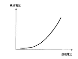
このため、基地局で各信号を正しく復調するには、各信号の受信レベルを揃える必要があるため、移動局において高度な電力制御が必要となる。特にCDMA方式にあっては広いダイナミックレンジや高リニアリティが要求され、中でも広帯域CDMA方式(W−CDMA等)では、大電力時の送信電力精度の要求が高い。しかし、送信電力を検波する際に用いられる検波ダイオードの検波特性は、図4に示すように、送信電力が小さい範囲では検波電圧の変化が小さな特性であるため、CDMA方式等で必要とされるような広いダイナミックレンジに対応した送信電力検出手段の実現は困難である。このため、送信電力精度の要求が高い大電力時のみ、送信電力を制御している。
【0004】
従来の無線通信装置の一例を図5に示す。同図に示す従来の無線通信装置は、アンテナ1および送受分離器2を備え、送受分離機2の受信系側には、無線受信部3と、復調器4と、ベースバンド信号処理部5とを備え、送受分離器2の送信系側には、前記ベースバンド信号処理部5と、変調器14と、無線送信部15とを備えている。なお、ベースバンド信号処理部5は受信系と送信系とで兼用して用いられている。さらに、本実施形態の無線通信装置は、送信電力補正機能を実現するために、制御信号発生部8と、送信電力検出部10と、誤差算出部11と、送信電力判定部7と、スイッチ部12と、加算部13とを備えている。
【0005】
以下、当該従来の無線通信装置が有する各構成要素について説明する。
まず、アンテナ1は、無線信号を送受信するものである。また、送受分離器2は、送信信号と受信信号を分離するものである。また、無線受信部3は、高周波増幅回路や局部発振回路、IF信号増幅回路等を含み、受信信号を高周波増幅する共にIF(中間周波)帯域に周波数変換したIF信号を出力するものである。
また、復調器4は、IF帯域に周波数変換された受信信号をベースバンド信号に変換するものである。
【0006】
また、ベースバンド信号処理部5は、ベースバンド信号の信号処理および復号化または符号化等を行うと共に、受信したベースバンド信号から送信電力制御ビットを抽出して、当該送信電力制御ビットに基づいて送信電力設定値24を出力するものである。なお、送信電力制御ビットとは、基地局での受信電力が一定になるように、移動局が自局の送信電力を制御するために基地局から送られてくるフィードバック情報のことである。また、送信電力設定値24とは、送信信号の所望の送信電力を示す値である。フィードバック情報を下りリンクを用いて伝送して移動局の送信電力を制御する方式を「クローズドループ送信電力制御」と呼ぶ。
【0007】
また、変調器14は、送信信号を変調してIF信号を出力するものである。また、無線送信部15は、送信信号の電力増幅およびRF(無線周波数)帯域への周波数変換を行うものであり、可変利得増幅器16を有している。可変利得増幅器16は、第2のゲイン制御信号23に基づいて電力増幅率(利得)が可変の、送信信号を電力増幅するものである。
【0008】
また、制御信号発生部8は、ベースバンド信号処理部5から出力された送信電力設定値24に応じた第1のゲイン制御信号22を出力するものである。また、送信電力検出部10は、アンテナ1から放射される送信電力を検出して検波信号18を出力するものである。また、誤差算出部11は、検波信号18と第1のゲイン制御信号22とを比較し、両者の誤差を算出して得られた誤差信号19を出力するものである。
【0009】
また、送信電力判定部7は、所定のしきい値に対する送信電力設定値24の大小関係を判定し、その判定結果に対応した動作制御信号21を出力するものである。また、スイッチ部12は、動作制御信号21により誤差信号19の経路の短絡または開放を切り替えるものである。また、加算部13は、誤差信号19を第1のゲイン制御信号22に加算して第2のゲイン制御信号23を出力するものである。なお、第2のゲイン制御信号23は、無線送信部15が有する可変利得増幅器16に入力される。
【0010】
このような構成の従来の無線通信装置では、基地局からの受信信号を復調して得られるベースバンド信号から、ベースバンド信号処理部5が送信電力制御ビットを抽出し、この送信電力制御ビットに基づいて送信電力設定値24を求め、制御信号発生部8が送信電力設定値24に基づいて第1のゲイン制御信号22を出力する。一方、アンテナ1から放射される送信電力を送信電力検出部10で検出し、この検出値(送信電力出力値)に対応する検波信号18と第1のゲイン制御信号22から、ベースバンド信号処理部5によって抽出された送信電力制御ビットに基づいて求められた送信電力設定値24と実際に送信されている送信電力出力値との誤差を誤差信号19として算出する。ここで、送信電力設定値24がしきい値に対して大きい場合、スイッチ部12により誤差信号の経路が短絡(オン)され、誤差信号19が加算部13に入力される。
【0011】
そして、この誤差信号19を第1のゲイン制御信号22に加算することにより第2のゲイン制御信号23を生成し、第2のゲイン制御信号23によって誤差信号19がゼロになるように送信電力利得を制御することで送信電力制御を行っている。すなわち、送信電力設定値24と送信電力出力値とを比較し、算出された誤差信号19を第1のゲイン制御信号22に加算することで、送信電力のフィードバック制御を行っている。
【0012】
【発明が解決しようとする課題】
しかしながら、上記説明した従来の無線通信装置にあっては、第2のゲイン制御信号23に送信系の温度補正や周波数補正を加えようとすると、誤差算出部11に入力される第1のゲイン制御信号22に温度特性や周波数特性の補正値が加わるため、誤差算出部11が正しい誤差を算出できず誤った送信電力に収束してしまう。このため、第2のゲイン制御信号23に送信系の温度特性や周波数特性の補正値を加えることができず、フィードバック制御による電力制御を行えない低電力時にあっては、送信電力の精度が劣化するという問題点があった。また、フィードバック制御による電力制御を行う大電力時でも、第2のゲイン制御信号23に温度特性や周波数特性の補正値が加算されていないため、加算されている場合と比較して送信系の温度特性や周波数特性が大きくなって、所望の送信電力と実際の送信電力の誤差が大きくなると、フィードバック制御による補正誤差も大きくなってしまうという問題点があった。
【0013】
本発明は、上記従来の問題点に鑑みてなされたものであって、送信系が有する温度特性または周波数特性に応じて利得の制御を行い、所望の送信電力で信号を送信することのできる無線通信装置を提供することを目的としている。
【0014】
【課題を解決するための手段】
上記目的を達成するために、本発明に係る無線通信装置は、送信信号を増幅する可変利得増幅手段の利得を前記送信信号が所望の送信電力となるよう制御する無線通信装置であって、受信信号を復調して得られたベースバンド信号から送信電力制御ビットを抽出し、当該送信電力制御ビットに基づいて所望の送信電力を示す送信電力設定情報を出力する設定情報発生手段と、信号を送信する送信系の温度特性または周波数特性に対する送信電力の補正情報を記憶する補正情報記憶手段と、前記補正情報記憶手段を参照して、当該無線通信装置の送信系が有する温度特性または周波数特性に対応した送信電力の補正情報を出力する補正情報発生手段と、前記設定情報発生手段から出力された送信電力設定情報および前記補正情報発生手段から出力された補正情報に基づいて、前記可変利得増幅手段の利得を制御するための第1のゲイン制御信号を出力する制御信号発生手段と、前記可変利得増幅手段によって増幅された送信信号の送信電力を検出して検波信号を出力する送信電力検出手段と、前記設定情報発生手段から出力された送信電力設定情報に応じた基準信号を出力する基準信号発生手段と、前記送信電力検出手段から出力された検波信号と前記基準信号発生手段から出力された基準信号との送信電力の差を算出して、当該送信信号の差を示す誤差信号を出力する誤差算出手段と、前記設定情報発生手段から出力された送信電力設定情報が示す送信電力と所定のしきい値との大小関係を判定して、その判定結果に応じた動作制御信号を出力する送信電力判定手段と、前記送信電力判定手段から出力された動作制御信号に応じて、前記誤差算出手段から出力された誤差信号の後段への経路を短絡または開放するスイッチ手段と、前記スイッチ手段を介して得られた誤差信号を前記制御信号発生手段から出力された第1のゲイン制御信号に加算して、前記可変利得増幅手段の利得を制御するための第2のゲイン制御信号を出力する第1の加算手段と、を備えている。
【0015】
このように、可変利得増幅手段の利得は第2のゲイン制御信号によって誤差信号がゼロになるよう制御されるため、送信信号の送信電力が送信電力設定情報の示す値となるように送信電力のフィードバック制御が行われる。第2のゲイン制御信号は、送信電力設定情報および補正情報に基づく第1のゲイン制御信号に誤差信号を加算した信号であり、誤差算出手段には補正情報は入力されず送信電力設定情報のみが入力されるため、可変利得増幅手段は、当該無線通信装置の送信系が有する温度特性または周波数特性に応じた利得の制御を精度良く行うことができる。結果として、所望の送信電力で信号を送信することができる。
【0016】
また、本発明に係る無線通信装置は、送信信号を増幅する可変利得増幅手段の利得を前記送信信号が所望の送信電力となるよう制御する無線通信装置であって、受信信号を復調して得られたベースバンド信号から送信電力制御ビットを抽出し、当該送信電力制御ビットに基づいて所望の送信電力を示す送信電力設定情報を出力する設定情報発生手段と、信号を送信する送信系の温度特性または周波数特性に対する送信電力の補正情報を記憶する補正情報記憶手段と、前記補正情報記憶手段を参照して、当該無線通信装置の送信系が有する温度特性または周波数特性に対応した送信電力の補正情報を出力する補正情報発生手段と、前記補正情報発生手段から出力された補正情報に基づいて、前記可変利得増幅手段の利得を制御するための補正信号を出力する補正信号発生手段と、前記可変利得増幅手段によって増幅された送信信号の送信電力を検出して検波信号を出力する送信電力検出手段と、前記設定情報発生手段から出力された送信電力設定情報に応じた基準信号を出力する基準信号発生手段と、前記送信電力検出手段から出力された検波信号と前記基準信号発生手段から出力された基準信号との送信電力の差を算出して、当該送信信号の差を示す誤差信号を出力する誤差算出手段と、前記設定情報発生手段から出力された送信電力設定情報が示す送信電力と所定のしきい値との大小関係を判定して、その判定結果に応じた動作制御信号を出力する送信電力判定手段と、前記送信電力判定手段から出力された動作制御信号に応じて、前記誤差算出手段から出力された誤差信号の後段への経路を短絡または開放するスイッチ手段と、前記補正信号発生手段から出力された補正信号と、前記基準信号発生手段から出力された基準信号と、前記スイッチ手段を介して得られた誤差信号とを加算して、前記可変利得増幅手段の利得を制御するための第2のゲイン制御信号を出力する第2の加算手段と、を備えている。
【0017】
このように、補正信号発生手段が補正情報のみに基づく補正信号を出力ており、当該補正信号と基準信号と誤差信号とを加算することで第2のゲイン制御信号を求めているため、可変利得増幅手段の利得の制御に必要な出力範囲と、温度特性や周波数特性による補正に必要な分解能を小さな回路規模で実現することができる。
【0018】
また、本発明に係る無線通信装置は、前記送信電力判定手段は、前記送信電力設定情報が示す送信電力が前記所定のしきい値以上の場合には前記スイッチ手段における誤差信号の経路を短絡するよう指示する動作制御信号を出力し、前記送信電力設定情報が示す送信電力が前記所定のしきい値未満の場合には前記スイッチ手段における誤差信号の経路を開放するよう指示する動作制御信号を出力する。したがって、検波特性の限界から決定されるしきい値に応じてフィードバック制御のオンオフ制御を行うことができる。
【0019】
また、本発明に係る無線通信装置は、前記送信電力判定手段から出力される動作制御信号は、前記誤差算出手段の動作をオンオフ制御することが望ましい。
【0020】
また、本発明に係る無線通信装置は、前記送信電力判定手段から出力される動作制御信号は、前記基準信号発生手段の動作をオンオフ制御することが望ましい。
【0021】
さらに、本発明に係る無線通信装置は、前記所定のしきい値は、前記送信電力検出部の検出限界に応じて決定されることが望ましい。
【0022】
【発明の実施の形態】
以下、本発明に係る無線通信装置の実施の形態について、〔第1の実施形態〕、〔第2の実施形態〕の順に図面を参照して詳細に説明する。
【0023】
〔第1の実施形態〕
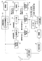
図1は、本発明に係る第1の実施形態の無線通信装置を示すブロック図である。同図において、図5(従来技術)と重複する部分には同一の符号が付されている。第1の実施形態の無線通信装置は、図1に示すように、アンテナ1および送受分離器2を備え、送受分離機2の受信系側には、無線受信部3と、復調器4と、ベースバンド信号処理部5とを備え、送受分離器2の送信系側には、特許請求の範囲の設定情報発生手段および補正情報発生手段に該当する前記ベースバンド信号処理部5と、変調器14と、無線送信部15とを備えている。なお、ベースバンド信号処理部5は受信系と送信系とで兼用して用いられている。
【0024】
さらに、本実施形態の無線通信装置は、送信電力補正機能を実現するために、補正情報記憶手段に該当するメモリ部9と、制御信号発生手段に該当する制御信号発生部8と、送信電力検出手段に該当する送信電力検出部10と、基準信号発生手段に該当する基準信号発生部6と、誤差算出手段に該当する誤差算出部11と、送信電力判定手段に該当する送信電力判定部7と、スイッチ手段に該当するスイッチ部12と、第1の加算手段に該当する加算部13とを備えている。
【0025】
以下、本実施形態の無線通信装置が有する各構成要素について説明する。
まず、アンテナ1は、無線信号を送受信するものである。また、送受分離器2は、送信信号と受信信号を分離するものである。また、無線受信部3は、高周波増幅回路や局部発振回路、IF信号増幅回路等を含み、受信信号を高周波増幅する共にIF(中間周波)帯域に周波数変換したIF信号を出力するものである。
また、復調器4は、IF帯域に周波数変換された受信信号をベースバンド信号に変換するものである。
【0026】
また、ベースバンド信号処理部5は、ベースバンド信号の信号処理および復号化または符号化等を行うと共に、受信したベースバンド信号から送信電力制御ビットを抽出して、当該送信電力制御ビットに基づいて特許請求の範囲の送信電力設定情報に該当する送信電力設定値24を出力し、かつ、メモリ部9を参照して本実施形態の無線通信装置の送信系が有する温度特性および周波数特性に対応した補正情報に該当する温度・周波数補正値25を出力するものである。なお、送信電力制御ビットとは、基地局での受信電力が一定になるように、移動局が自局の送信電力を制御するために基地局から送られてくるフィードバック情報のことである。また、送信電力設定値24とは、送信信号の所望の送信電力を示す値である。フィードバック情報を下りリンクを用いて伝送して移動局の送信電力を制御する方式を「クローズドループ送信電力制御」と呼ぶ。
【0027】
また、メモリ部9は、送信系の温度特性や周波数特性に対する温度・周波数補正値のテーブルを記憶するものである。また、変調器14は、送信信号を変調してIF信号を出力するものである。また、無線送信部15は、送信信号の電力増幅およびRF(無線周波数)帯域への周波数変換を行うものであり、可変利得増幅器16を有している。可変利得増幅器16は、第2のゲイン制御信号23に基づいて電力増幅率(利得)が可変の、送信信号を電力増幅するものである。
【0028】
また、制御信号発生部8は、ベースバンド信号処理部5から出力された送信電力設定値24および温度・周波数補正値25に応じた第1のゲイン制御信号22を出力するものである。また、送信電力検出部10は、アンテナ1から送信される信号の送信電力を検出して検波信号18を出力するものであり、検波ダイオード等によって構成される。また、基準信号発生部6は、送信電力設定値24に応じた基準信号20を出力するものである。また、誤差算出部11は、検波信号18と基準信号20とを比較し、両者の誤差を算出して得られた誤差信号19を出力するものである。
【0029】
また、送信電力判定部7は、所定のしきい値に対する送信電力設定値24の大小関係を判定し、その判定結果に対応した動作制御信号21を出力するものである。また、スイッチ部12は、動作制御信号21により誤差信号19の経路の短絡または開放を切り替えるものである。また、加算部13は、誤差信号19を第1のゲイン制御信号22に加算して第2のゲイン制御信号23を出力するものである。なお、第2のゲイン制御信号23は、無線送信部15が有する可変利得増幅器16に入力される。
【0030】
次に、本実施形態の無線通信装置の動作について説明する。
まず、基地局(図示せず)から送信された信号がアンテナ1で受信されると、この受信信号は送受分離器2を経由して無線受信部3に入力される。当該受信信号は無線受信部3でIF帯に周波数変換された後、復調器4によってベースバンド信号に変換され、ベースバンド信号処理部5に入力される。ベースバンド信号処理部5は、当該ベースバンド信号から送信電力制御ビットを抽出し、当該抽出された送信電力制御ビットに基づいて送信電力設定値24を求め、基準信号発生部6、送信電力判定部7および制御信号発生部8に出力する。また、ベースバンド信号処理部5は、メモリ部9に記憶されているテーブルを参照して、本実施形態の無線通信装置の送信系が有する温度特性および周波数特性に対応した温度・周波数補正値25を読み出し、制御信号発生部8に出力する。制御信号発生部8は、ベースバンド信号処理部5から送られた送信電力設定値24および温度・周波数補正値25に基づいて第1のゲイン制御信号22を求め、加算部13に出力する。
【0031】
一方、送信信号は変調器14で変調されてIF信号となり、無線送信部15でRF帯域の周波数に周波数変換および増幅された後、送受分離器2を経由してアンテナ1から基地局等の相手局に送信される。このとき、無線送信部15と送受分離器2との間における送信信号の送信電力が送信電力検出部10によって検波される。送信電力検出部10は、当該送信信号の送信電力を検出して検波信号18を誤差算出部11に出力する。一方、基準信号発生部6は、ベースバンド処理部5から受け取った送信電力設定値24に応じた基準信号20を誤差算出部11に出力する。誤差算出部11では、送信電力検出部10から得られた検波信号18および基準信号発生部6から得られた基準信号20に基づいて、設定された送信電力に対する実際の送信電力の誤差を算出し、当該算出された誤差を示す誤差信号19を出力する。
【0032】
また、送信電力判定部7は、ベースバンド処理部5から受け取った送信電力設定値24と所定のしきい値とを比較して、所定の比較に対する送信電力設定値24の大小関係を判定する。そして、この判定結果に対応した動作制御信号21をスイッチ部12に出力する。スイッチ部12は、当該動作制御信号21に従って、送信電力設定値24が所定のしきい値以上の場合には誤差算出部11から送られた誤差信号19の経路を短絡し、誤差信号19を加算部13に入力する。一方、送信電力設定値24が所定のしきい値未満の場合には誤差信号19の経路を開放し、加算部13には何も入力しない。
【0033】
次に、加算部13は、誤差信号を19が入力されれば当該誤差信号19と第1のゲイン制御信号22を加算して第2のゲイン制御信号23を出力し、誤差信号19が入力されなければ第1のゲイン制御信号22を第2のゲイン制御信号23として出力する。加算部13から出力された第2のゲイン制御信号23は無線送信部15が有する可変利得増幅器16に入力され、可変利得増幅器16は、第2のゲイン制御信号23に基づいて送信信号の電力増幅率(利得)を変え、送信信号を電力増幅する。
【0034】
図2に、本実施形態の無線通信装置における(a)送信電力設定値24、(b)ゲイン制御信号、(c)誤差信号19および(d)スイッチ部12の出力のタイミングチャートを示す。同図に示すように、送信電力設定値24としきい値との大小関係に応じて、送信電力設定値24がしきい値以上であれば自動電力制御を動作させる(APC制御ON)動作制御信号21を出力して、スイッチ部12において誤差信号19の経路を短絡させ、誤差信号19を加算部13に入力する。一方、送信電力設定値24がしきい値未満であれば自動電力制御を動作させない(APC制御OFF)動作制御信号21を出力して、スイッチ部12において誤差信号19を開放させ、加算部13には誤差信号19を入力しない。
【0035】
以上説明したように、本実施形態の無線通信装置にあっては、可変利得増幅器16の利得は第2のゲイン制御信号23によって誤差信号19がゼロになるよう制御されるため、無線送信部15から出力される送信電力が送信電力設定値24となるように送信電力のフィードバック制御を行っている。第2のゲイン制御信号23は、送信電力設定値24および温度・周波数補正値25に基づく第1のゲイン制御信号22に誤差信号19を加算した信号であり、誤差算出部11には温度・周波数補正値25は入力されず送信電力設定値24のみが入力されるため、可変利得増幅器16は、本実施形態の無線通信装置の送信系が有する温度特性および周波数特性に応じた利得の制御を精度良く行うことができる。結果として、所望の送信電力で信号を送信する無線通信装置を提供することができる。
【0036】
また、第2のゲイン制御信号23に温度・周波数補正を加えることで、しきい値以下の送信電力(APC制御OFF時)における電力精度を向上させることができる。また、自動電力制御(APC)は、APC制御OFF時の送信電力誤差が大きいほど、APC制御ON時に補正誤差が残るため、APC制御OFF時の送信電力精度を向上させることでAPC制御ON時の送信電力精度を向上させることができる。さらに、しきい値以上の送信電力においても、送信電力の検出精度が良いため補正誤差は小さくなり、高精度のフィードバック制御を行うことができる。
【0037】
〔第2の実施形態〕
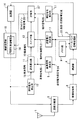
図3は、本発明に係る第2の実施形態の無線通信装置を示すブロック図である。同図において、図1(第1の実施形態)と重複する部分には同一の符号を付して説明を省略する。第2の実施形態の無線通信装置が第1の実施形態の無線通信装置と異なる点は、送信電力設定値24および温度・周波数補正値25に応じた第1のゲイン制御信号22を出力する制御信号発生部8の代わりに、温度・周波数補正値25のみに応じた補正信号26を出力する特許請求の範囲の補正信号発生手段に該当する補正信号発生部17を備えた点である。
【0038】
また、第1の実施形態の加算部13の代わりに、第2の加算手段に該当する加算部27を備えている。本実施形態では、基準信号発生部6から出力された基準信号20は誤差算出部11だけでなく加算部27にも入力されるため、本実施形態の加算部27は、補正信号26および基準信号20に誤差信号19を加算して第2のゲイン制御信号28を出力する。なお、第2のゲイン制御信号28は、第1の実施形態と同様に、無線送信部15が有する可変利得増幅器16に入力される。
【0039】
このため、本実施形態の無線通信装置にあっては、可変利得増幅器16の利得は第2のゲイン制御信号28によって誤差信号19がゼロになるよう制御されるため、無線送信部15から出力される送信電力が送信電力設定値24となるように送信電力のフィードバック制御を行っている。第1の実施形態の無線通信装置では、制御信号発生部8に可変利得増幅器16の制御に必要な出力範囲と、温度特性や周波数特性による補正に必要な分解能とを持たせるため、制御信号発生部8の回路規模は比較的大きくなってしまうが、本実施形態では、補正信号発生部17が温度・周波数補正値25のみに基づいて補正信号26を求めており、当該補正信号26および基準信号20に誤差信号19を加算することで第2のゲイン制御信号28を求めているため、第1の実施形態と同様に、可変利得増幅器16の制御に必要な出力範囲と、温度特性や周波数特性による補正に必要な分解能を第1の実施形態よりも小さな回路規模で実現することができる。
【0040】
なお、第1および第2の実施形態では、送信電力検出部10の検出限界に応じてしきい値を調整することで送信電力の制御範囲を変更することができる。また、送信電力判定部7が送信電力設定値24のしきい値に対する大小判定に応じて、スイッチ部12で誤差信号19の経路を短絡(オン)または開放(オフ)しているが、誤差算出部11の動作をオンオフ制御したり、基準信号発生部6の動作をオンオフ制御しても良い。この場合、スイッチ部12でオンオフ制御する場合と比較して、消費電力の削減を図ることができる。さらに、送信電力判定部7で用いられるしきい値は、送信電力検出部10を構成する検波ダイオードの検出特性(検出限界)に応じて決定される値である。
【0041】
【発明の効果】
以上説明したように、本発明に係る無線通信装置によれば、可変利得増幅手段の利得は第2のゲイン制御信号によって誤差信号がゼロになるよう制御されるため、送信信号の送信電力が送信電力設定情報の示す値となるように送信電力のフィードバック制御が行われる。第2のゲイン制御信号は、送信電力設定情報および補正情報に基づく第1のゲイン制御信号に誤差信号を加算した信号であり、誤差算出手段には補正情報は入力されず送信電力設定情報のみが入力されるため、可変利得増幅手段は、当該無線通信装置の送信系が有する温度特性または周波数特性に応じた利得の制御を精度良く行うことができる。結果として、所望の送信電力で信号を送信することができる。
【図面の簡単な説明】
【図1】本発明に係る第1の実施形態の無線通信装置を示すブロック図
【図2】第1の実施形態の無線通信装置における(a)送信電力設定値24、(b)ゲイン制御信号、(c)誤差信号19および(d)スイッチ部12の出力のタイミングチャート
【図3】本発明に係る第2の実施形態の無線通信装置を示すブロック図
【図4】送信電力検出部の入出力特性を示す説明図
【図5】従来の無線通信装置を示すブロック図
【符号の説明】
1 アンテナ
2 送受分離器
3 無線受信部
4 復調器
5 ベースバンド信号処理部
6 基準信号発生部
7 送信電力判定部
8 制御信号発生部
9 メモリ部
10 送信電力検出部
11 誤差算出部
12 スイッチ部
13 加算部
14 変調器
15 無線送信部
16 可変利得増幅器
17 補正信号発生部[0001]
TECHNICAL FIELD OF THE INVENTION
The present invention relates to a wireless communication device that controls transmission power of a transmission system to a desired value.
[0002]
[Prior art]
In a conventional mobile communication system, by controlling the transmission power of the mobile station according to the distance to the base station, the power of a signal received by the base station is kept constant, and interference between communication channels is suppressed, thereby reducing the frequency. Improves usage efficiency. However, in a CDMA mobile communication system, the same frequency band can be shared by a plurality of users at the same time, but when the transmission power of the mobile station is constant regardless of the distance from the base station or the transmission environment, There is a problem that a signal from a near mobile station received by the base station is too strong to separate a signal from a far mobile station.
[0003]
For this reason, in order for the base station to correctly demodulate each signal, it is necessary to equalize the reception level of each signal, so that the mobile station requires advanced power control. In particular, a wide dynamic range and high linearity are required in the CDMA system, and particularly, in a wideband CDMA system (W-CDMA or the like), there is a high demand for transmission power accuracy at high power. However, as shown in FIG. 4, the detection characteristics of the detection diode used for detecting the transmission power are required in a CDMA system or the like because the detection voltage changes little in a range where the transmission power is small. It is difficult to realize a transmission power detection unit that supports such a wide dynamic range. For this reason, the transmission power is controlled only at the time of high power where the demand for transmission power accuracy is high.
[0004]
FIG. 5 shows an example of a conventional wireless communication device. The conventional wireless communication device shown in FIG. 1 includes an antenna 1 and a transmission /
[0005]
Hereinafter, each component of the conventional wireless communication device will be described.
First, the antenna 1 transmits and receives a radio signal. The transmission /
Further, the demodulator 4 converts the received signal frequency-converted into the IF band into a baseband signal.
[0006]
In addition, the baseband
[0007]
The
[0008]
Further, the control signal generator 8 outputs a first gain control signal 22 corresponding to the transmission power set value 24 output from the
[0009]
The transmission
[0010]
In the conventional wireless communication apparatus having such a configuration, the baseband
[0011]
Then, a second gain control signal 23 is generated by adding the error signal 19 to the first gain control signal 22, and the transmission power gain is set so that the error signal 19 becomes zero by the second gain control signal 23. Is controlled to control the transmission power. That is, the transmission power set value 24 is compared with the transmission power output value, and the feedback control of the transmission power is performed by adding the calculated error signal 19 to the first gain control signal 22.
[0012]
[Problems to be solved by the invention]
However, in the above-described conventional wireless communication apparatus, if an attempt is made to add temperature correction or frequency correction of the transmission system to the second gain control signal 23, the first gain control input to the
[0013]
The present invention has been made in view of the above-described conventional problems, and has been made in consideration of the above-described problem, and has been made in consideration of a problem that a gain can be controlled in accordance with a temperature characteristic or a frequency characteristic of a transmission system so that a signal can be transmitted with desired transmission power. It is intended to provide a communication device.
[0014]
[Means for Solving the Problems]
In order to achieve the above object, a wireless communication apparatus according to the present invention is a wireless communication apparatus that controls a gain of a variable gain amplifying means for amplifying a transmission signal so that the transmission signal has a desired transmission power, Setting information generating means for extracting transmission power control bits from a baseband signal obtained by demodulating a signal and outputting transmission power setting information indicating desired transmission power based on the transmission power control bits; Correction information storage means for storing transmission power correction information for the temperature characteristic or frequency characteristic of the transmission system to perform, and referring to the correction information storage means, corresponding to the temperature characteristic or frequency characteristic of the transmission system of the wireless communication device. Correction information generating means for outputting corrected transmission power correction information, and transmission power setting information output from the setting information generating means and output from the correction information generating means. Control signal generating means for outputting a first gain control signal for controlling the gain of the variable gain amplifying means based on the corrected information, and transmitting power of the transmission signal amplified by the variable gain amplifying means. Transmission power detection means for detecting and outputting a detection signal, reference signal generation means for outputting a reference signal according to the transmission power setting information output from the setting information generation means, and output from the transmission power detection means An error calculator that calculates a difference in transmission power between the detection signal and the reference signal output from the reference signal generator, and outputs an error signal indicating the difference between the transmission signals, and an output from the setting information generator. Transmission power determining means for determining a magnitude relationship between the transmission power indicated by the transmission power setting information and a predetermined threshold value, and outputting an operation control signal according to the determination result; Switch means for short-circuiting or opening a path to a subsequent stage of the error signal output from the error calculation means in accordance with the operation control signal output from the determination means; and an error signal obtained via the switch means, First adding means for adding a first gain control signal output from the control signal generating means and outputting a second gain control signal for controlling the gain of the variable gain amplifying means. I have.
[0015]
As described above, since the gain of the variable gain amplifying means is controlled by the second gain control signal so that the error signal becomes zero, the transmission power of the transmission signal becomes equal to the value indicated by the transmission power setting information. Feedback control is performed. The second gain control signal is a signal obtained by adding an error signal to the first gain control signal based on the transmission power setting information and the correction information, and only the transmission power setting information is not input to the error calculating means. Since the input is input, the variable gain amplifying unit can accurately control the gain according to the temperature characteristic or the frequency characteristic of the transmission system of the wireless communication device. As a result, a signal can be transmitted with a desired transmission power.
[0016]
Further, a wireless communication apparatus according to the present invention is a wireless communication apparatus which controls a gain of a variable gain amplifying means for amplifying a transmission signal so that the transmission signal has a desired transmission power, and obtains a signal by demodulating a reception signal. Setting information generating means for extracting transmission power control bits from the obtained baseband signal and outputting transmission power setting information indicating desired transmission power based on the transmission power control bits, and temperature characteristics of a transmission system for transmitting the signal Or, correction information storage means for storing transmission power correction information for frequency characteristics, and, with reference to the correction information storage means, transmission power correction information corresponding to temperature characteristics or frequency characteristics of the transmission system of the wireless communication device. And a correction signal for controlling the gain of the variable gain amplifying means based on the correction information output from the correction information generating means. , A transmission power detection unit that detects the transmission power of the transmission signal amplified by the variable gain amplification unit and outputs a detection signal, and a transmission power setting output from the setting information generation unit. A reference signal generating means for outputting a reference signal according to the information, and calculating a difference in transmission power between a detection signal output from the transmission power detecting means and a reference signal output from the reference signal generating means, Error calculating means for outputting an error signal indicating a difference between transmission signals; and a magnitude relationship between transmission power indicated by transmission power setting information output from the setting information generating means and a predetermined threshold value is determined. Transmission power determining means for outputting an operation control signal according to the result; and an operation control signal output from the transmission power determination means, and Switch means for short-circuiting or opening the path to the correction signal output from the correction signal generation means, a reference signal output from the reference signal generation means, and an error signal obtained via the switch means. And a second adding means for outputting a second gain control signal for controlling the gain of the variable gain amplifying means.
[0017]
As described above, the correction signal generating means outputs the correction signal based only on the correction information, and obtains the second gain control signal by adding the correction signal, the reference signal, and the error signal. The output range required for controlling the gain of the amplifying means and the resolution required for correction based on temperature characteristics and frequency characteristics can be realized with a small circuit scale.
[0018]
Further, in the wireless communication apparatus according to the present invention, the transmission power determination unit short-circuits an error signal path in the switch unit when the transmission power indicated by the transmission power setting information is equal to or more than the predetermined threshold. And outputting an operation control signal instructing to open a path of the error signal in the switch means when the transmission power indicated by the transmission power setting information is less than the predetermined threshold. I do. Therefore, the on / off control of the feedback control can be performed according to the threshold value determined from the limit of the detection characteristic.
[0019]
Further, in the wireless communication apparatus according to the present invention, it is preferable that the operation control signal output from the transmission power determination unit controls on / off of the operation of the error calculation unit.
[0020]
Further, in the wireless communication apparatus according to the present invention, it is preferable that the operation control signal output from the transmission power determination unit controls on / off of the operation of the reference signal generation unit.
[0021]
Further, in the wireless communication apparatus according to the present invention, it is preferable that the predetermined threshold is determined according to a detection limit of the transmission power detection unit.
[0022]
BEST MODE FOR CARRYING OUT THE INVENTION
Hereinafter, embodiments of a wireless communication apparatus according to the present invention will be described in detail with reference to the drawings in the order of [first embodiment] and [second embodiment].
[0023]
[First Embodiment]
FIG. 1 is a block diagram illustrating a wireless communication device according to a first embodiment of the present invention. In the figure, the same reference numerals are given to the portions that overlap with FIG. 5 (prior art). As shown in FIG. 1, the wireless communication device according to the first embodiment includes an antenna 1 and a transmission /
[0024]
Further, in order to realize the transmission power correction function, the wireless communication apparatus of the present embodiment includes a
[0025]
Hereinafter, each component of the wireless communication device of the present embodiment will be described.
First, the antenna 1 transmits and receives a radio signal. The transmission /
Further, the demodulator 4 converts the received signal frequency-converted into the IF band into a baseband signal.
[0026]
In addition, the baseband
[0027]
The
[0028]
Further, the control signal generator 8 outputs a first gain control signal 22 corresponding to the transmission power set value 24 and the temperature / frequency correction value 25 output from the
[0029]
The transmission
[0030]
Next, the operation of the wireless communication device according to the present embodiment will be described.
First, when a signal transmitted from a base station (not shown) is received by the antenna 1, the received signal is input to the wireless receiving unit 3 via the transmission /
[0031]
On the other hand, the transmission signal is modulated by the
[0032]
Further, the transmission
[0033]
Next, when the error signal 19 is input, the
[0034]
FIG. 2 shows a timing chart of (a) the transmission power set value 24, (b) the gain control signal, (c) the error signal 19, and (d) the output of the
[0035]
As described above, in the wireless communication device of the present embodiment, the gain of the
[0036]
Further, by adding the temperature and frequency correction to the second gain control signal 23, it is possible to improve the power accuracy when the transmission power is equal to or less than the threshold value (when the APC control is OFF). In addition, in the automatic power control (APC), the larger the transmission power error when the APC control is off, the more the correction error remains when the APC control is on. Transmission power accuracy can be improved. Further, even at a transmission power equal to or higher than the threshold value, the correction error is small because the detection accuracy of the transmission power is good, and highly accurate feedback control can be performed.
[0037]
[Second embodiment]
FIG. 3 is a block diagram illustrating a wireless communication device according to a second embodiment of the present invention. In the figure, the same reference numerals are given to the same parts as those in FIG. 1 (first embodiment), and the description will be omitted. The difference between the wireless communication device of the second embodiment and the wireless communication device of the first embodiment is that the wireless communication device outputs a first gain control signal 22 corresponding to a transmission power set value 24 and a temperature / frequency correction value 25. Instead of the signal generator 8, a correction signal generator 17 corresponding to the correction signal generator according to the claims that outputs a correction signal 26 corresponding to only the temperature / frequency correction value 25 is provided.
[0038]
Further, instead of the adding
[0039]
For this reason, in the wireless communication device of the present embodiment, the gain of the
[0040]
In the first and second embodiments, the control range of the transmission power can be changed by adjusting the threshold according to the detection limit of the transmission
[0041]
【The invention's effect】
As described above, according to the wireless communication apparatus of the present invention, the gain of the variable gain amplifying means is controlled by the second gain control signal so that the error signal becomes zero, so that the transmission power of the transmission signal is reduced. Feedback control of the transmission power is performed so as to be a value indicated by the power setting information. The second gain control signal is a signal obtained by adding an error signal to the first gain control signal based on the transmission power setting information and the correction information, and only the transmission power setting information is not input to the error calculating means. Since the input is input, the variable gain amplifying unit can accurately control the gain according to the temperature characteristic or the frequency characteristic of the transmission system of the wireless communication device. As a result, a signal can be transmitted with a desired transmission power.
[Brief description of the drawings]
FIG. 1 is a block diagram showing a wireless communication device according to a first embodiment of the present invention.
FIG. 2 is a timing chart of (a) a transmission power set value 24, (b) a gain control signal, (c) an error signal 19, and (d) an output of a
FIG. 3 is a block diagram showing a wireless communication device according to a second embodiment of the present invention;
FIG. 4 is an explanatory diagram showing input / output characteristics of a transmission power detection unit.
FIG. 5 is a block diagram showing a conventional wireless communication device.
[Explanation of symbols]
1 antenna
2 Transmitter / receiver separator
3 Radio receiver
4 Demodulator
5 Baseband signal processing unit
6 Reference signal generator
7 Transmission power judgment unit
8 Control signal generator
9 Memory section
10 Transmission power detector
11 Error calculator
12 Switch section
13 Addition unit
14 Modulator
15 Wireless transmitter
16 Variable gain amplifier
17 Correction signal generator
Claims (6)
受信信号を復調して得られたベースバンド信号から送信電力制御ビットを抽出し、当該送信電力制御ビットに基づいて所望の送信電力を示す送信電力設定情報を出力する設定情報発生手段と、
信号を送信する送信系の温度特性または周波数特性に対する送信電力の補正情報を記憶する補正情報記憶手段と、
前記補正情報記憶手段を参照して、当該無線通信装置の送信系が有する温度特性または周波数特性に対応した送信電力の補正情報を出力する補正情報発生手段と、
前記設定情報発生手段から出力された送信電力設定情報および前記補正情報発生手段から出力された補正情報に基づいて、前記可変利得増幅手段の利得を制御するための第1のゲイン制御信号を出力する制御信号発生手段と、
前記可変利得増幅手段によって増幅された送信信号の送信電力を検出して検波信号を出力する送信電力検出手段と、
前記設定情報発生手段から出力された送信電力設定情報に応じた基準信号を出力する基準信号発生手段と、
前記送信電力検出手段から出力された検波信号と前記基準信号発生手段から出力された基準信号との送信電力の差を算出して、当該送信信号の差を示す誤差信号を出力する誤差算出手段と、
前記設定情報発生手段から出力された送信電力設定情報が示す送信電力と所定のしきい値との大小関係を判定して、その判定結果に応じた動作制御信号を出力する送信電力判定手段と、
前記送信電力判定手段から出力された動作制御信号に応じて、前記誤差算出手段から出力された誤差信号の後段への経路を短絡または開放するスイッチ手段と、
前記スイッチ手段を介して得られた誤差信号を前記制御信号発生手段から出力された第1のゲイン制御信号に加算して、前記可変利得増幅手段の利得を制御するための第2のゲイン制御信号を出力する第1の加算手段と、を備えたことを特徴とする無線通信装置。A wireless communication device that controls a gain of a variable gain amplifying unit that amplifies a transmission signal so that the transmission signal has a desired transmission power,
Setting information generating means for extracting a transmission power control bit from a baseband signal obtained by demodulating the received signal and outputting transmission power setting information indicating desired transmission power based on the transmission power control bit;
Correction information storage means for storing transmission power correction information for temperature characteristics or frequency characteristics of a transmission system for transmitting a signal,
With reference to the correction information storage unit, a correction information generation unit that outputs correction information of transmission power corresponding to a temperature characteristic or a frequency characteristic of a transmission system of the wireless communication device,
A first gain control signal for controlling a gain of the variable gain amplifying means is output based on the transmission power setting information output from the setting information generating means and the correction information output from the correction information generating means. Control signal generating means;
Transmission power detection means for detecting the transmission power of the transmission signal amplified by the variable gain amplification means and outputting a detection signal,
Reference signal generating means for outputting a reference signal according to the transmission power setting information output from the setting information generating means,
Error calculation means for calculating a difference in transmission power between the detection signal output from the transmission power detection means and the reference signal output from the reference signal generation means, and outputting an error signal indicating the difference between the transmission signals; ,
Transmission power determination means for determining the magnitude relationship between the transmission power indicated by the transmission power setting information output from the setting information generating means and a predetermined threshold, and outputting an operation control signal according to the determination result,
Switch means for short-circuiting or opening a path to a subsequent stage of the error signal output from the error calculation means according to the operation control signal output from the transmission power determination means,
A second gain control signal for controlling the gain of the variable gain amplifier by adding an error signal obtained through the switch to the first gain control signal output from the control signal generator; And a first adding means for outputting a signal.
受信信号を復調して得られたベースバンド信号から送信電力制御ビットを抽出し、当該送信電力制御ビットに基づいて所望の送信電力を示す送信電力設定情報を出力する設定情報発生手段と、
信号を送信する送信系の温度特性または周波数特性に対する送信電力の補正情報を記憶する補正情報記憶手段と、
前記補正情報記憶手段を参照して、当該無線通信装置の送信系が有する温度特性または周波数特性に対応した送信電力の補正情報を出力する補正情報発生手段と、
前記補正情報発生手段から出力された補正情報に基づいて、前記可変利得増幅手段の利得を制御するための補正信号を出力する補正信号発生手段と、
前記可変利得増幅手段によって増幅された送信信号の送信電力を検出して検波信号を出力する送信電力検出手段と、
前記設定情報発生手段から出力された送信電力設定情報に応じた基準信号を出力する基準信号発生手段と、
前記送信電力検出手段から出力された検波信号と前記基準信号発生手段から出力された基準信号との送信電力の差を算出して、当該送信信号の差を示す誤差信号を出力する誤差算出手段と、
前記設定情報発生手段から出力された送信電力設定情報が示す送信電力と所定のしきい値との大小関係を判定して、その判定結果に応じた動作制御信号を出力する送信電力判定手段と、
前記送信電力判定手段から出力された動作制御信号に応じて、前記誤差算出手段から出力された誤差信号の後段への経路を短絡または開放するスイッチ手段と、
前記補正信号発生手段から出力された補正信号と、前記基準信号発生手段から出力された基準信号と、前記スイッチ手段を介して得られた誤差信号とを加算して、前記可変利得増幅手段の利得を制御するための第2のゲイン制御信号を出力する第2の加算手段と、を備えたことを特徴とする無線通信装置。A wireless communication device that controls a gain of a variable gain amplifying unit that amplifies a transmission signal so that the transmission signal has a desired transmission power,
Setting information generating means for extracting a transmission power control bit from a baseband signal obtained by demodulating the received signal and outputting transmission power setting information indicating desired transmission power based on the transmission power control bit;
Correction information storage means for storing transmission power correction information for temperature characteristics or frequency characteristics of a transmission system for transmitting a signal,
With reference to the correction information storage unit, a correction information generation unit that outputs correction information of transmission power corresponding to a temperature characteristic or a frequency characteristic of a transmission system of the wireless communication device,
Correction signal generating means for outputting a correction signal for controlling the gain of the variable gain amplifying means based on the correction information output from the correction information generating means;
Transmission power detection means for detecting the transmission power of the transmission signal amplified by the variable gain amplification means and outputting a detection signal,
Reference signal generating means for outputting a reference signal according to the transmission power setting information output from the setting information generating means,
Error calculation means for calculating a difference in transmission power between the detection signal output from the transmission power detection means and the reference signal output from the reference signal generation means, and outputting an error signal indicating the difference between the transmission signals; ,
Transmission power determination means for determining the magnitude relationship between the transmission power indicated by the transmission power setting information output from the setting information generating means and a predetermined threshold, and outputting an operation control signal according to the determination result,
Switch means for short-circuiting or opening a path to a subsequent stage of the error signal output from the error calculation means according to the operation control signal output from the transmission power determination means,
The correction signal output from the correction signal generating means, the reference signal output from the reference signal generating means, and an error signal obtained through the switch means are added, and the gain of the variable gain amplifying means is added. And a second adding means for outputting a second gain control signal for controlling the wireless communication device.
前記送信電力設定情報が示す送信電力が前記所定のしきい値以上の場合には前記スイッチ手段における誤差信号の経路を短絡するよう指示する動作制御信号を出力し、
前記送信電力設定情報が示す送信電力が前記所定のしきい値未満の場合には前記スイッチ手段における誤差信号の経路を開放するよう指示する動作制御信号を出力することを特徴とする請求項1または2記載の無線通信装置。The transmission power determination means,
When the transmission power indicated by the transmission power setting information is equal to or more than the predetermined threshold, an operation control signal for instructing to short-circuit the path of the error signal in the switch unit is output,
2. An operation control signal for instructing to open a path of an error signal in said switch means when a transmission power indicated by said transmission power setting information is less than said predetermined threshold value. 3. The wireless communication device according to 2.
Priority Applications (1)
| Application Number | Priority Date | Filing Date | Title |
|---|---|---|---|
| JP2003003379A JP2004221663A (en) | 2003-01-09 | 2003-01-09 | Wireless communication device |
Applications Claiming Priority (1)
| Application Number | Priority Date | Filing Date | Title |
|---|---|---|---|
| JP2003003379A JP2004221663A (en) | 2003-01-09 | 2003-01-09 | Wireless communication device |
Publications (1)
| Publication Number | Publication Date |
|---|---|
| JP2004221663A true JP2004221663A (en) | 2004-08-05 |
Family
ID=32894661
Family Applications (1)
| Application Number | Title | Priority Date | Filing Date |
|---|---|---|---|
| JP2003003379A Pending JP2004221663A (en) | 2003-01-09 | 2003-01-09 | Wireless communication device |
Country Status (1)
| Country | Link |
|---|---|
| JP (1) | JP2004221663A (en) |
Cited By (4)
| Publication number | Priority date | Publication date | Assignee | Title |
|---|---|---|---|---|
| JP2006121420A (en) * | 2004-10-21 | 2006-05-11 | Nec Corp | Radio communication equipment and transmission power control method |
| JP2006279201A (en) * | 2005-03-28 | 2006-10-12 | Toshiba Tec Corp | Wireless tag reader |
| JP2016001865A (en) * | 2014-05-21 | 2016-01-07 | パナソニックIpマネジメント株式会社 | Detection calibration circuit and transmitter |
| JP2016184890A (en) * | 2015-03-26 | 2016-10-20 | 京セラ株式会社 | Wireless communication apparatus and wireless communication method |
-
2003
- 2003-01-09 JP JP2003003379A patent/JP2004221663A/en active Pending
Cited By (4)
| Publication number | Priority date | Publication date | Assignee | Title |
|---|---|---|---|---|
| JP2006121420A (en) * | 2004-10-21 | 2006-05-11 | Nec Corp | Radio communication equipment and transmission power control method |
| JP2006279201A (en) * | 2005-03-28 | 2006-10-12 | Toshiba Tec Corp | Wireless tag reader |
| JP2016001865A (en) * | 2014-05-21 | 2016-01-07 | パナソニックIpマネジメント株式会社 | Detection calibration circuit and transmitter |
| JP2016184890A (en) * | 2015-03-26 | 2016-10-20 | 京セラ株式会社 | Wireless communication apparatus and wireless communication method |
Similar Documents
| Publication | Publication Date | Title |
|---|---|---|
| US6166598A (en) | Power amplifying circuit with supply adjust to control adjacent and alternate channel power | |
| US6741867B1 (en) | Non-linear distortion compensation circuit, transmitter device to be employed in the same and mobile communication unit | |
| US7039373B2 (en) | Wireless communication apparatus and transmission power control method thereof | |
| TWI528712B (en) | Amplifier gain adjustment in response to reduced supply voltage | |
| TWI462508B (en) | Closed-loop adaptive power control for adjusting bandwidth in a mobile handset transmitter | |
| JP2001111480A (en) | Wireless communication device and transmission power control method | |
| JP2000196521A (en) | Wireless communication device and transmission power control method in wireless communication device | |
| US7496163B2 (en) | AGC system, AGC method, and receiver using the AGC system | |
| US9876515B2 (en) | Adaptive transmitter efficiency optimization | |
| CN101442794B (en) | Method for controlling wireless terminal emission power and wireless terminal | |
| JP3970177B2 (en) | Wireless communication device | |
| JP2004221663A (en) | Wireless communication device | |
| US6404757B1 (en) | Reception method and apparatus in CDMA system | |
| JP3197467B2 (en) | Transmission output control device | |
| US20100184389A1 (en) | Wireless communication unit, integrated circuit and method for biasing a power amplifier | |
| JP2004007083A (en) | Transmission device | |
| US7532905B2 (en) | Filter device and transmission power control apparatus | |
| JP5267389B2 (en) | Transmitting apparatus and transmitting method | |
| JP2000236286A (en) | Communication device | |
| KR100591336B1 (en) | Gain adjustment method of mobile communication terminal | |
| KR20060014815A (en) | Wireless communication terminal having matching function according to transmit power strength and method | |
| KR100606688B1 (en) | Code division multiple access power control device | |
| JP2003347942A (en) | Transmission power control apparatus and transmission power control method | |
| JPH11355205A (en) | Transmission power control circuit and mobile wireless communication device | |
| JP2011188268A (en) | Receiver |