JP2004217331A - Sheet conveying device and ink jet recording device - Google Patents
Sheet conveying device and ink jet recording device Download PDFInfo
- Publication number
- JP2004217331A JP2004217331A JP2003003961A JP2003003961A JP2004217331A JP 2004217331 A JP2004217331 A JP 2004217331A JP 2003003961 A JP2003003961 A JP 2003003961A JP 2003003961 A JP2003003961 A JP 2003003961A JP 2004217331 A JP2004217331 A JP 2004217331A
- Authority
- JP
- Japan
- Prior art keywords
- sheet
- transport belt
- roller
- sheet conveying
- flat portion
- Prior art date
- Legal status (The legal status is an assumption and is not a legal conclusion. Google has not performed a legal analysis and makes no representation as to the accuracy of the status listed.)
- Pending
Links
Images

Abstract
Description
【0001】
【発明の属する技術分野】
本発明は、シート搬送装置およびインクジェット記録装置に関し、さらに詳しくは、画像形成領域に至るシートの搬送系路に反転路を有したインクジェット記録装置におけるシート搬送機構に関する。
【0002】
【従来の技術】
画像形成装置の一つとして搬送されてくるシートに直接画像を記録する印字装置がある。
印字装置には、シートに対して画像情報に基づいてインク滴を吐出して画像を印字するインクジェット記録装置が知られている。
インクジェット記録装置では、インク滴を吐出するインクヘッドと、このインクヘッドとシートとが対面する画像形成領域である印字領域に向けてシートを給送するとともに印字領域からシートを排出する搬送経路を備えたシート搬送装置とを組み合わせる場合がある。
一方、シートの搬送経路には、水平方向などの一方向に移動する経路だけでなく、給紙部から排紙部に至る途中に垂直に方向変換されてシートを反転させて移動させる構成がある(例えば、特許文献1)。
【0003】
このような構成を採用する理由は装置の省スペース化であり、この場合には、給紙トレイと排紙トレイとを垂直方向に設け、給紙トレイから繰り出されたシートを途中で垂直方向に方向変換することにより反転させて印字領域に移動させている。また、印字後には、シートを水平方向に移動させて排紙トレイに排出する構成が採用されている。
【0004】
ところで、印字領域では、シートとインクヘッドとの間の間隔が正確に規定されることが画像品質を損ねないようにする上で重要となる。つまり、シートの平面性によりインクヘッドとの間の間隔が決まるので、シートの搬送構造においては、印字領域においてシートを負圧吸引して平面板あるいは搬送コロなどに密着させることによりインクヘッドとの間の間隔を規定する構成が提案されている(例えば、特許文献1)。
【0005】
負圧吸引する構成としては、一対のローラに掛け回されてインクヘッドと対向する面が水平方向に展張された搬送ベルトを設け、この搬送ベルトにシートを吸着して搬送する構成が提案されている(例えば、特許文献2)。
【0006】
負圧吸引とは別にシートの平面性、つまりうねりや皺のない状態を得るための構成として、シートを印字領域に繰り出すために用いられる挟持ローラ対のうちの一方のローラをシート押さえローラとして用い、この押さえローラによりうねりや皺などが生じないようにシートを延ばした状態で繰り出すようにしたり、うねりの程度を検知して所定のうねり状態以上の時には印字処理を行わないようにした構成も提案されている(例えば、特許文献3)。
【0007】
【特許文献1】
特開2000−158637号公報(段落「0016」、「0017」、「0028」の各欄)
【特許文献2】
特開2000−211762号公報(段落「0019」欄、図2)
【特許文献3】
特開2001−262459号公報(段落「0083」、「0094」、「0104」の各欄)
【0008】
【発明が解決しようとする課題】
印字処理に用いられるシートとしては、一般の複写に用いられる普通紙のように比較的厚さが薄いシートだけでなく、極端な場合には、光沢紙やハガキなどの厚紙も印字対象物となりうる。
厚さの厚いシートは自らの曲げ剛性が高いことで折り曲げると形状復元力が強い。このような機械的特性を有するシートを上述した反転路を有するシート搬送経路で移動させると、反転部において形状復元力により反り返るようになる。このため、搬送ベルトの平坦部に向けて折り返された状態の厚いシートを移動させると、先端が反り返りやすいことで搬送ベルトの平坦部に吸着されるにくくなる。
特に、搬送ベルトの平坦部に向けて移動するシートは、方向変換される際に搬送ベルトが掛け回されているローラに対して曲率分離と同じように形状復元力によって反り返ると先端が周面から離れる。そこで、周面に向けて押し付けるカウンタローラなどを準備することも考えられるが、押し付けられる部分がカウンタローラとの対向位置のみであるために完全にローラ周面に倣わせて移動させることができない。
【0009】
このような状況ではシートを搬送ベルトの平坦部に導くことはおろか、平坦部に倣わせることもできず、結果として、インクヘッドとシートとの対向間隔が一定しない状態となり、画像品質の悪化は免れなくなる。
【0010】
本発明の目的は、上記従来のシート搬送装置、特に方向変換される搬送路を有している場合に腰の強いシートを搬送する際の問題に鑑み、厚手のシートであっても搬送ベルトへの密着性を向上させて印字手段との対向間隔を一定に維持させることができる構成を備えたシート搬送装置およびインクジェット記録装置を提供することにある。
【0011】
【課題を解決するための手段】
請求項1記載の発明は、給紙部から繰り出される搬送路の一部が方向変換される構成を備えたシート搬送装置において、上記方向変換位置に、変換された方向に上記シートを指向させるガイド部を備えたことを特徴としている。
【0012】
請求項2記載の発明は、請求項1記載の発明に加えて、上記ガイド部は、上記シートを静電吸着する搬送ベルトを用いた場合に、該搬送ベルトが掛け回されているローラの外周囲に配置され、該搬送ベルトに形成される平坦部に向けて上記シート先端を指向させる角度を有する湾曲面を備えたガイド面を有していることを特徴としている。
【0013】
請求項3記載の発明は、請求項1または2記載のシート搬送装置をインクジェット記録装置に用いることを特徴としている。
【0014】
請求項4記載の発明は、請求項3記載の発明に加えて、上記搬送ベルトの平坦部は、インクヘッドに対向する位置に配置されているガイド部材上を該搬送ベルトが移動することにより形成されることを特徴としている。
【0015】
【発明の実施の形態】
以下、図面により本発明の実施の形態を説明する。
図1は、本発明の実施形態に係るシート搬送装置を適用したインクジェット記録装置を示す図であり、同図に示すインクジェット記録装置100は、一般にコピーなどに用いられる普通紙の他に、OHPシートやカードあるいハガキなどの厚紙や封筒などのいずれをもシート状の記録媒体として用いることが可能である。
【0016】
図1において、インクジェット記録装置100は、筐体内で給紙部SPと排紙部EPとが垂直方向に設置され、給紙部SPから繰り出されたシートSが、図1中、一点鎖線で示すように、途中で垂直方向に方向変換されて反転されたうえで印字処理部PPに給送され、印字処理後に排紙部EPに向けてその移動方向のまま排出される構成が採用されている。
給紙部SPには、給紙トレイ10,給紙ローラ11およびこれに当接してシートSの一枚送りを行わせる分離パッド12および給紙トレイ10から繰り出されたシートの搬送方向をほぼ90度変換する変換ガイド部材13が設けられ、さらに方向変換されたシートSの搬送路中には、印字処理部PPに向けてシートSをさらに90度方向変換して給紙トレイ10から繰り出されたシートSを反転させる反転変換ガイド部材14が設けられている。
【0017】
給紙部SPから繰り出されたシートSに対して印字処理を行う印字処理部PPには、インク吐出ノズルを備えたインクヘッド15と、これを搭載して印字処理時にインクヘッド15を紙面と直角な方向に往復動させるキャリッジ16とが備えられている。
【0018】
印字処理部PPには、シートSをインクヘッド14に対向させて印字に供するための構成が設けられており、その構成には搬送ベルト17が備えられている。
搬送ベルト17は絶縁層を少なくとも表面に有する帯電部材で構成された無端状ベルトであり、インクヘッド15が位置する画像形成領域の両側に配置されている駆動ローラ18およびテンションローラ19に掛け回されている。
搬送ベルト17におけるインクヘッド15に対向する面は、裏側に配置されて平坦面を有するガイド部材20上を移動することで平坦部を形成した状態で展張されている
搬送ベルト17は、駆動ローラ18の回転方向(図示矢印方向)で給紙部SPからのシートSの移動方向上流側に対向当接している帯電ローラ21により帯電されることにより、画像形成領域に移動してくるシートSを静電吸着しながら搬送することができるようになっている。
【0019】
インクヘッド15と対向する搬送ベルト17の平坦部を挟んでシートSが移動する方向の一方には、印字処理後のシートSを排紙部EPに向け排出する排紙ローラ22が、そして平坦部を挟んでシートが移動する方向の他方には、画像形成処理部に向けてシートを繰り出す搬送ローラ23がそれぞれ配置されている。
【0020】
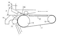
図2は、搬送ベルト17に対する方向変換されたシートSが導入される位置の構成を示す図であり、同図において、搬送ベルト17と搬送ローラ23とが位置するシートの入り口側には、給紙部SPから繰り出されたシートSを搬送ベルト17の平坦部と平行する水平方向に方向変換する方向変換ガイド部材24が設けられている。
方向変換ガイド部材24は、搬送ベルト17の駆動ローラ18に対峙して設けられているカウンタローラ25とこれに対向してシートSの搬送路を90度変換する変換搬送ガイド部材14とは別に設けられ、その位置は、変換搬送ガイド部材14により方向変換されたシートSの先端が駆動ローラ8の曲率により分離されやすい位置とされている。
この場合の曲率分離されやすい位置とは、カウンタローラ25により駆動ローラ18の周面に押し付けられて駆動ローラ18の周面に倣う形状に癖付けされたシートが自らの曲げ剛性による形状復元力によって反り返る位置に相当しており、図2に示す構成では、駆動ローラ18と搬送ローラ23との対峙位置よりもシートの移動方向後方に位置している。
【0021】
方向変換ガイド部材24には、シート先端が駆動ローラ18側から反り返って駆動ローラ18側から離れる位置に、シートが変換された方向、この場合には、垂直方向から水平方向にシートを指向させる角度(図2中、符号θで示す角度)を有する湾曲面あるいは傾斜面からなるガイド面24Aが設けられている。
湾曲面である場合にはシートを指向させる角度を有する面が一部にあることを意味している。
湾曲面である場合には、図2において二点鎖線で示すように、駆動ローラ18側から離れたシートの先端が湾曲面に沿って湾曲されながら指向させる角度の面に移動することになり、傾斜面の場合には、図示しないが、先端が突き当たるとそのままシートが折れ曲がり搬送ベルト17の平坦部に向けて指向されることになる。湾曲面は比較的厚さが厚く曲折しにくいシートに有効であり、傾斜面は突き当たることで折曲しやすい薄手のシートに有効である。
【0022】
本実施形態は以上のような構成であるから、給紙部SPから繰り出されたシートSは、搬送途中で垂直方向に方向変換され、再度垂直方向から水平方向、つまり、搬送ベルト17の平坦部と平行する方向に方向変換される。
搬送ベルト17の平坦部に向けて方向変換される位置では、搬送ベルト17の駆動ローラ18から先端が反り返ると、その先端が方向変換ガイド部24のガイド面24Aに進入することでその面に沿って移動し、図2中、二点鎖線で示すように、搬送ベルト17の平坦部に向けて指向されることになる。
【0023】
特に、シートSは先端が方向変換ガイド部24のガイド面24Aに進入すると、それ以降の部分も連続してガイド面24Aを通過することができるので、先端のみでなくそれ以外の部分が搬送ベルト17の平坦部に向けて指向される状態が維持される。この結果、搬送ベルト17による静電吸着によって平坦部ではシートが搬送ベルト17に密着することができ、搬送ベルト17の平坦部がその裏側に位置するガイド部材20によってインクヘッド15との対向間隔を規定されていることに順じてシートSもインクヘッド15との対向間隔を一定化される。これにより、インクヘッド15からのインクの吐出ポイントが不均一となることがなく、画質悪化が防止されることになる。
【0024】
【発明の効果】
請求項1および2記載に発明によれば、方向変換位置に、変換された方向にシートを指向させるガイド部を設け、特に請求項2記載の発明では、ガイド部が版胴ベルトを掛け回しているローラの外周囲に配置されて搬送ベルトの平坦部に向けてシートを指向させる角度を有する湾曲面若しくは傾斜面を有しているので、シートをその面に沿わせながら移動させる過程でシートを搬送ベルトの平坦部に指向させる状態を維持することができる。これにより、シート先端およびこれ以降の面がガイド部により平坦部に向けて指向される状態を維持されていることで搬送ベルトによる静電吸着されやすくな理、搬送ベルトの平面性に倣うことができる。
【0025】
請求項3および4記載の発明によれば、搬送ベルトの平坦部がインクヘッドに対向する位置に配置されているガイド部材上を搬送ベルトが移動することにより形成されるので、平坦部に向け指向されたシートは搬送ベルトの平面性に倣って移動することができる。これにより、ガイド部材がインクヘッドとの対向間隔を規定されている場合には、搬送ベルトの平坦部に倣うシートもインクヘッドとの対向間隔が規定され、対向間隔の変化によるインクの吐出ポイントずれなどの不具合を解消することができ、画質悪化を防止することが可能となる。
【図面の簡単な説明】
【図1】本発明の実施形態に係るシート搬送装置が適用される画像形成装置の一例を示す模式図である。
【図2】本発明の実施形態に係るシート搬送装置の要部構成を説明するための模式図である。
【符号の説明】
SP 給紙部
PP 印字処理部
EP 排紙部
100 インクジェット記録装置
13 変換ガイド部材
14 反転変換ガイド部材
15 インクヘッド
17 搬送ベルト
18 駆動ローラ
19 テンションローラ
22 排紙ローラ
23 搬送ローラ
24 方向変換ガイド部材
24A ガイド面
25 カウンタローラ
S シート[0001]
TECHNICAL FIELD OF THE INVENTION
The present invention relates to a sheet conveying apparatus and an ink jet recording apparatus, and more particularly, to a sheet conveying mechanism in an ink jet recording apparatus having a reversing path in a sheet conveying path to an image forming area.
[0002]
[Prior art]
As one of the image forming apparatuses, there is a printing apparatus that directly records an image on a conveyed sheet.
2. Related Art As a printing apparatus, an ink jet recording apparatus that prints an image by ejecting ink droplets to a sheet based on image information is known.
The ink jet recording apparatus includes an ink head that discharges ink droplets, and a conveyance path that feeds a sheet toward a printing area, which is an image forming area where the ink head and the sheet face each other, and discharges the sheet from the printing area. May be combined with a sheet conveying device.
On the other hand, the sheet transport path includes not only a path that moves in one direction such as a horizontal direction, but also a configuration in which the direction is changed vertically in the middle from the paper supply unit to the paper discharge unit to reverse and move the sheet. (For example, Patent Document 1).
[0003]
The reason for adopting such a configuration is to save the space of the apparatus.In this case, the paper feed tray and the paper output tray are provided in the vertical direction, and the sheet fed from the paper feed tray is moved in the vertical direction. By changing the direction, the image is reversed and moved to the print area. Further, after printing, a configuration is adopted in which the sheet is moved in the horizontal direction and discharged to a paper discharge tray.
[0004]
By the way, in the print area, it is important that the distance between the sheet and the ink head is accurately defined in order not to deteriorate the image quality. In other words, the interval between the ink head and the ink head is determined by the flatness of the sheet. Therefore, in the sheet conveyance structure, the sheet is suctioned with a negative pressure in the printing area and brought into close contact with the flat plate or the conveyance roller to make contact with the ink head. There has been proposed a configuration for defining an interval between the two (for example, Patent Document 1).
[0005]
As a configuration for negative pressure suction, a configuration has been proposed in which a transport belt is provided that is hung around a pair of rollers and a surface facing the ink head is extended in a horizontal direction, and a sheet is attracted to the transport belt and transported. (For example, Patent Document 2).
[0006]
Apart from negative pressure suction, as a configuration to obtain the flatness of the sheet, that is, a state without waviness and wrinkles, one of the pair of nipping rollers used to feed the sheet to the printing area is used as a sheet pressing roller It is also suggested that the sheet be extended in a state where the sheet is extended so that swelling and wrinkles are not generated by the pressing roller, or that the degree of swelling is detected and the printing process is not performed when the swelling state is higher than a predetermined swelling state. (For example, Patent Document 3).
[0007]
[Patent Document 1]
JP 2000-158637 A (each column of paragraphs “0016”, “0017”, and “0028”)
[Patent Document 2]
JP-A-2000-211762 (paragraph "0019" column, FIG. 2)
[Patent Document 3]
JP 2001-262459 A (each column of paragraphs “0083”, “0094”, and “0104”)
[0008]
[Problems to be solved by the invention]
As a sheet used for the printing process, not only a sheet having a relatively small thickness such as plain paper used for general copying but also, in an extreme case, a thick sheet such as glossy paper or a postcard can be a printing target. .
A sheet having a large thickness has a high bending rigidity and therefore has a strong shape restoring force when bent. When a sheet having such mechanical characteristics is moved along the above-described sheet conveyance path having the reversing path, the sheet recurs at the reversing portion due to the shape restoring force. For this reason, when the thick sheet folded back toward the flat portion of the transport belt is moved, the leading end is likely to bend back, so that it is difficult to be attracted to the flat portion of the transport belt.
In particular, when the sheet moving toward the flat portion of the conveyor belt is reoriented by the shape restoring force in the same direction as the roller on which the conveyor belt is wound when the direction is changed, the leading end of the sheet moves from the peripheral surface. Leave. Therefore, it is conceivable to prepare a counter roller or the like that presses against the peripheral surface. However, since the portion to be pressed is only the position facing the counter roller, the counter roller cannot be moved completely following the roller peripheral surface.
[0009]
In such a situation, the sheet cannot be guided to the flat portion of the transport belt, or even follow the flat portion. As a result, the facing distance between the ink head and the sheet is not constant, and the image quality deteriorates. Will not escape.
[0010]
SUMMARY OF THE INVENTION An object of the present invention is to solve the above-described conventional sheet conveyance device, particularly in consideration of the problem of conveying a stiff sheet when the conveyance path has a direction change, so that even a thick sheet can be conveyed to a conveyance belt. It is an object of the present invention to provide a sheet conveying apparatus and an ink jet recording apparatus having a configuration capable of improving the adhesiveness of the sheet and maintaining a constant distance between the sheet and the printing unit.
[0011]
[Means for Solving the Problems]
According to a first aspect of the present invention, there is provided a sheet transporting apparatus having a configuration in which a part of a transport path fed from a paper feeding unit is changed in direction, and a guide for directing the sheet in the converted direction to the direction changing position. It is characterized by having a part.
[0012]
According to a second aspect of the present invention, in addition to the first aspect of the present invention, when the guide portion uses a transport belt for electrostatically adsorbing the sheet, the guide portion is provided outside a roller around which the transport belt is wound. It is characterized by having a guide surface provided around the periphery and having a curved surface having an angle to direct the leading end of the sheet toward a flat portion formed on the transport belt.
[0013]
According to a third aspect of the present invention, there is provided a method of using the sheet conveying apparatus according to the first or second aspect in an ink jet recording apparatus.
[0014]
According to a fourth aspect of the present invention, in addition to the third aspect, the flat portion of the transport belt is formed by moving the transport belt on a guide member arranged at a position facing the ink head. It is characterized by being done.
[0015]
BEST MODE FOR CARRYING OUT THE INVENTION
Hereinafter, embodiments of the present invention will be described with reference to the drawings.
FIG. 1 is a diagram illustrating an ink jet recording apparatus to which a sheet conveying apparatus according to an embodiment of the present invention is applied. The ink
[0016]
In FIG. 1, the ink
In the sheet feeding unit SP, the
[0017]
The print processing unit PP that performs print processing on the sheet S fed from the paper supply unit SP includes an
[0018]
The print processing unit PP is provided with a structure for printing the sheet S facing the
The
The surface of the
[0019]
In one of the directions in which the sheet S moves across the flat portion of the
[0020]
FIG. 2 is a diagram illustrating a configuration of a position where the sheet S whose direction has been changed with respect to the
The direction
In this case, the position where the curvature is easily separated means that the sheet which is pressed against the peripheral surface of the driving
[0021]
The direction
In the case of a curved surface, it means that a surface having an angle for directing the sheet is partially present.
In the case of a curved surface, as shown by a two-dot chain line in FIG. 2, the leading end of the sheet away from the
[0022]
Since the present embodiment is configured as described above, the sheet S fed from the sheet feeding unit SP is changed in the vertical direction during the conveyance, and is again changed from the vertical direction to the horizontal direction, that is, the flat portion of the
At the position where the direction is changed toward the flat portion of the
[0023]
In particular, when the leading end of the sheet S enters the
[0024]
【The invention's effect】
According to the first and second aspects of the present invention, a guide portion for directing the sheet in the converted direction is provided at the direction conversion position. In the second aspect of the present invention, the guide portion wraps around the plate cylinder belt. It has a curved surface or an inclined surface that is disposed around the outer periphery of the roller and directs the sheet toward the flat portion of the conveyor belt, so that the sheet is moved in the process of moving the sheet along the surface. It is possible to maintain a state in which the transfer belt is directed to the flat portion. Accordingly, the state in which the leading end of the sheet and the subsequent surface are directed toward the flat portion by the guide portion is maintained, so that the sheet is easily electrostatically attracted by the transport belt, and the flatness of the transport belt is imitated. it can.
[0025]
According to the third and fourth aspects of the present invention, since the flat portion of the transport belt is formed by moving the transport belt on the guide member disposed at a position facing the ink head, the flat portion is directed toward the flat portion. The moved sheet can move following the flatness of the transport belt. Accordingly, when the guide member has a prescribed distance from the ink head, the sheet following the flat portion of the transport belt also has a prescribed distance from the ink head. And the like can be eliminated, and deterioration of image quality can be prevented.
[Brief description of the drawings]
FIG. 1 is a schematic diagram illustrating an example of an image forming apparatus to which a sheet conveying device according to an embodiment of the present disclosure is applied.
FIG. 2 is a schematic diagram for explaining a main configuration of a sheet conveying apparatus according to an embodiment of the present invention.
[Explanation of symbols]
SP paper feed unit PP print processing unit EP
Claims (4)
上記方向変換位置に、変換された方向に上記シートを指向させるガイド部を備えたことを特徴とするシート搬送装置。In a sheet conveying apparatus having a configuration in which a part of a conveying path fed from a sheet feeding unit is changed in direction,
A sheet conveying device, comprising: a guide unit for directing the sheet in the changed direction at the direction change position.
上記ガイド部は、上記シートを静電吸着する搬送ベルトを用いた場合に、該搬送ベルトが掛け回されているローラの外周囲に配置され、該搬送ベルトに形成される平坦部に向けて上記シート先端を指向させる角度を有する湾曲面若しくは傾斜面を備えたガイド面を有していることを特徴とするシート搬送装置。The sheet conveying device according to claim 1,
The guide section, when using a transport belt that electrostatically attracts the sheet, is disposed around the roller around which the transport belt is wound, and faces the flat portion formed on the transport belt. A sheet conveying device having a guide surface having a curved surface or an inclined surface having an angle for directing a leading end of a sheet.
上記搬送ベルトの平坦部は、インクヘッドに対向する位置に配置されているガイド部材上を該搬送ベルトが移動することにより形成されることを特徴とするインクジェット記録装置。The inkjet recording apparatus according to claim 3,
The ink jet recording apparatus according to claim 1, wherein the flat portion of the transport belt is formed by moving the transport belt on a guide member disposed at a position facing the ink head.
Priority Applications (1)
| Application Number | Priority Date | Filing Date | Title |
|---|---|---|---|
| JP2003003961A JP2004217331A (en) | 2003-01-10 | 2003-01-10 | Sheet conveying device and ink jet recording device |
Applications Claiming Priority (1)
| Application Number | Priority Date | Filing Date | Title |
|---|---|---|---|
| JP2003003961A JP2004217331A (en) | 2003-01-10 | 2003-01-10 | Sheet conveying device and ink jet recording device |
Publications (2)
| Publication Number | Publication Date |
|---|---|
| JP2004217331A true JP2004217331A (en) | 2004-08-05 |
| JP2004217331A5 JP2004217331A5 (en) | 2006-03-16 |
Family
ID=32895071
Family Applications (1)
| Application Number | Title | Priority Date | Filing Date |
|---|---|---|---|
| JP2003003961A Pending JP2004217331A (en) | 2003-01-10 | 2003-01-10 | Sheet conveying device and ink jet recording device |
Country Status (1)
| Country | Link |
|---|---|
| JP (1) | JP2004217331A (en) |
Cited By (4)
| Publication number | Priority date | Publication date | Assignee | Title |
|---|---|---|---|---|
| JP2006096527A (en) * | 2004-09-29 | 2006-04-13 | Brother Ind Ltd | Recording medium carrying device, image forming device and cartridge |
| US7555238B2 (en) | 2004-09-29 | 2009-06-30 | Brother Kogyo Kabushiki Kaisha | Image-forming device and angularly shifted belt unit |
| US7586508B2 (en) | 2004-06-22 | 2009-09-08 | Brother Kogyo Kabushiki Kaisha | Image-forming device with scanner unit |
| JP2011111300A (en) * | 2009-11-27 | 2011-06-09 | Canon Inc | Conveying mechanism and recording device including the same |
-
2003
- 2003-01-10 JP JP2003003961A patent/JP2004217331A/en active Pending
Cited By (8)
| Publication number | Priority date | Publication date | Assignee | Title |
|---|---|---|---|---|
| US7586508B2 (en) | 2004-06-22 | 2009-09-08 | Brother Kogyo Kabushiki Kaisha | Image-forming device with scanner unit |
| US7804515B2 (en) | 2004-06-22 | 2010-09-28 | Brother Kogyo Kabushiki Kaisha | Image-forming device with scanner unit |
| JP2006096527A (en) * | 2004-09-29 | 2006-04-13 | Brother Ind Ltd | Recording medium carrying device, image forming device and cartridge |
| US7506866B2 (en) | 2004-09-29 | 2009-03-24 | Brother Kogyo Kabushiki Kaisha | Recording medium conveying device, image forming apparatus and cartridge |
| US7555238B2 (en) | 2004-09-29 | 2009-06-30 | Brother Kogyo Kabushiki Kaisha | Image-forming device and angularly shifted belt unit |
| US7620344B2 (en) | 2004-09-29 | 2009-11-17 | Brother Kogyo Kabushiki Kaisha | Image forming apparatus, drawable cartridge, and recording medium accommodating cartridge |
| US7862030B2 (en) | 2004-09-29 | 2011-01-04 | Brother Kogyo Kabushiki Kaisha | Recording medium conveying device, image forming apparatus and cartridge |
| JP2011111300A (en) * | 2009-11-27 | 2011-06-09 | Canon Inc | Conveying mechanism and recording device including the same |
Similar Documents
| Publication | Publication Date | Title |
|---|---|---|
| JP2004262204A (en) | Inkjet printer | |
| JP6790786B2 (en) | Sheet transfer device and image forming device equipped with it | |
| JP6213421B2 (en) | Recording medium decurling device and image forming apparatus having the same | |
| JP5143456B2 (en) | Paper transport device and ink jet recording apparatus using the same | |
| JP3919539B2 (en) | Inkjet recording device | |
| JP2004217331A (en) | Sheet conveying device and ink jet recording device | |
| JP2006264828A (en) | Image recording device | |
| US9636930B1 (en) | Transport with media hold down for inkjet printers | |
| JP5617664B2 (en) | Recording medium conveying apparatus and image forming apparatus | |
| JP2011046519A (en) | Paper carrying device and image forming device | |
| JP3694006B2 (en) | Inkjet printer | |
| JP2002326755A (en) | Recording paper delivering mechanism for image forming device | |
| JP2007254122A (en) | Pair of carrying rollers and recording device using the pair of carrying rollers | |
| JP2002067416A (en) | Ink jet recorder | |
| JP3125442U (en) | Printing device | |
| JP2001341886A (en) | Recording device | |
| JP2004217332A (en) | Sheet conveying device and ink jet recording device | |
| JP2002211056A (en) | Image forming apparatus | |
| US10336564B2 (en) | Medium transporting apparatus and recording apparatus | |
| JPH08301497A (en) | Paper guide device in image forming device | |
| JP2004182440A (en) | Image forming device and recording head | |
| JP2012051128A (en) | Inkjet printing apparatus | |
| JPH10193590A (en) | Ink jet printer | |
| JPH11227978A (en) | Sheet processing device and recording device | |
| JP2003118911A (en) | Sheet discharge mechanism |
Legal Events
| Date | Code | Title | Description |
|---|---|---|---|
| A621 | Written request for application examination |
Effective date: 20050627 Free format text: JAPANESE INTERMEDIATE CODE: A621 |
|
| A521 | Written amendment |
Free format text: JAPANESE INTERMEDIATE CODE: A523 Effective date: 20060131 |
|
| A977 | Report on retrieval |
Free format text: JAPANESE INTERMEDIATE CODE: A971007 Effective date: 20070521 |
|
| A131 | Notification of reasons for refusal |
Effective date: 20070612 Free format text: JAPANESE INTERMEDIATE CODE: A131 |
|
| A521 | Written amendment |
Effective date: 20070810 Free format text: JAPANESE INTERMEDIATE CODE: A523 |
|
| A131 | Notification of reasons for refusal |
Effective date: 20071113 Free format text: JAPANESE INTERMEDIATE CODE: A131 |
|
| A521 | Written amendment |
Free format text: JAPANESE INTERMEDIATE CODE: A523 Effective date: 20080115 |
|
| A02 | Decision of refusal |
Effective date: 20080318 Free format text: JAPANESE INTERMEDIATE CODE: A02 |