JP2004216523A - Method of manufacturing non-flexible foam resin chip - Google Patents
Method of manufacturing non-flexible foam resin chip Download PDFInfo
- Publication number
- JP2004216523A JP2004216523A JP2003008472A JP2003008472A JP2004216523A JP 2004216523 A JP2004216523 A JP 2004216523A JP 2003008472 A JP2003008472 A JP 2003008472A JP 2003008472 A JP2003008472 A JP 2003008472A JP 2004216523 A JP2004216523 A JP 2004216523A
- Authority
- JP
- Japan
- Prior art keywords
- cutter
- rotary plate
- rotating plate
- sample
- chip
- Prior art date
- Legal status (The legal status is an assumption and is not a legal conclusion. Google has not performed a legal analysis and makes no representation as to the accuracy of the status listed.)
- Pending
Links
Images


Landscapes
- Cultivation Of Plants (AREA)
- Details Of Cutting Devices (AREA)
- Nonmetal Cutting Devices (AREA)
Abstract
Description
【0001】
【発明の属する技術分野】
本発明は、育苗などに使用される非可撓性発泡樹脂製チップの製造方法に関する。
【0002】
【従来の技術】
従来、例えばウレタン樹脂からなる可撓性発泡体等をチップ状にするには、樹脂発泡体を上下のロールで挟み込んで動かないように固定した後、綿打ち機のようなロールに付いた鉤状のピンでかきむしってゆき、出口に行くまでにスクリーニングして、篩より大きなものはまた供給口へ戻し、一定サイズよりも小さいチップとして製造されていた。
【0003】
また、別の方式として、上述の様に樹脂発泡体を固定した後、プラスチック粉砕用の段違い回転刃のついた装置を用いて引きちぎってゆき、出口に行くまでにスクリーニングして、篩より大きなものはまた供給口へ戻し、一定サイズよりも小さいチップとして製造されていた。
【0004】
更に、角状のチップを得るには、カッター等で手作業により行なっていた。
【0005】
なお、従来、非可撓性発泡樹脂試料を定寸かつ定形状の角形状のチップに切断する技術は、全く知られていなかった。
【0006】
【特許文献】
なし
【0007】
【発明が解決しようとする課題】
しかし、従来技術によれば、次のような問題点を有していた。
樹脂発泡体が非可撓性発泡体の場合、ロールの回転に触れるだけで発泡体表面がくずれてしまい、更にロールで樹脂発泡体を固定しようとした時点で発泡体全体がくずれてしまう。更に、ロールで樹脂発泡体をうまく挟みこめても、樹脂発泡体を引きちぎろうとした際に粉々になってしまい、不定形な小片がわずかな量と大量の粉ができあがるだけで、一定の形状・寸法を有し、チップとして用いることができるようなものは製造することはできなかった。更には、手作業の場合、角形状はできるものの、大きさが不均一であるとともに、多大な労力と時間を要していた。
【0008】
本発明はこうした事情を考慮してなされたもので、搬送手段により非可撓性発泡樹脂製試料を回転板に取り付けられたカッター部に供給し、供給された試料をカッター部で定寸かつ定形状の角形状のチップに切断することにより、大きさが均一な角形状のチップを簡単かつ短時間に製造することが可能な非可撓性発泡樹脂製チップの製造方法を提供することを目的とする。
【0009】
【課題を解決するための手段】
本発明は、角形状のチップを排出するための開口部を有し、かつカッター部を備えた回転板と、少なくともこの回転板のカッター部に対して非可撓性発泡樹脂製試料を供給する投入口及び搬送手段と、前記回転板,搬送手段を夫々駆動する駆動手段とを具備し、前記回転板のカッター部は投入口と回転板との間にあって、回転板に取り付けられ、カッター部のナイフ刃は回転板と略平行であるように回転板に取り付けられ、複数のスリット歯は前記開口部においてナイフ刃と直角に交差するように配置されるカッター装置を用いて、非可撓性発泡樹脂製試料から角形状のチップを製造する方法において、
前記搬送手段により前記試料を前記投入口からカッター部に供給し、供給された試料を前記カッター部で定寸かつ定形状の角形状のチップに切断した後、前記チップを回転板の裏面側に送り出すことを特徴とする非可撓性発泡樹脂製チップの製造方法である。
【0010】
【発明の実施の形態】
以下、本発明に係る非可撓性発泡樹脂製チップの製造方法について更に詳しく説明する。ここで、前記非可撓性発泡樹脂とは、顕著なたわみ性、回復性を有さない性質をもつ発泡樹脂を指し、硬質・半硬質発泡ウレタン樹脂、発泡フェノール樹脂等が挙げられる。
【0011】
本発明において、回転板とカッター部のナイフ刃間の距離、スリット歯の間隔、及びカッター部に供給する非可撓性発泡樹脂製試料の高さは任意に変えることができ、これらを変えることによりチップの寸法を自由に調整することができる。従って、前記ナイフ刃、スリット歯は回転板に対して取り外しできるような構成にすることが好ましい。
【0012】
また、前記カッター部は、回転板の中心と円周上の点を直線で結ぶ線上に少なくとも1つ以上配置されていることが好ましい。ここで、前記回転板とカッター部のナイフ刃間の距離をL、前記スリット歯の間隔をDとしたとき、距離L及び/叉は間隔Dが異なるサイズを有した2種類以上のカッター部を配置することが好ましい。このようにすることにより、2種類以上のサイズの異なるチップを1回の運転で製造することができる。
【0013】
前記距離Lは、回転板とナイフ刃間に介在させるスペーサーの厚みにより自由に調整することができる(図2(C)参照)。前記スリット歯は、スリット歯フレームと溶接あるいは十分な長さを持って差し込むことにより一体化してある(図2(B)参照)。
【0014】
本発明において、前記回転板及び搬送手段はモータ等の駆動手段により駆動することができる。また、搬送手段としては、例えば駆動用ローラ及び従動用ローラに懸架されたコンベアベルトが挙げられるが、これに限定されず、複数のローラ等でもよい。
【0015】
本発明において、非可撓性発泡樹脂製試料をカッター部でカットする際、小さなチップ片及び若干のカット粉が発生するので、これらが装置内に滞まらないように帯電防止対策を施すことが好ましい。
【0016】
このような装置としては、食品用のフードスライサーの歯部にスリット歯を取り付けたものを好適に使用することができる。前記フードスライサーの一例としては、株式会社榎村鐵工所のデジタル式フードスライサー(商品名:ECD−201型)が挙げられる。
【0017】
【実施例】
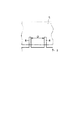
以下、本発明の一実施例について図1〜図3を参照して説明する。ここで、図1は本発明に係る非可撓性発泡樹脂製チップの製造方法に使用される製造装置の説明図であり、図1(A)は該製造装置の概略を示す全体図、図1(B)は同製造装置の回転板の平面図を示す。図1(C)はカバー部分1aの平面図を示す。また、図2はカッター部の要部を拡大した説明図であり、図2(A)は回転板のカッター部を表面側(投入口側)から見た図、図2(B)はカッター部を裏面側(排出側)から見た図、図2(C)はカッター部の要部の断面図を示す。更に、図3は、図1の製造装置におけるカッター部のスリット歯の説明図を示す。但し、下記実施例に記載された材料等は一例を示すもので、本発明はこれらの記載に限定されるものではない。
【0018】
図1において、符番1は、下部にチップ排出口1’を有した、カバー部分1a,1bからなるカバーを示す。このカバー1によってカッター部2を備えた回転板3が覆われている。前記カッター部2が取り付けられている回転板3には、カットした試料を排出する開口部4が形成されている。前記カッター部2は、図2に示すように、回転板3の表面側にネジ11により取り付けられ,回転板と略平行であるように取り付けられたナイフ刃5と、このナイフ刃5に対して直角に交差するとともに互に離間するように配置された複数のスリット歯6とから構成されている。前記ネジ11は、ボルト11aとナット11bよりなる。
【0019】
前記スリット歯6は、回転板3にネジにより取り付けられている。ここで、ナイフ5の先端5aとスリット歯6の先端6aは、接している。この理由は、先端5a,6aのいずれかが先に試料に当たるようになっていても良いが、必ず一部で接していないと試料の一部がつながった状態で排出されてしまうので、これを回避するためである。図2から明らかのように、スリット歯6は、ネジ7を用いて回転板3に固定されたスリット歯フレーム8に支持されている。ここで、ネジ7は、ボルト7aとナット7bよりなる。また、前記開口部4には、チップが排出口からスムーズに落ちるように排出ガイド10が設けられている。
【0020】
前記カッター部2は、図1(B)、図2(A)、(B)に示すように、回転板3の中心と円周上の点を結ぶ線上に配置されている。前記回転板3の中央部には、回転軸12を介して図示しない第1のモータ(駆動手段)が連結され、該モータにより回転板3が例えば矢印Aのように回転するようになっている。また、前記回転板3の近くには、駆動用ローラ13、従動用ローラ14に懸架されたループ状のコンベアベルト(搬送手段)15が配置されている。前記駆動用ローラ13には、回転軸12を介してモータ(駆動手段)16が連結され、該モータ16により駆動用ローラ13が駆動してコンベアベルト15を矢印B方向に搬送するようになっている。また、投入口17より、回転板3に取り付けられたカッター部2に確実に試料が搬送されるように、コンベアベルト15の上方には上部押え用ベルト18が配置されている。このベルト18は、駆動モータを有さず、試料を確実に保持するために配置してある。
【0021】
図1〜図3の製造装置を用いてチップを製造する場合は、次のように行う。即ち、図示しないモータで回転板3を矢印A方向に回転させながら、モータ16により駆動用ローラ13を駆動させてコンベアベルト15を駆動させ、コンベアベルト15上の非可撓性発泡樹脂製試料19を矢印B方向に搬送させることにより行う。試料19は上部押え用ベルト18により確実に固定され、投入口17よりカッター部2に試料19の先端が回転板3に突き当るまで搬送される。そして、試料19は、カッター部2のナイフ刃5とスリット歯6により、回転板3が半周する毎に角形状のチップ20に切断される。ここで、一方のナイフ刃5は試料19の搬送方向に対して垂直となるようにカットし、他方のスリット歯6は試料19の搬送方向と平行となるようにカットする。また、前記回転板3とナイフ刃5間の距離をL、スリット歯6の間隔をD、カッター部2に供給する試料19の高さをHとしたとき、前記距離L,間隔D及び高さHを任意に調整することにより、角形状のチップの形状を任意に変えることができる。切断されたチップ20は、回転板3の開口部4から回転板3の裏面側に排出されて、カバー1の排出口1’より取り出される。
【0022】
このように、上記実施例による製造方法によれば、回転板3のカッター部2に搬送される非可撓性発泡樹脂製試料19を、試料19に対して垂直なナイフ刃5及びスリット歯6からなるカッター部2で角形状にカットすることにより、粉々にならずに定寸かつ定形状の角形状のチップ20を連続的に製造することができる。また、機械化によりチップ20の製造時間を著しく短縮することができる。
【0023】
なお、上記実施例では、カッター部が回転板に2箇所設けられている場合について述べたが、これに限定されない。
【0024】
また、上記実施例では、排出ガイドとスペーサーが一体的になっている場合について述べたが、これに限らず、回転板に別々に取り付けられていてもよいし、一体に削り出されたものを使用してもよい。なお、排出ガイドはチップが排出口からスムーズに落ちるように設けたものであるが、必ずしも設ける必要はない。
【0025】
更に、上記実施例では、ナイフ刃、スリット歯フレームについてネジ止めした場合について述べたが、これに限らず、溶接等、従来公知の接合手段を用いることもできるし、スリット歯をナイフ刃に接合させたものを用いてもよい。
【0026】
【発明の効果】
以上詳述したように本発明によれば、搬送手段により非可撓性発泡樹脂製試料をカッター部に供給し、供給された試料をカッター部で定寸かつ定形状の角形状のチップに切断することにより、一定の形状・寸法を有し、育苗等に用いることができる角形状のチップを簡単かつ短時間に製造することが可能な非可撓性発泡樹脂製チップの製造方法を提供できる。
【図面の簡単な説明】
【図1】本発明に係る非可撓性発泡樹脂製チップの製造方法に使用される製造装置の説明図。
【図2】図1の製造装置におけるカッター部の要部を拡大して示す説明図。
【図3】図1の製造装置におけるカッター部のスリット歯の説明図。
【符号の説明】
2…カッター部、 3…回転板、 4…開口部、
5…ナイフ刃、 5a,6a…先端、 6…スリット歯、
7,11…ネジ、 8…スリット歯フレーム、 10…排出ガイド、
12…回転軸、 13…駆動用ローラ、 14…従動用ローラ、
15…コンベアベルト、 16…モータ 17…投入口、
18…上部押え用ベルト、 19…非可撓性発泡樹脂製試料、 20…チップ。[0001]
TECHNICAL FIELD OF THE INVENTION
The present invention relates to a method for producing a non-flexible foamed resin chip used for raising seedlings and the like.
[0002]
[Prior art]
Conventionally, for example, in order to form a flexible foam made of urethane resin into a chip shape, a resin foam is sandwiched between upper and lower rolls, fixed so as not to move, and a hook-like shape attached to a roll such as a cotton hammer. After being squeezed with the pins and screening before going to the outlet, those larger than the sieve were returned to the supply port again and manufactured as chips smaller than a certain size.
[0003]
As another method, after fixing the resin foam as described above, tearing it off using a device with a stepped rotary blade for crushing plastics, screening by the time it goes to the outlet, a screen larger than the sieve Was returned to the supply port and was manufactured as chips smaller than a certain size.
[0004]
Further, in order to obtain a horn-shaped chip, it is manually performed with a cutter or the like.
[0005]
Heretofore, no technique has been known for cutting a non-flexible foamed resin sample into fixed-size and fixed-size square chips.
[0006]
[Patent Document]
None [0007]
[Problems to be solved by the invention]
However, the prior art has the following problems.
When the resin foam is a non-flexible foam, the foam surface is destroyed only by touching the rotation of the roll, and further, when the resin foam is fixed by the roll, the entire foam collapses. Furthermore, even if the resin foam is properly sandwiched between the rolls, it will be broken when trying to tear the resin foam, and only a small amount of irregular shaped pieces and a large amount of powder will be formed,・ Thing having dimensions and being usable as a chip could not be manufactured. Furthermore, in the case of manual work, although a square shape can be formed, the size is not uniform and a great deal of labor and time are required.
[0008]
The present invention has been made in view of such circumstances, and a non-flexible foamed resin sample is supplied to a cutter unit attached to a rotating plate by a transport unit, and the supplied sample is measured and fixed by the cutter unit. An object of the present invention is to provide a method for manufacturing a non-flexible foamed resin chip, which can cut a square chip having a uniform size easily and in a short time by cutting the chip into a square chip having a shape. And
[0009]
[Means for Solving the Problems]
The present invention provides a rotating plate having an opening for discharging a rectangular chip and having a cutter portion, and supplying a non-flexible foamed resin sample to at least the cutter portion of the rotating plate. An input port and a transport unit; and a driving unit for driving the rotary plate and the transport unit, respectively. A cutter unit of the rotary plate is located between the input port and the rotary plate, and is attached to the rotary plate. The knife blade is attached to the rotating plate so as to be substantially parallel to the rotating plate, and a plurality of slit teeth are formed by using a cutter device arranged to intersect the knife blade at right angles to the knife blade at the opening. In a method of manufacturing a square chip from a resin sample,
The sample is supplied to the cutter unit from the input port by the transfer unit, and the supplied sample is cut into fixed-size and fixed-size square chips by the cutter unit. This is a method for producing a non-flexible foamed resin chip, which is characterized in that it is sent out.
[0010]
BEST MODE FOR CARRYING OUT THE INVENTION
Hereinafter, the method for producing a non-flexible foamed resin chip according to the present invention will be described in more detail. Here, the non-flexible foamed resin refers to a foamed resin having a property having no remarkable flexibility and recoverability, and examples thereof include a hard / semi-hard foamed urethane resin and a foamed phenol resin.
[0011]
In the present invention, the distance between the rotating plate and the knife blade of the cutter unit, the interval between the slit teeth, and the height of the non-flexible foamed resin sample supplied to the cutter unit can be arbitrarily changed. Thereby, the dimensions of the chip can be freely adjusted. Therefore, it is preferable that the knife blade and the slit teeth are configured to be detachable from the rotating plate.
[0012]
Further, it is preferable that at least one cutter unit is disposed on a line connecting the center of the rotary plate and a point on the circumference with a straight line. Here, when the distance between the rotary plate and the knife blade of the cutter unit is L and the interval between the slit teeth is D, two or more types of cutter units having different sizes of the distance L and / or the interval D are used. It is preferable to arrange them. In this manner, two or more types of chips having different sizes can be manufactured in one operation.
[0013]
The distance L can be freely adjusted by the thickness of the spacer interposed between the rotating plate and the knife blade (see FIG. 2C). The slit teeth are integrated with the slit tooth frame by welding or by inserting with a sufficient length (see FIG. 2B).
[0014]
In the present invention, the rotating plate and the transporting means can be driven by a driving means such as a motor. In addition, examples of the transport unit include a conveyor belt suspended by a driving roller and a driven roller, but are not limited thereto, and may include a plurality of rollers.
[0015]
In the present invention, when a non-flexible foamed resin sample is cut by the cutter unit, small chip pieces and a small amount of cut powder are generated. Therefore, antistatic measures should be taken so that these pieces do not stay in the apparatus. Is preferred.
[0016]
As such a device, a food slicer for food, in which slit teeth are attached to the teeth, can be suitably used. As an example of the food slicer, there is a digital food slicer (trade name: ECD-201 type) manufactured by Enomura Corporation.
[0017]
【Example】
Hereinafter, an embodiment of the present invention will be described with reference to FIGS. Here, FIG. 1 is an explanatory view of a manufacturing apparatus used for a method of manufacturing a non-flexible foamed resin chip according to the present invention, and FIG. 1 (A) is an overall view schematically showing the manufacturing apparatus. 1B shows a plan view of a rotating plate of the manufacturing apparatus. FIG. 1C shows a plan view of the
[0018]
In FIG. 1, reference numeral 1 denotes a cover including
[0019]
The
[0020]
As shown in FIGS. 1B, 2A and 2B, the
[0021]
When a chip is manufactured by using the manufacturing apparatus shown in FIGS. 1 to 3, the operation is performed as follows. That is, while rotating the
[0022]
As described above, according to the manufacturing method of the above-described embodiment, the non-flexible foamed resin sample 19 conveyed to the
[0023]
In the above embodiment, the case where the cutter unit is provided at two places on the rotary plate has been described, but the present invention is not limited to this.
[0024]
Further, in the above-described embodiment, the case where the discharge guide and the spacer are integrated is described. However, the present invention is not limited to this, and the discharge guide and the spacer may be separately attached to the rotating plate or may be integrally cut out. May be used. Although the discharge guide is provided so that the chips fall smoothly from the discharge port, it is not always necessary to provide the discharge guide.
[0025]
Furthermore, in the above-described embodiment, the case where the knife blade and the slit tooth frame are screwed has been described. However, the present invention is not limited to this, and a conventionally known joining means such as welding may be used, or the slit tooth may be joined to the knife blade. You may use what was made.
[0026]
【The invention's effect】
As described above in detail, according to the present invention, a non-flexible foamed resin sample is supplied to the cutter unit by the transport unit, and the supplied sample is cut into fixed-size and fixed-shaped square chips by the cutter unit. By doing so, it is possible to provide a method for manufacturing a non-flexible foamed resin chip capable of easily and in a short time manufacturing a square chip having a certain shape and dimensions and usable for raising seedlings. .
[Brief description of the drawings]
FIG. 1 is an explanatory view of a manufacturing apparatus used for a method of manufacturing a non-flexible foamed resin chip according to the present invention.
FIG. 2 is an explanatory diagram showing an enlarged main part of a cutter unit in the manufacturing apparatus of FIG. 1;
FIG. 3 is an explanatory view of slit teeth of a cutter unit in the manufacturing apparatus of FIG.
[Explanation of symbols]
2 ... cutter part, 3 ... rotating plate, 4 ... opening,
5: knife blade, 5a, 6a: tip, 6: slit tooth,
7, 11 ... screw, 8 ... slit tooth frame, 10 ... discharge guide,
12: rotating shaft, 13: driving roller, 14: driven roller,
15 ... Conveyer belt, 16 ... Motor 17 ... Inlet,
18: Upper holding belt, 19: Non-flexible foam resin sample, 20: Chip.
Claims (4)
前記回転板のカッター部は投入口と回転板との間にあって、回転板に取り付けられ、カッター部のナイフ刃は回転板と略平行であるように回転板に取り付けられ、複数のスリット歯は前記開口部においてナイフ刃と直角に交差するように配置されるカッター装置を用いて、非可撓性発泡樹脂製試料から角形状のチップを製造する方法において、
前記搬送手段により前記試料を前記投入口からカッター部に供給し、供給された試料を前記カッター部で定寸かつ定形状の角形状のチップに切断した後、前記チップを回転板の裏面側に送り出すことを特徴とする非可撓性発泡樹脂製チップの製造方法。A rotary plate having an opening for discharging angular chips and having a cutter portion, and an inlet and a transport for supplying a non-flexible foamed resin sample to at least the cutter portion of the rotary plate Means, and driving means for driving the rotating plate and the transport means, respectively.
The cutter portion of the rotating plate is located between the input port and the rotating plate and is attached to the rotating plate, and the knife blade of the cutter portion is attached to the rotating plate so as to be substantially parallel to the rotating plate. In a method of manufacturing a square chip from a non-flexible foamed resin sample using a cutter device arranged to intersect the knife blade at a right angle at the opening,
The sample is supplied to the cutter unit from the input port by the transfer unit, and the supplied sample is cut into fixed-size and fixed-size square chips by the cutter unit. A method for producing a non-flexible foamed resin chip, comprising:
Priority Applications (1)
| Application Number | Priority Date | Filing Date | Title |
|---|---|---|---|
| JP2003008472A JP2004216523A (en) | 2003-01-16 | 2003-01-16 | Method of manufacturing non-flexible foam resin chip |
Applications Claiming Priority (1)
| Application Number | Priority Date | Filing Date | Title |
|---|---|---|---|
| JP2003008472A JP2004216523A (en) | 2003-01-16 | 2003-01-16 | Method of manufacturing non-flexible foam resin chip |
Publications (2)
| Publication Number | Publication Date |
|---|---|
| JP2004216523A true JP2004216523A (en) | 2004-08-05 |
| JP2004216523A5 JP2004216523A5 (en) | 2006-03-02 |
Family
ID=32898256
Family Applications (1)
| Application Number | Title | Priority Date | Filing Date |
|---|---|---|---|
| JP2003008472A Pending JP2004216523A (en) | 2003-01-16 | 2003-01-16 | Method of manufacturing non-flexible foam resin chip |
Country Status (1)
| Country | Link |
|---|---|
| JP (1) | JP2004216523A (en) |
Cited By (1)
| Publication number | Priority date | Publication date | Assignee | Title |
|---|---|---|---|---|
| CN107389413A (en) * | 2017-09-14 | 2017-11-24 | 西安科技大学 | A kind of laboratory rigid foam sampling machine |
-
2003
- 2003-01-16 JP JP2003008472A patent/JP2004216523A/en active Pending
Cited By (2)
| Publication number | Priority date | Publication date | Assignee | Title |
|---|---|---|---|---|
| CN107389413A (en) * | 2017-09-14 | 2017-11-24 | 西安科技大学 | A kind of laboratory rigid foam sampling machine |
| CN107389413B (en) * | 2017-09-14 | 2023-02-24 | 西安科技大学 | Laboratory rigid foam plastic sampling machine |
Similar Documents
| Publication | Publication Date | Title |
|---|---|---|
| US6695240B2 (en) | Shredding apparatus | |
| KR101963114B1 (en) | The cutting machine using centrifugal forec | |
| JP2011255561A (en) | Apparatus for producing sawdust | |
| JP2004216523A (en) | Method of manufacturing non-flexible foam resin chip | |
| JP2006271241A (en) | Screw transport structure | |
| JP3045163U (en) | Board shearing / crushing equipment with surface material | |
| JP2004290792A (en) | Crushing and separating unit | |
| JP2003126718A (en) | Crusher processor | |
| CN219445223U (en) | Rotary hardwood medicine cutting machine | |
| JP2000342160A (en) | Device for fixed quantity division and discharge of bread dough | |
| JPS582208Y2 (en) | Discarded straw processing device in threshing machine | |
| KR200203287Y1 (en) | Multiple cutting apparatus for raw squid | |
| CN207140138U (en) | A kind of rubber pulverizing equipment | |
| CN211160059U (en) | Straight sword cuts up screening plant | |
| CN206678051U (en) | A kind of Chinese medicinal material slicing device | |
| JPS6116081Y2 (en) | ||
| CN219601800U (en) | All-in-one is smashed to useless fungus stick of domestic fungus taking off bag | |
| JP2000317336A (en) | Crushing treatment apparatus of pet bottle, used paper or the like | |
| CN112107014A (en) | Preparation device for meat and bone meal and using method thereof | |
| JPH10218335A (en) | Selecting device for granular material | |
| CN219543314U (en) | Quantitative slicing device for traditional Chinese medicinal materials | |
| JP4817034B2 (en) | Compressed and consolidated feed crusher | |
| JP2004026207A (en) | Bag scrapping machine | |
| CN215611913U (en) | Spiral feeding device for foam box | |
| CN211491841U (en) | Cut sieve device of medicinal slicer |
Legal Events
| Date | Code | Title | Description |
|---|---|---|---|
| A521 | Written amendment |
Free format text: JAPANESE INTERMEDIATE CODE: A523 Effective date: 20060113 |
|
| A621 | Written request for application examination |
Free format text: JAPANESE INTERMEDIATE CODE: A621 Effective date: 20060113 |
|
| A977 | Report on retrieval |
Free format text: JAPANESE INTERMEDIATE CODE: A971007 Effective date: 20080115 |
|
| A131 | Notification of reasons for refusal |
Free format text: JAPANESE INTERMEDIATE CODE: A131 Effective date: 20080122 |
|
| A521 | Written amendment |
Free format text: JAPANESE INTERMEDIATE CODE: A523 Effective date: 20080321 |
|
| A131 | Notification of reasons for refusal |
Free format text: JAPANESE INTERMEDIATE CODE: A131 Effective date: 20090512 |
|
| A521 | Written amendment |
Free format text: JAPANESE INTERMEDIATE CODE: A523 Effective date: 20090710 |
|
| A02 | Decision of refusal |
Free format text: JAPANESE INTERMEDIATE CODE: A02 Effective date: 20100202 |