【0001】
【発明の属する技術分野】
本発明は、日常使用する傘に関するものである。
【0002】
【従来の技術】
従来の一般的な傘は、片手を完全にふさがれてしまうという欠点があった。この欠点を軽減しようとする従来の技術は、紐やパイプなどを使い、首や肩に傘をかける装置を付けるというものである。(たとえば、実公平5−68318、特公平10−33223、特公2000−41824、特公2002−78517)。
【0003】
【発明が解決しようとする課題】
上記にも述べたとおり、従来の一般的な傘は、片手が完全にふさがれてしまうという欠点があった。この欠点を軽減しようと考案された従来の技術も、日常持ち歩くには大げさすぎる装置であったり、手を離せるほどの安定性を持たなかったりするという問題点があった。
【0004】
本発明は、閉じて持ち歩く際にあまり邪魔にならない形の、片手で操作できる、使用時には一時的にでも手を離せるほどの安定性をもつ傘を提供することを目的としている。
【0005】
【課題を解決するための手段】
上記目的を達成するために、本発明の傘においては、内蔵引きバネを介して肩掛けフックと一体化させたスライダーと、流線形プッシュボタンと一体化した下はじきを、ガイドレールを成型したロッドに取り付け、押しバネを付けたロックと回転用ねじりバネ並びにキャップをグリップに取り付け、前記グリップを前記ロッドに固着させたものである。
【0006】
内蔵引きバネを介して肩掛けフックとスライダーを一体化させるのは、使用者の肩の厚さに合わせて伸縮させフィットさせるためである。
【0007】
また、スライダーはロッドの外周を利用して肩掛けフックを移動させるという目的と、肩掛けフックの支点になるという目的を合わせ持っている。ロッドの外周を移動するのであるから、スライダーの中心にはロッドを通すための空洞がなければならない。
【0008】
当然ながら上記の空洞の口径はロッドの外周の直径よりわずかに大きくするわけである。空洞の口径とロッド外周の直径の差の程度により、移動する際にどの程度の抵抗が生じるかが決まる。差が小さすぎれば抵抗が大きすぎてフックの移動が困難になり、逆に差が大きすぎるとスライダーがロッドのガイドレールから外れてしまう可能性が高くなる。
【0009】
ロッドにガイドレールを成型するのは、スライダーの移動領域を制御するためである。すなわち、ロッドの中間点付近で肩掛けフックを止めるためでもあり、また傘を閉じる際には邪魔にならない収納位置まで移動させるためでもある。ロッドの中間付近で止めるのは、この位置が最も安定性をもたらす支点になるからである。また、邪魔にならない収納位置とは、Jの字形のグリップと組み合わさって0の字を形成するような位置であろう。そこで、少なくとも下はじきを越えて双方向に移動できる仕組みが必要になる。
【0010】
それを可能にするのが、流線形プッシュボタンである。すなわち、プッシュボタンを流線形にすることにより、スライダーの通過の際には、通過自体の力によってプッシュボタン及びそれと一体の下はじきの露出部がロッド内にほぼ完全に埋没し、通過が終わると再び元の位置にもどるというわけである。
【0011】
また、ロッドは、上記したようにガイドレールを成形するのであるから、一般の傘に用いられているような材質と厚さでは強度に問題が生じる可能性が高い。それゆえ、軽くて強い材質で、ある程度厚さのあるロッドを採用しなければならない。おそらくアルミの一体成型加工などが適しているものと思われる。
【0012】
さらに、収納時には邪魔にならず、使用開始時には片手で操作できるという2つの要求を満たすために、スライダーをグリップのすぐ上で180度回転させるという手段を使う。そのために、先端を露出させた回転用ねじりバネとキャップ、ロッドの開口部、さらにはロック機構が必要なのである。
【0013】
【発明の実施の形態】
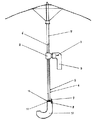
図1において、内蔵引きバネ1を介して肩掛けフック3と一体化させたスライダー2と、流線形プッシュボタン4と一体化した下はじき5を、ガイドレール6を有するロッド7に取り付け、押しバネ8を付けたロック9と回転用ねじりバネ10並びにキャップ11をグリップ12に取り付け、前記グリップを前記ロッドに固着させる。
【0014】
図2は、上記におけるキャップ11を上から見た平面図である。13がロッドを通すための穴であり、14は上記におけるロック9の動作の邪魔にならないよう設ける凹部であり、15は回転用ねじりバネの先端が通る穴である。回転用ねじりバネの先端は、ロックを外した瞬間に、図2で言えば上端から時計の反対周りに下端まで移動するよう設定しておく。
【0015】
図3は、肩掛けフック3と一体化したスライダー2を下から見た平面図である。
16はロッドを通すための穴であり、20はロッドのガイドレールとかみ合う突起である。17は上記におけるロック機構に必要な凹部であり、18は回転用ねじりバネの先端が入る穴である。スライダーが上から降りてきてグリップの上に乗る段階で、バネの先端と前記穴18がうまく合うように設定しておく必要がある。
【0016】
図4は、ロッド7を図1におけるグリップ12の直上の位置で水平に切断したものを斜視図で表したものである。6はガイドレール、19はガイドレールの開口部である。開口部19はスライダーの180度の回転を可能にするよう成型されなければならない。なお、図4ではこの部分のロッドの内側が空洞になっているように描いているが、場合によっては強度を保つため空洞を埋めることも検討されてよい。もちろんその場合、流線形プッシュボタンと一体化された下はじきが埋没するための空間だけは最低限確保されなければならない。
【0017】
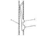
図5は、ロッド7の、流線形プッシュボタン4と一体化した下はじき5を取り付けた部分の断面図である。スライダーがこの部分を通過する際にここが障害とならないよう、適切な角度の流線形にしなければならない。また、流線形プッシュボタンの幅は、指に痛みを感じない程度には広くしておかなければならない。
【0018】
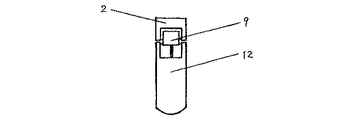
図6は、グリップ12の上にスライダー2が収納された状態をロック側正面から描いた平面図である。
【0019】
【実施例】
本発明の傘の使用者は、まず流線形プッシュボタン4を押して傘を開く(本発明においては、いわゆるジャンプ傘を想定しているが、手動で開く傘についてももちろん適用できる)。この時傘の先端は上を向いているものとする。次に押しバネ付きロック9を押し下げる。その瞬間、回転用ねじりバネ10の回転圧力によって、スライダー2が180度回転し、肩掛けフック3はグリップ12の先端とは反対方向に向き、使用者の肩に掛けやすい位置にくる。
【0020】
次に、肩掛けフックが肩にかけやすい位置にきた段階で、使用者は肩掛けフックの先端を肩に掛け、グリップを下に引く。すると、先端に向かって伸びたロッド7のガイドレール6をスライダー内周の突起(図3における20)が通る形で、スライダーはロッドの先端に向かって相対的に上昇する(実際にはグリップが下降する)。
【0021】
スライダーがロッドを相対的に上昇しはじめてすぐの段階で、流線形プッシュボタン4にぶつかるが、流線形プッシュボタンの形状(すなわち流線形)により、流線形プッシュボタン並びにそれと一体化した下はじきの露出部がスライダーの通過と共にロッド内部の空間に埋没し、スライダーの通過を妨げない。一般に普及しているジャンプ傘のプッシュボタンではこのような通過は不可能である。
【0022】
流線形プッシュボタンを越えて先端部に向かって相対的に上昇したスライダーは、ロッドの中間付近で終わるガイドレールの終端で止まる。この段階で使用者がさらにグリップを下に引くと、内蔵引きバネを介してスライダーとつながった肩掛けフックが使用者の肩の厚さに合わせてフィットする。なお、このフィットの動きはスライダーが流線形プッシュボタンを越える際に受ける抵抗の力によって達成されることもあり得る。
【0023】
上記におけるガイドレールの終端を正確にどこに設定するかを決めるには、傘のバランスと使用者の頭上の空間を如何に確保するかという点にかかっている。すなわち、肩掛けフックが使用者の肩にフィットし使用者が傘から手を放したときに、傘全体のバランスが最も安定し、かつ使用者の頭に開いた傘の内側が当たらないように設定するのが望ましい。もちろんそこには、肩掛けフックの形状やグリップの重さなども関係してくる。
【0024】
なお、本発明の傘を閉じる時は、全て片手でというわけにはいかない。肩掛けフックを下はじきの露出部の直上、あるいはグリップの直上まで下ろすことは重力によって達成可能であろうが、そこから最終的な収納段階までは両手を使わなければならない。すなわち、スライダーをグリップに押し付けるようにしながら使用開始時と逆方向に180度回転させる。回転が終わった瞬間に押しバネ付きロックが自動的に上がり、スライダーの収納が完了する。その後は普通の傘と同じように閉じることができる。なお、スライダーを回転させる前の段階でも傘を閉じることはできる。そのようにすることで窓枠などにも傘のグリップをかけることができる。
【0025】
【発明の効果】
本発明は、以上説明したように構成されているので、以下に記載されるような効果を奏する。
【0026】
まず、本発明の傘の使用者は、使用開始時の操作を片手で簡単に行うことができる。たとえば、左手に重いかばんを持ち、右手に傘をさしているときに、ポケットからキーを取り出す動作が必要になったとする。今までの一般的な傘であれば、「3本目の手が欲しい」と嘆くところであるが、本発明の傘であれば、右手の簡単な動作で引き出した肩掛けフックを肩にかけ、自由になった右手でキーを取り出すことができる。
【0027】
また、お年寄りや子供、体の不自由な方々も、本発明の傘なら弱い力でも安定性を維持してさすことができる。
【0028】
さらに、使用者は日常気軽にこれを持ち運ぶことができる。肩掛けフックがあまり邪魔にならない形で収納できるからである。どんなに機能が優れていても、日常気軽に持ち運べるようなものでないと、人はあまり使いたがらないものである。その点では、本発明の傘は今までの一般的な傘とほとんど変わらない気軽さで持ち歩くことができ、爆発的に普及する可能性がある。そしてそうなった暁には、人類の雨の日の活動能力を飛躍的に高めることになる。
【図面の簡単な説明】
【図1】本発明の傘の平面図である。
【図2】グリップ上部に取り付けるキャップを上から見た平面図である。
【図3】肩掛けフックと一体化されたスライダーを下から見た平面図である。
【図4】ロッドをグリップ直上の位置で水平に切断したものを表した斜視図である。
【図5】ロッドの、流線形プッシュボタンと一体化した下はじきを取り付けた部分の断面図である。
【図6】グリップの上にスライダーが収納された状態をロック側正面から描いた平面図である。
【符号の説明】
1 内蔵引きバネ
2 スライダー
3 肩掛けフック
4 流線形プッシュボタン
5 下はじき
6 ガイドレール
7 ロッド
8 押しバネ
9 ロック
10 回転用ねじりバネ
11 キャップ
12 グリップ[0001]
TECHNICAL FIELD OF THE INVENTION
The present invention relates to an umbrella for daily use.
[0002]
[Prior art]
The conventional general umbrella has a disadvantage that one hand is completely closed. A conventional technique for reducing this drawback is to attach a device for hanging an umbrella on the neck or shoulder using a string or a pipe. (For example, Japanese Utility Model Publication No. 5-68318, Japanese Patent Publication No. 10-33223, Japanese Patent Publication No. 2000-41824, and Japanese Patent Publication No. 2002-78517).
[0003]
[Problems to be solved by the invention]
As described above, the conventional general umbrella has a disadvantage that one hand is completely closed. The conventional technology designed to reduce this drawback has a problem that the device is too large to be carried around every day, or is not stable enough to be released.
[0004]
SUMMARY OF THE INVENTION An object of the present invention is to provide an umbrella that can be operated with one hand and that is stable enough to let go of the hand even when it is used, so that the umbrella can be operated with one hand and not easily obstructed when it is closed and carried.
[0005]
[Means for Solving the Problems]
In order to achieve the above object, in the umbrella of the present invention, a slider integrated with a shoulder hook via a built-in pull spring, and a lower flip integrated with a streamlined push button, into a rod formed with a guide rail. A lock, a torsion spring for rotation, a cap provided with a pressing spring, and a cap are attached to a grip, and the grip is fixed to the rod.
[0006]
The reason why the shoulder hook and the slider are integrated through the built-in pull spring is to fit the shoulder hook by expanding and contracting according to the thickness of the user's shoulder.
[0007]
Further, the slider has both the purpose of moving the shoulder hook using the outer periphery of the rod and the purpose of becoming the fulcrum of the shoulder hook. Because it moves around the outer circumference of the rod, there must be a cavity in the center of the slider to pass the rod.
[0008]
Of course, the diameter of the cavity is slightly larger than the diameter of the outer circumference of the rod. The degree of the difference between the diameter of the cavity and the diameter of the outer circumference of the rod determines how much resistance occurs during movement. If the difference is too small, the resistance is too large to make the movement of the hook difficult, and if the difference is too large, the possibility that the slider comes off the guide rail of the rod increases.
[0009]
The reason why the guide rail is formed on the rod is to control the movement area of the slider. That is, it is to stop the shoulder hook near the middle point of the rod, and to move the umbrella to the storage position where it does not interfere when closing the umbrella. The stop near the middle of the rod is because this position is the fulcrum that provides the most stability. In addition, the storage position that does not interfere will be a position where a zero-shape is formed in combination with a J-shaped grip. Therefore, a mechanism that can move in both directions beyond at least the bottom is needed.
[0010]
What makes this possible is a streamlined push button. That is, by making the push button streamlined, at the time of passage of the slider, the force of the passage itself causes the push button and the exposed part of the lower repellent to be almost completely buried in the rod, and when the passage is completed. It returns to its original position again.
[0011]
In addition, since the rod is formed with the guide rail as described above, there is a high possibility that a strength problem will occur with a material and a thickness that are used for a general umbrella. Therefore, it is necessary to use a rod made of a light and strong material and having a certain thickness. Probably, aluminum integral molding is suitable.
[0012]
Further, in order to satisfy the two requirements of being unobtrusive at the time of storage and being able to be operated with one hand at the start of use, a means of rotating the slider by 180 degrees just above the grip is used. For that purpose, a torsion spring for rotation with a tip exposed, a cap, an opening of a rod, and a lock mechanism are required.
[0013]
BEST MODE FOR CARRYING OUT THE INVENTION
In FIG. 1, a slider 2 integrated with a shoulder hook 3 via a built-in pull spring 1 and a lower flip 5 integrated with a streamlined push button 4 are attached to a rod 7 having a guide rail 6, and a push spring 8 is provided. The lock 9, the torsion spring 10 for rotation, and the cap 11 are attached to the grip 12, and the grip is fixed to the rod.
[0014]
FIG. 2 is a plan view of the above cap 11 as viewed from above. 13 is a hole for passing the rod, 14 is a concave portion provided so as not to hinder the operation of the lock 9, and 15 is a hole through which the tip of the torsion spring for rotation passes. The tip of the torsion spring for rotation is set to move from the upper end in FIG. 2 to the lower end in a direction opposite to the clock at the moment when the lock is released.
[0015]
FIG. 3 is a plan view of the slider 2 integrated with the shoulder hook 3 as viewed from below.
Reference numeral 16 denotes a hole through which the rod passes, and reference numeral 20 denotes a projection that engages with the guide rail of the rod. Reference numeral 17 denotes a recess required for the lock mechanism described above, and reference numeral 18 denotes a hole into which the tip of the torsion spring for rotation enters. When the slider comes down from above and rides on the grip, it is necessary to set so that the tip of the spring and the hole 18 fit well.
[0016]
FIG. 4 is a perspective view of the rod 7 cut horizontally at a position immediately above the grip 12 in FIG. 6 is a guide rail, and 19 is an opening of the guide rail. The opening 19 must be molded to allow a 180 degree rotation of the slider. In FIG. 4, the inside of the rod in this portion is drawn as a cavity. However, depending on the case, filling the cavity may be considered in order to maintain strength. Of course, in that case, only a space for burying the lower repellent integrated with the streamline push button must be kept at a minimum.
[0017]
FIG. 5 is a cross-sectional view of a part of the rod 7 to which the lower repelling member 5 integrated with the streamline push button 4 is attached. The slider must be streamlined at an appropriate angle so that it does not become an obstacle when passing through this part. Also, the width of the streamlined push button must be wide enough to avoid pain in the fingers.
[0018]
FIG. 6 is a plan view illustrating a state where the slider 2 is stored on the grip 12 from the front side on the lock side.
[0019]
【Example】
The user of the umbrella of the present invention first opens the umbrella by pressing the streamline push button 4 (in the present invention, a so-called jump umbrella is assumed, but the umbrella which is manually opened can of course be applied). At this time, the tip of the umbrella is facing upward. Next, the lock 9 with the push spring is pushed down. At that moment, the slider 2 rotates 180 degrees due to the rotational pressure of the torsion spring 10 for rotation, and the shoulder hook 3 faces in the opposite direction to the tip of the grip 12, and comes to a position where it can be easily hooked on the user's shoulder.
[0020]
Next, when the shoulder hook comes to a position where it can be easily hooked on the shoulder, the user hooks the tip of the shoulder hook on the shoulder and pulls down the grip. Then, the slider relatively rises toward the tip of the rod in a form in which the protrusion (20 in FIG. 3) on the inner periphery of the slider passes through the guide rail 6 of the rod 7 extending toward the tip (actually, the grip is moved). Descends).
[0021]
Immediately after the slider starts to relatively raise the rod, it hits the streamlined push button 4, but due to the shape of the streamlined push button (ie streamlined), the exposure of the streamlined push button as well as the integrated lower flap. The part is buried in the space inside the rod with the passage of the slider, and does not hinder the passage of the slider. Such a passage is impossible with the push button of the jump umbrella which is generally used.
[0022]
The slider, which has risen relatively towards the tip beyond the streamlined push button, stops at the end of the guide rail which ends near the middle of the rod. At this stage, when the user further pulls down the grip, the shoulder hook connected to the slider via the built-in pull spring fits according to the thickness of the user's shoulder. It should be noted that this fit movement could be achieved by the force of the resistance that the slider experiences when crossing the streamlined push button.
[0023]
Determining exactly where the ends of the guide rails are set depends on the balance of the umbrella and how to secure the space above the user's head. That is, when the shoulder hook fits the user's shoulder and the user releases the umbrella, the balance of the whole umbrella is set to the most stable, and the inside of the open umbrella does not hit the user's head It is desirable to do. Of course, it depends on the shape of the shoulder hook and the weight of the grip.
[0024]
When closing the umbrella of the present invention, it is not always possible to use one hand. Lowering the shoulder hook to just above the exposed flipper or just above the grip would be achievable by gravity, but would have to use both hands from there until the final storage stage. That is, the slider is rotated by 180 degrees in the opposite direction to the start of use while pressing the slider against the grip. The lock with the push spring automatically rises at the moment when the rotation is completed, and the storage of the slider is completed. After that you can close it like an ordinary umbrella. The umbrella can be closed even before the slider is rotated. By doing so, the umbrella grip can be applied to window frames and the like.
[0025]
【The invention's effect】
The present invention is configured as described above, and has the following effects.
[0026]
First, the user of the umbrella of the present invention can easily perform the operation at the start of use with one hand. For example, suppose that it is necessary to take out a key from a pocket while holding a heavy bag in the left hand and an umbrella in the right hand. In the case of conventional umbrellas, it is lamenting that "I want the third hand." However, with the umbrella of the present invention, the shoulder hook pulled out by a simple operation of the right hand can be hung on the shoulder, and it is free. You can remove the key with your right hand.
[0027]
In addition, the umbrella of the present invention can maintain the stability of elderly people, children and people with physical disabilities even with weak force.
[0028]
Further, the user can easily carry this on a daily basis. The reason is that the shoulder hook can be stored in a form that does not hinder too much. No matter how good it is, people don't want to use it unless it's easy to carry around. In that respect, the umbrella of the present invention can be carried around with the same ease as conventional umbrellas, and may explode. And when that happens, it will dramatically increase the ability of mankind to work on rainy days.
[Brief description of the drawings]
FIG. 1 is a plan view of an umbrella of the present invention.
FIG. 2 is a plan view of a cap attached to an upper portion of a grip as viewed from above.
FIG. 3 is a plan view of the slider integrated with the shoulder hook as viewed from below.
FIG. 4 is a perspective view showing a rod cut horizontally at a position immediately above a grip.
FIG. 5 is a cross-sectional view of a portion of a rod to which a lower repelling device integrated with a streamline push button is attached.
FIG. 6 is a plan view illustrating a state in which the slider is stored on the grip, as viewed from the front side on the lock side.
[Explanation of symbols]
REFERENCE SIGNS LIST 1 Built-in pull spring 2 Slider 3 Shoulder hook 4 Streamline push button 5 Lower flip 6 Guide rail 7 Rod 8 Push spring 9 Lock 10 Torsion spring for rotation 11 Cap 12 Grip