JP2004208917A - Cleaning utensil - Google Patents
Cleaning utensil Download PDFInfo
- Publication number
- JP2004208917A JP2004208917A JP2002381554A JP2002381554A JP2004208917A JP 2004208917 A JP2004208917 A JP 2004208917A JP 2002381554 A JP2002381554 A JP 2002381554A JP 2002381554 A JP2002381554 A JP 2002381554A JP 2004208917 A JP2004208917 A JP 2004208917A
- Authority
- JP
- Japan
- Prior art keywords
- cleaning
- dust
- collecting member
- dust collecting
- cleaning head
- Prior art date
- Legal status (The legal status is an assumption and is not a legal conclusion. Google has not performed a legal analysis and makes no representation as to the accuracy of the status listed.)
- Granted
Links
Images


Abstract
Description
【0001】
【発明の属する技術分野】
本発明は、被清掃物の表面に付着した塵や埃を叩き出して除去するのに適した清掃用品に関する。
【0002】
【従来の技術】
布団やソファーなど、表面が繊維などからなる被清掃物の表面に付着、沈積した塵や埃を除去する際には、把手部の先端に木やプラスティックからなる押打部が設けられた用具を用い、前記押打部で物品の表面を叩くことにより、塵や埃を叩き出すという手法が用いられている。
【0003】
しかし、被清掃物の表面を単に叩くだけでは、叩き出された埃が空中に散乱して周囲の空間に舞い上がり、さらには落下して被清掃物に再付着することもあって、衛生的ではない。
【0004】
そこで、以下の特許文献1には、前記押打部を覆うごみ取り用カバーに関する考案が開示されている。このカバーの表面には粘着層が設けられており、物品の表面の埃やごみを前記粘着層で吸着できるようにしている。
【0005】
【特許文献1】
実開平5−31762号公報
【0006】
【発明が解決しようとする課題】
しかし、特許文献1に記載されている粘着層を有するカバーを取り付けて、前記押打部によりふとんやソファーなどの被清掃物を叩くと、前記粘着層が被清掃物の表面に粘着して、これら表面の生地を痛めるおそれがある。また生地を痛めないように粘着層の粘着力を弱くすると、埃を充分に取ることができなくなる。
【0007】
また、特許文献1に記載のものは、ビニール製のカバーに粘着層が設けられたものであり、それ自体が通気性を有していないため、ふとんやソファーを叩くと、カバーを振ることにより風が発生して、ふとんやソファーからた叩き出した埃が舞い上がるのを避けることができない。
【0008】
本発明は、上記従来の課題を解決するためのものであり、ふとんやソファーなどの表面の生地を痛めることなく、これらから叩き出した埃を確実に集塵できる清掃用品を提供することを目的とする。
【0009】
【課題を解決するための手段】
本発明は、清掃頭部と、前記清掃頭部と一体に設けられまたは前記清掃頭部に着脱自在に設けられた把持部とを有し、
前記清掃頭部には、集塵部材を保持する保持部と、前記保持部に保持された集塵部材に対向する覆い部と、前記覆い部と覆い部との間から前記集塵部材に連通する開口部とが設けられていることを特徴とするものである。
【0010】
この清掃用品では、前記清掃頭部でふとんやソファーなどの被清掃物を叩いたときに、清掃頭部の覆い部で前記被清掃物の表面が確実に叩かれるようになる。そして、覆い部によって被清掃物の表面から叩き出された埃やごみが開口部から集塵部材に与えられて集塵部材で確実に保持されるようになる。
【0011】
例えば、前記清掃頭部は、互いに逆側に向けられる2つの清掃面を有して、それぞれの清掃面に前記覆い部と前記開口部とが現れており、前記2つの清掃面の間に前記保持部が設けられているものである。
【0012】
本発明は、集塵部材の一方の側のみに覆い部と開口部が対向していてもよいが、両側に覆い部と開口部が対向していると、清掃頭部の両面を清掃に使用することができる。
【0013】
また、前記保持部は、前記集塵部材の両側部が差し込まれる溝を有しており、この溝内に前記集塵部材を挟持する挟持手段が設けられていることが好ましい。
【0014】
前記挟持手段が設けられていると、清掃頭部を振ったときに、清掃頭部から集塵部材が離脱するのを防止できる。
【0015】
例えば、前記集塵部材は接着剤層を有しており、前記保持部に保持された集塵部材の前記接着剤層が前記覆い部および前記開口部に対向するものである。
【0016】
集塵部材が接着剤層を有するものであると、覆い部で叩き出された埃が開口部を経て集塵部材の前記接着剤層に確実に接着されて保持されるようになる。また接着剤層が覆い部で覆われていると、接着剤層が直接に被清掃物に当たりにくくなり、接着剤層で被清掃物の生地表面を傷つけるのを防止できる。
【0017】
また、前記集塵部材は、板状であり、この板を貫通する複数の貫通孔が形成されているものが好ましい。
【0018】
集塵部材に貫通孔が形成されていると、清掃頭部で被清掃物を叩いたときに、空気が清掃頭部の開口部および集塵部材の貫通孔を抜けるようになるため、被清掃物表面の埃やごみが舞い上がるのを防止しやすい。
【0019】
また、前記接着剤層と前記覆い部との間に隙間が形成されていることが好ましい。
【0020】
このように構成することにより、集塵部材を清掃頭部に取り付けられた状態で、集塵部材と清掃頭部とが接着されるのを避けることができ、集塵部材の取り付けと取り外しが容易になる。
【0021】
また、前記集塵部材は、多数の空隙を有する集塵層を有しており、前記保持部材に保持された集塵部材の前記集塵層が前記開口部に対向するものであってもよい。
【0022】
このような集塵部材を用いると、埃やごみを集塵層の空隙で捕捉することができる。この場合に、前記集塵層に接着剤を付着させておくことがさらに好ましい。
【0023】
また、前記清掃頭部の清掃面は、その中央部が隆起しているものであると、前記隆起している部分で、被清掃物のごみや埃を有効に叩き出すことができる。
【0024】
【発明の実施の形態】
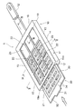
図1は、本発明の第1の実施の形態の清掃用品1を示す斜視図、図2は図1のII−II線の断面図、図3は図1のIII−III線の断面図、図4は図1のIV−IV線で断面した部分断面図、図5は集塵部材の斜視図である。
【0025】
図1に示される清掃用品1は、本体部10とこの本体部10に保持される集塵部材30を有している。本体部10は、合成樹脂材料、軽金属、木材などの剛性があり耐衝撃性に優れた材料で形成されている。本体部10は、全体が一体に形成され、あるいは各部分ごとに形成されたものが組み立てられて構成されている。
【0026】
本体部10は、清掃頭部11と、この清掃頭部11から延びる長尺状の把持部12とを有している。清掃頭部11と把持部12は、一体であってもよいし、清掃頭部11と把持部12とが分離可能に組み立てられるものであってもよい。
【0027】
前記清掃頭部11は平板形状であり、図1ないし図3に示すように、広い面積の第1の清掃面13と第2の清掃面14とが互いに逆方向に向けられて形成されており、さらに小さい面積の両側面15,15および、小さい面積の後側面16および前側面17を有している。前記把持部12は前記後側面16に接合されている。
【0028】
前記清掃頭部11の内部には挿入空間18が形成されている。そしてこの挿入空間18の周縁に集塵部材30を保持するために保持部19が形成されている。この保持部19は、図2に示すように、両側面15,15の内側に位置して縦方向に延びる保持溝19a,19aと、図3に示すように、後側面16の内側において横方向に延びる保持溝19bとを有している。保持部16を構成する保持溝19a,19aおよび保持溝19bは、前記挿入空間18の周囲を囲むように形成されている。そして、前記前側面17には、前記挿入空間18および前記両保持溝19a,19aに連通する挿入口21が開口している。
【0029】
図1に示すように、清掃頭部11の第1の清掃面13には、縦横に延びるリブとなる覆い部22と、覆い部22で囲まれた開口部23とが形成されており、この開口部23は挿入空間18に連通している。この清掃頭部11の第1の清掃面13と第2の清掃面14は対称構造であり、第2の清掃面14にも、同様に覆い部22と開口部23とが形成されている。
【0030】
図4に示すように、縦方向に延びる前記保持溝19a,19aの内部には、挟持手段となる押圧部25が設けられている。この押圧部25は、保持溝19a,19aの一方の壁部から突出して形成されている。好ましくは、この押圧部25は弾性変形可能な金属板ばね材料で形成されている。あるいは前記押圧部25が、前記保持溝19a,19aの一方の壁部を構成する樹脂が突状に一体に隆起されているものであってもよい。
【0031】
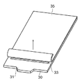
図1および図5に示すように、前記集塵部材30は板状であり、手前には摘み部31となる突起が一体に形成されている。集塵部材30は使い捨てが可能なものであり、その基板32は厚紙材で形成されている。基材32の2つの表面には接着剤層33が形成されている。この接着剤層33は、ホットメルト型などの感圧接着剤で形成された層であり、塗布後に粘着力を維持できるものである。前記基材32の2つの表面では、前記接着剤層33が中央部分に塗布されており、前記摘み部31が形成された前方部分には、接着剤層33が設けられておらず、また前記保持溝19a,19aおよび保持溝19bに保持される周囲部分にも前記接着剤層33が設けられていない。
【0032】
前記集塵部材30の前記接着剤層33が形成されている部分には、基材32を貫通する複数の貫通孔34が間隔を開けて形成されており、この貫通孔34を形成することにより、集塵部材30が通気性を有している。
【0033】
集塵部材30の通気度Fは、単位時間(s)で且つ単位面積(1m2)当たりに布を通過する空気の体積をV(m3/m2・s)とし、このときの集塵部材の表裏の圧力差をΔPとしたときに、F=ΔP/Vで表される。清掃頭部11で被清掃物を叩くときに、清掃頭部で過大な空気流を生じさせないようにするためには、前記ΔPは、前記Vを0.04(m3/m2・s)としたときに、150mmH2O以上であることが好ましい。前記ΔPを(Pa)に換算して、前記通気度Fを求めると、Fは、2.72×10−5(m3/m2・S・Pa)以上が好ましい。
本実施の形態の清掃用品1の使用方法を説明する。
【0034】
図5に示すように、清掃頭部11に取付ける前の集塵部材30では、基材32の両面に形成された接着剤層33,33が離型シート35により覆われている。前記離型シート35を剥がし、摘み部31を掴んで清掃頭部11の挿入口21から挿入空間18内に挿入し、集塵部材30の接着剤層33,33が形成されていない両側部を保持溝19a,19aに挿し込む。集塵部材30は両側部が保持溝19a,19aに案内されて挿し込まれるとともに奥まで挿し込んだ時点で、集塵部材30の挿入側の先部が、図3に示す保持溝19bで保持される。
【0035】
集塵部材30が清掃頭部11に保持された状態で、図1に示すように第1の清掃面13と第2の清掃面14の双方において、接着剤層33,33が覆い部22で覆われるが、図2および図3に示すように、接着剤層33,33と覆い部22との間には隙間が形成されて、接着剤層33,33が、覆い部22に直接に当たらないようになっている。集塵部材30の接着剤層33,33は、挿入空間18内において清掃頭部11のいずれの場所にも接着されないため、集塵部材30を挿入し抜き出すのを容易に行うことができる。
【0036】
この清掃用品1を用いた清掃作業では、把持部12を手で掴み、清掃頭部11を、ふとん、ソファー、ベッドマット、自動車のシートなどの被清掃物に打ち付ける。清掃頭部11を被清掃物の表面に打ち付けると、第1の清掃面13または第2の清掃面14に設けられた覆い部22で被清掃物の表面が叩かれ、被清掃物の表面に付着したごみや埃、さらには被清掃物の内部に付着したごみや埃を叩き出すことができる。叩き出されたごみや埃は、開口部23から挿入空間18内に入り、集塵部材30の接着剤層33に接着されて捕捉される。
【0037】
このように、覆い部22で叩き出されて被清掃物の表面から浮き上がったごみや埃が接着剤層33によって直ちに吸着されて保持されるため、ごみや埃を周囲に飛散することなく、確実に捕捉できる。
【0038】
集塵部材30は多数の貫通孔34を有して前記通気度が前記Fの範囲に設定されていると、清掃頭部11で被清掃物を叩いたときに、清掃頭部11と被清掃物の表面との間に発生する風を抑制でき、ごみや埃が周囲に飛散するのを防止でき、接着剤層33で確実に保持できるようになる。
【0039】
清掃頭部11で被清掃物を叩いたときに、覆い部22が被清掃物の表面に当たり、集塵部材30の接着剤層33が被清掃物の表面に直接に当りにくい構造であるため、接着剤層33に被清掃物の表面の繊維が接着し、被清掃物の表面が傷むことが起きにくい。また接着剤層33が覆い部22で保護されているため、接着剤層33の粘着力が低下するのを防止できる。
【0040】
また、保持溝19a,19a内に設けられた押圧部25により、集塵部材30の両側部が保持溝19a,19a内で挟持されて保持されるため、清掃頭部11を勢いよく振っても、清掃頭部11から集塵部材30が抜け出るのを防止できる。
【0041】
集塵部材30の接着剤層33に多数のごみや埃が接着したときに、集塵部材30を抜き出して廃棄し、新たな集塵部材30を取付けて使用する。
【0042】
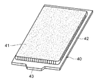
図6は、他の実施の形態の集塵部材40を示す斜視図である。
この集塵部材40は、その全体が連続気泡を有するウレタンフォームなどの合成発泡材料で形成され、または熱可塑性樹脂繊維を少なくとも一部に含むエアースルー不織布、あるいはエアーレイド方式で堆積された前記繊維を接着剤で接着した繊維ウエッブで形成されている。この繊維ウエッブの周囲42は、熱プレス、熱エンボス加工によりシート状または板状に圧縮されており、この周囲42を清掃頭部11の保持溝19a,19aおよび保持溝19bに挿し込むことができるようになっている。また、中央部分は前記合成発泡材料や繊維ウエッブにより多数の空隙が形成された集塵層41となっている。この場合も、集塵層41は、前記と同等の通気度を有していることが好ましい。
【0043】
この集塵部材40を清掃頭部11に挿し込むと、集塵層41が開口部23に対向する。清掃頭部11で被清掃物を叩いたときに、被清掃物から叩き出されたごみや埃が集塵層41の多数の空隙で保持される。なお、集塵層41でのごみや埃の捕捉力を高めるために、集塵層41の表面あるいは集塵層41の空隙の内部にも感圧接着剤が塗布されていることが好ましい。
【0044】
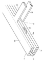
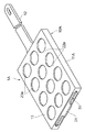
図7は本発明の第2の実施の形態の清掃用品1Aの本体部10Aを示す斜視図である。
【0045】
この本体部10Aに設けられた清掃頭部11Aは、図1に示した清掃頭部11と基本的な構造は同じである。ただし第1の清掃面13と第2の清掃面14には、挿入空間18に連通する円形の開口部23aが複数箇所形成されており、開口部23a以外の領域が覆い部22aとなっている。
【0046】
図8は、本発明の第3の実施の形態の清掃用品1Bの本体部10Bを示す斜視図である。
【0047】
この本体部10Bでは、清掃頭部11の第1の清掃面13と第2の清掃面14のそれぞれの中央部分において、覆い部23に隆起部22bが形成され、第1の清掃面13と第2の清掃面13は、その中央部が他の部分よりも盛り上がった形状となっている。この清掃頭部11の前記隆起部22bで被清掃物を叩くことにより、被清掃物からごみや埃を効果的に叩き出すことができ、このごみや埃を開口部23から集塵部材30の接着剤層33に接着させることができる。
【0048】
なお、前記隆起部22bの表面は平坦面であってもよいし、隆起部22bがさらに中央部が高くなる曲面であってもよい。また、図7に示す実施の形態においても同様に隆起部を形成することができる。
【0049】
なお、覆い部22の表面から前記隆起部22bの頂部までの高さ寸法は3〜8mmが好ましい。
【0050】
なお、本発明は前記実施の形態に限定されるものではなく、種々の変形が可能である。
【0051】
例えば、清掃頭部11の一方の面のみに覆い部22と開口部23が形成され、他方の面に開口部23が形成されていなくてもよい。あるいは他方の面が全面的に開放されているものであってもよい。この場合、集塵部材30は一方の表面にのみ接着剤層33が形成されたものを使用可能である。
【0052】
また、前記実施の形態では清掃頭部11の前側面17に挿入口21が開口しているが、この挿入口21が、後側面16に形成されており、集塵部材30を後側面16から挿入できるようにしてもよい。このように構成すると、清掃頭部11を勢いよく振ったときに、清掃頭部11から集塵部材30が離脱することを効果的に防ぐことができる。あるいは、挿入口21が側面15に開口しているものであってもよい。
【0053】
【発明の効果】
以上詳細に説明した本発明では、集塵部材を覆う覆い部によって被清掃物が叩かれるため、覆い部の叩き力により被清掃物の表面あるいは内部のごみや埃を効果的に叩き出すことができ、叩き出した埃を、前記覆い部の下に位置する集塵部材で確実に捕捉することができる。
【図面の簡単な説明】
【図1】本発明の第1の実施の形態の清掃用品を示す斜視図、
【図2】図1のII−II線の断面図、
【図3】図1のIII−III線の断面図、
【図4】図1のIV−IV線の部分断面斜視図、
【図5】集塵部材の斜視図、
【図6】集塵部材の他の実施の形態を示す斜視図、
【図7】本発明の第2の実施の形態の清掃用品を示す斜視図、
【図8】本発明の第3の実施の形態の清掃用品を示す斜視図、
【符号の説明】
1,1A,1B 清掃用品
10,10A,10B 本体部
11,11A 清掃頭部
12 把持部
13,14 清掃面
18 挿入空間
19a,19b 保持溝
22,22a 覆い部
22b 隆起部
23,23a 開口部
25 押圧部(挟持手段)
30 集塵部材
33 接着剤層
40 集塵部材
41 集塵層[0001]
BACKGROUND OF THE INVENTION
The present invention relates to a cleaning article suitable for knocking and removing dust and dirt adhering to the surface of an object to be cleaned.
[0002]
[Prior art]
When removing dust or dirt that has adhered to or deposited on the surface of an object to be cleaned, such as a futon or sofa, use a tool that has a stamping part made of wood or plastic at the tip of the handle part. A method is used in which dust or dust is knocked out by hitting the surface of an article with the hitting portion.
[0003]
However, simply hitting the surface of the object to be cleaned causes the dust that is struck out to scatter in the air and rise to the surrounding space, and then fall and reattach to the object to be cleaned. Absent.
[0004]
Therefore, the following Patent Document 1 discloses a device related to a dust removal cover that covers the pushing portion. An adhesive layer is provided on the surface of the cover so that dust and dirt on the surface of the article can be adsorbed by the adhesive layer.
[0005]
[Patent Document 1]
Japanese Utility Model Publication No. 5-31762 [0006]
[Problems to be solved by the invention]
However, when a cover having an adhesive layer described in Patent Document 1 is attached and an object to be cleaned such as a futon or a sofa is struck by the pushing portion, the adhesive layer adheres to the surface of the object to be cleaned, There is a risk of damaging the surface fabric. Further, if the adhesive force of the adhesive layer is weakened so as not to damage the fabric, the dust cannot be removed sufficiently.
[0007]
Moreover, since the thing of patent document 1 is what the adhesive layer was provided in the cover made from vinyl, and itself does not have air permeability, when a futon or a sofa is hit, by shaking a cover, It is unavoidable that wind blows and dust blown from futons and sofas soars.
[0008]
The present invention is for solving the above-described conventional problems, and an object of the present invention is to provide a cleaning article that can surely collect dust struck out without damaging the surface fabric such as a futon or a sofa. And
[0009]
[Means for Solving the Problems]
The present invention has a cleaning head and a grip portion provided integrally with the cleaning head or detachably provided on the cleaning head,
The cleaning head communicates with the dust collecting member from between a holding portion that holds the dust collecting member, a cover portion that faces the dust collecting member held by the holding portion, and between the cover portion and the covering portion. And an opening to be provided.
[0010]
In this cleaning article, when the object to be cleaned such as a futon or a sofa is struck by the cleaning head, the surface of the object to be cleaned is surely struck by the cover of the cleaning head. And the dust and the dust which were knocked out from the surface of the to-be-cleaned object by the cover part are given to the dust collecting member from the opening part, and come to be reliably held by the dust collecting member.
[0011]
For example, the cleaning head has two cleaning surfaces directed opposite to each other, and the covering portion and the opening portion appear on each cleaning surface, and the cleaning head is between the two cleaning surfaces. A holding part is provided.
[0012]
In the present invention, the cover and the opening may be opposed to only one side of the dust collecting member, but when the cover and the opening are opposed to both sides, both surfaces of the cleaning head are used for cleaning. can do.
[0013]
Moreover, it is preferable that the said holding | maintenance part has a groove | channel into which the both sides of the said dust collection member are inserted, and the clamping means which clamps the said dust collection member in this groove | channel is provided.
[0014]
When the clamping means is provided, it is possible to prevent the dust collecting member from being detached from the cleaning head when the cleaning head is shaken.
[0015]
For example, the dust collecting member has an adhesive layer, and the adhesive layer of the dust collecting member held by the holding part faces the cover part and the opening part.
[0016]
When the dust collecting member has an adhesive layer, the dust struck out by the cover portion is securely bonded and held on the adhesive layer of the dust collecting member through the opening. Moreover, when the adhesive layer is covered with the covering portion, the adhesive layer is less likely to directly hit the object to be cleaned, and the cloth layer of the object to be cleaned can be prevented from being damaged by the adhesive layer.
[0017]
The dust collecting member is preferably plate-shaped and has a plurality of through holes penetrating the plate.
[0018]
If the dust collection member has a through-hole, when the object to be cleaned is struck by the cleaning head, air will pass through the opening of the cleaning head and the through-hole of the dust collection member. It is easy to prevent dust and dirt on the surface of the object from flying up.
[0019]
Moreover, it is preferable that the clearance gap is formed between the said adhesive bond layer and the said cover part.
[0020]
With this configuration, it is possible to avoid adhesion of the dust collecting member and the cleaning head in a state where the dust collecting member is attached to the cleaning head, and easy attachment and removal of the dust collecting member. become.
[0021]
The dust collection member may have a dust collection layer having a large number of voids, and the dust collection layer of the dust collection member held by the holding member may be opposed to the opening. .
[0022]
When such a dust collecting member is used, dust and dust can be captured in the gap of the dust collecting layer. In this case, it is more preferable to adhere an adhesive to the dust collection layer.
[0023]
In addition, if the central portion of the cleaning surface of the cleaning head is raised, dust and dust of the object to be cleaned can be struck out effectively at the raised portion.
[0024]
DETAILED DESCRIPTION OF THE INVENTION
1 is a perspective view showing a cleaning article 1 according to a first embodiment of the present invention, FIG. 2 is a sectional view taken along line II-II in FIG. 1, and FIG. 3 is a sectional view taken along line III-III in FIG. 4 is a partial cross-sectional view taken along line IV-IV in FIG. 1, and FIG. 5 is a perspective view of the dust collecting member.
[0025]
The cleaning article 1 shown in FIG. 1 has a
[0026]
The
[0027]
The cleaning
[0028]
An
[0029]
As shown in FIG. 1, the
[0030]
As shown in FIG. 4, a
[0031]
As shown in FIGS. 1 and 5, the
[0032]
A plurality of through
[0033]
The air permeability F of the
A method for using the cleaning article 1 of the present embodiment will be described.
[0034]
As shown in FIG. 5, in the
[0035]
In a state where the
[0036]
In the cleaning operation using the cleaning article 1, the
[0037]
In this way, the dust and dust that have been knocked out by the
[0038]
When the
[0039]
When the object to be cleaned is struck with the cleaning
[0040]
Further, since both sides of the
[0041]
When a large amount of dust or dust adheres to the
[0042]
FIG. 6 is a perspective view showing a
The
[0043]
When the
[0044]
FIG. 7 is a perspective view showing the
[0045]
The cleaning
[0046]
FIG. 8 is a perspective view showing the
[0047]
In the
[0048]
The surface of the raised
[0049]
In addition, as for the height dimension from the surface of the
[0050]
In addition, this invention is not limited to the said embodiment, A various deformation | transformation is possible.
[0051]
For example, the
[0052]
Further, in the embodiment, the
[0053]
【The invention's effect】
In the present invention described in detail above, the object to be cleaned is beaten by the cover portion covering the dust collecting member, so that the surface of the object to be cleaned or dust or dust inside the object to be cleaned can be effectively beaten by the hitting force of the cover portion. The dust that has been knocked out can be reliably captured by the dust collecting member located under the cover.
[Brief description of the drawings]
FIG. 1 is a perspective view showing a cleaning article according to a first embodiment of the present invention;
FIG. 2 is a cross-sectional view taken along line II-II in FIG.
FIG. 3 is a cross-sectional view taken along line III-III in FIG.
4 is a partial cross-sectional perspective view taken along line IV-IV in FIG.
FIG. 5 is a perspective view of a dust collecting member,
FIG. 6 is a perspective view showing another embodiment of the dust collecting member,
FIG. 7 is a perspective view showing a cleaning article according to a second embodiment of the present invention;
FIG. 8 is a perspective view showing a cleaning article according to a third embodiment of the present invention,
[Explanation of symbols]
1, 1A,
30
Claims (8)
前記清掃頭部には、集塵部材を保持する保持部と、前記保持部に保持された集塵部材に対向する覆い部と、前記覆い部と覆い部との間から前記集塵部材に連通する開口部とが設けられていることを特徴とする清掃用品。A cleaning head and a gripping part provided integrally with the cleaning head or detachably provided on the cleaning head;
The cleaning head communicates with the dust collecting member from between a holding portion that holds the dust collecting member, a cover portion that faces the dust collecting member held by the holding portion, and between the cover portion and the covering portion. A cleaning article characterized in that an opening is provided.
Priority Applications (1)
| Application Number | Priority Date | Filing Date | Title |
|---|---|---|---|
| JP2002381554A JP4263475B2 (en) | 2002-12-27 | 2002-12-27 | Cleaning supplies |
Applications Claiming Priority (1)
| Application Number | Priority Date | Filing Date | Title |
|---|---|---|---|
| JP2002381554A JP4263475B2 (en) | 2002-12-27 | 2002-12-27 | Cleaning supplies |
Publications (2)
| Publication Number | Publication Date |
|---|---|
| JP2004208917A true JP2004208917A (en) | 2004-07-29 |
| JP4263475B2 JP4263475B2 (en) | 2009-05-13 |
Family
ID=32817444
Family Applications (1)
| Application Number | Title | Priority Date | Filing Date |
|---|---|---|---|
| JP2002381554A Expired - Fee Related JP4263475B2 (en) | 2002-12-27 | 2002-12-27 | Cleaning supplies |
Country Status (1)
| Country | Link |
|---|---|
| JP (1) | JP4263475B2 (en) |
Cited By (4)
| Publication number | Priority date | Publication date | Assignee | Title |
|---|---|---|---|---|
| US7740412B2 (en) | 2005-01-28 | 2010-06-22 | S.C. Johnson & Son, Inc. | Method of cleaning using a device with a liquid reservoir and replaceable non-woven pad |
| US7891898B2 (en) | 2005-01-28 | 2011-02-22 | S.C. Johnson & Son, Inc. | Cleaning pad for wet, damp or dry cleaning |
| US7976235B2 (en) | 2005-01-28 | 2011-07-12 | S.C. Johnson & Son, Inc. | Cleaning kit including duster and spray |
| US8893347B2 (en) | 2007-02-06 | 2014-11-25 | S.C. Johnson & Son, Inc. | Cleaning or dusting pad with attachment member holder |
-
2002
- 2002-12-27 JP JP2002381554A patent/JP4263475B2/en not_active Expired - Fee Related
Cited By (5)
| Publication number | Priority date | Publication date | Assignee | Title |
|---|---|---|---|---|
| US7740412B2 (en) | 2005-01-28 | 2010-06-22 | S.C. Johnson & Son, Inc. | Method of cleaning using a device with a liquid reservoir and replaceable non-woven pad |
| US7891898B2 (en) | 2005-01-28 | 2011-02-22 | S.C. Johnson & Son, Inc. | Cleaning pad for wet, damp or dry cleaning |
| US7976235B2 (en) | 2005-01-28 | 2011-07-12 | S.C. Johnson & Son, Inc. | Cleaning kit including duster and spray |
| US8657515B2 (en) | 2005-01-28 | 2014-02-25 | S.C. Johnson & Son, Inc. | Cleaning kit including duster and spray |
| US8893347B2 (en) | 2007-02-06 | 2014-11-25 | S.C. Johnson & Son, Inc. | Cleaning or dusting pad with attachment member holder |
Also Published As
| Publication number | Publication date |
|---|---|
| JP4263475B2 (en) | 2009-05-13 |
Similar Documents
| Publication | Publication Date | Title |
|---|---|---|
| EP1595490B2 (en) | Cleaning sheet | |
| JP4050035B2 (en) | Handy mop | |
| US20070136973A1 (en) | Floor cleaning system | |
| US7694379B2 (en) | Absorbent cleaning pad and method of making same | |
| US8850649B2 (en) | Cleaning tool with upstanding stems and method of cleaning a surface | |
| KR101187526B1 (en) | A sheet for cleaning | |
| US7841040B2 (en) | Absorbent cleaning pad with extended portion for use with a cleaning implement | |
| US20090032059A1 (en) | Cleaning material and method of cleaning a surface | |
| US7591040B2 (en) | Cleaning tool for removing larger and smaller sized particles | |
| JP2011104111A (en) | Cleaning sheet and cleaning implement | |
| JP4263475B2 (en) | Cleaning supplies | |
| JPH1189776A (en) | Cleaning cloth and tool | |
| US20060010634A1 (en) | Cleaning pad and method of obtaining a clean surface thereon | |
| JP4017515B2 (en) | Cleaning sheet | |
| JP3544177B2 (en) | Cleaning supplies | |
| JP5879050B2 (en) | Cleaning sheet | |
| JP4073267B2 (en) | Cleaning sheet | |
| JP3948820B2 (en) | Cleaning sheet | |
| JP5851182B2 (en) | Cleaning tool | |
| JPH1033445A (en) | Cleaner | |
| JP3624996B2 (en) | Cleaning tool | |
| JP3034285U (en) | Cleaning tools | |
| JP3450605B2 (en) | Cleaning tools | |
| JP3008895U (en) | Microphone cover | |
| TWM384002U (en) | Dust separation broom structure |
Legal Events
| Date | Code | Title | Description |
|---|---|---|---|
| A621 | Written request for application examination |
Free format text: JAPANESE INTERMEDIATE CODE: A621 Effective date: 20051129 |
|
| RD04 | Notification of resignation of power of attorney |
Free format text: JAPANESE INTERMEDIATE CODE: A7424 Effective date: 20060216 |
|
| RD02 | Notification of acceptance of power of attorney |
Free format text: JAPANESE INTERMEDIATE CODE: A7422 Effective date: 20060206 |
|
| A977 | Report on retrieval |
Free format text: JAPANESE INTERMEDIATE CODE: A971007 Effective date: 20080423 |
|
| A131 | Notification of reasons for refusal |
Free format text: JAPANESE INTERMEDIATE CODE: A131 Effective date: 20080812 |
|
| A521 | Written amendment |
Free format text: JAPANESE INTERMEDIATE CODE: A523 Effective date: 20081010 |
|
| TRDD | Decision of grant or rejection written | ||
| A01 | Written decision to grant a patent or to grant a registration (utility model) |
Free format text: JAPANESE INTERMEDIATE CODE: A01 Effective date: 20090120 |
|
| A01 | Written decision to grant a patent or to grant a registration (utility model) |
Free format text: JAPANESE INTERMEDIATE CODE: A01 |
|
| A61 | First payment of annual fees (during grant procedure) |
Free format text: JAPANESE INTERMEDIATE CODE: A61 Effective date: 20090212 |
|
| FPAY | Renewal fee payment (event date is renewal date of database) |
Free format text: PAYMENT UNTIL: 20120220 Year of fee payment: 3 |
|
| R150 | Certificate of patent or registration of utility model |
Ref document number: 4263475 Country of ref document: JP Free format text: JAPANESE INTERMEDIATE CODE: R150 Free format text: JAPANESE INTERMEDIATE CODE: R150 |
|
| FPAY | Renewal fee payment (event date is renewal date of database) |
Free format text: PAYMENT UNTIL: 20120220 Year of fee payment: 3 |
|
| FPAY | Renewal fee payment (event date is renewal date of database) |
Free format text: PAYMENT UNTIL: 20130220 Year of fee payment: 4 |
|
| R250 | Receipt of annual fees |
Free format text: JAPANESE INTERMEDIATE CODE: R250 |
|
| FPAY | Renewal fee payment (event date is renewal date of database) |
Free format text: PAYMENT UNTIL: 20140220 Year of fee payment: 5 |
|
| R250 | Receipt of annual fees |
Free format text: JAPANESE INTERMEDIATE CODE: R250 |
|
| R250 | Receipt of annual fees |
Free format text: JAPANESE INTERMEDIATE CODE: R250 |
|
| R250 | Receipt of annual fees |
Free format text: JAPANESE INTERMEDIATE CODE: R250 |
|
| R250 | Receipt of annual fees |
Free format text: JAPANESE INTERMEDIATE CODE: R250 |
|
| R250 | Receipt of annual fees |
Free format text: JAPANESE INTERMEDIATE CODE: R250 |
|
| R250 | Receipt of annual fees |
Free format text: JAPANESE INTERMEDIATE CODE: R250 |
|
| LAPS | Cancellation because of no payment of annual fees |