【0001】
【産業上の利用分野】
本発明は、基板の搬送装置、特に半導体ウエハ等の基板の搬送装置に関する。
【0002】
【従来の技術】
従来、イオンドープ、成膜、エッチング等の各種処理を半導体ウエハ等の基板Wに施す基板処理システムとして、スループット及び歩留まりの向上を目的とし、同じ処理を行う複数の基板処理装置や、異なる処理を行う複数の基板処理装置が共通の搬送室を介して放射状に配設されたクラスタ基板処理システムが知られている。
【0003】
このクラスタ基板処理システムでは、各基板処理装置において処理済の基板Wと未処理の基板Wとを入れ換えるため、基板Wを搬送する搬送機構が搬送室に配設される。このような搬送機構の代表例としては、下記に示すスカラアーム式ハンドリング機構及びフロッグレッグ式ハンドリング機構が知られている(例えば、特許文献1参照。)。
【0004】
図12は、スカラアーム式ハンドリング機構が配設された従来のクラスタ基板処理システムの概略構成を示す平面図である。
【0005】
図12において、クラスタ基板処理システム120は、その内部において基板Wを処理する2つの基板処理装置121と、ウエハカセット(不図示)から基板Wを搬出入するロードロック室122と、ロードロック室122から基板Wの搬入、又はロードロック室122への基板Wの搬出を行う2つのウエハ搬出入室123と、基板処理装置121及びウエハ搬出入室123を接続する搬送室124とを備え、搬送室124はその内部にスカラアーム式ハンドリング機構125を有する。
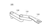
【0006】
スカラアーム式ハンドリング機構125は、図13に示すように、棒状の第1アーム部130、棒状の第2アーム部131及び基板Wを拘持する拘持部132とから成り、第1アーム部130は、その一端においてクラスタ基板処理システム120を上方から見たときに回転自在となるように、搬送室124の床面に接続され、第2アーム部131は、その一端において第1アーム部130の他端に回転自在に接続され、拘持部132は、第2アーム部131の他端に接続される。
【0007】
スカラアーム式ハンドリング機構125において基板Wを搬送するとき、第1アーム部130、第2アーム部131及び拘持部132が協動して基板Wを基板処理装置121やウエハ搬出入室123における所望の位置に搬出入する。
【0008】
図14は、フロッグレッグ式ハンドリング機構が配設された従来のクラスタ基板処理システムの概略構成を示す平面図である。
【0009】
図14において、クラスタ基板処理システム140は、その内部において基板Wを処理する4つの基板処理装置141と、ロードロック室(不図示)から基板Wの搬入、又はロードロック室への基板Wの搬出を行う2つのウエハ搬出入室142と、基板処理装置141及びウエハ搬出入室142を接続する搬送室143とを備え、搬送室143はその内部にフロッグレッグ式ハンドリング機構144を有する。
【0010】
フロッグレッグ式ハンドリング機構144は、搬送室143の床面に垂直に立設された柱状の基部145と、平行に配設された2本の棒状部材からなる第1アーム部146及び棒状の第2アーム部147が構成する2つのフロッグレッグ部148と、基板Wを拘持する拘持部149とから成り、第1アーム部146は、その一端において基部145の側面に周方向に関して移動自在に接続され、第2アーム部147は、その一端において第1アーム部146の他端に回転自在に接続され、拘持部149は、第2アーム部147の他端に接続される。
【0011】
フロッグレッグ式ハンドリング機構144において基板Wを搬送するとき、第1アーム部146、第2アーム部147及び拘持部149が協動して基板Wを基板処理装置141やウエハ搬出入室142における所望の位置に搬出入する。
【0012】
【特許文献1】
特開平10−154739号公報(第1図、第3図)
【0013】
【発明が解決しようとする課題】
しかしながら、図15に示すように、クラスタ基板処理システム120における搬送室124内部において、第1アーム部130が回転移動する空間150には干渉物となるものを配設することができず、搬送室124内部の空間容積が大となる傾向がある。また、基板Wの基板処理装置121への搬入の際、基板処理装置121内部の真空度を維持するために、搬送室124内部は減圧されるが、搬送室124内部を完全に真空にすることは困難であり、多少の気体が残留する。
【0014】
このとき、上述したように搬送室124内部の空間容積が大となると、第1アーム部130が回転移動することによって空間150において気流の乱れが発生してパーティクル等が巻上げられ、該巻き上げられたパーティクル等が基板Wに付着するという問題があった。
【0015】
また、第1アーム部130は棒状であるため、長手方向において撓み量が大となる傾向がある。このように撓み量が大となると、第2アーム部131や拘持部132の位置精度が悪化し、基板Wの搬送時に搬送室124の筐体と干渉するおそれがあるため、搬送室124の開口部151の面積を大きくする必要があるが、開口部151の開口部の面積を大きくすると外部からのパーティクル等の侵入が容易となり、その結果、侵入したパーティクル等が基板Wに付着するという問題があった。
【0016】
これらの問題はフロッグレッグ式ハンドリング機構144が配設されたクラスタ基板処理システム140でも同様に発生する。
【0017】
本発明の目的は、パーティクル等の基板への付着を防止できる搬送装置を提供することにある。
【0018】
【課題を解決するための手段】
上記目的を達成するために、請求項1記載の基板の搬送装置は、基板を支持する少なくとも2つの腕部材を備えると共に所定の筐体内部に配設され、且つ前記腕部材の一方はその一端において前記腕部材の他方に回転自在に接続される基板の搬送装置において、前記腕部材の一方は、中心部が前記筐体に回転自在に接続された円柱体から成り、前記円柱体の半径は、前記中心部から前記一端までの距離よりも大きいことを特徴とする。
【0019】
請求項1記載の搬送装置によれば、少なくとも2つの腕部材を備えると共に筐体内部に配設された基板の搬送装置において、腕部材の一方は、中心部が筐体に回転自在に接続された円柱体から成り、円柱体の半径は中心部から一端までの距離よりも大きいので、筐体内部の空間容積が小さくなり、腕部材の一方の回転による気流の乱れの発生を防止できると共に、腕部材の一方における剛性の向上によって撓み量が小さくなり、筐体における腕部材用の開口部の面積を小さくできる。その結果、パーティクル等の巻き上げや進入を防止でき、もってパーティクル等の基板への付着を防止できる。また、筐体内部の空間容積が小さくなるため、筐体内部の真空化を迅速に実行することができ、もってスループットを向上できる。
【0020】
請求項2記載の搬送装置は、請求項1記載の搬送装置において、前記筐体は、円柱状の腕部材収容孔を備え、該腕部材収容孔は前記円柱体を収容することを特徴とする。
【0021】
請求項2記載の搬送装置によれば、筐体は円柱状の腕部材収容孔を備え、該腕部材収容孔は前記円柱体を収容するので、筐体内部の空間容積がより小さくなり、もってパーティクル等の基板への付着を確実に防止できる。
【0022】
請求項3記載の搬送装置は、請求項2記載の搬送装置において、前記腕部材収容孔の直径は、前記円柱体の直径とほぼ一致することを特徴とする。
【0023】
請求項3記載の搬送装置によれば、腕部材収容孔の直径は、円柱体の直径とほぼ一致するので、筐体内部の空間容積がさらに小さくなり、もってパーティクル等の基板への付着をより確実に防止できる。
【0024】
請求項4記載の搬送装置は、請求項1乃至3のいずれか1項に記載の搬送装置において、前記円柱体は中心軸方向に沿って穿孔された貫通孔を有し、前記筐体は前記貫通孔に対応する位置に穿孔された他の貫通孔を有することを特徴とする。
【0025】
請求項4記載の搬送装置によれば、腕部材の一方である円柱体は中心軸方向に沿って穿孔された貫通孔を有し、筐体は貫通孔に対応する位置に穿孔された他の貫通孔を有するので、当該貫通孔及び他の貫通孔を介して筐体内部の気体排出の効率を向上することができ、もってスループットをさらに向上できる。
【0026】
請求項5記載の搬送装置は、請求項1乃至4のいずれか1項に記載の搬送装置において、前記円柱体には、その中心軸に沿った円柱孔が穿孔されていることを特徴とする。
【0027】
請求項5記載の搬送装置によれば、腕部材の一方である円柱体にはその中心軸に沿った円柱孔が穿孔されているので、腕部材の一方を軽量化でき、もって慣性モーメントを低減できる。その結果、基板の搬送速度を向上でき、よりスループットを向上できる。
【0028】
上記目的を達成するために、請求項6記載の搬送装置は、基板を支持する少なくとも2つの腕部材を備えると共に筐体内部に配設され、且つ前記腕部材の一方はその一端において前記腕部材の他方の一端と回転自在に接続される屈折構造を少なくとも2つ備える基板の搬送装置において、前記屈折構造の一方における前記腕部材の一方は、中心部が前記筐体に回転自在に接続された円柱体から成り、前記円柱体の半径は、前記中心部から前記腕部材の他方の一端までの距離よりも小さく、且つ前記屈折構造の他方における前記腕部材の一方は、前記円柱体の中心軸に沿って配設された環状体であることを特徴とする。
【0029】
請求項6記載の搬送装置によれば、少なくとも2つの腕部材から成る2つの屈折構造を備えると共に筐体内部に配設された基板の搬送装置では、屈折構造の一方における腕部材の一方は、中心部が筐体に回転自在に接続された円柱体から成り、円柱体の半径は中心部から腕部材の他方の一端までの距離よりも小さく、且つ屈折構造の他方における腕部材の一方は、円柱体の中心軸に沿って配設された環状体であるので、筐体内部の空間容積が小さくなり、腕部材の一方の回転による気流の乱れの発生を防止できると共に、腕部材の一方における剛性の向上によって撓み量が小さくなり、筐体の開口部の面積を小さくできる。その結果、パーティクル等の巻き上げや進入を防止でき、もってパーティクル等の基板への付着を防止できる。また、筐体内部の空間容積が小さくなるため、筐体内部の真空化を迅速に実行することができ、もってスループットを向上できる。
【0030】
請求項7記載の搬送装置は、請求項6記載の搬送装置において、前記筐体は、円柱状の腕部材収容孔を備え、該腕部材収容孔は前記環状体を収容することを特徴とする。
【0031】
請求項7記載の搬送装置によれば、筐体は円柱状の腕部材収容孔を備え、該腕部材収容孔は前記環状体を収容するので、筐体内部の空間容積がより小さくなり、もってパーティクル等の基板への付着を確実に防止できる。
【0032】
請求項8記載の搬送装置は、請求項7記載の搬送装置において、前記腕部材収容孔の直径は、前記環状体の外径とほぼ一致することを特徴とする。
【0033】
請求項8記載の搬送装置によれば、腕部材収容孔の直径は、環状体の外径とほぼ一致するので、筐体内部の空間容積がさらに小さくなり、もってパーティクル等の基板への付着をより確実に防止できる。
【0034】
請求項9記載の搬送装置は、請求項6乃至8のいずれか1項に記載の搬送装置において、前記屈折構造の一方の前記腕部材の一方における前記腕部材の他方に対する回転軸から前記中心部までの距離は、前記屈折構造の他方の前記腕部材の一方における前記腕部材の他方に対する回転軸から前記中心部までの距離と等しいことを特徴とする。
【0035】
請求項9記載の搬送装置によれば、屈折構造の一方の腕部材の一方における腕部材の他方に対する回転軸から中心部までの距離は、屈折構造の他方の腕部材の一方における腕部材の他方に対する回転軸から中心部までの距離と等しいので、円柱体と環状体の回転角度を揃えれば、屈折構造の動作を同調させることができ、基板を正確に所望の位置に搬送できる。
【0036】
請求項10記載の搬送装置は、請求項6乃至9のいずれか1項に記載の搬送装置において、前記屈折構造の各々を、前記腕部材の他方の他端において互いに接続する基板拘持部を備えることを特徴とする。
【0037】
請求項10記載の搬送装置によれば、屈折構造の各々を、腕部材の他方の他端において互いに接続する基板拘持部を備えるので、屈折構造の動作をより正確に同調させることができ、基板をより正確に所望の位置に搬送できる。
【0038】
請求項11記載の搬送装置は、請求項10記載の搬送装置において、前記基板拘持部は、前記屈折構造の一方における前記腕部材の他方の回転角と、前記屈折構造の他方における前記腕部材の他方の回転角とを整合する整合構造を有することを特徴とする。
【0039】
請求項11記載の搬送装置によれば、基板拘持部は、屈折構造の一方における腕部材の他方の回転角と、屈折構造の他方における腕部材の他方の回転角とを整合する整合構造を有するので、屈折構造の動作をさらに正確に同調させることができ、基板をさらに正確に所望の位置に搬送できる。
【0040】
請求項12記載の搬送装置は、請求項6乃至11のいずれか1項に記載の搬送装置において、前記円柱体は中心軸方向に沿って穿孔された貫通孔を有し、前記環状体は前記貫通孔に対応する位置に穿孔された他の貫通孔を有し、且つ前記筐体は前記他の貫通孔に対応する位置に穿孔されたさらに他の貫通孔を有することを特徴とする。
【0041】
請求項12記載の搬送装置によれば、円柱体は中心軸方向に沿って穿孔された貫通孔を有し、環状体は貫通孔に対応する位置に穿孔された他の貫通孔を有し、且つ筐体は他の貫通孔に対応する位置に穿孔されたさらに他の貫通孔を有するので、当該貫通孔、他の貫通孔及びさらに他の貫通孔を介して筐体内部の気体排出の効率を向上することができ、もってスループットをさらに向上できる。
【0042】
請求項13記載の搬送装置は、請求項6乃至12のいずれか1項に記載の搬送装置において、前記円柱体には、その中心軸に沿った円柱孔が穿孔されていることを特徴とする。
【0043】
請求項13記載の搬送装置によれば、屈折構造の一方における腕部材の一方を軽量化でき、もって慣性モーメントを低減できる。その結果、基板の搬送速度を向上でき、よりスループットを向上できる。
【0044】
【発明の実施の形態】
以下、本発明の第1の実施の形態に係る搬送装置について詳述する。
【0045】
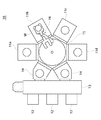
図1は、本発明の第1の実施の形態に係る搬送装置が配設されたクラスタ基板処理システムの概略構成を示す平面図である。
【0046】
図1において、クラスタ基板処理システム10は、その内部において基板Wを処理する4つの基板処理装置11と、基板Wを格納するウエハカセット12から基板Wを搬出入するロードロック室13と、ロードロック室13から基板Wの搬入、又はロードロック室13への基板Wの搬出を行う2つのウエハ搬出入室14と、基板処理装置11及びウエハ搬出入室14を接続する搬送室15とを備える。また、クラスタ基板処理システム10は、搬送室15の内部において基板ハンドリング機構16を有する。基板ハンドリング機構16は、基板Wをウエハ搬出入室14や基板処理装置11へ搬出入する。
【0047】
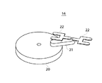
図2は、図1のクラスタ基板処理システム10における基板ハンドリング機構16の概略構成を示す斜視図である。
【0048】
図2において、基板ハンドリング機構16は、円柱体である回転部20、棒体であるアーム部21及び基板Wを拘持する拘持部22とから成り、回転部20は、クラスタ基板処理システム10を上方から見たときに、その中心部において回転自在に搬送室15の床面に接続され、アーム部21は、その一端において回転部20の外縁近傍と回転自在に接続され、拘持部22はアーム部21の他端に回転自在に接続される。また、回転部20の半径は、回転部20の中心部から回転部20に対するアーム部21の回転軸までの距離よりも大きい。そして、基板ハンドリング機構16において基板Wを搬送するとき、回転部20、アーム部21及び拘持部22が協動して基板Wを基板処理装置11やウエハ搬出入室14における所望の位置に搬出入する。
【0049】
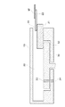
図3は、図2の基板ハンドリング機構16を内包する搬送室15の概略構成を示す断面図である。
【0050】
図3において、搬送室15は、その内部の上方にアーム部21及び拘持部22が回転移動可能な移動空間30を有し、該移動空間30は搬送室15の側壁部に配設された開口部31を介して基板処理装置11やウエハ搬出入室14の内部空間と接続される。また、搬送室15は、その内部の下方に回転部20を収容する収容空間32を有し、該収容空間32はクラスタ基板処理システム10の上下方向に沿った中心軸を有する円柱状の空間である。回転部20の直径は、収容空間32の直径より若干小さく設定されるので、回転部20の中心軸が収容空間32の中心軸と一致するように、回転部20が収容空間32に収容されたとき、回転部20は収容空間32の容積をほぼ充填する。このとき、回転部20は棒状部材でなく、円柱状部材であるため、その半径方向に関する撓み量が小さくなり、開口部31の面積の設定において当該撓み量を考慮する必要はない。
【0051】
また、回転部20は中心軸方向に沿って穿孔された排気ポート33を有し、搬送室15は、回転部20が回転する前のイニシャル状態にあるときにおいて排気ポート33に対応する位置に穿孔された排気ポート34を底部に有する。
【0052】
次に、基板ハンドリング機構16の基板搬送方法について図面を用いて説明する。
【0053】
図4は、図2の基板ハンドリング機構16が実行する基板Wの直線方向に関する搬送方法を説明する図である。
【0054】
まず、基板Wを拘持した拘持部22のアーム部21に対する位置関係を固定し、且つアーム部21の回転部20に対する位置関係を固定したまま、回転部20をその中心軸回りに所定の角度だけ回転させることにより、拘持部22を、基板Wを搬入すべき基板処理装置11aに正対させる(図4(a))。
【0055】
そして、さらに回転部20を反時計回りに所定の回転速度で回転させるとき、アーム部21を時計回りに同じ所定の回転速度で回転させることによって、拘持部22を基板処理装置11aへ直線状に移動させ(図4(b))、基板処理装置11aの内部へ進入した拘持部22が所望の位置に到達したとき、回転部20及びアーム部21の回転を中止することによって基板Wを基板処理装置11aにおける所望の位置へ搬送する(図4(c))。
【0056】
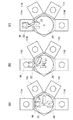
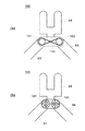
図5は、図2の基板ハンドリング機構16が実行する基板Wの方向変換を伴う搬送方法を説明する図である。
【0057】
まず、図4の直線方向に関する搬送方法の手順を逆に実行することにより、基板処理装置11aにおいて処理の終了した基板Wを搬出し(図5(a))、その後、基板Wを拘持した拘持部22のアーム部21に対する位置関係を固定し、且つアーム部21の回転部20に対する位置関係を固定したまま、回転部20をその中心軸回りに所定の角度だけ回転させることにより、基板Wを拘持した拘持部22を、基板Wを搬入すべき基板処理装置11bに正対させる(図5(b))。
【0058】
そして、図4の直線方向に関する搬送方法の手順を実行することによって基板Wを基板処理装置11bにおける所望の位置に搬送する(図5(c))。
【0059】
本発明の第1の実施の形態によれば、回転部20は、中心部が搬送室15に回転自在に接続された円柱体から成り、回転部20の半径は、回転部20の中心部から回転部20に対するアーム部21の回転軸までの距離よりも大きく、回転部20が収容空間32に収容されたとき、回転部20は収容空間32の容積をほぼ充填するので、搬送室15内部の空間容積が小さくなり、回転部20の回転による気流の乱れの発生を防止できると共に、回転部20の剛性の向上によって半径方向に関する撓み量が小さくなり、搬送室15の開口部の面積を小さくできる。その結果、パーティクル等の巻き上げや進入を防止でき、もってパーティクル等の基板への付着を防止できる。また、搬送室15内部の空間容積が小さくなるため、搬送室15内部の真空化を迅速に実行することができ、もってスループットを向上できる。
【0060】
また、回転部20は中心軸方向に沿って穿孔された排気ポート33を有し、搬送室15は、回転部20が回転する前のイニシャル状態にあるとき、排気ポート33に対応する位置に穿孔された排気ポート34を底部に有するので、排気ポート33及び排気ポート34を介して搬送室15内部の気体排出の効率を向上することができ、もってスループットをさらに向上できる。
【0061】
上述した基板ハンドリング機構16において、回転部20には、その中心軸に沿った円柱孔が穿孔されていてもよく、これにより、回転部20を軽量化でき、もって慣性モーメントを低減できる。その結果、基板Wの搬送速度を向上でき、よりスループットを向上できる。
【0062】
次に、本発明の第2の実施の形態に係る搬送装置について詳述する。
【0063】
本発明の第2の実施の形態に係る搬送装置も、上述した基板ハンドリング機構16と同様に、クラスタ基板処理システム10における搬送室15の内部に配設される。
【0064】
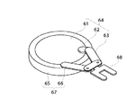
図6は、本発明の第2の実施の形態に係る搬送装置の概略構成を示す斜視図である。
【0065】
図6において、基板ハンドリング機構60は、円柱体である回転部61、板状体である延伸部62、及び棒状体である第1アーム部63から成る第1レッグ部64と、環状体である環状回転部65、及び棒状体である第2アーム部66から成る第2レッグ部67と、基板Wを拘持する拘持部68とを備える。
【0066】
回転部61は、クラスタ基板処理システム10を上方から見たときに、その中心部において回転自在に搬送室15の床面に接続され、環状回転部65は回転部61の中心軸に沿って配設される。第1レッグ部64において、延伸部62は、その一端において回転部61の外縁近傍に固定され、第1アーム部63は、その一端において延伸部62の他端と回転自在に接続される。また、第2レッグ部67において、環状回転部65は、回転部61の中心軸の廻りを回転自在に配設され、第2アーム部66は、その一端において環状回転部65に回転自在に接続される。さらに、拘持部68は、第1アーム部63及び第2アーム部66の各々と、その他端において接続される。
【0067】
また、回転部61の半径は、その中心部から延伸部62の他端までの距離よりも小さいが、第1レッグ部64における第1アーム部63の一端の回転軸から回転部61の中心部までの距離は、第2レッグ部67における第2アーム部66の一端の回転軸から環状回転部65の中心部までの距離と等しい。
【0068】
このハンドリング機構60において基板Wを搬送するとき、第1レッグ部64、第2レッグ部67、及び拘持部68が協動して基板Wを基板処理装置11やウエハ搬出入室14における所望の位置に搬出入する。
【0069】
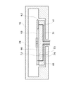
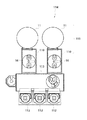
図7は、図6の基板ハンドリング機構60を内包する搬送室15の概略構成を示す断面図である。
【0070】
図7において、搬送室15は、その内部の上方に第1アーム部63、第2アーム部66及び拘持部68が回転移動可能な移動空間70を有し、該移動空間70は搬送室15の側壁部に配設された開口部(不図示)を介して基板処理装置11やウエハ搬出入室14の内部空間と接続される。また、搬送室15は、その内部の下方に回転部61及び環状回転部65を収容する収容空間71を有し、該収容空間71はクラスタ基板処理システム10の上下方向に沿った中心軸を有する円柱状の空間である。環状回転部65の外径は、収容空間71の直径より若干小さく設定されるので、環状回転部65の中心軸が収容空間71の中心軸と一致するように、環状回転部65が収容空間71に収容され、且つ回転部61が環状回転部65に収容されたとき、回転部61及び環状回転部65は収容空間71の容積をほぼ充填する。このとき、回転部61は円柱状部材であり、環状回転部65は環状部材であるため、それらの半径方向に関する撓み量が小さくなり、上述した開口部の面積の設定において当該撓み量を考慮する必要はない。
【0071】
また、回転部61は中心軸方向に沿って穿孔された排気ポート72を有し、環状回転部65は、回転部61が回転する前のイニシャル状態にあるときにおいて排気ポート72に対応する位置に穿孔された排気ポート73を底部に有し、搬送室15は、環状回転部65が回転する前のイニシャル状態にあるときにおいて排気ポート73に対応する位置に穿孔された排気ポート74を底部に有する。
【0072】
次に、基板ハンドリング機構60の基板搬送方法について図面を用いて説明する。
【0073】
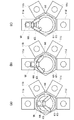
図8は、図7の基板ハンドリング機構60が実行する基板Wの直線方向に関する搬送方法を説明する図である。
【0074】
まず、基板Wを拘持した拘持部68の第1アーム部63及び第2アーム部66に対する位置関係を固定し、第1アーム部63の回転部61に対する位置関係を固定し、さらに、第2アーム部66の環状回転部65に対する位置関係を固定したまま、回転部61及び環状回転部65を同調させて、それらの中心軸回りに所定の角度だけ回転させることにより、基板Wを拘持した拘持部68を、基板Wを搬入すべき基板処理装置11aに正対させる(図8(a))。
【0075】
そして、さらに環状回転部65を反時計回りに所定の回転速度で回転させるとき、第2アーム部66を時計回りに同じ所定の回転速度で回転させると共に、回転部61も時計回りに同じ所定の回転速度で回転させる。このとき、拘持部68は第1アーム部63の拘持部68に対する回転角と、第2アーム部66の拘持部68に対する回転角とを整合する後述の整合構造100を有するため、拘持部68は基板処理装置11aへ直線状に移動する(図8(b))。そして、基板処理装置11aの内部へ進入した拘持部68が所望の位置に到達したとき、環状回転部65、第2アーム部66及び回転部61の回転を中止することによって基板Wを基板処理装置11aにおける所望の位置へ搬送する(図8(c))。
【0076】
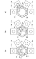
図9は、図7の基板ハンドリング機構60が実行する基板Wの方向変換を伴う搬送方法を説明する図である。
【0077】
まず、図8の直線方向に関する搬送方法の手順を逆に実行することにより、基板処理装置11aにおいて処理の終了した基板Wを搬出し(図9(a))、その後、基板Wを拘持した拘持部68の第1アーム部63及び第2アーム部66に対する位置関係を固定し、第1アーム部63の回転部61に対する位置関係を固定し、さらに、第2アーム部66の環状回転部65に対する位置関係を固定したまま、回転部61及び環状回転部65を同調させて、それらの中心軸回りに所定の角度だけ回転させることにより、基板Wを拘持した拘持部68を、基板Wを搬入すべき基板処理装置11bに正対させる(図9(b))。
【0078】
そして、図8の直線方向に関する搬送方法の手順を実行することによって基板Wを基板処理装置11bにおける所望の位置に搬送する(図9(c))。
【0079】
図10は、図6における拘持部68が有する第1アーム部63の回転角及び第2アーム部66の回転角を整合する整合構造100の概略構成を示す平面図である。
【0080】
図10(a)において、拘持部68は、第1アーム部63の他端に固定され、拘持部68に遊合される第1のギヤ101と、第2アーム部66の他端に固定され、拘持部68に遊合される第2のギヤ102と、第1のギヤ101及び第2のギヤ102にたすき掛け状に掛けられた駆動チェーン103とを備える。
【0081】
第2アーム部66の回転に応じて第2のギヤ102が所定の角度だけ回転するとき、当該所定の角度に対応した移動量だけ駆動チェーン103は移動し、当該移動量に対応して第1のギヤ101は回転する。このとき、第2のギヤ102と第1のギヤ101の有効径は同じであるので、第1のギヤ101は、第2のギヤ102と同じ所定の角度だけ回転する。これにより、拘持部68は第1アーム部63の回転角及び第2アーム部66の回転角を整合する。
【0082】
整合構造100の構成は上述したものに限られず、図10(b)に示すように、第1アーム部63の他端に固定され、拘持部68に遊合される円筒形磁石104と、第2アーム部66の他端に固定され、拘持部68に遊合される円筒形磁石105とを備えてもよく、このとき、円筒形磁石104及び円筒形磁石105の各々は、N極とS極が周方向に同じピッチで交互に配列され、円筒形磁石104における磁極と、当該極に対向する円筒形磁石105における磁極が反対極であるように配設される。
【0083】
ここで、第2アーム部66の回転に応じて円筒形磁石105が所定の角度だけ回転するとき、反対極同士の磁力によって円筒形磁石104は所定の角度だけ回転する。これにより、拘持部68は第1アーム部63の回転角及び第2アーム部66の回転角を整合する。
【0084】
本発明の第2の実施の形態によれば、第1レッグ部64における回転部61は、中心部が搬送室15に回転自在に接続された円柱体から成り、回転部61の半径は、その中心部から延伸部62の他端までの距離よりも小さく、且つ第2レッグ部67における環状回転部65は、回転部61の中心軸に沿って配設された環状体であり、環状回転部65が収容空間71に収容され、且つ回転部61が環状回転部65に収容されたとき、回転部61及び環状回転部65は収容空間71の容積をほぼ充填するので、搬送室15内部の空間容積が小さくなり、回転部61及び環状回転部65の回転による気流の乱れの発生を防止できると共に、回転部61及び環状回転部65における剛性の向上によって撓み量が小さくなり、搬送室15の開口部の面積を小さくできる。その結果、パーティクル等の巻き上げや進入を防止でき、もってパーティクル等の基板への付着を防止できる。また、搬送室15内部の空間容積が小さくなるため、搬送室15内部の真空化を迅速に実行することができ、もってスループットを向上できる。
【0085】
また、第1レッグ部64における第1アーム部63の一端の回転軸から回転部61の中心部までの距離は、第2レッグ部67における第2アーム部66の一端の回転軸から環状回転部65の中心部までの距離と等しいので、回転部61と環状回転部65の回転角度を揃えれば、第1レッグ部64及び第2レッグ部67の動作を同調させることができ、基板Wを正確に所望の位置に搬送できる。
【0086】
さらに、第1レッグ部64及び第2レッグ部67の各々を、第1アーム部63及び第2アーム部66の他端において互いに接続する拘持部68を備えるので、第1レッグ部64及び第2レッグ部67の動作をより正確に同調させることができ、基板Wをより正確に所望の位置に搬送できる。
【0087】
拘持部68は、第1アーム部63の他端に固定され、拘持部68に遊合される第1のギヤ101と、第2アーム部66の他端に固定され、拘持部68に遊合される第2のギヤ102と、第1のギヤ101及び第2のギヤ102にたすき掛け状に掛けられた駆動チェーン103とを備える整合構造100を有するので、第1レッグ部64及び第2レッグ部67の動作をさらに正確に同調させることができ、基板Wをさらに正確に所望の位置に搬送できる。
【0088】
また、回転部61は中心軸方向に沿って穿孔された排気ポート72を有し、環状回転部65は、回転部61が回転する前のイニシャル状態にあるときにおいて排気ポート72に対応する位置に穿孔された排気ポート73を底部に有し、搬送室15は、環状回転部65が回転する前のイニシャル状態にあるときにおいて排気ポート73に対応する位置に穿孔された排気ポート74を底部に有するので、排気ポート72、排気ポート73及び排気ポート74を介して搬送室15内部の気体排出の効率を向上することができ、もってスループットをさらに向上できる。
【0089】
上述した基板ハンドリング機構60において、回転部61には、その中心軸に沿った円柱孔が穿孔されていてもよく、これにより、回転部61を軽量化でき、もって慣性モーメントを低減できる。その結果、基板Wの搬送速度を向上でき、よりスループットを向上できる。
【0090】
上述した基板ハンドリング機構16や基板ハンドリング機構60を使用する基板処理システムは、クラスタ基板処理システム10に限られず、例えば、図11に示すような基板処理装置11及び該基板処理装置11に基板Wを受け渡しするロードロック室110から構成される2つのプロセスモジュール111と、3つのウエハカセット112と、矩形状の共通搬送路であるトランスファチャンバ113とを備え、2つのプロセスモジュール111が互いに平行に配設され、2つのプロセスモジュール111の各々はロードロック室110を介して接続する基板処理システム114であってもよく、この基板処理システム114では、ロードロック室110の各々が基板ハンドリング機構16等をその内部に有する。
【0091】
また、上述した基板ハンドリング機構16の各構成部品や基板ハンドリング機構60の各構成部品の材料は、アルミ合金であってもよく、これにより、基板ハンドリング機構16及び基板ハンドリング機構60の重量を削減することができ、もって慣性モーメントを低減できる。その結果、基板Wの搬送速度を向上でき、よりスループットを向上できる。さらに、アルミ合金が有する耐腐食性により、基板ハンドリング機構16及び基板ハンドリング機構60のメンテナンスサイクル、ひいてはクラスタ基板処理システム10のメンテナンスサイクルを長期化できる。
【0092】
【発明の効果】
以上詳細に説明したように、請求項1記載の搬送装置によれば、少なくとも2つの腕部材を備えると共に筐体内部に配設された基板の搬送装置において、腕部材の一方は、中心部が筐体に回転自在に接続された円柱体から成り、円柱体の半径は中心部から一端までの距離よりも大きいので、筐体内部の空間容積が小さくなり、腕部材の一方の回転による気流の乱れの発生を防止できると共に、腕部材の一方における剛性の向上によって撓み量が小さくなり、筐体における腕部材用の開口部の面積を小さくできる。その結果、パーティクル等の巻き上げや進入を防止でき、もってパーティクル等の基板への付着を防止できる。また、筐体内部の空間容積が小さくなるため、筐体内部の真空化を迅速に実行することができ、もってスループットを向上できる。
【0093】
請求項2記載の搬送装置によれば、筐体は円柱状の腕部材収容孔を備え、該腕部材収容孔は前記円柱体を収容するので、筐体内部の空間容積がより小さくなり、もってパーティクル等の基板への付着を確実に防止できる。
【0094】
請求項3記載の搬送装置によれば、腕部材収容孔の直径は、円柱体の直径とほぼ一致するので、筐体内部の空間容積がさらに小さくなり、もってパーティクル等の基板への付着をより確実に防止できる。
【0095】
請求項4記載の搬送装置によれば、腕部材の一方である円柱体は中心軸方向に沿って穿孔された貫通孔を有し、筐体は貫通孔に対応する位置に穿孔された他の貫通孔を有するので、当該貫通孔及び他の貫通孔を介して筐体内部の気体排出の効率を向上することができ、もってスループットをさらに向上できる。
【0096】
請求項5記載の搬送装置によれば、腕部材の一方である円柱体にはその中心軸に沿った円柱孔が穿孔されているので、腕部材の一方を軽量化でき、もって慣性モーメントを低減できる。その結果、基板の搬送速度を向上でき、よりスループットを向上できる。
【0097】
請求項6記載の搬送装置によれば、少なくとも2つの腕部材から成る2つの屈折構造を備えると共に筐体内部に配設された基板の搬送装置では、屈折構造の一方における腕部材の一方は、中心部が筐体に回転自在に接続された円柱体から成り、円柱体の半径は中心部から腕部材の他方の一端までの距離よりも小さく、且つ屈折構造の他方における腕部材の一方は、円柱体の中心軸に沿って配設された環状体であるので、筐体内部の空間容積が小さくなり、腕部材の一方の回転による気流の乱れの発生を防止できると共に、腕部材の一方における剛性の向上によって撓み量が小さくなり、筐体の開口部の面積を小さくできる。その結果、パーティクル等の巻き上げや進入を防止でき、もってパーティクル等の基板への付着を防止できる。また、筐体内部の空間容積が小さくなるため、筐体内部の真空化を迅速に実行することができ、もってスループットを向上できる。
【0098】
請求項7記載の搬送装置によれば、筐体は円柱状の腕部材収容孔を備え、該腕部材収容孔は前記環状体を収容するので、筐体内部の空間容積がより小さくなり、もってパーティクル等の基板への付着を確実に防止できる。
【0099】
請求項8記載の搬送装置によれば、腕部材収容孔の直径は、環状体の外径とほぼ一致するので、筐体内部の空間容積がさらに小さくなり、もってパーティクル等の基板への付着をより確実に防止できる。
【0100】
請求項9記載の搬送装置によれば、屈折構造の一方の腕部材の一方における腕部材の他方に対する回転軸から中心部までの距離は、屈折構造の他方の腕部材の一方における腕部材の他方に対する回転軸から中心部までの距離と等しいので、円柱体と環状体の回転角度を揃えれば、屈折構造の動作を同調させることができ、基板を正確に所望の位置に搬送できる。
【0101】
請求項10記載の搬送装置によれば、屈折構造の各々を、腕部材の他方の他端において互いに接続する基板拘持部を備えるので、屈折構造の動作をより正確に同調させることができ、基板をより正確に所望の位置に搬送できる。
【0102】
請求項11記載の搬送装置によれば、基板拘持部は、屈折構造の一方における腕部材の他方の回転角と、屈折構造の他方における腕部材の他方の回転角とを整合する整合構造を有するので、屈折構造の動作をさらに正確に同調させることができ、基板をさらに正確に所望の位置に搬送できる。
【0103】
請求項12記載の搬送装置によれば、円柱体は中心軸方向に沿って穿孔された貫通孔を有し、環状体は貫通孔に対応する位置に穿孔された他の貫通孔を有し、且つ筐体は他の貫通孔に対応する位置に穿孔されたさらに他の貫通孔を有するので、当該貫通孔、他の貫通孔及びさらに他の貫通孔を介して筐体内部の気体排出の効率を向上することができ、もってスループットをさらに向上できる。
【0104】
請求項13記載の搬送装置によれば、屈折構造の一方における腕部材の一方を軽量化でき、もって慣性モーメントを低減できる。その結果、基板の搬送速度を向上でき、よりスループットを向上できる。
【図面の簡単な説明】
【図1】本発明の第1の実施の形態に係る搬送装置が配設されたクラスタ基板処理システムの概略構成を示す平面図である。
【図2】図1のクラスタ基板処理システム10における基板ハンドリング機構16の概略構成を示す斜視図である。
【図3】図2の基板ハンドリング機構16を内包する搬送室15の概略構成を示す断面図である。
【図4】図2の基板ハンドリング機構16が実行する基板Wの直線方向に関する搬送方法を説明する図である。
【図5】図2の基板ハンドリング機構16が実行する基板Wの方向変換を伴う搬送方法を説明する図である。
【図6】本発明の第2の実施の形態に係る搬送装置の概略構成を示す斜視図である。
【図7】図6の基板ハンドリング機構60を内包する搬送室15の概略構成を示す断面図である。
【図8】図7の基板ハンドリング機構60が実行する基板Wの直線方向に関する搬送方法を説明する図である。
【図9】図7の基板ハンドリング機構60が実行する基板Wの方向変換を伴う搬送方法を説明する図である。
【図10】図6における拘持部68が有する第1アーム部63の回転角及び第2アーム部66の回転角を整合する整合構造100の概略構成を示す平面図である。
【図11】基板ハンドリング機構16を使用する他の基板処理システム114の概略構成を示す平面図である。
【図12】スカラアーム式ハンドリング機構が配設された従来のクラスタ基板処理システムの概略構成を示す平面図である。
【図13】図12におけるスカラアーム式ハンドリング機構125の概略構成を示す斜視図である。
【図14】フロッグレッグ式ハンドリング機構が配設された従来のクラスタ基板処理システムの概略構成を示す平面図である。
【図15】図13のスカラアーム式ハンドリング機構125を内包する搬送室124の概略構成を示す断面図である。
【符号の説明】
10 クラスタ基板処理システム
11 基板処理装置
14 ウエハ搬出入室
15 搬送室
16,60 基板ハンドリング機構
20,61 回転部
21 アーム部
22 拘持部
31 開口部
32,71 収容空間
63 第1アーム部
64 第1レッグ部
65 環状回転部
66 第2アーム部
67 第2レッグ部
68 拘持部
33,34,72,73,74 排気ポート
100 整合構造[0001]
[Industrial applications]
The present invention relates to an apparatus for transporting a substrate, particularly an apparatus for transporting a substrate such as a semiconductor wafer.
[0002]
[Prior art]
Conventionally, as a substrate processing system for performing various processes such as ion doping, film formation, and etching on a substrate W such as a semiconductor wafer, a plurality of substrate processing apparatuses that perform the same process or different processes for the purpose of improving throughput and yield have been developed. There is known a cluster substrate processing system in which a plurality of substrate processing apparatuses are radially arranged via a common transfer chamber.
[0003]
In this cluster substrate processing system, a transfer mechanism for transferring the substrate W is provided in the transfer chamber in order to exchange the processed substrate W and the unprocessed substrate W in each substrate processing apparatus. As representative examples of such a transport mechanism, a scalar arm type handling mechanism and a frog leg type handling mechanism described below are known (for example, see Patent Document 1).
[0004]
FIG. 12 is a plan view showing a schematic configuration of a conventional cluster substrate processing system provided with a SCARA arm type handling mechanism.
[0005]
12, a cluster substrate processing system 120 includes two substrate processing apparatuses 121 for processing a substrate W therein, a load lock chamber 122 for loading and unloading a substrate W from a wafer cassette (not shown), and a load lock chamber 122. And a transfer chamber 124 for connecting the substrate processing apparatus 121 and the wafer transfer chamber 123. The transfer chamber 124 includes a transfer chamber 124 for connecting the substrate processing apparatus 121 and the wafer transfer chamber 123. A SCARA arm type handling mechanism 125 is provided therein.
[0006]
As shown in FIG. 13, the SCARA arm type handling mechanism 125 includes a rod-shaped first arm 130, a rod-shaped second arm 131, and a retaining part 132 for retaining the substrate W. Is connected to the floor of the transfer chamber 124 at one end so as to be rotatable when the cluster substrate processing system 120 is viewed from above, and the second arm 131 is connected to the first arm 130 at one end. The holding section 132 is rotatably connected to the other end, and is connected to the other end of the second arm section 131.
[0007]
When the substrate W is transported by the SCARA arm type handling mechanism 125, the first arm 130, the second arm 131, and the holding unit 132 cooperate to transfer the substrate W to a desired position in the substrate processing apparatus 121 or the wafer loading / unloading chamber 123. Move in and out of the location.
[0008]
FIG. 14 is a plan view showing a schematic configuration of a conventional cluster substrate processing system provided with a frog leg type handling mechanism.
[0009]
In FIG. 14, a cluster substrate processing system 140 includes four substrate processing apparatuses 141 for processing a substrate W therein, and loading or unloading of a substrate W from a load lock chamber (not shown). And a transfer chamber 143 connecting the substrate processing apparatus 141 and the wafer transfer chamber 142. The transfer chamber 143 has a frog-leg type handling mechanism 144 therein.
[0010]
The frog-leg-type handling mechanism 144 includes a column-shaped base 145 erected perpendicularly to the floor of the transfer chamber 143, a first arm 146 including two rod-shaped members arranged in parallel, and a rod-shaped second The first arm 146 is connected to the side surface of the base 145 at one end thereof so as to be movable in the circumferential direction at one end thereof. The first arm 146 includes two frog legs 148 formed by the arm 147 and a holding unit 149 for holding the substrate W. The second arm 147 is rotatably connected at one end thereof to the other end of the first arm 146, and the engaging portion 149 is connected to the other end of the second arm 147.
[0011]
When the substrate W is transported by the frog leg type handling mechanism 144, the first arm 146, the second arm 147, and the holding unit 149 cooperate to transfer the substrate W to a desired position in the substrate processing apparatus 141 or the wafer loading / unloading chamber 142. Move in and out of the location.
[0012]
[Patent Document 1]
JP-A-10-154739 (FIGS. 1 and 3)
[0013]
[Problems to be solved by the invention]
However, as shown in FIG. 15, in the transfer chamber 124 in the cluster substrate processing system 120, the space 150 in which the first arm unit 130 rotates and moves can not be provided with an interference object, and thus the transfer chamber 124 is not provided. There is a tendency for the space volume inside 124 to be large. When the substrate W is loaded into the substrate processing apparatus 121, the pressure inside the transfer chamber 124 is reduced in order to maintain the degree of vacuum inside the substrate processing apparatus 121, but the inside of the transfer chamber 124 is completely evacuated. Is difficult and some gas remains.
[0014]
At this time, as described above, when the space volume inside the transfer chamber 124 becomes large, the first arm 130 rotates to generate turbulence in the airflow in the space 150, and particles and the like are wound up. There is a problem that particles and the like adhere to the substrate W.
[0015]
Further, since the first arm portion 130 has a rod shape, the amount of deflection in the longitudinal direction tends to be large. When the amount of deflection is large in this manner, the positional accuracy of the second arm portion 131 and the holding portion 132 is deteriorated, and there is a possibility that the substrate W may interfere with the housing of the transfer chamber 124 when the substrate W is transferred. It is necessary to increase the area of the opening 151. However, if the area of the opening of the opening 151 is increased, the penetration of particles and the like from the outside becomes easy, and as a result, the entered particles and the like adhere to the substrate W. was there.
[0016]
These problems also occur in the cluster substrate processing system 140 provided with the frog-leg type handling mechanism 144.
[0017]
An object of the present invention is to provide a transport device that can prevent particles and the like from adhering to a substrate.
[0018]
[Means for Solving the Problems]
In order to achieve the above object, a substrate transport apparatus according to claim 1, further comprising at least two arm members for supporting the substrate and disposed inside a predetermined housing, and one of the arm members is one end thereof. In the substrate transfer device rotatably connected to the other of the arm members, one of the arm members is formed of a column having a center portion rotatably connected to the housing, and a radius of the column is , And is larger than the distance from the center to the one end.
[0019]
According to the transfer device of the first aspect, in the transfer device for a substrate provided with at least two arm members and disposed inside the housing, one of the arm members has a center portion rotatably connected to the housing. Since the radius of the cylindrical body is larger than the distance from the center to one end, the space volume inside the housing is reduced, and the occurrence of turbulence in the air flow due to one rotation of the arm member can be prevented, The amount of deflection is reduced by improving the rigidity of one of the arm members, and the area of the opening for the arm member in the housing can be reduced. As a result, it is possible to prevent the particles and the like from winding up and entering, and thus prevent the particles and the like from adhering to the substrate. In addition, since the space volume inside the housing is reduced, the inside of the housing can be quickly evacuated, and the throughput can be improved.
[0020]
According to a second aspect of the present invention, in the transport apparatus of the first aspect, the housing includes a cylindrical arm member receiving hole, and the arm member receiving hole receives the cylindrical body. .
[0021]
According to the transfer device of the second aspect, the housing has the columnar arm member receiving hole, and the arm member receiving hole stores the columnar body. Particles and the like can be reliably prevented from adhering to the substrate.
[0022]
According to a third aspect of the present invention, the diameter of the arm member receiving hole is substantially equal to the diameter of the cylindrical body.
[0023]
According to the third aspect of the present invention, since the diameter of the arm member accommodating hole is substantially equal to the diameter of the cylindrical body, the space volume inside the housing is further reduced, so that the adhesion of particles or the like to the substrate is further reduced. It can be reliably prevented.
[0024]
According to a fourth aspect of the present invention, in the transporting apparatus according to any one of the first to third aspects, the cylindrical body has a through-hole that is bored along a central axis direction, and the casing is configured to be the housing. It is characterized by having another through hole drilled at a position corresponding to the through hole.
[0025]
According to the transport device of the fourth aspect, the cylindrical body, which is one of the arm members, has a through-hole perforated along the central axis direction, and the housing has another perforated hole corresponding to the through-hole. Since the through holes are provided, the efficiency of gas discharge inside the housing can be improved through the through holes and other through holes, thereby further improving the throughput.
[0026]
According to a fifth aspect of the present invention, there is provided the transporting apparatus according to any one of the first to fourth aspects, wherein the cylindrical body is provided with a cylindrical hole along a central axis thereof. .
[0027]
According to the transfer device of the fifth aspect, since the cylindrical body which is one of the arm members is formed with the cylindrical hole along the central axis thereof, one of the arm members can be reduced in weight, thereby reducing the moment of inertia. it can. As a result, the substrate transfer speed can be improved, and the throughput can be further improved.
[0028]
In order to achieve the above object, the transfer device according to claim 6 includes at least two arm members for supporting a substrate and is disposed inside a housing, and one of the arm members is provided at one end of the arm member. In a substrate transport apparatus provided with at least two bending structures rotatably connected to the other end of the arm, one of the arm members in one of the bending structures has a center portion rotatably connected to the housing. A radius of the cylindrical body is smaller than a distance from the center to the other end of the arm member, and one of the arm members on the other side of the bending structure has a central axis of the cylindrical body. Characterized in that it is an annular body disposed along.
[0029]
According to the transfer device of the sixth aspect, in the transfer device for a substrate provided with two bending structures including at least two arm members and disposed inside the housing, one of the arm members in one of the bending structures includes: The central portion is composed of a cylindrical body rotatably connected to the housing, the radius of the cylindrical body is smaller than the distance from the central portion to the other end of the arm member, and one of the arm members in the other of the bending structure is Since the annular body is arranged along the center axis of the cylindrical body, the space volume inside the housing is reduced, and the occurrence of turbulence in the air flow due to the rotation of one of the arm members can be prevented. The improvement in rigidity reduces the amount of deflection, and can reduce the area of the opening of the housing. As a result, it is possible to prevent the particles and the like from winding up and entering, and thus prevent the particles and the like from adhering to the substrate. In addition, since the space volume inside the housing is reduced, the inside of the housing can be quickly evacuated, and the throughput can be improved.
[0030]
According to a seventh aspect of the present invention, there is provided the transport device according to the sixth aspect, wherein the housing includes a columnar arm member receiving hole, and the arm member receiving hole receives the annular body. .
[0031]
According to the transfer device of the seventh aspect, the housing has the columnar arm member housing hole, and the arm member housing hole houses the annular body, so that the space volume inside the housing becomes smaller. Particles and the like can be reliably prevented from adhering to the substrate.
[0032]
According to an eighth aspect of the present invention, in the transporting apparatus according to the seventh aspect, a diameter of the arm member accommodating hole is substantially equal to an outer diameter of the annular body.
[0033]
According to the transfer device of the eighth aspect, the diameter of the arm member accommodating hole substantially coincides with the outer diameter of the annular body, so that the space volume inside the housing is further reduced, so that particles such as particles adhere to the substrate. It can be prevented more reliably.
[0034]
The transfer device according to claim 9, wherein, in the transfer device according to any one of claims 6 to 8, the central portion is located between a rotation axis of one of the arm members of the bending structure with respect to the other of the arm members. A distance from the axis of rotation of one of the arm members of the refraction structure to the other of the arm members with respect to the other of the arm members is equal to a distance from the rotation axis to the central portion.
[0035]
According to the conveying device of the ninth aspect, the distance from the rotation axis to the center of the one arm member of the bending structure with respect to the other of the arm members is the other of the arm members of one of the other arm members of the bending structure. Therefore, if the rotation angles of the cylindrical body and the annular body are equalized, the operation of the refraction structure can be synchronized, and the substrate can be accurately transferred to a desired position.
[0036]
According to a tenth aspect, in the transport apparatus according to any one of the sixth to ninth aspects, the transport device according to any one of the sixth to ninth aspects, further comprising: It is characterized by having.
[0037]
According to the transfer device of claim 10, since each of the bending structures is provided with the board holding portions connected to each other at the other end of the arm member, the operation of the bending structure can be more accurately tuned, The substrate can be transported to a desired position more accurately.
[0038]
The transfer device according to claim 11, wherein the substrate holding unit is configured such that the substrate holding unit includes the other rotation angle of the arm member in one of the bending structures and the arm member in the other of the bending structures. A matching structure for matching the other rotation angle with the other.
[0039]
According to the transfer device of the eleventh aspect, the substrate holding unit has an alignment structure that matches the other rotation angle of the arm member on one of the bending structures with the other rotation angle of the arm member on the other of the bending structures. With this arrangement, the operation of the refraction structure can be more precisely tuned, and the substrate can be transported to a desired position more accurately.
[0040]
The transport device according to claim 12 is the transport device according to any one of claims 6 to 11, wherein the cylindrical body has a through-hole perforated along a central axis direction, and the annular body is It is characterized by having another through-hole drilled at a position corresponding to the through-hole, and the housing further has another through-hole drilled at a position corresponding to the other through-hole.
[0041]
According to the transfer device of claim 12, the cylindrical body has a through-hole perforated along the central axis direction, and the annular body has another through-hole perforated at a position corresponding to the through-hole, In addition, since the housing has still another through-hole perforated at a position corresponding to the other through-hole, the efficiency of gas discharge inside the housing through the through-hole, the other through-hole, and the further through-hole. Can be improved, and the throughput can be further improved.
[0042]
According to a thirteenth aspect of the present invention, in the transporting device according to any one of the sixth to twelfth aspects, the cylindrical body is provided with a cylindrical hole along a central axis thereof. .
[0043]
According to the transport device of the thirteenth aspect, one of the arm members in one of the bending structures can be reduced in weight, and thus the moment of inertia can be reduced. As a result, the substrate transfer speed can be improved, and the throughput can be further improved.
[0044]
BEST MODE FOR CARRYING OUT THE INVENTION
Hereinafter, the transport device according to the first embodiment of the present invention will be described in detail.
[0045]
FIG. 1 is a plan view showing a schematic configuration of a cluster substrate processing system provided with a transfer device according to a first embodiment of the present invention.
[0046]
1, a cluster substrate processing system 10 includes four substrate processing apparatuses 11 for processing substrates W therein, a load lock chamber 13 for loading and unloading substrates W from a wafer cassette 12 storing the substrates W, and a load lock. It has two wafer loading / unloading chambers 14 for loading / unloading the substrate W from / into the load lock chamber 13 and a transfer chamber 15 for connecting the substrate processing apparatus 11 and the wafer loading / unloading chamber 14. Further, the cluster substrate processing system 10 has a substrate handling mechanism 16 inside the transfer chamber 15. The substrate handling mechanism 16 carries the substrate W into and out of the wafer loading / unloading chamber 14 and the substrate processing apparatus 11.
[0047]
FIG. 2 is a perspective view showing a schematic configuration of the substrate handling mechanism 16 in the cluster substrate processing system 10 of FIG.
[0048]
In FIG. 2, the substrate handling mechanism 16 includes a rotating unit 20 that is a cylindrical body, an arm unit 21 that is a rod body, and a holding unit 22 that holds the substrate W. The rotating unit 20 includes the cluster substrate processing system 10. When viewed from above, the center portion of the arm portion 21 is rotatably connected to the floor surface of the transfer chamber 15, and the arm portion 21 is rotatably connected at one end to the vicinity of the outer edge of the rotating portion 20. Is rotatably connected to the other end of the arm 21. The radius of the rotating part 20 is larger than the distance from the center of the rotating part 20 to the rotation axis of the arm 21 with respect to the rotating part 20. When the substrate W is transported by the substrate handling mechanism 16, the rotating unit 20, the arm unit 21, and the holding unit 22 cooperate to carry the substrate W into and out of a desired position in the substrate processing apparatus 11 and the wafer loading / unloading chamber 14. I do.
[0049]
FIG. 3 is a sectional view showing a schematic configuration of the transfer chamber 15 containing the substrate handling mechanism 16 of FIG.
[0050]
In FIG. 3, the transfer chamber 15 has a movable space 30 in which the arm unit 21 and the holding unit 22 can rotate and move above the inside thereof, and the movable space 30 is disposed on a side wall of the transfer chamber 15. It is connected to the substrate processing apparatus 11 and the internal space of the wafer loading / unloading chamber 14 through the opening 31. The transfer chamber 15 has an accommodation space 32 for accommodating the rotating part 20 below the inside thereof. The accommodation space 32 is a columnar space having a central axis along the vertical direction of the cluster substrate processing system 10. is there. Since the diameter of the rotating part 20 is set slightly smaller than the diameter of the housing space 32, the rotating part 20 is housed in the housing space 32 so that the center axis of the rotating part 20 coincides with the center axis of the housing space 32. At this time, the rotating unit 20 substantially fills the volume of the storage space 32. At this time, since the rotating portion 20 is not a rod-shaped member but a columnar member, the amount of bending in the radial direction is small, and it is not necessary to consider the amount of bending in setting the area of the opening 31.
[0051]
In addition, the rotating unit 20 has an exhaust port 33 pierced along the center axis direction, and the transfer chamber 15 is pierced at a position corresponding to the exhaust port 33 in the initial state before the rotating unit 20 rotates. The exhaust port 34 is provided at the bottom.
[0052]
Next, a substrate transporting method of the substrate handling mechanism 16 will be described with reference to the drawings.
[0053]
FIG. 4 is a diagram illustrating a method of transporting the substrate W in the linear direction performed by the substrate handling mechanism 16 of FIG.
[0054]
First, while the positional relationship of the holding unit 22 holding the substrate W to the arm unit 21 is fixed, and the positional relationship of the arm unit 21 to the rotating unit 20 is fixed, the rotating unit 20 is moved around a predetermined central axis. By rotating the holding unit 22 by the angle, the holding unit 22 is directly opposed to the substrate processing apparatus 11a to which the substrate W is to be carried in (FIG. 4A).
[0055]
When the rotating unit 20 is further rotated counterclockwise at a predetermined rotation speed, the arm unit 21 is rotated clockwise at the same predetermined rotation speed, so that the holding unit 22 is linearly moved to the substrate processing apparatus 11a. (FIG. 4B), and when the engaging unit 22 that has entered the inside of the substrate processing apparatus 11a reaches a desired position, the rotation of the rotating unit 20 and the arm unit 21 is stopped, thereby removing the substrate W. The substrate is transported to a desired position in the substrate processing apparatus 11a (FIG. 4C).
[0056]
FIG. 5 is a view for explaining a transfer method involving the direction change of the substrate W performed by the substrate handling mechanism 16 of FIG.
[0057]
First, by carrying out the procedure of the transfer method in the linear direction in FIG. 4 in reverse, the substrate W that has been processed in the substrate processing apparatus 11a is unloaded (FIG. 5A), and then the substrate W is held. By rotating the rotating unit 20 by a predetermined angle around its center axis while fixing the positional relationship of the holding unit 22 to the arm unit 21 and fixing the positional relationship of the arm unit 21 to the rotating unit 20, the substrate The holding unit 22 holding W is directly opposed to the substrate processing apparatus 11b to which the substrate W is to be carried in (FIG. 5B).
[0058]
Then, the substrate W is transferred to a desired position in the substrate processing apparatus 11b by executing the procedure of the transfer method in the linear direction in FIG. 4 (FIG. 5C).
[0059]
According to the first embodiment of the present invention, the rotating unit 20 is formed of a cylindrical body whose center is rotatably connected to the transfer chamber 15, and the radius of the rotating unit 20 is set to be equal to the center of the rotating unit 20. When the rotation unit 20 is accommodated in the accommodation space 32, the rotation unit 20 substantially fills the volume of the accommodation space 32, and is larger than the distance between the rotation unit 20 and the rotation axis of the arm unit 21. The space volume is reduced, and the turbulence of the airflow due to the rotation of the rotating unit 20 can be prevented. In addition, the rigidity of the rotating unit 20 can reduce the amount of bending in the radial direction, thereby reducing the area of the opening of the transfer chamber 15. . As a result, it is possible to prevent the particles and the like from winding up and entering, and thus prevent the particles and the like from adhering to the substrate. Further, since the space volume inside the transfer chamber 15 is reduced, the inside of the transfer chamber 15 can be quickly evacuated, and the throughput can be improved.
[0060]
In addition, the rotating unit 20 has an exhaust port 33 that is perforated along the center axis direction, and the transfer chamber 15 is perforated at a position corresponding to the exhaust port 33 when in an initial state before the rotating unit 20 rotates. Since the exhaust port 34 is provided at the bottom, the efficiency of exhausting gas from the transfer chamber 15 through the exhaust port 33 and the exhaust port 34 can be improved, and the throughput can be further improved.
[0061]
In the substrate handling mechanism 16 described above, the rotating portion 20 may be provided with a cylindrical hole along the central axis thereof, whereby the weight of the rotating portion 20 can be reduced and the moment of inertia can be reduced. As a result, the transfer speed of the substrate W can be improved, and the throughput can be further improved.
[0062]
Next, a transport device according to a second embodiment of the present invention will be described in detail.
[0063]
The transfer apparatus according to the second embodiment of the present invention is also disposed inside the transfer chamber 15 in the cluster substrate processing system 10, similarly to the above-described substrate handling mechanism 16.
[0064]
FIG. 6 is a perspective view illustrating a schematic configuration of a transport device according to the second embodiment of the present invention.
[0065]
In FIG. 6, the substrate handling mechanism 60 is a ring-shaped body, a first leg part 64 including a rotating part 61 that is a cylindrical body, an extending part 62 that is a plate-shaped body, and a first arm part 63 that is a rod-shaped body. A second leg portion 67 including an annular rotating portion 65 and a second arm portion 66 that is a rod-shaped body, and a holding portion 68 for holding the substrate W are provided.
[0066]
The rotating unit 61 is rotatably connected to the floor of the transfer chamber 15 at the center when the cluster substrate processing system 10 is viewed from above, and the annular rotating unit 65 is arranged along the central axis of the rotating unit 61. Is established. In the first leg portion 64, the extension portion 62 is fixed at one end near the outer edge of the rotating portion 61, and the first arm portion 63 is rotatably connected at one end to the other end of the extension portion 62. In the second leg portion 67, the annular rotating portion 65 is rotatably disposed around the central axis of the rotating portion 61, and the second arm portion 66 is rotatably connected at one end to the annular rotating portion 65. Is done. Further, the engaging portion 68 is connected to each of the first arm portion 63 and the second arm portion 66 at the other end.
[0067]
The radius of the rotating portion 61 is smaller than the distance from the center to the other end of the extending portion 62, but the radius of the rotating portion 61 from the rotating shaft at one end of the first arm portion 63 in the first leg portion 64. Is equal to the distance from the rotation axis of one end of the second arm portion 66 in the second leg portion 67 to the center of the annular rotation portion 65.
[0068]
When the substrate W is transported by the handling mechanism 60, the first leg 64, the second leg 67, and the holding unit 68 cooperate to move the substrate W to a desired position in the substrate processing apparatus 11 or the wafer loading / unloading chamber 14. Carry in and out.
[0069]
FIG. 7 is a sectional view showing a schematic configuration of the transfer chamber 15 including the substrate handling mechanism 60 of FIG.
[0070]
In FIG. 7, the transfer chamber 15 has a movable space 70 in which the first arm 63, the second arm 66, and the restraining unit 68 can be rotatably moved. Are connected to the substrate processing apparatus 11 and the internal space of the wafer loading / unloading chamber 14 through an opening (not shown) provided in the side wall of the substrate. Further, the transfer chamber 15 has a housing space 71 for housing the rotating part 61 and the annular rotating part 65 below the inside thereof, and the housing space 71 has a central axis along the vertical direction of the cluster substrate processing system 10. It is a cylindrical space. Since the outer diameter of the annular rotating part 65 is set to be slightly smaller than the diameter of the accommodation space 71, the annular rotating part 65 is adjusted so that the central axis of the annular rotating part 65 coincides with the central axis of the accommodation space 71. When the rotating portion 61 is accommodated in the annular rotating portion 65, the rotating portion 61 and the annular rotating portion 65 substantially fill the volume of the accommodation space 71. At this time, since the rotating portion 61 is a columnar member and the annular rotating portion 65 is an annular member, the amount of bending in the radial direction is small, and the amount of bending is considered in setting the area of the opening described above. No need.
[0071]
The rotating portion 61 has an exhaust port 72 perforated along the central axis direction, and the annular rotating portion 65 is located at a position corresponding to the exhaust port 72 when the rotating portion 61 is in an initial state before rotating. The bottom has a perforated exhaust port 73 at the bottom, and the transfer chamber 15 has at the bottom a perforated exhaust port 74 at a position corresponding to the exhaust port 73 when in the initial state before the annular rotating portion 65 rotates. .
[0072]
Next, a substrate transporting method of the substrate handling mechanism 60 will be described with reference to the drawings.
[0073]
FIG. 8 is a diagram illustrating a method of transporting the substrate W in the linear direction performed by the substrate handling mechanism 60 of FIG.
[0074]
First, the positional relationship between the holding portion 68 holding the substrate W with respect to the first arm portion 63 and the second arm portion 66 is fixed, the positional relationship with respect to the rotating portion 61 of the first arm portion 63 is fixed, and With the positional relationship between the two-arm part 66 and the annular rotating part 65 fixed, the rotating part 61 and the annular rotating part 65 are synchronized and rotated by a predetermined angle around their central axes, thereby holding the substrate W. The restrained portion 68 is directly opposed to the substrate processing apparatus 11a to which the substrate W is to be loaded (FIG. 8A).
[0075]
When further rotating the annular rotating portion 65 counterclockwise at a predetermined rotation speed, the second arm portion 66 is rotated clockwise at the same predetermined rotation speed, and the rotating portion 61 is also clockwise rotated at the same predetermined rotation speed. Rotate at rotational speed. At this time, since the engaging portion 68 has a later-described alignment structure 100 that matches the rotation angle of the first arm portion 63 with respect to the engaging portion 68 and the rotation angle of the second arm portion 66 with respect to the engaging portion 68, The holding section 68 moves linearly to the substrate processing apparatus 11a (FIG. 8B). When the engaging portion 68 that has entered the inside of the substrate processing apparatus 11a reaches a desired position, the rotation of the annular rotating portion 65, the second arm portion 66, and the rotating portion 61 is stopped to process the substrate W. The sheet is transported to a desired position in the device 11a (FIG. 8C).
[0076]
FIG. 9 is a diagram illustrating a transfer method involving the direction change of the substrate W performed by the substrate handling mechanism 60 of FIG.
[0077]
First, by carrying out the procedure of the transfer method in the linear direction in FIG. 8 in reverse, the substrate W that has been processed in the substrate processing apparatus 11a is unloaded (FIG. 9A), and then the substrate W is held. The positional relationship of the engaging portion 68 with respect to the first arm portion 63 and the second arm portion 66 is fixed, the positional relationship of the first arm portion 63 with respect to the rotating portion 61 is fixed, and the annular rotating portion of the second arm portion 66 is further fixed. With the positional relationship with respect to the fixed portion 65 fixed, the rotating portion 61 and the annular rotating portion 65 are synchronized and rotated by a predetermined angle around their central axes, so that the holding portion 68 holding the substrate W W is directly opposed to the substrate processing apparatus 11b to be carried in (FIG. 9B).
[0078]
Then, the substrate W is transferred to a desired position in the substrate processing apparatus 11b by executing the procedure of the transfer method in the linear direction in FIG. 8 (FIG. 9C).
[0079]
FIG. 10 is a plan view showing a schematic configuration of a matching structure 100 that matches the rotation angle of the first arm 63 and the rotation angle of the second arm 66 included in the holding unit 68 in FIG.
[0080]
In FIG. 10A, the holding unit 68 is fixed to the other end of the first arm unit 63, and is connected to the first gear 101, which is engaged with the holding unit 68, and the other end of the second arm unit 66. A second gear 102 is fixed and engaged with the holding portion 68, and a drive chain 103 is hung over the first gear 101 and the second gear 102.
[0081]
When the second gear 102 rotates by a predetermined angle in response to the rotation of the second arm portion 66, the drive chain 103 moves by a moving amount corresponding to the predetermined angle, and the first chain corresponding to the moving amount. Gear 101 rotates. At this time, since the effective diameters of the second gear 102 and the first gear 101 are the same, the first gear 101 rotates by the same predetermined angle as the second gear 102. Thus, the engaging portion 68 matches the rotation angle of the first arm 63 and the rotation angle of the second arm 66.
[0082]
The configuration of the matching structure 100 is not limited to the one described above, and as shown in FIG. 10B, a cylindrical magnet 104 fixed to the other end of the first arm portion 63 and fitted to the holding portion 68, A cylindrical magnet 105 fixed to the other end of the second arm portion 66 and engaged with the holding portion 68 may be provided. At this time, each of the cylindrical magnet 104 and the cylindrical magnet 105 has an N pole And the S pole are alternately arranged at the same pitch in the circumferential direction, and are arranged such that the magnetic pole of the cylindrical magnet 104 and the magnetic pole of the cylindrical magnet 105 facing the pole are opposite poles.
[0083]
Here, when the cylindrical magnet 105 rotates by a predetermined angle in response to the rotation of the second arm portion 66, the cylindrical magnet 104 rotates by a predetermined angle due to the magnetic force between the opposite poles. Thus, the engaging portion 68 matches the rotation angle of the first arm 63 and the rotation angle of the second arm 66.
[0084]
According to the second embodiment of the present invention, the rotating portion 61 of the first leg portion 64 is formed of a cylindrical body whose center is rotatably connected to the transfer chamber 15, and the radius of the rotating portion 61 is The annular rotating portion 65 of the second leg 67 that is smaller than the distance from the center to the other end of the extending portion 62 is an annular body disposed along the central axis of the rotating portion 61. When the rotating space 61 is housed in the annular rotating portion 65 and the rotating portion 61 is housed in the annular rotating portion 65, the rotating portion 61 and the annular rotating portion 65 almost fill the volume of the housing space 71. The volume is reduced, the turbulence of the air flow due to the rotation of the rotating part 61 and the annular rotating part 65 can be prevented, and the rigidity of the rotating part 61 and the annular rotating part 65 is reduced to reduce the amount of bending, and Area of part It can be reduced. As a result, it is possible to prevent the particles and the like from winding up and entering, and thus prevent the particles and the like from adhering to the substrate. Further, since the space volume inside the transfer chamber 15 is reduced, the inside of the transfer chamber 15 can be quickly evacuated, and the throughput can be improved.
[0085]
The distance from the rotation axis at one end of the first arm portion 63 in the first leg portion 64 to the center of the rotation portion 61 is determined by the distance from the rotation axis at one end of the second arm portion 66 in the second leg portion 67 to the annular rotation portion. Since the rotation angle of the rotating part 61 and the annular rotating part 65 is equalized, the operations of the first leg part 64 and the second leg part 67 can be synchronized, and the substrate W can be accurately adjusted. To a desired position.
[0086]
Furthermore, since the first leg portion 64 and the second leg portion 67 are provided with the holding portions 68 connecting each other at the other ends of the first arm portion 63 and the second arm portion 66, the first leg portion 64 and the second leg portion 67 are connected to each other. The operation of the two leg portions 67 can be tuned more accurately, and the substrate W can be transported to a desired position more accurately.
[0087]
The holding portion 68 is fixed to the other end of the first arm portion 63 and is fixed to the other end of the first gear 101 and the second arm portion 66 which is engaged with the holding portion 68. And a drive chain 103 hung over the first gear 101 and the second gear 102, so that the first leg portion 64 and the The operation of the second leg portion 67 can be tuned more accurately, and the substrate W can be transported to a desired position more accurately.
[0088]
The rotating portion 61 has an exhaust port 72 perforated along the central axis direction, and the annular rotating portion 65 is located at a position corresponding to the exhaust port 72 when the rotating portion 61 is in an initial state before rotating. The bottom has a perforated exhaust port 73 at the bottom, and the transfer chamber 15 has at the bottom a perforated exhaust port 74 at a position corresponding to the exhaust port 73 when in the initial state before the rotation of the annular rotating portion 65. Therefore, the efficiency of gas discharge inside the transfer chamber 15 can be improved through the exhaust port 72, the exhaust port 73, and the exhaust port 74, and the throughput can be further improved.
[0089]
In the above-described substrate handling mechanism 60, the rotating portion 61 may be provided with a cylindrical hole along the central axis thereof, whereby the weight of the rotating portion 61 can be reduced, and the moment of inertia can be reduced. As a result, the transfer speed of the substrate W can be improved, and the throughput can be further improved.
[0090]
The substrate processing system using the substrate handling mechanism 16 or the substrate handling mechanism 60 described above is not limited to the cluster substrate processing system 10, and for example, a substrate processing apparatus 11 as shown in FIG. The apparatus includes two process modules 111 including a load lock chamber 110 for transfer, three wafer cassettes 112, and a transfer chamber 113 that is a rectangular common transfer path, and the two process modules 111 are arranged in parallel with each other. Each of the two process modules 111 may be a substrate processing system 114 connected via a load lock chamber 110. In this substrate processing system 114, each of the load lock chambers 110 includes a substrate handling mechanism 16 and the like. Have inside.
[0091]
The material of each component of the substrate handling mechanism 16 and each component of the substrate handling mechanism 60 described above may be an aluminum alloy, thereby reducing the weight of the substrate handling mechanism 16 and the substrate handling mechanism 60. Therefore, the moment of inertia can be reduced. As a result, the transfer speed of the substrate W can be improved, and the throughput can be further improved. Further, due to the corrosion resistance of the aluminum alloy, the maintenance cycle of the substrate handling mechanism 16 and the substrate handling mechanism 60 and the maintenance cycle of the cluster substrate processing system 10 can be extended.
[0092]
【The invention's effect】
As described above in detail, according to the transfer device of claim 1, in the transfer device for a substrate including at least two arm members and disposed inside the housing, one of the arm members has a central portion. It consists of a cylindrical body that is rotatably connected to the housing, and the radius of the cylindrical body is larger than the distance from the center to one end, so the space volume inside the housing is reduced, and the airflow due to one rotation of the arm member is reduced. Disturbance can be prevented, and the amount of bending can be reduced by improving the rigidity of one of the arm members, so that the area of the opening for the arm member in the housing can be reduced. As a result, it is possible to prevent the particles and the like from winding up and entering, and thus prevent the particles and the like from adhering to the substrate. In addition, since the space volume inside the housing is reduced, the inside of the housing can be quickly evacuated, and the throughput can be improved.
[0093]
According to the transfer device of the second aspect, the housing has the columnar arm member receiving hole, and the arm member receiving hole stores the columnar body. Particles and the like can be reliably prevented from adhering to the substrate.
[0094]
According to the third aspect of the present invention, since the diameter of the arm member accommodating hole is substantially equal to the diameter of the cylindrical body, the space volume inside the housing is further reduced, so that the adhesion of particles or the like to the substrate is further reduced. It can be reliably prevented.
[0095]
According to the transport device of the fourth aspect, the cylindrical body, which is one of the arm members, has a through-hole perforated along the central axis direction, and the housing has another perforated hole corresponding to the through-hole. Since the through holes are provided, the efficiency of gas discharge inside the housing can be improved through the through holes and other through holes, thereby further improving the throughput.
[0096]
According to the transfer device of the fifth aspect, since the cylindrical body which is one of the arm members is formed with the cylindrical hole along the central axis thereof, one of the arm members can be reduced in weight, thereby reducing the moment of inertia. it can. As a result, the substrate transfer speed can be improved, and the throughput can be further improved.
[0097]
According to the transfer device of the sixth aspect, in the transfer device for a substrate provided with two bending structures including at least two arm members and disposed inside the housing, one of the arm members in one of the bending structures includes: The central portion is composed of a cylindrical body rotatably connected to the housing, the radius of the cylindrical body is smaller than the distance from the central portion to the other end of the arm member, and one of the arm members in the other of the bending structure is Since the annular body is arranged along the center axis of the cylindrical body, the space volume inside the housing is reduced, and the occurrence of turbulence in the air flow due to the rotation of one of the arm members can be prevented. The improvement in rigidity reduces the amount of deflection, and can reduce the area of the opening of the housing. As a result, it is possible to prevent the particles and the like from winding up and entering, and thus prevent the particles and the like from adhering to the substrate. In addition, since the space volume inside the housing is reduced, the inside of the housing can be quickly evacuated, and the throughput can be improved.
[0098]
According to the transfer device of the seventh aspect, the housing has the columnar arm member housing hole, and the arm member housing hole houses the annular body, so that the space volume inside the housing becomes smaller. Particles and the like can be reliably prevented from adhering to the substrate.
[0099]
According to the transfer device of the eighth aspect, the diameter of the arm member accommodating hole substantially coincides with the outer diameter of the annular body, so that the space volume inside the housing is further reduced, so that particles such as particles adhere to the substrate. It can be prevented more reliably.
[0100]
According to the conveying device of the ninth aspect, the distance from the rotation axis to the center of the one arm member of the bending structure with respect to the other of the arm members is the other of the arm members of one of the other arm members of the bending structure. Therefore, if the rotation angles of the cylindrical body and the annular body are equalized, the operation of the refraction structure can be synchronized, and the substrate can be accurately transferred to a desired position.
[0101]
According to the transfer device of claim 10, since each of the bending structures is provided with the board holding portions connected to each other at the other end of the arm member, the operation of the bending structure can be more accurately tuned, The substrate can be transported to a desired position more accurately.
[0102]
According to the transfer device of the eleventh aspect, the substrate holding unit has an alignment structure that matches the other rotation angle of the arm member on one of the bending structures with the other rotation angle of the arm member on the other of the bending structures. With this arrangement, the operation of the refraction structure can be more precisely tuned, and the substrate can be transported to a desired position more accurately.
[0103]
According to the transfer device of claim 12, the cylindrical body has a through-hole perforated along the central axis direction, and the annular body has another through-hole perforated at a position corresponding to the through-hole, In addition, since the housing has still another through-hole perforated at a position corresponding to the other through-hole, the efficiency of gas discharge inside the housing through the through-hole, the other through-hole, and the further through-hole. Can be improved, and the throughput can be further improved.
[0104]
According to the transport device of the thirteenth aspect, one of the arm members in one of the bending structures can be reduced in weight, and thus the moment of inertia can be reduced. As a result, the substrate transfer speed can be improved, and the throughput can be further improved.
[Brief description of the drawings]
FIG. 1 is a plan view showing a schematic configuration of a cluster substrate processing system provided with a transfer device according to a first embodiment of the present invention.
FIG. 2 is a perspective view showing a schematic configuration of a substrate handling mechanism 16 in the cluster substrate processing system 10 of FIG.
FIG. 3 is a cross-sectional view illustrating a schematic configuration of a transfer chamber 15 including the substrate handling mechanism 16 of FIG.
FIG. 4 is a diagram illustrating a method of transporting a substrate W in a linear direction performed by the substrate handling mechanism 16 of FIG. 2;
FIG. 5 is a diagram illustrating a transfer method involving a change in direction of a substrate W performed by the substrate handling mechanism 16 of FIG. 2;
FIG. 6 is a perspective view illustrating a schematic configuration of a transport device according to a second embodiment of the present invention.
7 is a cross-sectional view illustrating a schematic configuration of a transfer chamber 15 including the substrate handling mechanism 60 of FIG.
8 is a diagram illustrating a method of transporting a substrate W in a linear direction performed by the substrate handling mechanism 60 of FIG.
FIG. 9 is a diagram illustrating a transfer method involving a change in direction of a substrate W performed by the substrate handling mechanism 60 of FIG. 7;
10 is a plan view showing a schematic configuration of a matching structure 100 that matches a rotation angle of a first arm 63 and a rotation angle of a second arm 66 included in the holding unit 68 in FIG.
FIG. 11 is a plan view showing a schematic configuration of another substrate processing system 114 using the substrate handling mechanism 16.
FIG. 12 is a plan view showing a schematic configuration of a conventional cluster substrate processing system provided with a SCARA arm type handling mechanism.
FIG. 13 is a perspective view showing a schematic configuration of a SCARA arm type handling mechanism 125 in FIG.
FIG. 14 is a plan view showing a schematic configuration of a conventional cluster substrate processing system provided with a frog leg type handling mechanism.
FIG. 15 is a cross-sectional view illustrating a schematic configuration of a transfer chamber 124 including the SCARA arm type handling mechanism 125 of FIG.
[Explanation of symbols]
10 Cluster substrate processing system
11 Substrate processing equipment
14 Wafer loading / unloading room
15 transfer room
16,60 Substrate handling mechanism
20,61 rotating part
21 Arm part
22 Detention Department
31 Opening
32,71 accommodation space
63 1st arm
64 1st leg
65 Annular rotating part
66 2nd arm
67 2nd leg
68 Detention Department
33, 34, 72, 73, 74 Exhaust port
100 matching structure