JP2004206202A - Pollution sensor - Google Patents
Pollution sensor Download PDFInfo
- Publication number
- JP2004206202A JP2004206202A JP2002371548A JP2002371548A JP2004206202A JP 2004206202 A JP2004206202 A JP 2004206202A JP 2002371548 A JP2002371548 A JP 2002371548A JP 2002371548 A JP2002371548 A JP 2002371548A JP 2004206202 A JP2004206202 A JP 2004206202A
- Authority
- JP
- Japan
- Prior art keywords
- contamination
- contaminated area
- pollution
- easily contaminated
- hardly
- Prior art date
- Legal status (The legal status is an assumption and is not a legal conclusion. Google has not performed a legal analysis and makes no representation as to the accuracy of the status listed.)
- Pending
Links
Images


Landscapes
- Investigating Materials By The Use Of Optical Means Adapted For Particular Applications (AREA)
- Emergency Alarm Devices (AREA)
Abstract
Description
【0001】
【発明の属する技術分野】
本発明は、放置状態で長期使用されるカーテン、家具、建具、天井材、壁材、床材等の内装品(以下、単に内装品と言う。)の使用中における汚染度を感知する汚染感知器に関するものである。
【0002】
【従来の技術】
内装品は、その使用中に生活環境の中で浮遊する微細な汚染物質が付着して次第に汚染される。しかし、生活環境の中で浮遊する汚染物質は、極く微量であり、而も、極く微細である。このため、汚染物質による内装品の汚染の程度は容易には感知されず、新品に較べて見て始めて気付くと言うのが実情である。
【0003】
【発明が解決しようとする課題】
このため、汚染の程度の如何にかかわらず、季節毎に大掃除の日取りを定め定期的に、特にホテルやオフィスビル、病院等で使用される業務用カーテンでは頻繁に、洗濯して使用される。しかし、然程汚れてもいないのに洗濯するのは無駄であり、逆に、ひどく汚れているのに気付かずにいるのでは不衛生である。
【0004】
【発明の目的】
本発明は、使用中の内装品の汚染度を的確に感知する汚染感知器を提供し、使用中の内装品の汚染度に応じて洗濯・清掃し、その維持管理費用を低減し、生活環境を清楚且つ衛生的に保つことを目的とする。
【0005】
【課題を解決するための手段】
本発明に係る汚染感知器17は、上記目的を達成するものであり、汚染前と汚染後の何れか一方においては識別可能であり、その何れか他方においては識別不能となる程度に汚染性に差異のある易汚染領域12と難汚染領域13によって表面に描かれた感知表示を有することを第1の特徴とする。
【0006】
本発明に係る汚染感知器の第2の特徴は、上記第1の特徴に加えて、感知表示の易汚染領域12と難汚染領域13との汚染性の差異を、円14で縁取られ、その円14の内部に易汚染領域12と難汚染領域13が設定されている試験試料15を、下記の何れかの汚染処理を施す処理前と処理後において、その易汚染領域12と難汚染領域13が設定されている平面を垂直にして支持し、その円14の直径(Dcm)の100倍となる距離(100Dcm)から視力1の片眼で観察するとき、易汚染領域12と難汚染領域13の配置が、汚染処理前と汚染処理後の何れか一方においては識別可能であり、その何れか他方においては識別不能となる程度の差異としたことにある。
【0007】
塵埃汚染処理; 汚染感知器17を厚み5mm以下・縦横各50mm以下の平板な試験片に調製し、易汚染領域12と難汚染領域13の設定されている表面の裏側に、非粘着面がプラスチックフイルムで構成された粘着シートを貼り合わせ、フライアッシュ0.2gと関東ローム土泥0.2gとカーボンブラック0.1gから成る合計0.5gfの汚れ粉末と共に、直径10cm・内部容積1リットルの円筒形容器に入れて蓋を閉め、その軸芯を水平に支持し、その円筒形容器を50rpmの回転速度で30分間回転し、その試験片を取り出して試験試料15を調製する。
【0008】
タバコ汚染処理; 汚染感知器17を厚み5mm以下・縦横各50mm以下の平板な試験片に調製し、易汚染領域12と難汚染領域13の設定されている表面の裏側に、非粘着面がプラスチックフイルムで構成された粘着シートを貼り合わせ、幅25cm・高さ40cm・奥行20cmのチャンバーの中央部に高さを5cmにして吊るし、10本の着火したタバコ(銘柄;ハイライト)をガラス繊維マットに載せてそのチャンバーの床面の中央部に設置し、チャンバーの蓋を閉めて24時間放置し、その試験片を取り出して試験試料15を調製する。
【0009】
本発明に係る汚染感知器17の他の特徴は、汚染物質が付着する表面を有し、その汚染物質の付着する表面(易汚染領域12)の一部をカバー18によって露顕自在に被覆されている点にある。
【0010】
【発明の実施の形態】
易汚染領域と難汚染領域が設定される汚染感知器17の表面(以下、感知面と言う。)は、布帛、紙、フイルム(シート)、木材、金属の何れによって構成されていてもよく、その素材や材質は格別問われない。易汚染領域と難汚染領域は、その感知面に、防汚剤、帯電防止剤、撥水剤、撥油剤、粘着剤、油剤、吸湿剤、界面活性剤、糊剤、可塑剤等を液状に調製して塗着することが出来、且つ、汚染物質の付着(吸着)を促すか妨げるか何れか一方の性質を有する物質(以下、感知素子と言う。)を、(1) 感知面に部分的に塗着・プリントし、或いは、(2) 感知面に部分的に植設し、又、(3) 布帛や紙やプラスチックフイルムその他の刺繍を施すことの出来る素材で感知面が構成されたものでは、感知素子を有する糸条を感知面に部分的に刺繍し、或いは又、(4) 織物や編物のように織編組織を部分的に変えて図柄を描出することの出来る素材で感知面が構成されたものでは、感知素子を有する糸条を感知面に部分的に織り出し、又は、編み出し、又更には、(5) そのように感知素子を塗着・プリントし、植設し、刺繍し、織・編み出した布帛や紙、フイルム、薄板等を感知面に部分的に貼り付けて設定する。
【0011】
そのように感知面には、汚染物質の付着を促す性質を有する汚染性感知素子と、汚染物質の付着を妨げる性質を有する防汚性感知素子の双方又は何れか一方が付与される。即ち、汚染性感知素子だけを付与する場合、その付与された部分が易汚染領域となり、その付与されない部分は難汚染領域となる。防汚性感知素子だけを付与する場合、その付与された部分が難汚染領域となり、その付与されない部分は易汚染領域となる。それらの双方を部分的に付与する場合、汚染性感知素子の付与された部分が易汚染領域となり、防汚性感知素子の付与された部分は難汚染領域となる。そして、汚染性感知素子と防汚性感知素子の双方を部分的に付与した汚染感知器では、汚染性感知素子と防汚性感知素子の何れか一方を部分的に付与した汚染感知器に比較し、易汚染領域と難汚染領域の汚染性の差異が大きくなる。易汚染領域と難汚染領域は、防汚性感知素子と汚染性感知素子の有無によって区分けするとよい。防汚性感知素子には防汚剤、帯電防止剤、撥水剤、撥油剤を使用し、汚染性感知素子には、粘着剤、油剤、吸湿剤、界面活性剤、糊剤、可塑剤を使用する。好ましい汚染性感知素子は、ガラス転位温度(Tg)が−25℃以下、好ましくは−35℃以下、更に好ましくは−65℃前後(−60℃〜−70℃)のアクリル系樹脂である。
【0012】
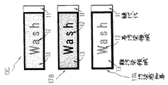
図1は汚染性感知素子と防汚性感知素子を付与した汚染感知器17を図示し、図1の中の17Aは汚染処理前のものを、17Bは汚染処理後のものを、17Cは汚染処理後に洗濯したものを示す。汚染感知器17の感知面には不織布が使用されており、ガラス転位温度(Tg)が−35℃のタック性(粘着性)透明アクリル樹脂エマルジョンを増粘した無着色汚染性感知素子組成物を「wash」とプリントし、その周囲の地部分にはガラス転移温度(Tg)が−5℃の非タック性透明アクリル樹脂エマルジョンと変性オルガノシリケート系撥水剤から成る無着色防汚性感知素子組成物がプリントされている。
【0013】
この汚染感知器17Aは、易汚染領域12(wash)と難汚染領域13(地部分)が、共に無着色透明の樹脂組成物の塗膜で設定されているので、汚染処理前に両者は見分けにくく、無着色汚染性感知素子組成物によって描かれた「wash」との文字を判読することは困難であるが、易汚染領域12には難汚染領域13に比して汚染物質が付着し易いので、汚染処理後には易汚染領域12が強く汚染され、その「wash」との文字が顕現して判読可能になる。そして、その後洗濯すると、汚染物質が除去され、汚染感知器17Bは汚染処理前の識別不能(17C)の状態に戻される。従って、図1の汚染感知器17が周縁に縫合されたカーテンでは、その易汚染領域12の文字「wash」が顕現したのを見てカーテンの汚染度を感知し、それを洗濯すればよく、汚れたカーテンを気付かずに使用し続けるようなことは回避される。尚、図1において、汚染処理前の汚染感知器17Aの無着色汚染性感知素子組成物によるプリント跡を「wash」と図示しているが、そのプリントインキが無着色のものであるから、実際にはプリント跡に「wash」と読み取れる文字は現れず、図1では、そのプリント跡を表示する説明の都合上で「wash」と図示されている。このことは、洗濯後の汚染感知器17Cの文字「wash」も同様である。
【0014】
図2は汚染性感知素子と防汚性感知素子の双方を部分的に付与した汚染感知器17を図示し、図1の中の17Aは汚染処理前のものを、17Bは汚染処理後のものを、17Cは汚染処理後に洗濯したものを示す。汚染感知器17は、弗素樹脂系防汚剤によって防汚処理された濃色防汚性感知素子糸条と、弗素樹脂系防汚剤によって防汚処理された淡茶色防汚性感知素子糸条と、ガラス転移温度(Tg)が−35℃のタック性透明アクリル樹脂エマルジョンに浸漬処理してアクリル樹脂が5重量%の付着した白色汚染性感知素子糸条によって織成され、その表面には、濃色防汚性感知素子糸条によって文字「Wash」が織り出され、その文字「Wash」に続く末尾には淡茶色防汚性感知素子糸条によって文字「ed」が織り出され、それらの文字を囲む地部分は白色汚染性感知素子糸条によって織成されている。
【0015】
この汚染感知器17Aでは、濃色防汚性感知素子糸条と淡茶色防汚性感知素子糸条によって織り出された難汚染領域13a・13bと、白色汚染性感知素子糸条によって織り出された易汚染領域12(地部分)が色分けされているので、汚染処理前に、その防汚性感知素子糸条によって織り出された文字「Washed」を判読することが出来る。しかし、汚染処理後は、汚染物質が付着し易い易汚染領域12(地部分)が変色しても、濃色防汚性感知素子糸条による難汚染領域13aほどには濃色にならず、その難汚染領域13aの文字「Wash」は判読可能な状態に残されるが、淡茶色防汚性感知素子糸条による難汚染領域13bと易汚染領域12との色差は薄れ、その難汚染領域13bの文字「ed」は判読不能になる。従って、図2の汚染感知器17が周縁に縫合されたカーテンでは、その淡茶色防汚性感知素子糸条による難汚染領域13bの文字「ed」が消え薄れ、濃色防汚性感知素子糸条による難汚染領域13aの文字「Wash」だけが残されているのを見てカーテンの汚染度を感知し、それを洗濯すればよく、汚れたカーテンを気付かずに使用し続けるようなことは回避される。
【0016】
このように、カーテンや垂れ幕のように洗濯機に投入して洗濯可能な内装品では、その周縁の一部に汚染感知器17を縫い付けておくとよい。図1と図2において、11は、汚染感知器の片端に設けられた縫付代である。ブラインド、襖、障子、家具類、天井張地、壁張地などのように洗濯機による洗濯が不可能な内装品では、その周縁の一部に汚染感知器17を貼付し、易汚染領域12と難汚染領域13の視覚上での変化によって汚染度を感知し、ブラインドでは取り外して洗浄し、襖や障子は取り外して張替え、家具類で拭き掃除をし、天井張地や壁張地では張替えたり塗装し直すことが出来る。
【0017】
汚染処理にフラッシュアイ、関東ローム土泥、カーボンブラック、タバコの煙を使用するのは、生活環境において浮遊する汚染物質の多くはその種の類のものであるからである。汚染表示の易汚染領域12と難汚染領域13との防汚性の差異を、円14で縁取られ、その円14の内部に易汚染領域12と難汚染領域13が設定されている試験試料15によって調べるのは、内装品の種類によって形の異なる汚染感知器17の形状、及び、易汚染領域12と難汚染領域13の形状(輪郭)を標準化するためである。試験試料15を、その円14の直径(Dcm)の100倍となる距離(100Dcm)から視力1の片眼で観察して調べるのは、内装品の種類によって大きさの異なる汚染感知器17の汚染表示(易汚染領域と難汚染領域形状)の大きさ(視野)、及び、観察する人(パネラー)を標準化するためである。そうすると、試験試料15の大きさの如何にかかわらず、内装品の直径1cmの円14で囲まれる部分の汚染の程度を、内装品から1m離れて観察した場合と同様に観察し判断することが出来る。
【0018】
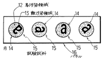
汚染感知器17が大き過ぎて内装品の美観を損なうようなことがないようにするため、又、内装品の汚染度は1m前後距離をおいて観察されることを考慮し、試験試料15として縁取る円14の大きさ(直径D)は10〜20mmにするとよい。易汚染領域12と難汚染領域13の配置(汚染表示)の識別検査には、試験試料15は数枚用意し、易汚染領域12と難汚染領域13の配置の方向を変えてパネル16に貼付し、視力(検眼)テストを行う場合と同じ要領で識別検査を行う(図3)。商品ラベルに兼用され、出所表示や品質表示、銘柄などの汚染表示とは無関係の表示を有する汚染感知器17、或いは、内装品(汚染感知器)の種類によって易汚染領域12と難汚染領域13を直径10〜20mmの一つの小さい円14に納めることが出来ない場合には、易汚染領域12と難汚染領域13をそれぞれ小さい円で囲んで切取り、その細かい円で縁取られた切り抜き(12・13)を一つの円14に納まるように台紙に貼り付けて試験試料15を調製する(図4)。
【0019】
汚染感知器17は、それに汚染表示(12・13)として日付や保証期間を表示し、汚染感知器17を内装品に取り付け、内装品の品質保証書や洗濯・清掃のサービスの品質保証書として使用することも出来る。
【0020】
汚染感知器17Aは、図5に図示するように、感知面の一部をカバー18によって露顕自在に、即ち、そのカバー18を随時外してその感知面の一部を露出し得るように、被覆して構成することも出来る。そのように構成された汚染感知器17では、感知面のカバー18によって露顕自在に被覆された部分が難汚染領域13となり、カバー18に被覆されずに露出している部分が易汚染領域12となり、難汚染領域13をカバー18から露出させて看取される易汚染領域12と難汚染領域13との色差によって汚染の程度を感知することになる。このようなカバー18は、補助的感知手段として、図1と図2に図示する汚染感知器17の易汚染領域12の一部に適用するとよい。カバー18には、防汚性と遮光性に富む布帛やプラスチックフイルムが使用される。図5において、19はカーテンを示し、分図(a)は汚染前の汚染感知器を示し、分図(b)は汚染後の汚染感知器を示す。
【0021】
【実施例】
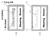
セミダル・ウーリー加工ポリエステル・マルチフィラメント糸(繊度220dtex/72F)を経糸と緯糸に使用して織成された経糸密度295本/10cm・緯糸密度307本/10cm・目付け260gf/m2 のポリエステル繊維平織物を、シリカ系防汚剤(アルキルシリケート)を用い、その固形分付着量を1%に設定してデップ・ニップ方式で防汚処理し、ガラス転位温度(Tg)−35℃のアクリル樹脂エマルジョンに増粘剤とアンモニア水を添加した無着色汚染性感知素子組成物をインキとして文字「Cleaning」(易汚染領域12)をプリントして汚染感知器17を作成した(図6)。
【0022】
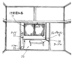
その汚染感知器17をドレープカーテン19の上縁から20cm下がった側縁に取り付け、3畳間20と6畳間21とから成り(図7と図8)、その3畳間20と6畳間21の間が常時開放されており、煙草(銘柄:セブンスター)を1日平均10本喫煙するパネラーが居住する居間の3畳間20の窓際に、そのドレープカーテン19を1年間吊るして使用した結果、その汚染感知器17にプリントされた易汚染領域12(文字;Cleaning)が看取され、ドレープカーテン19の汚れの度合いを確認することが出来た。図6において、分図(a)は汚染前の汚染感知器を示し、分図(b)は汚染後の汚染感知器を示す。図6において、汚染前の汚染感知器に無着色汚染性感知素子組成物によるプリント跡が「Cleaning」と図示されているが、そのプリント跡は、汚染前には看取されない。図7と図8において、22はテレビ、23はソファー、24はテーブルを示す。
【0023】
【発明の効果】
本発明によると、使用中の内装品の汚染度を汚染感知器17によって的確に感知し、その汚染度に応じて洗濯・清掃し、生活環境を清楚且つ衛生的に保つことが出来、内装品が汚れてもいないのに洗濯・清掃する無駄も省かれ、その維持管理費用を低減することが出来る。
【図面の簡単な説明】
【図1】本発明に係る汚染感知器の表面図である。
【図2】本発明に係る汚染感知器の表面図である。
【図3】本発明に係る試験試料の表面図である。
【図4】本発明に係る試験試料の表面図である。
【図5】本発明に係る汚染感知器の表面図である。
【図6】本発明に係る汚染感知器の表面図である。
【図7】本発明の実施に供された居間の見取図である。
【図8】本発明の実施に供された居間の透視図である。
【符号の説明】
11 縫付代
12 易汚染領域
13 難汚染領域
14 円
15 試験試料
16 パネル
17 汚染感知器
18 カバー
19 カーテン
20 3畳間
21 6畳間
22 テレビ
23 ソファー
24 テーブル[0001]
TECHNICAL FIELD OF THE INVENTION
The present invention relates to pollution detection for detecting the degree of contamination during use of interior goods (hereinafter simply referred to as interior goods) such as curtains, furniture, fittings, ceiling materials, wall materials, floor materials and the like that are used for a long time in a state of being left unattended. It is about a vessel.
[0002]
[Prior art]
Interior products are gradually contaminated by the attachment of fine contaminants floating in the living environment during use. However, contaminants floating in the living environment are extremely small and very fine. For this reason, the degree of contamination of interior components due to contaminants is not easily perceived, and it is actually the case that the degree of contamination is first noticed when compared with a new product.
[0003]
[Problems to be solved by the invention]
For this reason, regardless of the degree of contamination, cleaning dates are set for each season and are regularly washed, especially for commercial curtains used in hotels, office buildings, hospitals, etc. . However, it is wasteful to wash even if it is not so dirty, and conversely it is unsanitary if you do not notice that it is very dirty.
[0004]
[Object of the invention]
The present invention provides a pollution sensor that accurately detects the degree of contamination of an interior product in use, performs washing and cleaning according to the contamination level of an interior product in use, reduces the maintenance and management costs, and reduces the living environment. The purpose is to keep clean and hygienic.
[0005]
[Means for Solving the Problems]
The
[0006]
The second feature of the contamination sensor according to the present invention is that, in addition to the first feature, the difference in the contamination between the easily contaminated
[0007]
Dust contamination treatment: The
[0008]
Tobacco contamination treatment: The
[0009]
Another feature of the
[0010]
BEST MODE FOR CARRYING OUT THE INVENTION
The surface (hereinafter referred to as a sensing surface) of the
[0011]
As such, the sensing surface is provided with a contaminant sensing element having a property of promoting the attachment of a contaminant and / or an antifouling sensing element having a property of preventing the attachment of a contaminant. That is, when only the contaminant sensing element is provided, the provided portion becomes an easily contaminated region, and the portion not provided is a hardly contaminated region. When only the antifouling sensing element is provided, the provided portion becomes a hardly contaminated region, and the non-applied portion becomes an easily contaminated region. When both of them are partially applied, the portion provided with the contaminant sensing element becomes an easily contaminated region, and the portion provided with the antifouling sensing element becomes a hardly contaminated region. The pollution sensor partially provided with both the pollution sensing element and the antifouling sensing element is compared with the pollution sensor partially provided with either the pollution sensing element or the antifouling sensing element. However, the difference in the contamination between the easily contaminated area and the hardly contaminated area increases. The easily contaminated region and the hardly contaminated region may be classified according to the presence or absence of the antifouling sensing element and the contaminating sensing element. The antifouling sensing element uses an antifouling agent, an antistatic agent, a water repellent, and an oil repellent, and the fouling sensing element uses an adhesive, oil, moisture absorbent, surfactant, paste, and plasticizer. use. A preferred contamination sensing element is an acrylic resin having a glass transition temperature (Tg) of −25 ° C. or lower, preferably −35 ° C. or lower, more preferably around −65 ° C. (−60 ° C. to −70 ° C.).
[0012]
FIG. 1 shows a
[0013]
In the
[0014]
FIG. 2 shows a
[0015]
In the
[0016]
As described above, in the case of an interior product which can be washed by being put into a washing machine such as a curtain or a hanging curtain, the
[0017]
The use of flash eyes, Kanto loam mud, carbon black, and cigarette smoke for pollution treatment is because many of the pollutants floating in the living environment are of that type. The
[0018]
In order to prevent the
[0019]
The
[0020]
As shown in FIG. 5, the
[0021]
【Example】
A polyester fiber flat having a warp density of 295/10 cm, a weft density of 307/10 cm, and a basis weight of 260 gf / m 2 , woven using a semi-dal wooly-processed polyester multifilament yarn (fineness 220 dtex / 72F) for the warp and the weft. The woven fabric is subjected to an antifouling treatment using a silica-based antifouling agent (alkyl silicate), with the solid content attached thereto being set to 1%, by a dip-nip method, and an acrylic resin emulsion having a glass transition temperature (Tg) of −35 ° C. The character "Cleaning" (easily contaminated area 12) was printed using a non-colored contaminant sensing element composition obtained by adding a thickener and aqueous ammonia to the ink to prepare a contaminant detector 17 (FIG. 6).
[0022]
The
[0023]
【The invention's effect】
According to the present invention, the degree of contamination of the interior components in use can be accurately detected by the
[Brief description of the drawings]
FIG. 1 is a front view of a contamination detector according to the present invention.
FIG. 2 is a front view of a contamination detector according to the present invention.
FIG. 3 is a surface view of a test sample according to the present invention.
FIG. 4 is a surface view of a test sample according to the present invention.
FIG. 5 is a front view of a contamination detector according to the present invention.
FIG. 6 is a front view of a contamination detector according to the present invention.
FIG. 7 is a sketch of a living room provided for the implementation of the present invention.
FIG. 8 is a perspective view of a living room provided for carrying out the present invention.
[Explanation of symbols]
11
Claims (3)
記
(1) 塵埃汚染処理; 汚染感知器を厚み5mm以下・縦横各50mm以下の平板な試験片に調製し、易汚染領域と難汚染領域の設定されている表面の裏側に、非粘着面がプラスチックフイルムで構成された粘着シートを貼り合わせ、フライアッシュ0.2gと関東ローム土泥0.2gとカーボンブラック0.1gから成る合計0.5gfの汚れ粉末と共に、直径10cm・内部容積1リットルの円筒形容器に入れて蓋を閉め、その軸芯を水平に支持し、その円筒形容器を50rpmの回転速度で30分間回転し、その試験片を取り出して試験試料を調製する。
(2) タバコ汚染処理; 汚染感知器を厚み5mm以下・縦横各50mm以下の平板な試験片に調製し、易汚染領域と難汚染領域の設定されている表面の裏側に、非粘着面がプラスチックフイルムで構成された粘着シートを貼り合わせ、幅25cm・高さ40cm・奥行20cmのチャンバーの中央部に高さを5cmにして吊るし、10本の着火したタバコ(銘柄;ハイライト)をガラス繊維マットに載せてそのチャンバーの床面の中央部に設置し、チャンバーの蓋を閉めて24時間放置し、その試験片を取り出して試験試料を調製する。The difference in contamination between the easily contaminated area and the hardly contaminated area of the sensing display according to claim 1 is bordered by a circle, and the test sample in which the easily contaminated area and the hardly contaminated area are set inside the circle is used. Before and after any of the following contamination treatments, the surface on which the easily contaminated area and the hardly contaminated area are set is vertically supported, and has a diameter 100 times the diameter (Dcm) of the circle. When observing from a distance (100 Dcm) with one eye having an eyesight of 1, the arrangement of the easily contaminated area and the hardly contaminated area can be distinguished before or after the contamination treatment, and on one of the other sides. The contamination sensor according to claim 1, wherein the contamination sensor is in an indistinguishable degree.
(1) Dust Contamination Treatment; Prepare a contamination detector as a flat test piece of 5 mm or less in thickness and 50 mm or less in length and width, and a non-adhesive surface on the back side of the surface where the easily contaminated area and the hardly contaminated area are set. A pressure-sensitive adhesive sheet composed of a plastic film is stuck, and together with 0.2 g of fly ash, 0.2 g of Kanto loam mud and 0.1 g of carbon black, a total of 0.5 gf of dirt powder, a diameter of 10 cm and an internal volume of 1 liter. The lid is closed in a cylindrical container, its axis is horizontally supported, the cylindrical container is rotated at a rotation speed of 50 rpm for 30 minutes, and the test piece is taken out to prepare a test sample.
(2) Tobacco contamination treatment: A contamination detector is prepared as a flat test piece with a thickness of 5 mm or less and a length and width of 50 mm or less, and the non-adhesive surface is plastic on the back side of the surface where the easily contaminated area and the hardly contaminated area are set. A pressure-sensitive adhesive sheet composed of a film is stuck and suspended at the center of a chamber having a width of 25 cm, a height of 40 cm and a depth of 20 cm at a height of 5 cm. Ten ignited cigarettes (brand: highlight) are glass fiber mats. And placed in the center of the floor surface of the chamber, the lid of the chamber is closed and left for 24 hours, and the test piece is taken out to prepare a test sample.
Priority Applications (1)
| Application Number | Priority Date | Filing Date | Title |
|---|---|---|---|
| JP2002371548A JP2004206202A (en) | 2002-12-24 | 2002-12-24 | Pollution sensor |
Applications Claiming Priority (1)
| Application Number | Priority Date | Filing Date | Title |
|---|---|---|---|
| JP2002371548A JP2004206202A (en) | 2002-12-24 | 2002-12-24 | Pollution sensor |
Publications (1)
| Publication Number | Publication Date |
|---|---|
| JP2004206202A true JP2004206202A (en) | 2004-07-22 |
Family
ID=32810401
Family Applications (1)
| Application Number | Title | Priority Date | Filing Date |
|---|---|---|---|
| JP2002371548A Pending JP2004206202A (en) | 2002-12-24 | 2002-12-24 | Pollution sensor |
Country Status (1)
| Country | Link |
|---|---|
| JP (1) | JP2004206202A (en) |
Cited By (2)
| Publication number | Priority date | Publication date | Assignee | Title |
|---|---|---|---|---|
| WO2012134117A2 (en) * | 2011-03-25 | 2012-10-04 | 주식회사 에바코 | Suction device, contamination-sensing member applied to the suction device, suction sensor, selection member, evaporation member, outer case for the suction device, unit for supplying electricity to the suction device, eyelash-curling unit connected to the unit for supplying electricity to the suction device, and mobile phone connection unit connected to the unit for supplying electricity to the suction device |
| KR101463658B1 (en) | 2012-11-28 | 2014-11-20 | (주)엘지하우시스 | Carpet tile having pollution displaying structure |
Citations (8)
| Publication number | Priority date | Publication date | Assignee | Title |
|---|---|---|---|---|
| JPS6044016A (en) * | 1983-08-20 | 1985-03-08 | Matsushita Electric Works Ltd | Air purifier |
| JPS62268937A (en) * | 1986-05-16 | 1987-11-21 | Matsushita Seiko Co Ltd | Ventilation filter |
| JPS63100954A (en) * | 1986-10-17 | 1988-05-06 | Mitsubishi Electric Corp | Electrostatic precipitator |
| JPH0329625A (en) * | 1989-06-27 | 1991-02-07 | Matsushita Electric Ind Co Ltd | Electric cleaner |
| JPH07270556A (en) * | 1994-03-30 | 1995-10-20 | Toppan Printing Co Ltd | Production of elapsed time indicator |
| WO1998012048A1 (en) * | 1996-09-20 | 1998-03-26 | Hitachi, Ltd. | Thin photocatalytic film and articles provided with the same |
| JPH11290253A (en) * | 1998-04-13 | 1999-10-26 | Kao Corp | Sheet for cleaning |
| JP2003240297A (en) * | 2002-02-18 | 2003-08-27 | Toyo Aluminium Foil Products Kk | Filter for replacement and manufacturing method |
-
2002
- 2002-12-24 JP JP2002371548A patent/JP2004206202A/en active Pending
Patent Citations (8)
| Publication number | Priority date | Publication date | Assignee | Title |
|---|---|---|---|---|
| JPS6044016A (en) * | 1983-08-20 | 1985-03-08 | Matsushita Electric Works Ltd | Air purifier |
| JPS62268937A (en) * | 1986-05-16 | 1987-11-21 | Matsushita Seiko Co Ltd | Ventilation filter |
| JPS63100954A (en) * | 1986-10-17 | 1988-05-06 | Mitsubishi Electric Corp | Electrostatic precipitator |
| JPH0329625A (en) * | 1989-06-27 | 1991-02-07 | Matsushita Electric Ind Co Ltd | Electric cleaner |
| JPH07270556A (en) * | 1994-03-30 | 1995-10-20 | Toppan Printing Co Ltd | Production of elapsed time indicator |
| WO1998012048A1 (en) * | 1996-09-20 | 1998-03-26 | Hitachi, Ltd. | Thin photocatalytic film and articles provided with the same |
| JPH11290253A (en) * | 1998-04-13 | 1999-10-26 | Kao Corp | Sheet for cleaning |
| JP2003240297A (en) * | 2002-02-18 | 2003-08-27 | Toyo Aluminium Foil Products Kk | Filter for replacement and manufacturing method |
Cited By (3)
| Publication number | Priority date | Publication date | Assignee | Title |
|---|---|---|---|---|
| WO2012134117A2 (en) * | 2011-03-25 | 2012-10-04 | 주식회사 에바코 | Suction device, contamination-sensing member applied to the suction device, suction sensor, selection member, evaporation member, outer case for the suction device, unit for supplying electricity to the suction device, eyelash-curling unit connected to the unit for supplying electricity to the suction device, and mobile phone connection unit connected to the unit for supplying electricity to the suction device |
| WO2012134117A3 (en) * | 2011-03-25 | 2013-03-21 | 주식회사 에바코 | Suction device, contamination-sensing member applied to the suction device, suction sensor, selection member, evaporation member, outer case for the suction device, unit for supplying electricity to the suction device, eyelash-curling unit connected to the unit for supplying electricity to the suction device, and mobile phone connection unit connected to the unit for supplying electricity to the suction device |
| KR101463658B1 (en) | 2012-11-28 | 2014-11-20 | (주)엘지하우시스 | Carpet tile having pollution displaying structure |
Similar Documents
| Publication | Publication Date | Title |
|---|---|---|
| EP2059805B1 (en) | Microbe-sensitive indicators and use of the same | |
| US20060110719A1 (en) | Educational tools and methods for demonstrating enhanced performance characteristics of a textile product to a person | |
| US5142727A (en) | Carpet scrubbing bonnet | |
| JP2004206202A (en) | Pollution sensor | |
| TW201815454A (en) | Air filter with passivated filter life indicator | |
| US20040241385A1 (en) | Thermochromatic curtain | |
| Abdel-Kareem et al. | Treatment, conservation and restoration of the Bedouin dyed textiles in the museum of Jordanian heritage | |
| Maity et al. | Chemical risk assessment in textile and fashion | |
| CN213721171U (en) | Novel antistatic fiber blanket | |
| Glover | Conservation and storage: textiles | |
| Shibayama et al. | Removal of flour paste residues from a painted banner with alpha‐amylase | |
| JPH01250480A (en) | Cloth for interior part | |
| JPS62268937A (en) | Ventilation filter | |
| Saharudin et al. | Physical Home Sanitation as a Risk Factor for Acute Respiratory Infection in Children under 5 at Labuan Regency, Central Sulawesi | |
| Cannistraro et al. | THERMO HYGROMETRIC MONITORING USING WIRELESS SENSORS: STUDY OF SEVENTEENTH-CENTURY CHURCH’S MICROCLIMATIC CONDITIONS AND ENCLOSED RELIQUARY | |
| Rendell | preventive conservation solutions for textile collections | |
| Samui et al. | Care, maintenance and disposability of medical and protective textile products | |
| US4128447A (en) | Method and article treating pictures | |
| Macken | A preliminary investigation into the effect of solvent vapour on ingrained textile soiling | |
| JP2010188039A (en) | Cleaning sheet | |
| BUDU | The deterioration and degradation of icons with revetments. Case studies | |
| Singer et al. | The conservation of a fourth century ad painted Egyptian mummy shroud | |
| Bayer | Deposits on exhibition glass discussed using the example of the pressure mount of the''Liber Linteus''in the Archaeological museum of Zagreb | |
| Eagle | The Ins and Outs of Textiles | |
| Moynihan | Care of textile and costume collections in small museums and historical societies |
Legal Events
| Date | Code | Title | Description |
|---|---|---|---|
| A621 | Written request for application examination |
Free format text: JAPANESE INTERMEDIATE CODE: A621 Effective date: 20051110 |
|
| A977 | Report on retrieval |
Free format text: JAPANESE INTERMEDIATE CODE: A971007 Effective date: 20080327 |
|
| A131 | Notification of reasons for refusal |
Free format text: JAPANESE INTERMEDIATE CODE: A131 Effective date: 20080422 |
|
| A02 | Decision of refusal |
Free format text: JAPANESE INTERMEDIATE CODE: A02 Effective date: 20080909 |