JP2004205129A - Combustion control method for boiler and its device - Google Patents
Combustion control method for boiler and its device Download PDFInfo
- Publication number
- JP2004205129A JP2004205129A JP2002375879A JP2002375879A JP2004205129A JP 2004205129 A JP2004205129 A JP 2004205129A JP 2002375879 A JP2002375879 A JP 2002375879A JP 2002375879 A JP2002375879 A JP 2002375879A JP 2004205129 A JP2004205129 A JP 2004205129A
- Authority
- JP
- Japan
- Prior art keywords
- burner
- combustion
- main burner
- blower
- boiler
- Prior art date
- Legal status (The legal status is an assumption and is not a legal conclusion. Google has not performed a legal analysis and makes no representation as to the accuracy of the status listed.)
- Granted
Links
Images
Landscapes
- Regulation And Control Of Combustion (AREA)
- Control Of Steam Boilers And Waste-Gas Boilers (AREA)
Abstract
Description
【0001】
【発明の属する技術分野】
この発明は、ボイラの燃焼制御方法およびその装置に関するものである。
【0002】
【従来の技術】
通常、ボイラの燃焼制御方法においては、前記ボイラの缶内の蒸気圧に基づいて、主バーナの燃焼および停止を制御している。すなわち、前記缶内の蒸気圧が設定値を越えると、前記主バーナを停止させ、前記設定値を下回ると燃焼させている。前記主バーナの燃焼を開始させる際には、前記ボイラ内を掃気するためのプレパージが行われている。また、前記ボイラによっては、前記主バーナを停止させる際にも、前記ボイラ内を掃気するためのポストパージが行われている。
【0003】
したがって、前記主バーナを一旦停止させた後、再度燃焼を開始するには、少なくともプレパージを行う必要があり、前記主バーナを停止させてから再度燃焼させるまでには、プレパージに要する時間またはプレパージとポストパージを合わせた時間が必要となる。そのため、蒸気使用機器が通常より多量の蒸気を消費する状態では、プレパージやポストパージを行うことによる時間遅れにより、負荷に追随できなくなると云う問題があった。また、プレパージやポストパージを行うことにより、前記ボイラ内の熱が排出されるため、熱損失が増加し、前記ボイラの効率が低下すると云う問題があった。
【0004】
そこで、前記ボイラの負荷に対する追従性(以下、「負荷追従性」と云う)や、前記ボイラの効率が低下すると云う問題を解消するため、つぎのような燃焼制御方法が提案されている。すなわち、負荷による前記主バーナの停止後、前記ボイラにおける最小燃焼量時の送風量よりも少ない送風量でポストパージを行いながら待機し、負荷要求があったときには、プレパージを省略して、前記主バーナの燃焼を開始させるようにした燃焼制御方法(たとえば、特許文献1参照。)である。しかし、この燃焼制御方法においては、ポストパージが所定時間以上継続されず、前記ボイラ内の掃気が終了していない場合には、プレパージを行ってから前記主バーナの燃焼を開始する必要がある。そのため、この燃焼制御方法においては、負荷要求に対する追従性(以下、「負荷追従性」と云う)の向上に支障があった。
【0005】
また、前記のような負荷追従性や効率低下の問題を解消するため、つぎのような燃焼制御方法も提案されている。すなわち、前記主バーナの停止後、前記ボイラの負荷に応じて、前記主バーナへの点火用の小容量のバーナ(以下、「点火用バーナ」と云う)を継続して作動させるようにした燃焼制御方法(たとえば、特許文献2参照。)である。しかし、この燃焼制御方法においては、前記主バーナの停止中も前記点火用バーナへ燃焼用空気を供給するため、前記主バーナの燃焼時の送風量で送風機を作動させておく必要がある。そのため、この燃焼制御方法においては、前記点火用バーナが必要とする以上の燃焼用空気が供給されることとなり、結果として前記ボイラ内の熱が排出されるため、熱損失が増加し、前記ボイラの効率が低下すると云う問題があった。
【0006】
【特許文献1】
特開平10−169904号公報
【特許文献2】
特開平5−231640号公報
【0007】
【発明が解決しようとする課題】
この発明が解決しようとする課題は、ボイラの負荷追従性を一層向上させるとともに、主バーナの停止中における熱損失を一層低減させ、さらに点火用バーナの燃焼の安定化を達成することである。
【0008】
【課題を解決するための手段】
この発明は、前記課題を解決するためになされたもので、請求項1に記載の発明は、主バーナ,この主バーナの点火用バーナおよび前記各バーナへ燃焼用空気を供給する送風機を備え、負荷に応じて前記主バーナの燃焼量を調整するボイラの燃焼制御方法において、前記主バーナの停止中、前記点火用バーナを作動させるとともに、前記送風機を前記主バーナの最小燃焼量時の送風量よりも少ない送風量で作動させることを特徴としている。
【0009】
請求項2に記載の発明は、主バーナ,この主バーナの点火用バーナ,前記各バーナへ燃焼用空気を供給する送風機,前記送風機から前記主バーナへの第一空気流路および前記送風機から前記点火用バーナへの第二空気流路を備え、負荷に応じて前記主バーナの燃焼量を調整するボイラの燃焼制御方法において、前記主バーナの停止中、前記点火用バーナを作動させるとともに、前記送風機を前記主バーナの最小燃焼量時の送風量より少ない送風量で作動させ、前記第一空気流路を絞ることを特徴としている。
【0010】
さらに、請求項3に記載の発明は、主バーナと、この主バーナの点火用バーナと、前記各バーナへ燃焼用空気を供給する送風機と、前記送風機から前記主バーナへ燃焼用空気を供給する第一空気流路と、前記送風機から前記点火用バーナへ燃焼用空気を供給する第二空気流路と、前記第一空気流路に設けられた絞り手段と、前記送風機の送風量調整手段と、前記主バーナの停止中、前記送風量調整手段によって前記送風機を前記主バーナの最小燃焼量時の送風量より少ない送風量で作動させるとともに、前記点火用バーナを作動させ、前記絞り手段を前記第一空気流路を絞るように作動させる制御手段とを備えたことを特徴としている。
【0011】
【発明の実施の形態】
つぎに、この発明の実施の形態について説明する。この発明は、主バーナ,この主バーナの点火用バーナおよび前記各バーナへ燃焼用空気を供給する送風機を備え、負荷に応じて前記主バーナの燃焼量を調整するボイラにおいて好適に実施することができる。また、この発明は、とくに前記送風機から前記主バーナへの第一空気流路および前記送風機から前記点火用バーナへの第二空気流路を備えたボイラにおいて好適に実施することができる。ここにおいて、前記ボイラには、蒸気ボイラ,温水ボイラ,排熱ボイラなどのボイラのほか、給湯器,吸収式冷凍機の再熱器などを含んでいる。また、この発明を適用するボイラにおいて、前記主バーナの最小燃焼量は、前記点火用バーナ燃焼量よりもより多いものとする。また、前記主バーナの燃焼量の調整は、最大燃焼量と最小燃焼量との間で連続的に行われる場合と、段階的に行われる場合とがある。前記主バーナの燃焼量の調整が段階的に行われる場合、前記主バーナは、燃焼と停止の二段階で燃焼量を調整する二位置式の燃焼制御や、高燃焼,低燃焼および停止の三段階で燃焼量を調整する三位置式の燃焼制御などの多位置式の燃焼制御が行われるようになっている。
【0012】
まず、この発明の燃焼制御方法の第一の実施形態は、前記主バーナの停止中、前記点火用バーナを作動させるとともに、前記送風機を前記主バーナの最小燃焼量時の送風量よりも少ない送風量で作動させる燃焼制御方法である。すなわち、前記ボイラの運転開始後、前記ボイラの負荷に応じて、前記主バーナを停止させたとき(すなわち、前記主バーナが待機状態となったとき)、前記点火用バーナを作動状態とするとともに、前記送風機の送風量を前記主バーナの最小燃焼量時の送風量よりも少ない送風量(以下、「待機時送風量」と云う)に調整し、この状態を維持する。
【0013】
ここにおいて、前記点火用バーナは、前記ボイラの運転開始時、前記主バーナを最初に燃焼させる際に点火し、以後、前記主バーナの燃焼中,停止中に拘わらず、作動させておくこともできる。また、前記主バーナの最小燃焼量時とは、前記主バーナの燃焼制御上、もっとも少ない燃焼量である。たとえば、前記主バーナが、三位置制御式の燃焼制御の場合、前記最小燃焼量は、前記低燃焼時の燃焼量である。
【0014】
この第一の実施形態によると、前記主バーナの停止中、前記点火用バーナを作動させることにより、前記各バーナが同時に停止した状態がなくなるため、プレパージやポストパージを行う必要がなくなる。そのため、前記主バーナを再度燃焼させる場合には、プレパージやポストパージを行うことなく、前記点火用バーナから即座に点火することができ、前記ボイラの負荷追従性を向上させることができる。
【0015】
また、この第一の実施形態によると、前記主バーナの停止中、前記送風機の送風量を前記待機時送風量で作動させることにより、前記ボイラから燃焼用空気とともに排出される前記ボイラ内の熱が少なくなるので、熱損失が減少し、前記ボイラの効率の低下を防止することができる。
【0016】
つぎに、この発明の燃焼制御方法の第二の実施形態について説明する。この第二の実施形態の燃焼制御方法は、前記第一の実施形態の燃焼制御方法において、前記点火用バーナの燃焼の安定性に障害が生じる場合に好適な燃焼制御である。この第二実施形態の燃焼制御方法は、前記主バーナの停止中、前記点火用バーナを作動させるとともに、前記送風機を前記待機時送風量で作動させ、前記第一空気流路を絞るようにした燃焼制御方法である。
【0017】
すなわち、この第二の実施形態においては、前記第一の実施形態における制御内容に加え、前記主バーナの停止中、前記第一空気流路を絞るようにしている。ここにおいて、前記第一空気流路を絞るとは、前記第一空気流路の流路断面積を減少させると云う意味であって、前記第一空気流路を閉鎖する場合も含んでいる。また、前記第一空気流路を絞るとき、前記第二空気流路は、絞らない。
【0018】
さて、この第二の実施形態においては、前記主バーナの停止中、前記第一空気流路を絞ることにより、前記送風機から前記第一空気流路への燃焼用空気の流入量を減少させ、その分、前記送風機から前記第二空気流路への燃焼用空気の流入量を増加させることができる。そのため、前記送風機からの送風量を前記待機時送風量に減少させても、前記点火用バーナの燃焼に必要な量の燃焼用空気を前記点火用バーナへ供給することができるので、前記点火用バーナを安定して燃焼させることができる。したがって、前記ボイラの負荷に応じて、前記主バーナを再度燃焼させるときには、前記点火用バーナによって前記主バーナを確実に点火することができるので、前記ボイラの負荷追従性を確実に向上させることができる。また、この第二の実施形態によれば、前記主バーナの停止中、前記第一空気流路への燃焼用空気の流入量は、前記待機時送風量より少なくなるので、熱損失をさらに減少させることができる。
【0019】
すなわち、この第二の実施形態においては、前記主バーナの停止中、前記点火用バーナを安定して燃焼させることにより、前記ボイラの負荷追従性を確実に向上させることができるとともに、前記ボイラの熱効率の低下を確実に抑制することができる。
【0020】
つぎに、この発明の燃焼制御装置について説明する。この発明の燃焼制御装置は、前記主バーナ,前記点火用バーナ,前記送風機,前記第一空気流路,前記第二空気流路,前記第一空気流路に設けられた絞り手段,前記送風機の送風量調整手段および制御手段を備えている。ここにおいて、前記絞り手段は、前記第一空気流路の流路断面積を減少させる手段であって、具体的には、ダンパなどの流路断面積を絞る公知の手段である。前記絞り手段は、実施に応じて前記第一空気流路を閉鎖するように構成することができる。また、前記送風量調整手段は、前記送風機の回転数を調整することによって、前記送風機からの送風量を調整する手段であって、具体的には、インバータ装置や電圧調整器などである。
【0021】
前記制御手段は、前記主バーナの停止中、前記送風機を前記待機時送風量で作動させるとともに、前記点火用バーナを作動させ、前記絞り手段によって前記第一空気流路を絞る機能を備えている。この機能は、前記制御手段にソフトウェアとして記憶させてある。
【0022】
前記燃焼制御装置においては、前記主バーナの停止中、前記点火用バーナを作動させることにより、前記各バーナが同時に停止した状態がなくなるため、プレパージやポストパージを行う必要がなくなる。そのため、前記主バーナを再度燃焼させる場合には、前記点火用バーナによって即座に前記主バーナへ点火することができ、前記ボイラの負荷追従性を向上させることができる。
【0023】
また、前記燃焼制御装置においては、前記主バーナの停止中、前記送風量調整手段によって前記送風機を前記待機時送風量で作動させることにより、熱損失が減少し、前記ボイラの効率の低下を抑制することができる。さらに、前記燃焼制御装置においては、前記主バーナの停止中、前記絞り手段によって、前記第一空気流路を絞ることにより、前記送風機から前記第一空気流路への燃焼用空気の流入量を減少させ、その分、前記送風機から前記第二空気流路への燃焼用空気の流入量を増加させることができる。そのため、前記送風機の送風量を前記待機時送風量に減少させても、前記点火用バーナに必要な量の燃焼用空気を前記点火用バーナへ供給することができるので、前記点火用バーナを安定して燃焼させることができる。したがって、前記ボイラの負荷に応じて、前記主バーナを再度燃焼させる場合、前記点火用バーナによって前記主バーナを確実に点火することができるので、前記ボイラの負荷追従性を確実に向上させることができる。また、前記主バーナの停止中、前記第一空気流路への燃焼用空気の流入量は、前記待機時送風量よりも少なくなるので、熱損失をさらに減少させることができる。
【0024】
以上のように、この発明の燃焼制御方法および装置によれば、前記ボイラの負荷追従性を一層向上させることができるとともに、前記主バーナの停止中における熱損失を一層低減させることができる。しかも、この発明の燃焼制御方法および装置によれば、前記点火用バーナの燃焼の安定化を達成することができるので、前記ボイラの負荷追従性を確実に向上させることができる。
【0025】
【実施例】
以下、この発明の具体的実施例を図面に基づいて詳細に説明する。図1は、この発明の燃焼制御装置の一実施例の概略構成図であり、また図2は、この発明の燃焼制御方法のタイミングチャートである。ここで、この実施例のボイラは、蒸気ボイラであって、主バーナの燃焼量を高燃焼,低燃焼および停止の三位置で制御する,いわゆる三位置制御式の燃焼制御を採用している。
【0026】
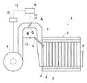
まず、図1を参照しながら、ボイラの基本構成について説明する。図1において、ボイラ1は、多数の伝熱管2,2,・・・を有する缶体3と、主バーナ4と、主バーナ4への点火用の小容量のバーナ(以下、「点火用バーナ」と云う)5と、前記各バーナ4,5へ燃焼用空気を供給するための送風機6とを備えている。
【0027】
前記缶体3内には、前記主バーナ4からの燃料ガスを燃焼させながら、前記各伝熱管2内の水との熱交換を行うためのガス通路7が形成されている。したがって、前記ガス通路7の一端部(図1の左側端部)には、前記主バーナ4が設けられており、また前記ガス通路7の他端部(図1の左側端部)は、排ガス出口8となっている。
【0028】
前記主バーナ4は、この実施例においては、平面状の燃焼面(予混合気の噴出面)を有する完全予混合式のバーナである。前記主バーナ4と前記送風機6との間には、前記送風機6からの燃焼用空気を前記主バーナ4へ供給するための第一空気流路9が設けられている。この第一空気流路9には、前記第一空気流路9の流路断面積を調整する絞り手段としてのダンパ10が設けられている。このダンパ10は、前記主バーナ4の燃焼時には、図1に点線で示す燃焼位置Aに制御され、前記主バーナ4の点火時には、図1に実線で示す点火位置Bに制御される。ここで、前記ダンパ10が前記点火位置Bにあるときは、前記燃焼位置Aに比べ、前記第一空気流路9の流路断面積が絞られることとなる。また、前記主バーナ4には、前記主バーナ4へ燃料ガスを供給するための第一燃料供給ライン(図示省略)が接続されている。
【0029】
前記点火用バーナ5は、前記主バーナ4の近傍に設けられている。この実施例では、前記主バーナ4の燃焼面の上端側に設けられている。前記点火用バーナ5と前記送風機6との間には、前記送風機6からの燃焼用空気を前記点火用バーナ5へ供給するための第二空気流路11が設けられている。また、前記点火用バーナ5には、前記点火用バーナ5へ燃料ガスを供給するための第二燃料供給ライン(図示省略)が接続されている。ここにおいて、前記点火用バーナ5の燃焼量は、前記主バーナ4の燃焼量の約1%〜5%である。
【0030】
前記送風機6には、送風量調整手段としてのインバータ装置12が接続されている。このインバータ装置12は、前記送風機6への供給電力の周波数を調整し、前記送風機6の回転数を調整することによって、送風量を調整することができるようになっている。
【0031】
そして、前記送風機6,前記ダンパ10および前記インバータ装置12は、回線13を介してそれぞれ制御器14に接続されている。この制御器14は、前記ボイラ1の負荷に基づいて、前記送風機6,前記ダンパ10および前記インバータ装置12を制御するとともに、前記各燃料供給ラインから前記各バーナ4,5へのガス燃料の供給を制御するように構成されている。これらの制御内容は、前記制御器14にソフトウェアとして記憶させてある。
【0032】
以上の構成において、前記制御器14による前記ボイラ1の概略動作は、以下の通りである。まず、前記ボイラ1を起動する際には、前記送風機6を起動させ、プレパージを行う。このプレパージは、前記送風機6を前記主バーナ4の高燃焼量に対応する送風量(以下、「高燃焼時送風量」と云う)で作動させ、前記ダンパ10を前記燃焼位置Aとした状態で行う。
【0033】
プレパージ終了後、前記主バーナ4への点火を行う際には、まず前記点火用バーナ5の点火を行う。前記点火用バーナ5の点火は、前記送風機6を前記高燃焼時送風量とし、前記ダンパ10を前記点火位置Bへ移動させた状態で、前記点火用バーナ5へ燃料ガスを供給し、点火手段(図示省略)を作動させることによって行う。つぎに、前記点火用バーナ5を点火させた後、前記主バーナ4へ燃料ガスを供給することにより、前記主バーナ4の点火を行う。
【0034】
そして、前記主バーナ4へ点火してから、所定時間経過後、前記送風機6を前記主バーナ4の低燃焼量に対応する送風量(以下、「低燃焼時送風量」と云う)で作動させるとともに、前記ダンパ10の位置を前記燃焼位置Aとする。そして、これ以後、前記ダンパ10を前記燃焼位置Aとした状態のまま、前記ボイラ1の負荷に応じて、前記送風機6の送風量および前記主バーナ4への燃焼量を調整することにより、前記主バーナ4を高燃焼,低燃焼および停止の三位置で制御する。ここで、前記主バーナ4は、前記ボイラ1の運転を停止させるまでは、停止した状態となっていても、前記ボイラ1の負荷に応じて、燃焼を再開するようになっている。すなわち、前記主バーナ4は、負荷要求に基づく燃焼再開のための待機状態となっている。
【0035】
そして、前記ボイラ1の運転を終了する際には、運転停止スイッチ(図示省略)の操作により、まず前記各バーナ4,5への燃料ガスの供給を停止し、前記ダンパ10を前記燃焼位置Aとした状態で、前記送風機6を前記高燃焼時送風量で所定時間運転し、ポストパージを行う。
【0036】
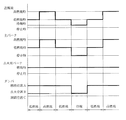
つぎに、この実施例の特徴部分について、図1および図2を参照しながら前記制御器14の制御内容とともに説明する。この特徴部分の制御内容も、前記制御器14にソフトウェアとして記憶させてある。この制御内容は、前記主バーナ4が待機状態のとき、前記送風機6を前記低燃焼時送風量より少ない送風量(以下、「待機時送風量」と云う)で作動させるとともに、前記点火用バーナ5を作動させ、前記ダンパ10によって前記第一空気流路9を絞ることである。以下、詳細に説明する。
【0037】
まず、この実施例において、前記点火用バーナ5は、図2に示すように、前記ボイラ1の運転を開始し、前記点火用バーナ5を点火した後は、前記主バーナ4の作動状態に拘わらず、前記ボイラ1の運転を終了させるときまで継続して作動させるようにしている。また、前記待機用送風量は、前記のように、前記低燃焼時送風量より少ない送風量である。
【0038】
このように、前記主バーナ4の待機中、前記点火用バーナ5を継続して作動させることにより、前記各バーナ4,5が同時に停止した状態がなくなるため、プレパージやポストパージを行う必要がなくなる。そのため、前記主バーナ4を再度燃焼させる場合には、前記点火用バーナ5によって前記主バーナ4を即座に点火することができ、前記ボイラ1の負荷追従性を向上させることができる。また、前記主バーナ4の待機中、前記送風機6を前記待機用送風量で作動させることにより、前記ボイラ1から燃焼用空気とともに排出される前記ボイラ1内の熱が少なくなるので、熱損失が減少し、前記ボイラ1の効率の低下を防止することができる。
【0039】
また、この実施例においては、前記主バーナ4の待機中、前記ダンパ10を前記点火位置Bとすることにより、前記第一空気流路9の流路断面積を絞るようにしている。このように、前記主バーナ4の待機中、前記第一空気流路9の流路断面積を絞ると、前記第一空気流路9側の圧損が増加するので、前記送風機6から前記第一空気流路9への燃焼用空気の流入量が減少し、この減少分、前記送風機6から前記第二空気流路11への燃焼用空気の流入量が増加する。そのため、前記送風機6の送風量を前記待機時送風量に減少させても、前記点火用バーナ5の燃焼に必要な量の燃焼用空気を前記点火用バーナ5へ供給することができるので、前記点火用バーナ5を安定して燃焼させることができる。
【0040】
したがって、この実施例においては、前記ボイラ1の負荷に応じて、前記主バーナ4を再度燃焼させる際、前記点火用バーナ5によって前記主バーナ4を確実に点火することができるので、前記ボイラ1の負荷追従性を確実に向上させることができる。また、この実施例において、前記主バーナ4の停止中、前記第一空気流路9への燃焼用空気の流入量は、前記待機時送風量よりも少なくなるので、熱損失をさらに減少させることができる。
【0041】
また、この実施例においては、前記主バーナ4の待機時、前記ダンパ10を前記点火位置Bとすることにより、前記第一空気流路9を絞っている。すなわち、前記ダンパ10の既存の構成を利用して、この発明を実施している。そのため、前記主バーナ4の待機時、前記第一空気流路9を絞るための装置を別個に設ける必要がない。
【0042】
ここにおいて、前記主バーナ4の待機時における前記送風機6からの送風量,すなわち前記待機時送風量は、つぎのように設定する。すなわち、前記待機時送風量は、前記ダンパ10によって前記第一空気流路9を絞ったとき、前記第二流路11へ流入する燃焼用空気の量が前記点火用バーナ5を安定して燃焼させることができる燃焼用空気の量と同等か、それよりも若干多くなるように設定する。
【0043】
ここにおいて、この実施例においては、前記主バーナ4の待機時、前記ダンパ10によって前記第一空気流路9を絞る際、前記ダンパ10を前記点火位置Bとしているが、この発明は、この実施例に限定されるものではない。すなわち、実施に応じて、図1および図2に示すように、前記第一空気流路9を閉鎖する閉鎖位置(図1に二点鎖線示)Cまで絞るように構成することができる。この場合、前記第一空気流路9が閉鎖されるので、前記送風機6からの燃焼用空気は全て前記第二空気流路11へ供給されることとなり、前記ボイラ1から燃焼用空気とともに排出される前記ボイラ1内の熱が一層少なくなるので、前記ボイラ1の効率の低下を一層抑えることができる。ここにおいて、前記送風機6からの送風量,すなわち待機時送風量は、前記点火用バーナ5を安定して燃焼させることができる燃焼用空気の量と同等か、それよりも若干多くなるように設定する。
【0044】
【発明の効果】
この発明によれば、ボイラの負荷追従性を一層向上させることができるとともに、バーナ停止中における熱損失を一層低減させることができる。しかも、この発明によれば、点火用バーナの燃焼の安定化を達成することができるので、負荷追従性を確実に向上させることができる。
【図面の簡単な説明】
【図1】この発明の燃焼制御装置の一実施例の概略構成図である。
【図2】この発明の燃焼制御方法のタイミングチャートである。
【符号の説明】
1 ボイラ
4 主バーナ
5 点火用バーナ
6 送風機
9 第一空気流路
10 ダンパ(絞り手段)
11 第二空気流路
12 インバータ装置(送風量調整手段)
14 制御装置(制御手段)[0001]
TECHNICAL FIELD OF THE INVENTION
The present invention relates to a boiler combustion control method and apparatus.
[0002]
[Prior art]
Usually, in the boiler combustion control method, the combustion and stop of the main burner are controlled based on the steam pressure in the boiler can. That is, when the vapor pressure in the can exceeds a set value, the main burner is stopped, and when the steam pressure falls below the set value, combustion is performed. When starting the combustion of the main burner, a pre-purge for purging the inside of the boiler is performed. Also, depending on the boiler, post-purge for purging the inside of the boiler is performed even when the main burner is stopped.
[0003]
Therefore, in order to restart the combustion after the main burner is once stopped, it is necessary to perform at least a pre-purge. The time required for post-purging is required. Therefore, in a state where the steam-consuming device consumes a larger amount of steam than usual, there is a problem that the load cannot follow the load due to a time delay caused by performing the pre-purge or the post-purge. In addition, since the heat in the boiler is discharged by performing the pre-purge and the post-purge, there is a problem that the heat loss increases and the efficiency of the boiler decreases.
[0004]
Therefore, the following combustion control method has been proposed in order to solve the problem that the boiler is capable of following the load (hereinafter referred to as “load following”) and the problem that the efficiency of the boiler is reduced. That is, after the main burner is stopped by the load, the boiler stands by while performing the post-purge with the blowing amount smaller than the blowing amount at the time of the minimum combustion amount. This is a combustion control method for starting combustion of a burner (for example, see Patent Document 1). However, in this combustion control method, if the post-purge is not continued for a predetermined time or more and the scavenging of the inside of the boiler is not completed, it is necessary to start the combustion of the main burner after performing the pre-purge. Therefore, in this combustion control method, there has been a problem in improving the ability to follow a load request (hereinafter, referred to as “load following ability”).
[0005]
In addition, the following combustion control method has been proposed to solve the problems of load following and efficiency reduction as described above. That is, after the main burner is stopped, a small-volume burner for ignition to the main burner (hereinafter, referred to as “ignition burner”) is continuously operated in accordance with the load on the boiler. This is a control method (for example, see Patent Document 2). However, in this combustion control method, since the combustion air is supplied to the ignition burner even when the main burner is stopped, it is necessary to operate the blower with the air volume at the time of combustion of the main burner. Therefore, in this combustion control method, more combustion air than is required by the ignition burner is supplied, and as a result, heat in the boiler is discharged, so that heat loss increases and the boiler However, there is a problem that the efficiency of the method is reduced.
[0006]
[Patent Document 1]
JP 10-169904 A [Patent Document 2]
JP-A-5-231640
[Problems to be solved by the invention]
The problem to be solved by the present invention is to further improve the load following capability of the boiler, further reduce the heat loss when the main burner is stopped, and achieve stable combustion of the ignition burner.
[0008]
[Means for Solving the Problems]
The present invention has been made to solve the above-mentioned problem, and the invention according to
[0009]
According to a second aspect of the present invention, there is provided a main burner, an ignition burner for the main burner, a blower for supplying combustion air to each of the burners, a first air flow path from the blower to the main burner and the blower from the blower. A combustion control method for a boiler comprising a second air flow path to an ignition burner and adjusting a combustion amount of the main burner according to a load, wherein the ignition burner is operated while the main burner is stopped. It is characterized in that the blower is operated with a blowing amount smaller than the blowing amount of the main burner at the time of the minimum burning amount, thereby narrowing the first air flow path.
[0010]
Furthermore, the invention according to
[0011]
BEST MODE FOR CARRYING OUT THE INVENTION
Next, an embodiment of the present invention will be described. The present invention can be suitably implemented in a boiler including a main burner, an ignition burner for the main burner, and a blower for supplying combustion air to each of the burners, and adjusting a combustion amount of the main burner according to a load. it can. Further, the present invention can be suitably implemented particularly in a boiler provided with a first air flow path from the blower to the main burner and a second air flow path from the blower to the ignition burner. Here, the boiler includes a boiler such as a steam boiler, a hot water boiler, and a waste heat boiler, as well as a water heater, a reheater of an absorption refrigerator, and the like. In the boiler to which the present invention is applied, the minimum combustion amount of the main burner is larger than the ignition burner combustion amount. Further, the adjustment of the combustion amount of the main burner may be performed continuously between the maximum combustion amount and the minimum combustion amount, or may be performed stepwise. When the adjustment of the combustion amount of the main burner is performed in a stepwise manner, the main burner is provided with a two-position type combustion control for adjusting the combustion amount in two stages of combustion and stop, and a three-stage control of high combustion, low combustion and stop. Multi-position combustion control such as three-position combustion control for adjusting the combustion amount in stages is performed.
[0012]
First, in the first embodiment of the combustion control method of the present invention, while the main burner is stopped, the ignition burner is operated, and the blower is supplied with a smaller amount of air than the minimum burn amount of the main burner. This is a combustion control method operated by the air flow. That is, after the operation of the boiler is started, when the main burner is stopped according to the load of the boiler (that is, when the main burner is in a standby state), the ignition burner is set to an operating state, and Then, the air flow rate of the blower is adjusted to an air flow rate smaller than the air flow rate of the main burner at the time of the minimum combustion amount (hereinafter, referred to as "standby air flow rate"), and this state is maintained.
[0013]
Here, the ignition burner may be ignited when the boiler is started to operate, when the main burner is first burned, and thereafter, may be operated regardless of whether the main burner is burning or stopped. it can. In addition, the term "minimum combustion amount of the main burner" means the minimum combustion amount in terms of combustion control of the main burner. For example, when the main burner is a three-position control type combustion control, the minimum combustion amount is the combustion amount at the time of the low combustion.
[0014]
According to the first embodiment, by operating the ignition burner while the main burner is stopped, the state in which the respective burners are not stopped at the same time is eliminated, so that it is not necessary to perform a pre-purge or a post-purge. Therefore, when the main burner is burned again, it is possible to immediately ignite from the ignition burner without performing pre-purge or post-purge, and it is possible to improve the load followability of the boiler.
[0015]
Further, according to the first embodiment, while the main burner is stopped, by operating the blower of the blower at the standby blower, heat in the boiler discharged together with combustion air from the boiler is discharged. , The heat loss is reduced, and a decrease in the efficiency of the boiler can be prevented.
[0016]
Next, a second embodiment of the combustion control method of the present invention will be described. The combustion control method according to the second embodiment is suitable for the combustion control method according to the first embodiment when the stability of combustion of the ignition burner is impaired. In the combustion control method according to the second embodiment, while the main burner is stopped, the ignition burner is operated, and the blower is operated at the standby flow rate to narrow the first air flow path. This is a combustion control method.
[0017]
That is, in the second embodiment, in addition to the control contents in the first embodiment, the first air flow path is restricted while the main burner is stopped. Here, narrowing the first air flow path means reducing the flow path cross-sectional area of the first air flow path, and includes closing the first air flow path. Further, when the first air flow path is restricted, the second air flow path is not restricted.
[0018]
Now, in the second embodiment, while the main burner is stopped, the first air flow path is throttled to reduce the amount of combustion air flowing into the first air flow path from the blower, Accordingly, the amount of combustion air flowing from the blower into the second air flow path can be increased. Therefore, even if the blowing amount from the blower is reduced to the standby blowing amount, combustion air of an amount necessary for combustion of the ignition burner can be supplied to the ignition burner. The burner can be stably burned. Therefore, when the main burner is burned again according to the load of the boiler, the main burner can be reliably ignited by the ignition burner, so that the load followability of the boiler can be reliably improved. it can. Further, according to the second embodiment, while the main burner is stopped, the amount of combustion air flowing into the first air flow path is smaller than the standby air flow rate, so that heat loss is further reduced. Can be done.
[0019]
That is, in the second embodiment, by stably burning the ignition burner while the main burner is stopped, the load followability of the boiler can be reliably improved, and the boiler A decrease in thermal efficiency can be reliably suppressed.
[0020]
Next, the combustion control device of the present invention will be described. The combustion control device according to the present invention is characterized in that the main burner, the ignition burner, the blower, the first air flow path, the second air flow path, throttle means provided in the first air flow path, It is provided with a blowing amount adjusting means and a control means. Here, the throttle means is a means for reducing the cross-sectional area of the first air flow path, and specifically, is a known means for reducing the cross-sectional area of the flow path such as a damper. The throttling means can be configured to close the first air flow path depending on the implementation. Further, the blower amount adjusting means is a means for adjusting the number of rotations of the blower to adjust the blower amount from the blower, and specifically includes an inverter device, a voltage regulator and the like.
[0021]
The control unit has a function of operating the blower at the standby air volume while the main burner is stopped, operating the ignition burner, and narrowing the first air flow path by the throttle unit. . This function is stored in the control means as software.
[0022]
In the combustion control device, by operating the ignition burner while the main burner is stopped, the state in which the burners are not stopped at the same time is eliminated, so that it is not necessary to perform a pre-purge or a post-purge. Therefore, when the main burner is burned again, the main burner can be immediately ignited by the ignition burner, and the load followability of the boiler can be improved.
[0023]
Further, in the combustion control device, while the main burner is stopped, the blower is operated at the standby blower by the blower blower, thereby reducing heat loss and suppressing a decrease in efficiency of the boiler. can do. Further, in the combustion control device, while the main burner is stopped, the throttle means narrows the first air flow path, thereby reducing an inflow amount of combustion air from the blower into the first air flow path. The amount of combustion air flowing from the blower into the second air passage can be increased accordingly. Therefore, even if the blowing amount of the blower is reduced to the standby blowing amount, a necessary amount of combustion air for the ignition burner can be supplied to the ignition burner, so that the ignition burner is stabilized. Can be burned. Therefore, when the main burner is burned again in accordance with the load of the boiler, the main burner can be reliably ignited by the ignition burner, so that the load followability of the boiler can be reliably improved. it can. Further, while the main burner is stopped, the amount of combustion air flowing into the first air flow path is smaller than the standby air flow rate, so that heat loss can be further reduced.
[0024]
As described above, according to the combustion control method and apparatus of the present invention, the load followability of the boiler can be further improved, and the heat loss during stoppage of the main burner can be further reduced. Moreover, according to the combustion control method and apparatus of the present invention, the combustion of the ignition burner can be stabilized, so that the load followability of the boiler can be reliably improved.
[0025]
【Example】
Hereinafter, specific embodiments of the present invention will be described in detail with reference to the drawings. FIG. 1 is a schematic configuration diagram of an embodiment of the combustion control device of the present invention, and FIG. 2 is a timing chart of the combustion control method of the present invention. Here, the boiler of this embodiment is a steam boiler, and employs a so-called three-position control type combustion control in which the combustion amount of a main burner is controlled at three positions of high combustion, low combustion, and stop.
[0026]
First, the basic configuration of a boiler will be described with reference to FIG. 1, a
[0027]
A
[0028]
In this embodiment, the main burner 4 is a completely premixed burner having a planar combustion surface (a surface for ejecting premixed gas). Between the main burner 4 and the
[0029]
The ignition burner 5 is provided near the main burner 4. In this embodiment, the main burner 4 is provided on the upper end side of the combustion surface. A second
[0030]
The
[0031]
The
[0032]
In the above configuration, the schematic operation of the
[0033]
When the main burner 4 is ignited after the end of the prepurge, first, the ignition burner 5 is ignited. The ignition of the ignition burner 5 is performed by supplying the fuel gas to the ignition burner 5 while the
[0034]
Then, after a predetermined time has elapsed since the main burner 4 was ignited, the
[0035]
When the operation of the
[0036]
Next, the characteristic portion of this embodiment will be described with reference to FIGS. 1 and 2 together with the control contents of the
[0037]
First, in this embodiment, as shown in FIG. 2, after starting the operation of the
[0038]
As described above, while the main burner 4 is on standby, the ignition burner 5 is continuously operated, so that the respective burners 4 and 5 are not stopped at the same time, so that it is not necessary to perform pre-purge or post-purge. . Therefore, when the main burner 4 is burned again, the main burner 4 can be ignited immediately by the ignition burner 5, and the load following ability of the
[0039]
Further, in this embodiment, while the main burner 4 is on standby, the
[0040]
Therefore, in this embodiment, when the main burner 4 is burned again in accordance with the load of the
[0041]
In this embodiment, when the main burner 4 is on standby, the
[0042]
Here, the amount of air blown from the
[0043]
Here, in this embodiment, when the main air burner 4 is on standby and the first
[0044]
【The invention's effect】
According to the present invention, the load following capability of the boiler can be further improved, and the heat loss during stoppage of the burner can be further reduced. Moreover, according to the present invention, the combustion of the ignition burner can be stabilized, so that the load following ability can be surely improved.
[Brief description of the drawings]
FIG. 1 is a schematic configuration diagram of one embodiment of a combustion control device of the present invention.
FIG. 2 is a timing chart of the combustion control method of the present invention.
[Explanation of symbols]
DESCRIPTION OF
11 Second
14 control device (control means)
Claims (3)
Priority Applications (1)
| Application Number | Priority Date | Filing Date | Title |
|---|---|---|---|
| JP2002375879A JP4554153B2 (en) | 2002-12-26 | 2002-12-26 | Boiler combustion control system |
Applications Claiming Priority (1)
| Application Number | Priority Date | Filing Date | Title |
|---|---|---|---|
| JP2002375879A JP4554153B2 (en) | 2002-12-26 | 2002-12-26 | Boiler combustion control system |
Publications (2)
| Publication Number | Publication Date |
|---|---|
| JP2004205129A true JP2004205129A (en) | 2004-07-22 |
| JP4554153B2 JP4554153B2 (en) | 2010-09-29 |
Family
ID=32813475
Family Applications (1)
| Application Number | Title | Priority Date | Filing Date |
|---|---|---|---|
| JP2002375879A Expired - Fee Related JP4554153B2 (en) | 2002-12-26 | 2002-12-26 | Boiler combustion control system |
Country Status (1)
| Country | Link |
|---|---|
| JP (1) | JP4554153B2 (en) |
Cited By (6)
| Publication number | Priority date | Publication date | Assignee | Title |
|---|---|---|---|---|
| WO2009087787A1 (en) * | 2008-01-08 | 2009-07-16 | Mitsubishi Heavy Industries, Ltd. | Burner structure |
| JP2012047382A (en) * | 2010-08-26 | 2012-03-08 | Miura Co Ltd | Boiler |
| JP2013044483A (en) * | 2011-08-25 | 2013-03-04 | Samson Co Ltd | Boiler performing pilot combustion |
| JP2015017750A (en) * | 2013-07-10 | 2015-01-29 | 株式会社サムソン | Combustion device which stops combustion before arrival of earthquake |
| JP2015190647A (en) * | 2014-03-27 | 2015-11-02 | 三浦工業株式会社 | boiler |
| JP2018126202A (en) * | 2017-02-06 | 2018-08-16 | 東京瓦斯株式会社 | Drying equipment |
-
2002
- 2002-12-26 JP JP2002375879A patent/JP4554153B2/en not_active Expired - Fee Related
Cited By (9)
| Publication number | Priority date | Publication date | Assignee | Title |
|---|---|---|---|---|
| WO2009087787A1 (en) * | 2008-01-08 | 2009-07-16 | Mitsubishi Heavy Industries, Ltd. | Burner structure |
| JP2009162441A (en) * | 2008-01-08 | 2009-07-23 | Mitsubishi Heavy Ind Ltd | Burner structure |
| CN101910726B (en) * | 2008-01-08 | 2013-08-07 | 三菱重工业株式会社 | Burner structure |
| US8561554B2 (en) | 2008-01-08 | 2013-10-22 | Mitsubishi Heavy Industries, Ltd. | Burner structure |
| JP2012047382A (en) * | 2010-08-26 | 2012-03-08 | Miura Co Ltd | Boiler |
| JP2013044483A (en) * | 2011-08-25 | 2013-03-04 | Samson Co Ltd | Boiler performing pilot combustion |
| JP2015017750A (en) * | 2013-07-10 | 2015-01-29 | 株式会社サムソン | Combustion device which stops combustion before arrival of earthquake |
| JP2015190647A (en) * | 2014-03-27 | 2015-11-02 | 三浦工業株式会社 | boiler |
| JP2018126202A (en) * | 2017-02-06 | 2018-08-16 | 東京瓦斯株式会社 | Drying equipment |
Also Published As
| Publication number | Publication date |
|---|---|
| JP4554153B2 (en) | 2010-09-29 |
Similar Documents
| Publication | Publication Date | Title |
|---|---|---|
| JP4554153B2 (en) | Boiler combustion control system | |
| US20220026066A1 (en) | Combustion apparatus | |
| JPH11211228A (en) | Combined water heater | |
| JP2005147558A (en) | Boiler performing low combustion by small-capacity burner | |
| JP4859512B2 (en) | Combustion boiler control method | |
| JP4176686B2 (en) | Combustion device with pilot burner | |
| JP4191359B2 (en) | Boiler with continuous combustion | |
| JP3561309B2 (en) | Boiler combustion control method | |
| JPH10122555A (en) | Air capacity control method by inverter device of boiler | |
| JP3022250B2 (en) | Blow control method for three-position combustion control boiler | |
| JP4166190B2 (en) | Cogeneration system | |
| JP4318540B2 (en) | Boilers that change combustion transition timing | |
| JPH08145339A (en) | Secondary air flow rate control method and apparatus for combustion of coal-fired boiler | |
| JPH10103668A (en) | Combustion equipment | |
| JPH08261445A (en) | Igniting and burning method of gas burner | |
| JP4791284B2 (en) | Combustion device | |
| JPS6237607A (en) | Starting procedure of burning device | |
| JPH09243058A (en) | Combustion control apparatus for boiler | |
| JP2024044230A (en) | Combustion device and method for operating the combustion device | |
| JP2004353978A (en) | Operation control device of boiler | |
| JPH08303759A (en) | Air volume controlling method during ignition | |
| JPH0311225A (en) | Combustion device | |
| JP2008002787A (en) | Combustion apparatus | |
| JP2000111008A (en) | Circulation controller for combustion exhaust gas | |
| KR20020009902A (en) | Control method for driving of heater |
Legal Events
| Date | Code | Title | Description |
|---|---|---|---|
| A621 | Written request for application examination |
Free format text: JAPANESE INTERMEDIATE CODE: A621 Effective date: 20050711 |
|
| A977 | Report on retrieval |
Free format text: JAPANESE INTERMEDIATE CODE: A971007 Effective date: 20070130 |
|
| A131 | Notification of reasons for refusal |
Free format text: JAPANESE INTERMEDIATE CODE: A131 Effective date: 20070911 |
|
| A521 | Request for written amendment filed |
Free format text: JAPANESE INTERMEDIATE CODE: A523 Effective date: 20071112 |
|
| A02 | Decision of refusal |
Free format text: JAPANESE INTERMEDIATE CODE: A02 Effective date: 20080603 |
|
| A521 | Request for written amendment filed |
Free format text: JAPANESE INTERMEDIATE CODE: A523 Effective date: 20080703 |
|
| A521 | Request for written amendment filed |
Free format text: JAPANESE INTERMEDIATE CODE: A523 Effective date: 20080707 |
|
| A911 | Transfer to examiner for re-examination before appeal (zenchi) |
Free format text: JAPANESE INTERMEDIATE CODE: A911 Effective date: 20080813 |
|
| A912 | Re-examination (zenchi) completed and case transferred to appeal board |
Free format text: JAPANESE INTERMEDIATE CODE: A912 Effective date: 20081017 |
|
| A521 | Request for written amendment filed |
Free format text: JAPANESE INTERMEDIATE CODE: A821 Effective date: 20100409 |
|
| A01 | Written decision to grant a patent or to grant a registration (utility model) |
Free format text: JAPANESE INTERMEDIATE CODE: A01 |
|
| A61 | First payment of annual fees (during grant procedure) |
Free format text: JAPANESE INTERMEDIATE CODE: A61 Effective date: 20100714 |
|
| FPAY | Renewal fee payment (event date is renewal date of database) |
Free format text: PAYMENT UNTIL: 20130723 Year of fee payment: 3 |
|
| R150 | Certificate of patent or registration of utility model |
Ref document number: 4554153 Country of ref document: JP Free format text: JAPANESE INTERMEDIATE CODE: R150 Free format text: JAPANESE INTERMEDIATE CODE: R150 |
|
| FPAY | Renewal fee payment (event date is renewal date of database) |
Free format text: PAYMENT UNTIL: 20140723 Year of fee payment: 4 |
|
| R250 | Receipt of annual fees |
Free format text: JAPANESE INTERMEDIATE CODE: R250 |
|
| R250 | Receipt of annual fees |
Free format text: JAPANESE INTERMEDIATE CODE: R250 |
|
| R250 | Receipt of annual fees |
Free format text: JAPANESE INTERMEDIATE CODE: R250 |
|
| R250 | Receipt of annual fees |
Free format text: JAPANESE INTERMEDIATE CODE: R250 |
|
| R250 | Receipt of annual fees |
Free format text: JAPANESE INTERMEDIATE CODE: R250 |
|
| R250 | Receipt of annual fees |
Free format text: JAPANESE INTERMEDIATE CODE: R250 |
|
| R250 | Receipt of annual fees |
Free format text: JAPANESE INTERMEDIATE CODE: R250 |
|
| R250 | Receipt of annual fees |
Free format text: JAPANESE INTERMEDIATE CODE: R250 |
|
| R250 | Receipt of annual fees |
Free format text: JAPANESE INTERMEDIATE CODE: R250 |
|
| LAPS | Cancellation because of no payment of annual fees |