JP2004205011A - Transmission - Google Patents
Transmission Download PDFInfo
- Publication number
- JP2004205011A JP2004205011A JP2002377357A JP2002377357A JP2004205011A JP 2004205011 A JP2004205011 A JP 2004205011A JP 2002377357 A JP2002377357 A JP 2002377357A JP 2002377357 A JP2002377357 A JP 2002377357A JP 2004205011 A JP2004205011 A JP 2004205011A
- Authority
- JP
- Japan
- Prior art keywords
- speed change
- input means
- shift
- force input
- spring
- Prior art date
- Legal status (The legal status is an assumption and is not a legal conclusion. Google has not performed a legal analysis and makes no representation as to the accuracy of the status listed.)
- Pending
Links
Images


Abstract
Description
【0001】
【発明が属する技術分野】
本発明は、鞍乗型車両におけるライダーなどからの変速用の操作力の入力により、リターンスプリングの弾性力に対抗しながら変速レバーを回動可能とし、この変速レバーの回動で被変速部材が変速動作させられるようにした変速装置に関するものである。
【0002】
【従来の技術】
【0003】
【特許文献1】特開平2−231293号公報
【0004】
上記変速装置には、従来、上記特許文献1に示されたものがある。この公報のものによれば、変速装置は、軸心回りに回動自在となるよう変速ケースに支承される変速操作軸と、この変速操作軸の一端部から径方向外方に突出する変速操作力入力用の変速ペダルである操作力入力手段と、上記変速操作軸の他端部から径方向外方に突出する変速レバーと、この変速レバーの回動端部に取り付けられた連動具を介しこの変速レバーに連動連結され、上記操作力入力手段に入力される変速操作力に上記変速操作軸と変速レバーとを介し連動して変速動作させられる被変速部材と、上記軸心回りの初期回動位置に上記操作力入力手段を保持させるようこの操作力入力手段を付勢するリターンスプリングとを備えている。
【0005】
車両の走行中、上記したように操作力入力手段は上記リターンスプリングにより上記軸心回りの初期回動位置に保持されており、これにより、走行中の振動で上記操作力入力手段ががたつくことは防止されている。
【0006】
一方、上記リターンスプリングの付勢力に対抗しながら上記操作力入力手段への踏動操作である変速操作力の入力操作をし、変速操作軸を介し変速レバーを所定角度分、繰り返し回動させれば、この回動に連動して上記被変速部材が変速動作させられ、これにより、所望の変速比で車両が走行可能とされる。
【0007】
【発明が解決しようとする課題】
ところで、上記したように操作力入力手段への変速操作力の入力操作はリターンスプリングの付勢力に対抗しながらするものであるため、この対抗分、上記変速操作力の入力操作は重くなりがちである。そこで、上記操作力入力手段への変速操作力の入力操作が軽くできるようにするため、上記リターンスプリングの付勢力を低下させたり、上記変速操作力の入力操作を助長するためのバネを設けることが考えられる。しかし、単にこのようにすると、上記リターンスプリングによる上記操作力入力手段への付勢力が低下して、車両の走行中の振動で、上記付勢力に対抗して上記操作力入力手段ががたつくおそれを生じる。
【0008】
本発明は、上記のような事情に注目してなされたもので、車両の走行中の振動などにより、初期状態での変速装置の操作力入力手段ががたつくということを防止すると共に、上記操作力入力手段への変速操作力の入力操作が軽快にできるようにし、また、これが変速装置の大形化を防止しつつ、かつ、簡単な構成で達成されるようにすることを課題とする。
【0009】
【課題を解決するための手段】
上記課題を解決するための本発明の変速装置は、次の如くである。なお、この項において各用語に付記した符号は、本発明の技術的範囲を後述の「発明の実施の形態」の項の内容に限定解釈するものではない。
【0010】
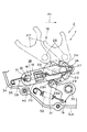
請求項1の発明は、図1〜4に例示するように、軸心11回りに回動自在となるよう変速ケース4に支承される変速操作軸12と、この変速操作軸12の一端部13から径方向外方に突出する変速操作力入力用の操作力入力手段14と、上記変速操作軸12の他端部15から径方向外方に突出する変速レバー16と、この変速レバー16の回動端部に取り付けられた連動具17を介しこの変速レバー16に連動連結され、上記操作力入力手段14に入力される変速操作力に上記変速操作軸12と変速レバー16とを介し連動して変速動作させられる被変速部材18と、上記軸心11回りの初期回動位置に上記操作力入力手段14を保持させるようこの操作力入力手段14を付勢するリターンスプリング20とを備え、上記変速操作軸12の軸方向で、上記変速レバー16を基準として上記変速操作軸12の一端部13と同じ側に上記被変速部材18を配置した変速装置において、
【0011】
一端部34が上記変速ケース4に連結され、他端部36が上記変速レバー16の回動端部側に連結されるアシストバネ38を設け、上記アシストバネ38のバネ中心39が上記変速操作軸12の軸心11を通るようにし、この変速操作軸12の軸心11に直交する面上で(図4)、上記変速操作力の入力により回動(図4、矢印A)する上記変速レバー16が、上記アシストバネ38のバネ中心39を上記変速レバー16の回動(A)方向とほぼ同じ方向に移動させるようにし、
【0012】
上記変速操作軸12の軸方向で、上記変速レバー16を基準として上記変速操作軸12の一端部13とは反対側に上記アシストバネ38を配置したものである。
【0013】
請求項2の発明は、図1〜4に例示するように、請求項1の発明に加えて、上記変速レバー16に対する上記アシストバネ38の他端部36の連結部を上記変速操作軸12の径方向で上記連動具17よりも外方に配置したものである。
【0014】
請求項3の発明は、図5〜9に例示するように、軸心11回りに回動自在となるよう変速ケース4に支承される変速操作軸12と、この変速操作軸12の一端部13から径方向外方に突出する変速操作力入力用の操作力入力手段14と、上記変速操作軸12の他端部15から径方向外方に突出する変速レバー16と、この変速レバー16に連動連結され、上記操作力入力手段14に入力される変速操作力に上記変速操作軸12と変速レバー16とを介し連動して変速動作させられる被変速部材18と、上記軸心11回りの初期回動位置に上記操作力入力手段14を保持させるようこの操作力入力手段14を付勢するリターンスプリング20とを備えた変速装置において、
【0015】
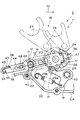
上記変速レバー16に連動連結される連動手段43を設け、一端部34が上記連動手段43に連結され、他端部36が上記変速レバー16の回動端部側に連結されるアシストバネ38を設け、上記アシストバネ38のバネ中心39が上記変速操作軸12の軸心11を通るようにし、この変速操作軸12の軸心11に直交する面上で(図7,9)、上記変速操作力の入力により回動(図7,9、矢印A)する上記変速レバー16と、この変速レバー16に連動する上記連動手段43とが、それぞれ上記アシストバネ38のバネ中心39を上記変速レバー16の回動(A)方向とほぼ同じ方向に移動させるようにしたものである。
【0016】
請求項4の発明は、図10に例示するように、軸心11回りに回動自在となるよう変速ケース4に支承される変速操作軸12と、この変速操作軸12の一端部13から径方向外方に突出する変速操作力入力用の操作力入力手段14と、上記変速操作軸12の他端部15から径方向外方に突出する変速レバー16と、この変速レバー16に連動連結され、上記操作力入力手段14に入力される変速操作力に上記変速操作軸12と変速レバー16とを介し連動して変速動作させられる被変速部材18と、上記軸心11回りの初期回動位置に上記操作力入力手段14を保持させるようこの操作力入力手段14を付勢するリターンスプリング20とを備えた変速装置において、
【0017】
上記変速レバー16に連動連結される連動手段43を設け、一端部34が上記変速ケース4に連結され、他端部36が上記連動手段43に連結されるアシストバネ38を設け、上記アシストバネ38のバネ中心39が上記変速操作軸12の軸心11を通るようにし、この変速操作軸12の軸心11に直交する面上で、上記変速操作力の入力により回動(図10、矢印A)する変速レバー16に連動(図10、矢印A)する上記連動手段43が、上記アシストバネ38のバネ中心39を上記変速レバー16の回動(A)方向とほぼ同じ方向に移動させるようにしたものである。
【0018】
請求項5の発明は、図10に例示するように、請求項4の発明に加えて、上記被変速部材18を上記変速動作させられた状態のままにバネ32により弾性的に保持可能とする保持手段19を備えた変速装置において、
【0019】
上記バネ32により上記アシストバネ38を構成したものである。
【0020】
請求項6の発明は、全図(特に、図11)に例示するように、軸心11回りに回動自在となるよう変速ケース4に支承される変速操作軸12と、この変速操作軸12から径方向外方に突出する変速操作力入力用の操作力入力手段14と、上記変速操作軸12に連動連結され、上記操作力入力手段14に入力される変速操作力に上記変速操作軸12を介し連動して変速動作させられる被変速部材18と、上記軸心11回りの初期回動位置に上記操作力入力手段14を保持させるようこの操作力入力手段14を付勢するリターンスプリング20とを備えた変速装置において、
【0021】
上記操作力入力手段14に変速操作力を入力してこの操作力入力手段14をその初期回動位置から上記軸心11回りで回動(各図、矢印A)させるとき、上記リターンスプリング20の付勢力に対抗して上記操作力入力手段14を上記回動(A)方向に付勢するアシストバネ38を設けたものである。
【0022】
請求項7の発明は、図11に例示するように、請求項6の発明に加えて、上記リターンスプリング20の付勢力に基づく上記軸心11回りのリターンモーメント(正)により上記操作力入力手段14が上記初期回動位置に保持されるようにし、上記アシストバネ38の付勢力に基づく上記軸心11回りのアシストモーメント(負)が上記リターンモーメントに対抗するようにし、上記操作力入力手段14の回動(A)が上記初期回動位置から進行するに伴い、上記アシストモーメントがほぼ0の値から漸次増大するようにしたものである。
【0023】
【発明の実施の形態】
以下、本発明の実施の形態を図面により説明する。
【0024】
(第1の実施の形態)
【0025】
図1〜4は、第1の実施の形態を示している。
【0026】
図において、符号1は自動二輪車等の鞍乗型車両であって、矢印Frはこの車両1の進行方向の前方を示している。
【0027】
上記車両1は車体と、この車体に支持され駆動源である内燃機関からの駆動力を変速して走行用駆動輪に伝達する変速装置2とを備えている。この変速装置2は、上記車体に支持される車体静止側部材3である変速ケース4と、この変速ケース4内に収容されこの変速ケース4に回転自在に支承される変速軸5と、この変速軸5に支持される変速歯車組6と、ライダーからの変速操作力を入力し上記変速歯車組6の噛合状態を変化させて所望の変速比にさせる変速操作装置7とを備えている。
【0028】
上記変速操作装置7は、車体の幅方向に延びる軸心11回りに回動自在となるようその軸方向の中途部が上記変速ケース4に支承される変速操作軸12と、この変速操作軸12の一方の自由端部である一端部13から径方向外方(後方)に突出してこの変速操作軸12と共に上記軸心11回りに所定角度範囲で往復回動自在とされる変速操作力入力用の変速ペダルである操作力入力手段14と、上記変速操作軸12の他方の自由端部である他端部15から径方向外方(図2〜4で示すように前方)に突出する変速レバー16と、この変速レバー16の回動端部に取り付けられた連動具17を介しこの変速レバー16に連動連結される一方、上記変速歯車組6と係合して、上記操作力入力手段14に入力されるライダーからの変速操作力に上記変速操作軸12と変速レバー16とを介し連動して上記変速歯車組6が所望の変速状態になるよう変速動作させられる被変速部材18と、この被変速部材18を上記変速動作させられた状態に弾性的に保持可能とする保持手段19と、上記軸心11回りのそれぞれ初期回動位置(図1〜3)に上記変速操作軸12、操作力入力手段14、および変速レバー16を弾性的に保持させるようこれら12,14,16を弾性的に付勢するリターンスプリング20とを備えている。なお、上記操作力入力手段14は手動操作用のレバーであってもよい。
【0029】
上記連動具17は、上記変速レバー16の回動端部に揺動自在に枢支される一対の係合爪22を備えている。
【0030】
上記被変速部材18は、上記軸心11と平行な他の軸心23回りに回動自在となるよう上記変速ケース4に支承されるカム筒体24と、このカム筒体24に平行に並設されて上記変速ケース4に支持される支軸25と、この支軸25に軸方向に摺動自在に支承され上記カム筒体24のカム溝26にカム係合する一方、上記変速歯車組6に係合する複数のシフトフォーク27と、上記カム筒体24の軸方向の端部に固着され上記係合爪22と係合可能な複数の係合ピン29aおよび複数のカム凹部29bを備える被係合体29とを備えている。
【0031】
上記保持手段19は、上記変速ケース4に枢支軸30により揺動自在に枢支されその揺動端部が上記カム凹部29bのいずれかに選択的にカム係合するカム係合体31と、このカム係合体31を上記カム凹部29bにカム係合させるよう弾性的に付勢するコイルスプリングであるバネ32とを備えている。
【0032】
一端部34が上記変速ケース4に掛止具35により連結され、他端部36が上記変速レバー16の回動端部側に掛止具37により連結されてその長手方向に引張力を有するコイルスプリングであるアシストバネ38が設けられている。上記変速操作軸12の軸方向に沿った視線でみて(図2〜4)、上記アシストバネ38のバネ中心39の長手方向の中途部40が上記変速操作軸12の軸心11を通ることとされている。また、上記変速レバー16に対する上記アシストバネ38の他端部36の連結部(掛止具37)が上記変速操作軸12の径方向で上記連動具17よりも外方に配置されている。
【0033】
上記変速操作軸12の軸方向で、上記変速レバー16を基準として上記変速操作軸12の一端部13と同じ側に上記被変速部材18が配置されている。また、上記変速操作軸12の軸方向で、上記変速レバー16を基準として上記変速操作軸12の一端部13とは反対側に上記アシストバネ38が配置され、このアシストバネ38は上記変速レバー16に沿ってほぼ平行に延びるよう配置され、かつ、この変速レバー16の近傍に並設されている。
【0034】
上記車両1を所望の変速比で走行させようとする場合には、上記リターンスプリング20の弾性力に対抗しながら上記操作力入力手段14の回動端部を変速操作力の入力操作する。すると、この操作力入力手段14はその初期回動位置(図1〜3)から、所定角度だけ上方に向って回動させられ、この回動に連動して上記変速操作軸12、変速レバー16、および連動具17の係合爪22が回動させられる(図4、矢印A)。
【0035】
すると、上記係合爪22に係合させられた上記被変速部材18の被係合体29の係合ピン29aが上記他の軸心23回りで回動させられ、これに連動して上記被変速部材18のカム筒体24が所定角度だけ回動させられ、このカム筒体24にカム係合するシフトフォーク27が上記支軸25の軸方向に移動させられ、即ち、上記被変速部材18が変速動作させられる。そして、このように変速動作させられる上記被変速部材18のシフトフォーク27に係合する変速歯車組6は、その噛合状態が変化させられる。この結果、上記操作力入力手段14への変速操作力の入力操作に応じて変速装置2の変速状態が変化させられて、車両1が変速させられる。
【0036】
上記被変速部材18が変速動作させられたとき、上記保持手段19のカム係合体31はバネ32の付勢力により上記被変速部材18の被係合体29のカム凹部29bにカム係合してこの被係合体29の自由な回動を弾性的に阻止し、これに伴い、上記被変速部材18のカム筒体24の回動や、係合爪22の移動が阻止され、つまり、上記被変速部材18は変速動作させられた状態のままにバネ32により弾性的に保持させられ、これに伴い、上記変速装置2の変速状態もそのままに保持される。
【0037】
一方、上記操作力入力手段14への変速操作力の入力操作を解除すれば、上記リターンスプリング20の付勢により上記変速レバー16と変速操作軸12とを介し上記操作力入力手段14が初期回動位置に戻され、上記操作力入力手段14への次の変速操作力の入力操作が可能とされる。
【0038】
そして、上記した操作力入力手段14への変速操作力の入力操作を繰り返し行えば、上記変速操作軸12、変速レバー16、および連動具17を介し被変速部材18のカム筒体24が、上記他の軸心23回りの一方向に向い所定角度ずつ間欠的に回動するよう変速動作させられて、その変速動作に応じて変速装置2に所望の変速状態が得られ、もって、所望の変速比で車両1が走行させられる。
【0039】
上記構成において、一端部34が上記車体静止側部材3である変速ケース4に連結され、他端部36が上記変速レバー16の回動端部側に連結されるアシストバネ38が設けられ、上記変速操作軸12の軸方向に沿った視線でみて、上記アシストバネ38のバネ中心39の長手方向の中途部40が上記変速操作軸12の軸心11を通ることとされている。
【0040】
このため、上記操作力入力手段14の初期回動位置(図1〜3)では、上記アシストバネ38は上記変速レバー16を回動させようとはしないことから、上記アシストバネ38を設けたとしても、上記操作力入力手段14は上記リターンスプリング20の付勢力によりその初期回動位置に保持される。
【0041】
一方、変速操作力が入力された上記操作力入力手段14に連動して上記変速レバー16がその初期回動位置から回動させられると(図4、矢印A)、上記変速操作軸12の軸心11に直交する面上で(図4)、上記アシストバネ38のバネ中心39は上記変速レバー16の回動(A)方向とほぼ同じ方向に移動させられるようになっている。
【0042】
このため、上記したように変速レバー16が回動(A)させられると、上記アシストバネ38の引張付勢力により上記変速レバー16をその回動(A)方向に更に回動させようとするモーメントが生じてこの変速レバー16の回動(A)が促進され、その分、上記操作力入力手段14への変速操作力を減少させることができて、この操作力入力手段14への変速操作力の入力操作が軽快にできることとなる。
【0043】
即ち、車両1の走行中で上記操作力入力手段14の不操作時である変速装置2の初期状態では、走行中の振動で上記操作力入力手段14が変速ケース4に対しがたつくということは、上記アシストバネ38に邪魔されることなく上記リターンスプリング20の付勢力により防止され、一方、上記操作力入力手段14への変速操作力の入力操作時には、上記アシストバネ38の付勢力により、上記リターンスプリング20に基づく上記軸心11回りのモーメント(リターンモーメント)が減少させられて、上記操作力入力手段14への変速操作力の入力操作が軽快にできることとなる。
【0044】
また、上記変速操作軸12の軸方向で、上記変速レバー16を基準として上記変速操作軸12の一端部13とは反対側に上記アシストバネ38を配置してある。
【0045】
このため、上記変速レバー16を基準として上記被変速部材18の反対側の空間が上記アシストバネ38の配置に有効利用されたことから、上記変速操作装置7の各構成部品16,18,38が互いにコンパクトに配置され、よって、上記アシストバネ38を設けても、上記変速操作装置7が大形になることは防止される。
【0046】
しかも、上記アシストバネ38を上記変速レバー16に沿ってほぼ平行に延びるよう配置し、かつ、この変速レバー16の近傍に配置してある。
【0047】
このため、上記変速操作装置7の各構成部品16,18,38はよりコンパクトに配置され、よって、上記アシストバネ38を設けても、上記変速操作装置7が大形になることは、より確実に防止される。
【0048】
また、前記したように、変速レバー16に対する上記アシストバネ38の他端部36の連結部を上記変速操作軸12の径方向で上記連動具17よりも外方に配置してある。
【0049】
このため、上記アシストバネ38の他端部36が上記変速操作軸12の軸心11からより遠くに離れることから、変速操作力が入力された上記操作力入力手段14に連動して上記変速レバー16がその初期回動位置から回動させられ(図4、矢印A)、上記変速操作軸12の軸心11に直交する面上で(図4)、上記アシストバネ38のバネ中心39が上記変速レバー16の回動(A)方向とほぼ同じ方向に移動させられるとき、上記変速レバー16の回動(A)を促進させるための上記アシストバネ38の引張付勢力によるモーメント(アシストモーメント)がより大きくなり、その分、上記操作力入力手段14への変速操作力の入力操作が、より軽快にできることとなる。
【0050】
以下の各図は、第2〜5の実施の形態を示している。これら各実施の形態は、前記第1の実施の形態と構成、作用効果において多くの点で共通している。そこで、これら共通するものについては、図面に共通の符号を付してその重複した説明を省略し、異なる点につき主に説明する。また、これら各実施の形態における各部分の構成を、本発明の課題、作用効果に照らして種々組み合せてもよい。
【0051】
(第2の実施の形態)
【0052】
図5〜7は、第2の実施の形態を示している。
【0053】
これによれば、上記変速レバー16に連動連結される連動手段43が設けられている。この連動手段43は、上記変速ケース4に枢支軸44により枢支される回動アーム45と、上記変速レバー16と回動アーム45のそれぞれの基部に形成され互いに噛合する歯車手段46とを備えている。また、一端部34が上記連動手段43の回動アーム45の回動端部側に掛止具35により連結され、他端部36が上記変速レバー16の回動端部側に掛止具37により連結されるアシストバネ38が設けられている。上記変速操作軸12の軸方向に沿った視線でみて、上記アシストバネ38のバネ中心39の長手方向の中途部40が上記変速操作軸12の軸心11を通っている(図6)。
【0054】
上記変速操作軸12の軸心11に直交する面上で(図7)、上記変速操作力の入力により回動する上記変速レバー16と、この変速レバー16に連動して回動する上記連動手段43とが、それぞれ上記アシストバネ38のバネ中心39を上記変速レバー16の回動方向とほぼ同じ方向に移動させるようになっている。
【0055】
上記構成によれば、変速レバー16に連動連結される連動手段43が設けられ、一端部34が上記連動手段43に連結され、他端部36が上記変速レバー16の回動端部側に連結されるアシストバネ38が設けられ、上記変速操作軸12の軸方向に沿った視線でみて、上記アシストバネ38のバネ中心39の長手方向の中途部40が上記変速操作軸12の軸心11を通ることとされている。
【0056】
このため、上記操作力入力手段14の初期回動位置(図5,6)では、上記アシストバネ38は上記変速レバー16を回動させようとはしないことから、上記アシストバネ38を設けたとしても、上記操作力入力手段14は上記リターンスプリング20の付勢力によりその初期回動位置に保持される。
【0057】
一方、変速操作力が入力された上記操作力入力手段14に連動して上記変速レバー16がその初期回動位置から回動させられる(図7、矢印A)と共に、この変速レバー16に連動して上記連動手段43の回動アーム45が回動させられると(図7、矢印A)、上記変速操作軸12の軸心11に直交する面上で(図7)、上記アシストバネ38のバネ中心39は、上記変速レバー16と連動手段43の回動アーム45とによりそれぞれほぼ同じ回動(A)方向に移動させられるようになっている。
【0058】
このため、上記変速レバー16の回動に加えて、この変速レバー16に連動手段43が連動させられると、上記軸心11に直交する面上で、上記アシストバネ38のバネ中心39は上記変速レバー16の回動(A)方向とほぼ同じ方向により大きく移動させられることから、上記アシストバネ38の引張付勢力により、上記変速レバー16をその回動方向に更に回動(A)させようとするモーメントがより大きくなってこの変速レバー16の回動(A)がより確実に促進され、その分、上記操作力入力手段14への変速操作力を減少させることができて、この操作力入力手段14への変速操作力の入力操作が極めて軽快にできることとなる。
【0059】
即ち、車両1の走行中で上記操作力入力手段14の不操作時には、走行中の振動で上記操作力入力手段14ががたつくということは、上記アシストバネ38に邪魔されることなく上記リターンスプリング20の付勢力により、より確実に防止され、一方、上記操作力入力手段14への変速操作力の入力操作時には、上記アシストバネ38の付勢力により、この変速操作力の入力操作が極めて軽快にできることとなる。
【0060】
(第3の実施の形態)
【0061】
図8,9は、第3の実施の形態を示している。
【0062】
この実施の形態は、前記第2の実施の形態とほぼ同じ構成であるが、上記変速レバー16の基部と回動アーム45の基部のうち、いずれか一方に設けられた係合ピン48と、他方に形成されてこの係合ピン48と係合する長孔形状の係合孔49とにより、上記変速レバー16に連動手段43が連動連結されている。
【0063】
上記構成による作用効果は、前記第2の実施の形態のものと同様であるが、これに加えて次の効果が生じる。
【0064】
即ち、上記変速レバー16に連動手段43を連動連結させるものは、互いに係合する係合ピン48と係合孔49とであってこれは単純な構成であることから、その分、上記変速操作装置7の構成を簡単にできる。
【0065】
(第4の実施の形態)
【0066】
図10は、第4の実施の形態を示している。
【0067】
これによれば、上記変速レバー16に連動連結される連動手段43が設けられている。この連動手段43は、上記変速ケース4に枢支軸44により枢支される回動アーム45と、上記変速レバー16と回動アーム45のそれぞれの基部に形成され互いに噛合する歯車手段46とを備えている。また、一端部34が上記連動手段43の回動アーム45の回動端部側に掛止具35により連結され、他端部36が上記車体静止側部材3である上記保持手段19のカム係合体31に連結されるアシストバネ38が設けられている。
【0068】
上記変速操作軸12の軸方向に沿った視線でみて、上記アシストバネ38のバネ中心39の長手方向の中途部40が上記変速操作軸12の軸心11を通っている(図10)。
【0069】
上記変速操作軸12の軸心11に直交する面上で、上記変速操作力の入力により回動(A)する上記変速レバー16と、この変速レバー16に連動して回動(A)する上記連動手段43の回動アーム45とが、それぞれ上記アシストバネ38のバネ中心39を上記変速レバー16の回動(A)方向とほぼ同じ方向に移動させるようになっている。
【0070】
上記構成による作用効果は、前記第1の実施の形態のものと同様であるが、これに加えて、次の効果が生じる。
【0071】
即ち、上記変速レバー16を回動(A)させたとき、この回動量にかかわらず、この変速レバー16に連動する連動手段43により、上記変速操作軸12の軸心11に直交する面上で、上記アシストバネ38のバネ中心39を上記変速レバー16の回動(A)方向とほぼ同じ方向により大きく移動させることができる。
【0072】
よって、上記アシストバネ38の引張付勢力により上記変速レバー16をその回動(A)方向に更に回動させようとするモーメントが生じてこの変速レバー16の回動(A)が、より確実に促進され、その分、上記操作力入力手段14への変速操作力を減少させることができて、この操作力入力手段14への変速操作力の入力操作がより軽快にできることとなる。
【0073】
また、上記保持手段19のバネ32により上記アシストバネ38を構成してある。
【0074】
このため、上記アシストバネ38を別途に設けることに比べて、変速操作装置7の構成部品の増加が防止され、よって、この変速操作装置7の構成を簡単にできる。
【0075】
(第5の実施の形態)
【0076】
図11は、第5の実施の形態を示しているが、その具体的構成は、前記各実施の形態のものによる。
【0077】
これによれば、上記操作力入力手段14に変速操作力を入力してこの操作力入力手段14をその初期回動位置から上記軸心11回りで回動(前記各図、矢印A)させるとき、上記リターンスプリング20の上記操作力入力手段14に対する付勢力は、上記操作力入力手段14を初期回動位置に戻して保持するよう働いて上記変速操作力に対抗し、上記操作力入力手段14の回動(A)に伴い、上記リターンスプリング20の付勢力の値が直線的(もしくは、多少曲線的)に増大する。
【0078】
一方、上記したように操作力入力手段14をその初期回動位置から上記軸心11回りで回動(A)させるとき、上記リターンスプリング20の付勢力に上記アシストバネ38の引張付勢力が対抗し、上記操作力入力手段14の回動(A)に伴い、上記アシストバネ38の付勢力の値が直線的(もしくは、多少曲線的)に減少しながら、上記アシストバネ38は上記操作力入力手段14を上記回動(A)方向に付勢する。
【0079】
このため、上記したように操作力入力手段14を回動(A)させると、上記リターンスプリング20の付勢力に対抗する上記アシストバネ38の付勢力により、上記操作力入力手段14の回動(A)が促進され、その分、上記操作力入力手段14への変速操作力を減少させることができて、この操作力入力手段14への変速操作力の入力操作が軽快にできることとなる。
【0080】
また、上記リターンスプリング20の付勢力に基づく上記軸心11回りのリターンモーメントにより上記操作力入力手段14が上記初期回動位置に保持されるようになっており、上記アシストバネ38の付勢力に基づく上記軸心11回りのアシストモーメントが上記リターンモーメントに対抗することとされている。そして、上記操作力入力手段14の回動(A)が上記初期回動位置から進行するに伴い、上記アシストモーメントがほぼ0の値から漸次増大することとされている。
【0081】
このため、上記操作力入力手段14を、その初期回動位置から回動(A)を進行させると、この進行に伴い上記リターンモーメントの値は増大するが、上記したように、操作力入力手段14の回動(A)の進行に伴い、上記リターンモーメントに対抗する上記アシストモーメントが漸次増大し、上記操作力入力手段14の回動(A)が進行しても、上記リターンモーメントとアシストモーメントとの合成結果が拡大することは小さく抑制され、つまり、操作力入力手段14に与えられるモーメントは小さく抑制される。よって、上記操作力入力手段14の各回動位置において、この操作力入力手段14への変速操作力の入力操作が軽快にできる。
【0082】
ここで、上記アシストバネ38を設けることなく、上記リターンスプリング20のばね定数を小さく(軟らかく)させ、これにより、操作力入力手段14への変速操作力の入力操作を軽快にさせるようにすることが考えられる。しかし、このようにした場合、操作力入力手段14をその初期回動位置から回動(A)を進行させると、上記リターンスプリング20の付勢力は、この操作力入力手段14の初期回動位置で初期設定した付勢力から単に増大するだけであり、つまり、そのリターンモーメントは単に増大するだけのため、上記アシストバネ38を設けた場合に比べ、上記操作力入力手段14の各回動位置における変速操作力の入力操作は重くなる。
【0083】
一方、上記操作力入力手段14の初期回動位置では、アシストバネ38によるアシストモーメントは生じないが、上記変速ケース4に対する操作力入力手段14の支承部に生じる摩擦力は、上記リターンスプリング20の付勢力に基づくだけではなく、上記摩擦力の一部は上記アシストバネ38が担うことから上記摩擦力が大きくなる。このため、この摩擦力により、上記操作力入力手段14の初期回動位置からの初期回動(A)が重くなるという作用が発生するが、上記リターンスプリング20のリターンモーメントに加え、上記リターンスプリング20とアシストバネ38との各付勢力に基づく摩擦力により、上記操作力入力手段14の初期回動位置で、この操作力入力手段14にがたつきの生じることが防止される。
【0084】
上記の場合、摩擦力の一部は上記アシストバネ38の付勢力が担っていて、上記摩擦力が大きくなりがちのため、上記リターンスプリング20の初期の付勢力を下げて、上記摩擦力を下げることができ、結局、上記した初期回動(A)が重くなるということは防止される。
【0085】
また、上記操作力入力手段14の可回動範囲におけるこの操作力入力手段14の各回動位置で、上記アシストモーメントは上記リターンモーメントよりも常に小さい値を保つこととされている。
【0086】
このため、上記操作力入力手段14をいずれの位置に回動させても、この操作力入力手段14はリターンスプリング20によって初期回動位置に戻されるよう付勢される。よって、上記操作力入力手段14を初期回動位置に戻すための操作も軽快にできる。
【0087】
【発明の効果】
本発明による効果は、次の如くである。
【0088】
請求項1の発明は、軸心回りに回動自在となるよう変速ケースに支承される変速操作軸と、この変速操作軸の一端部から径方向外方に突出する変速操作力入力用の操作力入力手段と、上記変速操作軸の他端部から径方向外方に突出する変速レバーと、この変速レバーの回動端部に取り付けられた連動具を介しこの変速レバーに連動連結され、上記操作力入力手段に入力される変速操作力に上記変速操作軸と変速レバーとを介し連動して変速動作させられる被変速部材と、上記軸心回りの初期回動位置に上記操作力入力手段を保持させるようこの操作力入力手段を付勢するリターンスプリングとを備え、上記変速操作軸の軸方向で、上記変速レバーを基準として上記変速操作軸の一端部と同じ側に上記被変速部材を配置した変速装置において、
【0089】
一端部が上記変速ケースに連結され、他端部が上記変速レバーの回動端部側に連結されるアシストバネを設け、上記アシストバネのバネ中心が上記変速操作軸の軸心を通るようにしてある。
【0090】
このため、上記操作力入力手段の初期回動位置では、上記アシストバネは上記変速レバーを回動させようとはしないことから、上記アシストバネを設けたとしても、上記操作力入力手段は上記リターンスプリングの付勢力によりその初期回動位置に保持される。
【0091】
また、上記変速操作軸の軸心に直交する面上で、上記変速操作力の入力により回動する上記変速レバーが、上記アシストバネのバネ中心を上記変速レバーの回動方向とほぼ同じ方向に移動させるようにしてある。
【0092】
このため、上記したように変速レバーが回動させられると、上記アシストバネの引張付勢力により上記変速レバーをその回動方向に更に回動させようとするモーメントが生じてこの変速レバーの回動が促進され、その分、上記操作力入力手段への変速操作力を減少させることができて、この操作力入力手段への変速操作力の入力操作が軽快にできることとなる。
【0093】
即ち、車両の走行中で、上記操作力入力手段の不操作時であるような変速装置の初期状態では、振動で上記操作力入力手段ががたつくということは、上記アシストバネに邪魔されることなく上記リターンスプリングの付勢力により防止され、一方、上記操作力入力手段への変速操作力の入力操作時には、上記アシストバネの付勢力により、この変速操作力の入力操作が軽快にできることとなる。
【0094】
また、上記変速操作軸の軸方向で、上記変速レバーを基準として上記変速操作軸の一端部とは反対側に上記アシストバネを配置してある。
【0095】
このため、上記変速レバーを基準として上記被変速部材の反対側の空間が上記アシストバネの配置に有効利用されたことから、上記変速装置の各構成部品が互いにコンパクトに配置され、よって、上記アシストバネを設けても、上記変速装置が大形になることは防止される。
【0096】
請求項2の発明は、上記変速レバーに対する上記アシストバネの他端部の連結部を上記変速操作軸の径方向で上記連動具よりも外方に配置してある。
【0097】
このため、上記アシストバネの他端部が上記変速操作軸の軸心からより遠くに離れることから、変速操作力が入力された上記操作力入力手段に連動して上記変速レバーがその初期回動位置から回動させられ、上記変速操作軸の軸心に直交する面上で、上記アシストバネのバネ中心が上記変速レバーの回動方向とほぼ同じ方向に移動させられるとき、上記変速レバーの回動を促進させるための上記アシストバネの引張付勢力によるモーメントがより大きくなり、その分、上記操作力入力手段への変速操作力の入力操作が、より軽快にできることとなる。
【0098】
請求項3の発明は、軸心回りに回動自在となるよう変速ケースに支承される変速操作軸と、この変速操作軸の一端部から径方向外方に突出する変速操作力入力用の操作力入力手段と、上記変速操作軸の他端部から径方向外方に突出する変速レバーと、この変速レバーに連動連結され、上記操作力入力手段に入力される変速操作力に上記変速操作軸と変速レバーとを介し連動して変速動作させられる被変速部材と、上記軸心回りの初期回動位置に上記操作力入力手段を保持させるようこの操作力入力手段を付勢するリターンスプリングとを備えた変速装置において、
【0099】
上記変速レバーに連動連結される連動手段を設け、一端部が上記連動手段に連結され、他端部が上記変速レバーの回動端部側に連結されるアシストバネを設け、上記アシストバネのバネ中心が上記変速操作軸の軸心を通るようにしてある。
【0100】
このため、上記操作力入力手段の初期回動位置では、上記アシストバネは上記変速レバーを回動させようとはしないことから、上記アシストバネを設けたとしても、上記操作力入力手段は上記リターンスプリングの付勢力によりその初期回動位置に保持される。
【0101】
また、上記変速操作軸の軸心に直交する面上で、上記変速操作力の入力により回動する上記変速レバーと、この変速レバーに連動する上記連動手段とが、それぞれ上記アシストバネのバネ中心を上記変速レバーの回動方向とほぼ同じ方向に移動させるようにしてある。
【0102】
このため、上記変速レバーの回動に加えて、この変速レバーに連動手段が連動させられると、上記軸心に直交する面上で、上記アシストバネのバネ中心は上記変速レバーの回動方向とほぼ同じ方向により大きく移動させられることから、上記アシストバネの付勢力により、上記変速レバーをその回動方向に更に回動させようとするモーメントがより大きくなってこの変速レバーの回動がより確実に促進され、その分、上記操作力入力手段への変速操作力を減少させることができて、この操作力入力手段への変速操作力の入力操作が極めて軽快にできることとなる。
【0103】
即ち、車両の走行中で、上記操作力入力手段の不操作時であるような変速装置の初期状態では、振動で上記操作力入力手段ががたつくということは、上記アシストバネに邪魔されることなく上記リターンスプリングの付勢力により、より確実に防止され、一方、上記操作力入力手段への変速操作力の入力操作時には、上記アシストバネの付勢力により、この変速操作力の入力操作が極めて軽快にできることとなる。
【0104】
請求項4の発明は、軸心回りに回動自在となるよう変速ケースに支承される変速操作軸と、この変速操作軸の一端部から径方向外方に突出する変速操作力入力用の操作力入力手段と、上記変速操作軸の他端部から径方向外方に突出する変速レバーと、この変速レバーに連動連結され、上記操作力入力手段に入力される変速操作力に上記変速操作軸と変速レバーとを介し連動して変速動作させられる被変速部材と、上記軸心回りの初期回動位置に上記操作力入力手段を保持させるようこの操作力入力手段を付勢するリターンスプリングとを備えた変速装置において、
【0105】
上記変速レバーに連動連結される連動手段を設け、一端部が上記変速ケースに連結され、他端部が上記連動手段に連結されるアシストバネを設け、上記アシストバネのバネ中心が上記変速操作軸の軸心を通るようにし、この変速操作軸の軸心に直交する面上で、上記変速操作力の入力により回動する変速レバーに連動する上記連動手段が、上記アシストバネのバネ中心を上記変速レバーの回動方向とほぼ同じ方向に移動させるようにしてある。
【0106】
本発明による作用効果は、前記請求項1に記載のものと同様であるが、これに加えて、次の効果が生じる。
【0107】
即ち、上記変速レバーを回動させたとき、この回動量にかかわらず、この変速レバーに連動する連動手段により、上記変速操作軸の軸心に直交する面上で、上記アシストバネのバネ中心を上記変速レバーの回動方向とほぼ同じ方向により大きく移動させることができる。
【0108】
よって、上記アシストバネの付勢力により上記変速レバーの回動が、より確実に促進され、その分、上記操作力入力手段への変速操作力の入力操作がより軽快にできることとなる。
【0109】
請求項5の発明は、上記被変速部材を上記変速動作させられた状態のままにバネにより弾性的に保持可能とする保持手段を備えた変速装置において、
【0110】
上記バネにより上記アシストバネを構成してある。
【0111】
このため、上記アシストバネを別途に設けることに比べて、変速操作装置の構成部品の増加が防止され、よって、この変速操作装置の構成を簡単にできる。
【0112】
請求項6の発明は、軸心回りに回動自在となるよう変速ケースに支承される変速操作軸と、この変速操作軸から径方向外方に突出する変速操作力入力用の操作力入力手段と、上記変速操作軸に連動連結され、上記操作力入力手段に入力される変速操作力に上記変速操作軸を介し連動して変速動作させられる被変速部材と、上記軸心回りの初期回動位置に上記操作力入力手段を保持させるようこの操作力入力手段を付勢するリターンスプリングとを備えた変速装置において、
【0113】
上記操作力入力手段に変速操作力を入力してこの操作力入力手段をその初期回動位置から上記軸心回りで回動させるとき、上記リターンスプリングの付勢力に対抗して上記操作力入力手段を上記回動方向に付勢するアシストバネを設けてある。
【0114】
このため、上記したように操作力入力手段を回動させると、上記リターンスプリングの付勢力に対抗する上記アシストバネの付勢力により、上記操作力入力手段の回動が促進され、その分、上記操作力入力手段への変速操作力を減少させることができて、この操作力入力手段への変速操作力の入力操作が軽快にできることとなる。
【0115】
請求項7の発明は、上記リターンスプリングの付勢力に基づく上記軸心回りのリターンモーメントにより上記操作力入力手段が上記初期回動位置に保持されるようにし、上記アシストバネの付勢力に基づく上記軸心回りのアシストモーメントが上記リターンモーメントに対抗するようにし、上記操作力入力手段の回動が上記初期回動位置から進行するに伴い、上記アシストモーメントがほぼ0の値から漸次増大するようにしてある。
【0116】
このため、上記操作力入力手段を、その初期回動位置から回動を進行させると、この進行に伴い上記リターンモーメントの値は増大するが、上記したように、操作力入力手段の回動の進行に伴い、上記リターンモーメントに対抗する上記アシストモーメントが漸次増大し、上記操作力入力手段の回動が進行しても、上記リターンモーメントとアシストモーメントとの合成結果が拡大することは小さく抑制される。よって、上記操作力入力手段の各回動位置において、この操作力入力手段への変速操作力の入力操作が軽快にできる。
【図面の簡単な説明】
【図1】第1の実施の形態で、変速装置の平面展開図である。
【図2】第1の実施の形態で、図1の2‐2線矢視図である。
【図3】第1の実施の形態で、図2の部分破断図である。
【図4】第1の実施の形態で、作用説明図であって図3に相当する図である。
【図5】第2の実施の形態で、図1に相当する図である。
【図6】第2の実施の形態で、図3に相当する図である。
【図7】第2の実施の形態で、図4に相当する図である。
【図8】第3の実施の形態で、図3に相当する図である。
【図9】第3の実施の形態で、図4に相当する図である。
【図10】第4の実施の形態で、図3に相当する図である。
【図11】第5の実施の形態で、操作力入力手段の回動角に対する付勢力とモーメントのグラフ図である。
【符号の説明】
1 車両
2 変速装置
3 車体静止側部材
4 変速ケース
7 変速操作装置
11 軸心
12 変速操作軸
13 一端部
14 操作力入力手段
15 他端部
16 変速レバー
17 連動具
18 被変速部材
19 保持手段
20 リターンスプリング
32 バネ
34 一端部
36 他端部
38 アシストバネ
39 バネ中心
40 中途部
43 連動手段[0001]
TECHNICAL FIELD OF THE INVENTION
The present invention enables a shift lever to rotate while opposing the elastic force of a return spring by inputting a shift operation force from a rider or the like in a straddle-type vehicle. The present invention relates to a speed change device capable of performing a speed change operation.
[0002]
[Prior art]
[0003]
[Patent Document 1] JP-A-2-231293
[0004]
Conventionally, as the above-mentioned transmission, there is one disclosed in
[0005]
During traveling of the vehicle, the operating force input means is held at the initial rotation position around the axis by the return spring as described above, so that the operating force input means does not rattle due to vibration during traveling. Has been prevented.
[0006]
On the other hand, a shift operation force, which is a stepping operation on the operation force input means, is input while opposing the urging force of the return spring, and the shift lever is repeatedly rotated by a predetermined angle via the shift operation shaft. For example, in response to the rotation, the speed-changed member is caused to perform a speed-change operation, whereby the vehicle can run at a desired speed ratio.
[0007]
[Problems to be solved by the invention]
By the way, as described above, the input operation of the shift operation force to the operation force input means is performed while opposing the urging force of the return spring. Therefore, the input operation of the shift operation force tends to be heavy by the amount of the opposition. is there. Therefore, in order to reduce the input operation of the shift operation force to the operation force input unit, a spring for reducing the urging force of the return spring or promoting the input operation of the shift operation force is provided. Can be considered. However, simply doing so reduces the urging force of the return spring on the operating force input means, and may cause the operating force input means to rattle against the urging force due to vibration during traveling of the vehicle. Occurs.
[0008]
SUMMARY OF THE INVENTION The present invention has been made in view of the circumstances described above, and prevents the operation force input means of the transmission in an initial state from rattling due to vibration or the like while the vehicle is running, and at the same time, the operation force An object of the present invention is to make it possible to lightly input a shift operation force to input means, and to achieve this with a simple configuration while preventing an increase in the size of the transmission.
[0009]
[Means for Solving the Problems]
A transmission according to the present invention for solving the above problems is as follows. Note that the reference numerals added to the terms in this section do not limit the technical scope of the present invention to the contents of the “Embodiments of the Invention” described below.
[0010]
As shown in FIGS. 1 to 4, the invention of
[0011]
One
[0012]
The
[0013]
According to a second aspect of the present invention, as shown in FIGS. 1 to 4, in addition to the first aspect of the present invention, a connecting portion of the
[0014]
As shown in FIGS. 5 to 9, the invention according to
[0015]
Provided is an interlocking means 43 interlockingly connected to the
[0016]
As shown in FIG. 10, the invention of claim 4 provides a speed
[0017]
Provided is an interlocking means 43 interlockingly connected to the
[0018]
According to a fifth aspect of the present invention, as shown in FIG. 10, in addition to the fourth aspect of the present invention, the
[0019]
The
[0020]
As shown in all the drawings (especially, FIG. 11), the invention according to claim 6 includes a speed
[0021]
When a shift operation force is input to the operation force input means 14 to rotate the operation force input means 14 around the
[0022]
According to a seventh aspect of the present invention, as shown in FIG. 11, in addition to the sixth aspect, the operating force input means is provided by a return moment (positive) about the
[0023]
BEST MODE FOR CARRYING OUT THE INVENTION
Hereinafter, embodiments of the present invention will be described with reference to the drawings.
[0024]
(First Embodiment)
[0025]
1 to 4 show a first embodiment.
[0026]
In the figure,
[0027]
The
[0028]
The speed
[0029]
The interlocking
[0030]
The
[0031]
A
[0032]
One
[0033]
In the axial direction of the speed
[0034]
When the
[0035]
Then, the
[0036]
When the speed-
[0037]
On the other hand, when the input operation of the shift operation force to the operation force input means 14 is released, the operation force input means 14 is initialized by the bias of the
[0038]
When the input operation of the shift operation force to the operation force input means 14 is repeatedly performed, the
[0039]
In the above configuration, there is provided an
[0040]
For this reason, at the initial rotation position of the operation force input means 14 (FIGS. 1 to 3), the
[0041]
On the other hand, when the
[0042]
Therefore, when the
[0043]
That is, in the initial state of the
[0044]
The
[0045]
For this reason, the space on the opposite side of the speed-changed
[0046]
Further, the
[0047]
For this reason, the
[0048]
Further, as described above, the connecting portion of the
[0049]
For this reason, the
[0050]
The following figures show the second to fifth embodiments. Each of these embodiments has many points in common in the configuration, operation, and effects of the first embodiment. Therefore, these common components are denoted by the same reference numerals in the drawings, and redundant description thereof will be omitted, and different points will be mainly described. Further, the configuration of each part in each of the embodiments may be variously combined in view of the problems and effects of the present invention.
[0051]
(Second embodiment)
[0052]
5 to 7 show a second embodiment.
[0053]
According to this, the interlocking means 43 which is interlocked and connected to the
[0054]
On a surface orthogonal to the
[0055]
According to the above configuration, the interlocking means 43 is interlockedly connected to the
[0056]
For this reason, at the initial rotation position of the operation force input means 14 (FIGS. 5 and 6), since the
[0057]
On the other hand, the
[0058]
For this reason, when the interlocking means 43 is interlocked with the
[0059]
That is, when the operation force input means 14 is not operated while the
[0060]
(Third embodiment)
[0061]
8 and 9 show a third embodiment.
[0062]
This embodiment has substantially the same configuration as that of the second embodiment, except that an
[0063]
The operation and effect of the above configuration are the same as those of the second embodiment, but the following effect is additionally obtained.
[0064]
That is, the linking means 43 is linked to the
[0065]
(Fourth embodiment)
[0066]
FIG. 10 shows a fourth embodiment.
[0067]
According to this, the interlocking means 43 which is interlocked and connected to the
[0068]
As viewed from the line of sight along the axial direction of the speed
[0069]
The
[0070]
The operation and effect of the above configuration are the same as those of the first embodiment, but in addition, the following effect is obtained.
[0071]
That is, when the
[0072]
Therefore, a moment is generated by the tension urging force of the
[0073]
The
[0074]
Therefore, as compared with the case where the
[0075]
(Fifth embodiment)
[0076]
FIG. 11 shows the fifth embodiment, but the specific configuration is based on that of each of the above embodiments.
[0077]
According to this, when a shift operation force is input to the operation force input means 14 and the operation force input means 14 is rotated around the
[0078]
On the other hand, as described above, when the operating force input means 14 is rotated (A) about the
[0079]
Therefore, when the operation force input means 14 is rotated (A) as described above, the operation force input means 14 is rotated (by the urging force of the
[0080]
Further, the operation force input means 14 is held at the initial rotation position by a return moment around the
[0081]
For this reason, when the operation force input means 14 advances the rotation (A) from its initial rotation position, the value of the return moment increases with the advance, but as described above, the operation force input means 14 As the rotation (A) of the
[0082]
Here, without providing the
[0083]
On the other hand, at the initial rotation position of the operation force input means 14, no assist moment is generated by the
[0084]
In the above case, a part of the frictional force is carried by the urging force of the
[0085]
The assist moment is always smaller than the return moment at each rotation position of the operation force input means 14 within the pivotable range of the operation force input means 14.
[0086]
Therefore, regardless of the position where the operation force input means 14 is rotated to any position, the operation force input means 14 is urged by the
[0087]
【The invention's effect】
The effects of the present invention are as follows.
[0088]
According to a first aspect of the present invention, there is provided a speed change operation shaft supported by a speed change case so as to be rotatable about an axis, and a speed change operation force input operation protruding radially outward from one end of the speed change operation shaft. A force input unit, a speed change lever protruding radially outward from the other end of the speed change operation shaft, and an interlocking device attached to a rotating end of the speed change lever, which is interlockedly connected to the speed change lever, A speed-changed member that is operated to perform a shift operation in conjunction with a shift operation force input to the operation force input unit via the shift operation shaft and the shift lever, and the operation force input unit at an initial rotation position around the axis. A return spring for urging the operating force input means so as to be held, and the member to be shifted is disposed on the same side as one end of the shift operating shaft with respect to the shift lever in the axial direction of the shift operating shaft. Transmission,
[0089]
One end is connected to the speed change case, and the other end is provided with an assist spring connected to the rotating end of the speed change lever. The spring center of the assist spring passes through the axis of the speed change operation shaft. It is.
[0090]
For this reason, at the initial rotation position of the operating force input means, the assist spring does not try to rotate the shift lever. Therefore, even if the assist spring is provided, the operating force input means will not return to the return position. It is held in its initial pivot position by the biasing force of the spring.
[0091]
Further, on a plane orthogonal to the axis of the speed change operation shaft, the speed change lever that rotates by inputting the speed change operation force moves the spring center of the assist spring in a direction substantially the same as the rotation direction of the speed change lever. It is made to move.
[0092]
Therefore, when the shift lever is rotated as described above, a moment is generated by the tension biasing force of the assist spring to further rotate the shift lever in the rotation direction, and the rotation of the shift lever is generated. Is accelerated, and accordingly, the shift operation force to the operation force input means can be reduced, and the input operation of the shift operation force to the operation force input means can be lightened.
[0093]
That is, during the traveling of the vehicle, in the initial state of the transmission such that the operation force input means is not operated, that the operation force input means rattles due to vibration without being disturbed by the assist spring. This is prevented by the urging force of the return spring. On the other hand, when the shift operation force is input to the operation force input means, the shift operation force can be easily input by the urging force of the assist spring.
[0094]
Further, the assist spring is disposed on the side opposite to one end of the speed change operation shaft with respect to the speed change lever in the axial direction of the speed change operation shaft.
[0095]
For this reason, since the space on the opposite side of the member to be shifted with respect to the shift lever is effectively used for disposing the assist spring, the respective components of the transmission are compactly arranged with each other. Even if a spring is provided, the transmission is prevented from becoming large.
[0096]
According to a second aspect of the invention, a connecting portion of the other end of the assist spring with respect to the shift lever is disposed outside the interlocking member in a radial direction of the shift operation shaft.
[0097]
For this reason, the other end of the assist spring moves further away from the axis of the shift operation shaft, so that the shift lever is rotated in its initial rotation in conjunction with the operation force input means to which the shift operation force is input. When the center of the assist spring is moved in a direction substantially the same as the rotation direction of the shift lever on a plane perpendicular to the axis of the shift operation shaft, the rotation of the shift lever is rotated. The moment by the tension urging force of the assist spring for promoting the movement becomes larger, and accordingly, the input operation of the shift operation force to the operation force input means can be performed more lightly.
[0098]
According to a third aspect of the present invention, there is provided a speed change operation shaft supported by a speed change case so as to be rotatable around an axis, and a speed change operation force input operation projecting radially outward from one end of the speed change operation shaft. A force input unit, a speed change lever protruding radially outward from the other end of the speed change operation shaft, and a speed change operation shaft coupled to the speed change lever and coupled to the speed change operation force input to the operation force input means. A speed-changed member that is gear-shifted in conjunction with the speed-change lever, and a return spring that biases the operation force input means so as to hold the operation force input means at an initial rotation position about the axis. Transmission equipped with
[0099]
An interlocking means coupled to the transmission lever; an assist spring having one end coupled to the interlocking means and the other end coupled to a rotating end of the transmission lever; The center passes through the axis of the speed change operation shaft.
[0100]
For this reason, at the initial rotation position of the operating force input means, the assist spring does not try to rotate the shift lever. Therefore, even if the assist spring is provided, the operating force input means will not return to the return position. It is held in its initial pivot position by the biasing force of the spring.
[0101]
Further, on a plane orthogonal to the axis of the speed change operation shaft, the speed change lever that rotates by inputting the speed change operation force, and the interlocking means interlocked with the speed change lever are respectively provided with a spring center of the assist spring. Is moved substantially in the same direction as the rotation direction of the shift lever.
[0102]
For this reason, in addition to the rotation of the speed change lever, when the interlocking means is interlocked with the speed change lever, the spring center of the assist spring on the surface orthogonal to the axis is in the rotation direction of the speed change lever. Since the lever is largely moved in substantially the same direction, the urging force of the assist spring increases the moment for further rotating the shift lever in the rotation direction, and the rotation of the shift lever is more reliable. The speed change operation force applied to the operation force input means can be reduced accordingly, and the operation of inputting the speed change operation force to the operation force input means can be made extremely light.
[0103]
That is, during the traveling of the vehicle, in the initial state of the transmission such that the operation force input means is not operated, that the operation force input means rattles due to vibration without being disturbed by the assist spring. By the urging force of the return spring, the shift operation force can be prevented more reliably. On the other hand, when the shift operation force is input to the operation force input means, the input operation of the shift operation force is extremely lightly performed by the urging force of the assist spring. You can do it.
[0104]
According to a fourth aspect of the present invention, there is provided a speed change operation shaft supported by a speed change case so as to be rotatable around an axis, and a speed change operation force input operation projecting radially outward from one end of the speed change operation shaft. A force input unit, a speed change lever protruding radially outward from the other end of the speed change operation shaft, and a speed change operation shaft coupled to the speed change lever and coupled to the speed change operation force input to the operation force input means. A speed-changed member that is gear-shifted in conjunction with the speed-change lever, and a return spring that biases the operation force input means so as to hold the operation force input means at an initial rotation position about the axis. Transmission equipped with
[0105]
Provided is an interlocking means that is interlockedly connected to the shift lever, one end is connected to the speed change case, and the other end is an assist spring that is connected to the interlocking means, and the center of the assist spring is the shift operation shaft. On the plane perpendicular to the axis of the shift operation shaft, the interlocking means interlocking with the shift lever rotated by the input of the shift operation force moves the spring center of the assist spring to The shift lever is moved in substantially the same direction as the rotation direction.
[0106]
The operation and effect of the present invention are the same as those of the first aspect, but the following effect is additionally obtained.
[0107]
That is, when the shift lever is rotated, regardless of the amount of the rotation, the spring center of the assist spring is set on a plane orthogonal to the axis of the shift operation shaft by the interlocking means interlocking with the shift lever. The shift lever can be largely moved in the same direction as the rotation direction of the shift lever.
[0108]
Therefore, the rotation of the speed change lever is more reliably promoted by the urging force of the assist spring, and accordingly, the input operation of the speed change operation force to the operation force input means can be made lighter.
[0109]
According to a fifth aspect of the present invention, there is provided a transmission device including a holding unit that allows the variable speed member to be elastically held by a spring while the speed changing operation is performed.
[0110]
The assist spring is configured by the spring.
[0111]
Therefore, as compared with the case where the assist spring is separately provided, the number of components of the shift operation device is prevented from increasing, and the configuration of the shift operation device can be simplified.
[0112]
According to a sixth aspect of the present invention, there is provided a speed change operation shaft supported by a speed change case so as to be rotatable about an axis, and a speed change operation force input means for inputting a speed change operation force projected outward from the speed change operation shaft. A speed-change member operatively connected to the speed-change operation shaft and operated to change the speed in response to a speed-change operation force input to the operation-force input means via the speed-change operation shaft; and an initial rotation about the axis. A return spring for urging the operating force input means to hold the operating force input means at a position,
[0113]
When inputting a shift operation force to the operation force input means and rotating the operation force input means around the axis from its initial rotation position, the operation force input means opposes the urging force of the return spring. Is provided in the rotation direction.
[0114]
Therefore, when the operation force input means is rotated as described above, the rotation of the operation force input means is accelerated by the urging force of the assist spring that opposes the urging force of the return spring, and the rotation is accordingly increased. The shift operation force to the operation force input means can be reduced, and the operation of inputting the shift operation force to the operation force input means can be lightened.
[0115]
According to a seventh aspect of the present invention, the operating force input means is held at the initial rotation position by a return moment about the axis based on the urging force of the return spring, and the operation force input means is held on the basis of the urging force of the assist spring. The assist moment around the axis is opposed to the return moment, and the assist moment gradually increases from a value of almost 0 as the rotation of the operating force input means advances from the initial rotation position. It is.
[0116]
For this reason, when the operation force input means is advanced from its initial rotation position to rotate, the value of the return moment increases with the advance, but as described above, the rotation of the operation force input means is increased. With the progress, the assist moment opposing the return moment gradually increases, and even if the rotation of the operation force input means advances, the expansion of the combined result of the return moment and the assist moment is suppressed to a small extent. You. Therefore, at each rotation position of the operation force input means, the input operation of the shift operation force to the operation force input means can be lightened.
[Brief description of the drawings]
FIG. 1 is a developed plan view of a transmission according to a first embodiment.
FIG. 2 is a view of the first embodiment taken along line 2-2 of FIG. 1;
FIG. 3 is a partial cutaway view of FIG. 2 in the first embodiment.
FIG. 4 is an explanatory diagram of an operation in the first embodiment, and is a diagram corresponding to FIG. 3;
FIG. 5 is a diagram corresponding to FIG. 1 in a second embodiment.
FIG. 6 is a diagram corresponding to FIG. 3 in the second embodiment.
FIG. 7 is a diagram corresponding to FIG. 4 in the second embodiment.
FIG. 8 is a diagram corresponding to FIG. 3 in a third embodiment.
FIG. 9 is a diagram corresponding to FIG. 4 in the third embodiment.
FIG. 10 is a diagram corresponding to FIG. 3 in the fourth embodiment.
FIG. 11 is a graph illustrating a biasing force and a moment with respect to a rotation angle of an operation force input unit according to a fifth embodiment.
[Explanation of symbols]
1 vehicle
2 Transmission
3 Body stationary side members
4 speed change case
7 Speed change device
11 axis
12 Speed change operation shaft
13 One end
14 Operating force input means
15 The other end
16 Shift lever
17 Interlocking tool
18 Variable member
19 Holding means
20 return spring
32 spring
34 One end
36 The other end
38 Assist spring
39 Spring center
40 Midway
43 Interlocking means
Claims (7)
一端部が上記変速ケースに連結され、他端部が上記変速レバーの回動端部側に連結されるアシストバネを設け、上記アシストバネのバネ中心が上記変速操作軸の軸心を通るようにし、この変速操作軸の軸心に直交する面上で、上記変速操作力の入力により回動する上記変速レバーが、上記アシストバネのバネ中心を上記変速レバーの回動方向とほぼ同じ方向に移動させるようにし、
上記変速操作軸の軸方向で、上記変速レバーを基準として上記変速操作軸の一端部とは反対側に上記アシストバネを配置した変速装置。A speed change operation shaft supported by a speed change case so as to be rotatable around an axis; an operation force input means for inputting a speed change operation force protruding radially outward from one end of the speed change operation shaft; A shift lever protruding radially outward from the other end of the operating shaft, and an interlocking device attached to a rotating end of the shift lever, are operatively connected to the shift lever, and input to the operating force input means. A speed-changed member that is operated to perform a speed change operation in conjunction with the speed change operation force via the speed change operation shaft and the speed change lever; and an operation force input means for holding the operation force input means at an initial rotation position about the axis. A return spring for urging the means, wherein the variable member is disposed on the same side as one end of the shift operation shaft with respect to the shift lever in the axial direction of the shift operation shaft.
One end is connected to the speed change case, and the other end is provided with an assist spring connected to the rotating end of the speed change lever. The spring center of the assist spring passes through the axis of the speed change operation shaft. The shift lever, which is rotated by the input of the shift operation force, moves the spring center of the assist spring in substantially the same direction as the rotation direction of the shift lever on a plane orthogonal to the axis of the shift operation shaft. So that
A transmission in which the assist spring is disposed on an opposite side of one end of the shift operation shaft with respect to the shift lever in an axial direction of the shift operation shaft.
上記変速レバーに連動連結される連動手段を設け、一端部が上記連動手段に連結され、他端部が上記変速レバーの回動端部側に連結されるアシストバネを設け、上記アシストバネのバネ中心が上記変速操作軸の軸心を通るようにし、この変速操作軸の軸心に直交する面上で、上記変速操作力の入力により回動する上記変速レバーと、この変速レバーに連動する上記連動手段とが、それぞれ上記アシストバネのバネ中心を上記変速レバーの回動方向とほぼ同じ方向に移動させるようにした変速装置。A speed change operation shaft supported by a speed change case so as to be rotatable around an axis; an operation force input means for inputting a speed change operation force protruding radially outward from one end of the speed change operation shaft; A shift lever protruding radially outward from the other end of the operating shaft; and a shift lever interlockingly connected to the shift lever and interlocking with a shift operating force input to the operating force input means via the shift operating shaft and the shift lever. And a return spring for urging the operating force input means to hold the operating force input means at an initial rotation position about the axis.
An interlocking means coupled to the transmission lever; an assist spring having one end coupled to the interlocking means and the other end coupled to a rotating end of the transmission lever; The center passes through the axis of the speed change operation shaft, and the speed change lever that rotates by inputting the speed change operation force on a surface orthogonal to the axis of the speed change operation shaft; A transmission device wherein the interlocking means moves the spring center of the assist spring in substantially the same direction as the rotation direction of the shift lever.
上記変速レバーに連動連結される連動手段を設け、一端部が上記変速ケースに連結され、他端部が上記連動手段に連結されるアシストバネを設け、上記アシストバネのバネ中心が上記変速操作軸の軸心を通るようにし、この変速操作軸の軸心に直交する面上で、上記変速操作力の入力により回動する変速レバーに連動する上記連動手段が、上記アシストバネのバネ中心を上記変速レバーの回動方向とほぼ同じ方向に移動させるようにした変速装置。A speed change operation shaft supported by a speed change case so as to be rotatable around an axis; an operation force input means for inputting a speed change operation force protruding radially outward from one end of the speed change operation shaft; A shift lever protruding radially outward from the other end of the operating shaft; and a shift lever interlockingly connected to the shift lever and interlocking with a shift operating force input to the operating force input means via the shift operating shaft and the shift lever. And a return spring for urging the operating force input means to hold the operating force input means at an initial rotation position about the axis.
Provided is an interlocking means that is interlockedly connected to the shift lever, one end is connected to the speed change case, and the other end is an assist spring that is connected to the interlocking means. On the plane perpendicular to the axis of the shift operation shaft, the interlocking means interlocking with the shift lever rotated by the input of the shift operation force moves the spring center of the assist spring to A transmission that is moved in substantially the same direction as the rotation direction of the transmission lever.
上記バネにより上記アシストバネを構成した請求項4に記載の変速装置。In a transmission device provided with a holding means capable of elastically holding the shifted member by a spring while being in the state of the shift operation,
The transmission according to claim 4, wherein the assist spring is configured by the spring.
上記操作力入力手段に変速操作力を入力してこの操作力入力手段をその初期回動位置から上記軸心回りで回動させるとき、上記リターンスプリングの付勢力に対抗して上記操作力入力手段を上記回動方向に付勢するアシストバネを設けた変速装置。A speed change operation shaft supported by a speed change case so as to be rotatable around an axis, speed change operation force input operation force input means projecting radially outward from the speed change operation shaft; A speed-changed member that is operatively connected to a speed-change operation force that is input to the operation force input means and is operated to perform a speed-change operation in conjunction with the speed-change operation shaft; And a return spring for urging the operating force input means to hold
When inputting a shift operation force to the operation force input means and rotating the operation force input means around the axis from its initial rotation position, the operation force input means opposes the urging force of the return spring. A transmission provided with an assist spring for urging the actuator in the rotation direction.
Priority Applications (1)
| Application Number | Priority Date | Filing Date | Title |
|---|---|---|---|
| JP2002377357A JP2004205011A (en) | 2002-12-26 | 2002-12-26 | Transmission |
Applications Claiming Priority (1)
| Application Number | Priority Date | Filing Date | Title |
|---|---|---|---|
| JP2002377357A JP2004205011A (en) | 2002-12-26 | 2002-12-26 | Transmission |
Publications (1)
| Publication Number | Publication Date |
|---|---|
| JP2004205011A true JP2004205011A (en) | 2004-07-22 |
Family
ID=32814552
Family Applications (1)
| Application Number | Title | Priority Date | Filing Date |
|---|---|---|---|
| JP2002377357A Pending JP2004205011A (en) | 2002-12-26 | 2002-12-26 | Transmission |
Country Status (1)
| Country | Link |
|---|---|
| JP (1) | JP2004205011A (en) |
Cited By (4)
| Publication number | Priority date | Publication date | Assignee | Title |
|---|---|---|---|---|
| JP2007271038A (en) * | 2006-03-31 | 2007-10-18 | Honda Motor Co Ltd | Transmission change mechanism |
| US7600446B2 (en) * | 2004-09-28 | 2009-10-13 | Honda Motor Co., Ltd. | Gearshift position detector for a vehicle transmission |
| EP2159458A1 (en) * | 2008-08-29 | 2010-03-03 | Honda Motor Co., Ltd | Transmission of vehicle |
| CN101893076A (en) * | 2009-03-31 | 2010-11-24 | 本田技研工业株式会社 | Gearshift |
-
2002
- 2002-12-26 JP JP2002377357A patent/JP2004205011A/en active Pending
Cited By (4)
| Publication number | Priority date | Publication date | Assignee | Title |
|---|---|---|---|---|
| US7600446B2 (en) * | 2004-09-28 | 2009-10-13 | Honda Motor Co., Ltd. | Gearshift position detector for a vehicle transmission |
| JP2007271038A (en) * | 2006-03-31 | 2007-10-18 | Honda Motor Co Ltd | Transmission change mechanism |
| EP2159458A1 (en) * | 2008-08-29 | 2010-03-03 | Honda Motor Co., Ltd | Transmission of vehicle |
| CN101893076A (en) * | 2009-03-31 | 2010-11-24 | 本田技研工业株式会社 | Gearshift |
Similar Documents
| Publication | Publication Date | Title |
|---|---|---|
| JP5426549B2 (en) | Reverse sprocket transfer case | |
| US6308797B1 (en) | Motorcycle transmission shifter mechanism | |
| US4879919A (en) | Transmission equipped with reverse mechanism | |
| JPH11171080A (en) | Change gear for bicycle | |
| JP2004205011A (en) | Transmission | |
| JP2004161133A (en) | Transmission device for rough ground traveling vehicle | |
| JP2002161979A (en) | Automobile change gear | |
| JPH0893915A (en) | Changing device of motorcycle or the like | |
| JP2005127392A (en) | Change gear for vehicle | |
| JPH09236175A (en) | Gear shifter for motorcycle | |
| JPH11115526A (en) | Transmission for motorcycle | |
| JPH03113170A (en) | Speed change gear | |
| JP3123287B2 (en) | Motorcycle transmission | |
| JP3129937B2 (en) | Automatic transmission select device | |
| JP4375712B2 (en) | Shift lever mechanism | |
| JP2009090759A (en) | Transmission device of motorcycle | |
| JP2002122234A (en) | Select device for transmission having mis-select prevention function | |
| JP2007146940A (en) | Change device of motorcycle | |
| JPH03125687A (en) | Gear shift device for motorcycle | |
| JPH1026199A (en) | Transmission structure for rice paddy work vehicle | |
| JPH02203079A (en) | Running transmission for vehicle | |
| JP2004196158A (en) | Gearshift lever device | |
| JP2010179857A (en) | Parking device for automatic transmission | |
| JPH07269701A (en) | Transmission device for farm working machine | |
| JP2005308075A (en) | Sub speed change operating mechanism in transmission of working vehicle |