JP2004202824A - Recording device and its temperature measurement method - Google Patents
Recording device and its temperature measurement method Download PDFInfo
- Publication number
- JP2004202824A JP2004202824A JP2002373831A JP2002373831A JP2004202824A JP 2004202824 A JP2004202824 A JP 2004202824A JP 2002373831 A JP2002373831 A JP 2002373831A JP 2002373831 A JP2002373831 A JP 2002373831A JP 2004202824 A JP2004202824 A JP 2004202824A
- Authority
- JP
- Japan
- Prior art keywords
- platen
- recording head
- distance
- temperature
- measured
- Prior art date
- Legal status (The legal status is an assumption and is not a legal conclusion. Google has not performed a legal analysis and makes no representation as to the accuracy of the status listed.)
- Pending
Links
Images


Landscapes
- Common Mechanisms (AREA)
Abstract
Description
【0001】
【発明の属する技術分野】
本発明は、記録装置及びその温度測定方法に関する。
【0002】
【従来の技術】
従来より、シート等に画像を記録する記録装置においては、サーミスタを用いてプラテンの温度を測定するものがある。例えば、ドットインパクトプリンタにおいては、プラテンの熱膨張によって記録ヘッドとプラテンとの間のプラテンギャップが変化するのを防止するため、プラテンの熱膨張量を知るためにプラテンの温度を測定するものがある(例えば、特許文献1参照)。
【0003】
また、ホットメルトインクを用いるタイプのインクジェットプリンタにおいては、被印字体の種類に応じてインクが良好に定着する温度が異なるため、プラテンを定着温度に温度制御するためにプラテンの温度を測定するものがある(例えば、特許文献2参照)。
【0004】
【特許文献1】
特開2001−162891号公報
【特許文献2】
特開平11−020144号公報
【0005】
【発明が解決しようとする課題】
しかしながら、サーミスタなどの温度センサを用いる場合、記録装置の部品点数が増えてしまいコスト削減に不利である、また、温度センサの組み付けが必要な分、組立作業が煩雑になってしまう等の問題がある。
【0006】
また、プラテンはシート載置部材として機能する関係上、プラテン温度はプラテンのシート配置領域の温度を測定することが好ましい。しかしながら、プラテンのシート配置領域に温度センサを配置するのは、シートを密着させる関係上、接触式温度センサでは困難であり、例え、非接触式センサを用いても、空きスペースがないなどの理由で困難な場合がある。
【0007】
本発明は、上述した事情に鑑みてなされたものであり、温度センサを用いることなく、温度を測定することができる記録装置及びその温度測定方法を提供することを目的とする。
【0008】
【課題を解決するための手段】
上述課題を解決するため、請求項1に記載の発明は、記録ヘッドとプラテンとの間に配置されたシートに記録ヘッドを介して画像を記録する記録装置において、記録ヘッドとプラテンとの間の距離を測定する距離測定手段と、前記距離測定手段が測定した距離の測定値に基づいて温度を推定する温度推定手段とを備えることを特徴とする。
【0009】
請求項2に記載の発明は、請求項1に記載の構成において、前記温度推定手段は、当該プラテンギャップ調整手段における記録ヘッドとプラテンとの間の距離測定値の温度変化特性に関する情報が記憶される記憶手段を有し、前記記憶手段に記憶された情報に基づいて、前記距離の測定値から温度を推定することを特徴とする。
【0010】
請求項3に記載の発明は、請求項2に記載の構成において、前記記憶手段に記憶された情報は、様々な温度において当該プラテンギャップ調整手段が測定した記録ヘッドとプラテンとの間の距離の各測定値と、対応するプラテン温度とを各々対応づけて記述したテーブルであることを特徴とする。
【0011】
請求項4に記載の発明は、請求項1乃至3のいずれかに記載の構成において、前記距離測定手段は、前記記録ヘッドを基準位置からプラテンに当接する位置まで移動させ、このときの移動距離を、記録ヘッドとプラテンとの間の距離として測定することを特徴とする。
【0012】
請求項5に記載の発明は、請求項4に記載の構成において、前記距離測定手段は、前記記録ヘッドの移動に応じてパルス信号を出力するパルス信号出力手段と、前記記録ヘッドが基準位置からプラテンに当接する位置まで移動したときの前記パルス信号のパルス数を計数する計数手段とを有することを特徴とする。
【0013】
請求項6に記載の発明は、請求項1乃至5のいずれかに記載の構成において、前記距離測定手段は、前記プラテンの複数箇所において、記録ヘッドとプラテンとの間の距離を測定し、各測定値の平均値を、該距離として算出することを特徴とする。
【0014】
請求項7に記載の発明は、請求項1乃至6のいずれかに記載の構成において、記録ヘッドとプラテンとの間のプラテンギャップを調整するプラテンギャップ調整機構を有し、このプラテンギャップ調整機構が、前記距離測定手段として、記録ヘッドとプラテンとの間の距離を測定することを特徴とする。
【0015】
請求項8に記載の発明は、記録ヘッドとプラテンとの間に配置されたシートに記録ヘッドを介して画像を記録する記録装置の温度測定方法において、記録ヘッドとプラテンとの間の距離を測定する距離測定ステップと、測定した距離の測定値に基づいて温度を推定する温度推定ステップとを実行することを特徴とする。
【0016】
請求項9に記載の発明は、請求項8に記載の構成において、前記温度推定ステップにおいては、記憶手段に記憶された、当該プラテンギャップ調整手段における記録ヘッドとプラテンとの間の距離測定値の温度変化特性に関する情報に基づいて、記録ヘッドとプラテンとの間の距離の測定値からプラテン温度を推定することを特徴とする。
【0017】
請求項10に記載の発明は、請求項9に記載の構成において、前記記憶手段に記憶された情報は、様々な温度において当該プラテンギャップ調整手段が測定した記録ヘッドとプラテンとの間の距離の各測定値と、対応するプラテン温度とを各々対応づけて記述したテーブルであることを特徴とする。
【0018】
請求項11に記載の発明は、請求項8乃至10のいずれかに記載の構成において、前記距離測定ステップにおいては、前記記録ヘッドを基準位置からプラテンに当接する位置まで移動させ、このときの移動距離を、記録ヘッドとプラテンとの間の距離として測定することを特徴とする。
【0019】
請求項12に記載の発明は、請求項11に記載の構成において、前記距離測定ステップにおいては、前記記録ヘッドを基準位置からプラテンに当接する位置まで移動したときの、前記記録ヘッドの移動に応じて出力されるパルス信号のパルス数を計数することを特徴とすることを特徴とする。
【0020】
請求項13に記載の発明は、請求項8乃至12のいずれかに記載の構成において、前記距離測定ステップにおいては、前記プラテンの複数箇所において、記録ヘッドとプラテンとの間の距離を測定し、各測定値の平均値を、該距離として算出することを特徴とする。
【0021】
請求項14に記載の発明は、請求項8乃至13のいずれかに記載の構成において、前記記録装置は、記録ヘッドとプラテンとの間のプラテンギャップを調整するプラテンギャップ調整機構を有し、前記距離測定ステップにおいては、このプラテンギャップ調整機構が、記録ヘッドとプラテンとの間の距離を測定することを特徴とする。
【0022】
【発明の実施の形態】
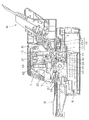
以下、図面を参照して本発明の実施形態について説明する。図1は、本実施形態にかかるドットインパクトプリンタ10の概観構成を示す斜視図であり、図2は、その側断面図である。ドットインパクトプリンタ10は、記録ヘッド20が備える記録ワイヤを、インクリボンを介してシートに押し付け、シート上にドットを形成することにより、文字を含む画像を記録するものである。ここで、シートとしては、所定長さに切断されたカットシートと、複数枚が連接された連続シートとがある。カットシートとしては、例えば単票紙や単票複写紙などの普通紙の他、通帳や葉書、封筒などがあり、連続シートとしては連続シートとしては連続紙、連続複写紙がある。
【0023】
さて、ドットインパクトプリンタ10は、大別すると、プリンタ本体11と、プッシュトラクタユニット12と、シート供給ガイド13と、給紙装置(CSF:カットシートフィーダ)14と、プリンタ本体11の上方、下方をそれぞれ覆うアッパケース15およびロアケース16とを備えている。
【0024】
プリンタ本体11は、記録ヘッド20およびキャリッジ21からなる記録機構部と、シート案内24、プラテン25および第1〜第4搬送ローラ26〜29からなるシート搬送機構部とから概略構成されている。
【0025】
プリンタ本体11は、本体フレームとしてのベースフレーム40およびリアフレーム41の略両端に、左サイドフレーム42および右サイドフレーム(不図示)がそれぞれ立設して固定されている。この左サイドフレーム42と右サイドフレームの間には、キャリッジガイド軸43およびプラテン25が回転可能に支持され、また、シートを案内するシート案内24が支持されている。
【0026】
また、キャリッジガイド軸43には、記録ヘッド20を搭載したキャリッジ21が、その軸方向に移動可能に支持されている。
【0027】
キャリッジ21は、図示せぬキャリッジ駆動用モータによりタイミングベルトを介してキャリッジガイド軸43の軸方向に駆動される。これにより、記録ヘッド20は、キャリッジガイド軸43の軸方向と一致する主走査方向に駆動される。また、キャリッジ21には、インクリボンカセット44が着脱自在に装着される。インクリボンカセット44のインクリボンは、記録ヘッド20とプラテン25との間に引き回される。
【0028】
記録ヘッド20は、多数の記録ワイヤ(不図示)を備え、これらの記録ワイヤの突出方向前方に、インクリボンが位置する。記録ヘッド20は、キャリッジ21と共に主走査方向に走行される間に、記録ワイヤを突出させてインクリボンに打ち当て、このインクリボンのインクを、プラテン25と記録ヘッド20との間に搬送されるシート(カットシート又は連続シート)に付着させて、このシートに文字を含む画像を記録する。
【0029】
また、プリンタ本体11には、上下に対となってシート案内24上のシートを搬送する第1搬送ローラ26および第2搬送ローラ27と、第3搬送ローラ28および第4搬送ローラ29とが配置されている。このうち、シート案内24の下方にある第1搬送ローラ26と、シート案内24の上方にある第4搬送ローラ29とが駆動ローラであり、第2搬送ローラ27および第3搬送ローラ28が従動ローラとなっている。すなわち、第1搬送ローラ26および第4搬送ローラ29の軸端には歯車が設けられており、この歯車を含む歯車輪列(不図示)が、例えば、左サイドフレーム42に配置されている。そして、この歯車輪列の一の歯車には、シート搬送モータ(不図示)のモータピニオンがかみ合っている。これにより、シート搬送モータを正転または逆転することによって、シートをプリンタ本体11の前方から後方へ搬送したり、プリンタ本体11の後方から前方へ搬送する。
【0030】
プッシュトラクタユニット12は、連続シートをシート案内24に供給するものであり、左右一対のトラクタ46を有している。トラクタ46は、トラクタ駆動プーリ45と、トラクタ従動プーリ47と、これらプーリ45、47に架け渡されたトラクタベルト48とから構成される。トラクタ駆動プーリ45の軸は、シート搬送モータのモータピニオンと噛み合う歯車輪列に噛み合っており、これにより、シート搬送モータが回転すると、トラクタ駆動プーリ45が回転し、トラクタベルト48によって連続シートがシート案内24に供給される。
【0031】
シート供給ガイド13は、プリンタ本体11の前側において、アッパケース15に着脱自在に装着され、シートを案内する。このシート供給ガイド13は、プリンタ本体11の前方からカットシートを手差し給紙する手差しトレイとして機能すると共に、プリンタ本体11の後方から給紙されたシート(カットシート及び連続シート)の排紙トレイとしても機能する。
【0032】
給紙装置14は、プリンタ本体11の後方側に着脱可能に装着され、カットシートを1枚ずつ給紙するものであり、次いで、この構成について詳述する。図3は、給紙装置14の斜視図である。この図に示すように、給紙装置14は、スライダ軸60の軸方向に移動可能に支持され、シート幅を規制するスライダ61と、ホッパ軸62の軸方向に移動可能に支持されるホッパ63と、給紙ローラ軸64の軸方向に移動可能に支持され、給紙ローラカバー69に覆われた給紙ローラ65とを左右に一組ずつ有している。
【0033】
ホッパ軸62は、スライダ軸60と給紙ローラ軸64との間に配置され、スライダ軸60と給紙ローラ65との間を図示せぬ駆動機構により平行移動可能に構成されている。また、ホッパ63は、図示せぬバネによって給紙ローラ65側に付勢されており、このホッパ63と給紙ローラ65との間にセットされたカットシートの束を給紙ローラ65に当接させる構成となっている。給紙ローラ軸64は、プリンタ本体11のシート搬送モータによって回転され、給紙ローラ65が回転することにより、カットシートが図中略斜め下方向に搬送され、プリンタ本体11へと導かれる。
【0034】
以上の構成の下、記録ヘッド20による記録動作は、キャリッジ21が主走査方向に走行される間に、記録ヘッド20の記録ワイヤにより一行分の記録がなされ、この一行分の記録がなされる度に、シートがカットシートの場合には、シート搬送機構部(プラテン25、第1搬送ローラ26、第2搬送ローラ27、第3搬送ローラ28及び第4搬送ローラ29)が、またシートが連続シートの場合には、シート搬送機構部及びプッシュトラクタユニット12が、それぞれシートを所定長(通常行間分)搬送させ、これらの動作が繰り返されることにより実施される。
【0035】
上述した記録ヘッド20、キャリッジ駆動モータ、シート搬送モータ及び後述するプラテンギャップ調整用モータ53の制御は、制御基板部100により実施される。この制御基板部100は、例えば、ロアケース16の中に収容されている。
【0036】
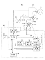
また、このプリンタ10には、供給されたシート(カットシート、連続シート)のシート厚に応じてキャリッジガイド軸43を回動させて、記録ヘッド20とプラテン25との間のプラテンギャップを調整するプラテンギャップ調整機構30が装備されている。ここで、図4は、プラテンギャップ調整機構30の構成を周辺構成と共に示す図である。プラテンギャップ調整機構30は、プラテンギャップ調整用モータ53、ロータリーエンコーダ50及び制御基板部100などから構成されている。
【0037】
図4に示すように、プラテンギャップ調整用モータ53は、ステッピングモータが用いられており、減速機構55を介してキャリッジガイド軸43に回転力を伝える。キャリッジガイド軸43には偏心軸が固定され、その間にキャリッジ21が配置される。これにより、プラテンギャップ調整用モータ53の回転により偏心軸が回転し、偏心軸の偏心量Lに対応する量(例えばL=1mmの場合には、2mm)だけキャリッジ21が図4中α方向に移動し、記録ヘッド20がプラテン25に対して前後移動する。この結果、記録ヘッド20とプラテン25との間の距離(プラテンギャップ)が変更される。ここで、記録ヘッド20の移動範囲は、プラテン25に当接する位置から、キャリッジ21がキャリッジ補助軸43aに当接して、その移動が規制される位置(基準位置)までである。このキャリッジ21の後側には、マイクロスイッチ58が配置されており、マイクロスイッチ58がオンになったか否かにより、記録ヘッド20が基準位置に位置したか否かが検出される。
【0038】
また、プラテンギャップ調整用モータ53の回転量は、ロータリーエンコーダ50によって検出される。ロータリーエンコーダ50は、プラテンギャップ調整用モータ53の軸53aに回転一体に設けられたスリット板56と、このスリット板56に対向して配置された、例えば発光ダイオード及びフォトダイオード等からなる投受光器57とから構成される。投受光器57の発光ダイオードから出射されてスリット板56のスリットを通過した光が、投受光器57のフォトダイオードに受光されてパルス信号に変換され、このパルス信号が制御基板部100に出力される。
【0039】
図4に示す制御基板部100において、制御部102は、ドットインパクトプリンタ10の各部を中枢的に制御するものであり、CPUを備えている。記憶部118は、制御部102によって実行される制御プログラムなどの各種プログラムや後述するプラテン温度特定テーブル120を記憶している。制御部102は、記憶部118に記憶されたプログラムに従って、印刷データに基づく印刷制御やプラテンギャップ調整制御、後述するプラテン温度の算出処理といった各種制御を行う。
【0040】
インターフェース(I/F)104は、制御部102の制御の下、通信ケーブル(不図示)を経由して接続されたコンピュータ(PC)との間で印刷データなどの各種データを送受信する。
【0041】
モータ駆動部106は、制御部102の制御の下、プラテンギャップ調整用モータ53、キャリッジ駆動用モータおよびシート搬送モータなどの各種モータに駆動パルスを供給し、各モータを回転駆動させる。
【0042】
記録ヘッド駆動部108は、制御部102の制御の下、記録ヘッド20を駆動して記録ワイヤを選択的に打ち出す。
【0043】
時間差検出部110は、ロータリーエンコーダ50からのパルス信号の周期とプラテンギャップ調整用モータ53の駆動パルスの周期との時間差を検出し、時間差積分部112に出力する。時間差積分部112は、入力した時間差の積分値を求め、当接判定部114に出力する。当接判定部114は、入力した積分値が予め設定した値、例えば、プラテンギャップ調整用モータ53の駆動パルスの周期の1/2以下(具体的には1.5ミリ秒など)に一致すると、記録ヘッド20がプラテン25またはシートに当接したと判断し、その旨を距離算出部116に通知する。
【0044】
距離算出部116は、マイクロスイッチ58からの信号受信を起点としてロータリーエンコーダ50からのパルス信号の計数を開始し、当接判定部114から当接が通知された時点の計数値を算出する。これにより、距離算出部116は、プラテン25上にシートが存在しない場合は、基準位置にある記録ヘッド20と、プラテン25との間のプラテンギャップ(以下、基準プラテンギャップという。)に相当するパルス計数値を算出する一方、プラテン25上にシートが存在する場合は、基準位置にある記録ヘッド20とシートとの間の距離に相当するパルス計数値を算出する。
【0045】
制御部102は、距離算出部116から、基準プラテンギャップの距離と、記録ヘッド20とシートとの間の距離を取得し、これら距離の差からシート厚を算出し、このシート厚を基準にしてプラテンギャップを調整する。
【0046】
なお、上述した距離算出部116などの各構成部は、図4に示すように、制御部102とは別体の回路などで構成されても良く、また、制御部102が各構成部の機能をソフトウェアによって実現する構成であっても良い。また、距離算出部116がロータリーエンコーダ50からのパルス信号を計数して距離を測定する場合について述べたが、プラテンギャップ調整用モータ53の駆動パルスを計数して距離を測定してもよい。
【0047】
ところで、記録ヘッド20とプラテン25との間のプラテンギャップ(基準プラテンギャップ)は、プラテン25や記録ヘッド20などの熱膨張によって値が変化する。従って、距離算出部116により計数されたパルス計数値は、プリンタ10の温度環境に応じて異なった値をとることとなる。ここで、図5は、プラテン25の温度が低温、常温、高温のときの基準プラテンギャップ測定時のパルス計数値を示す図である。より具体的には、図5は、プラテン温度が0℃〜10℃(低温)の場合の上記パルス計数値が330〜337パルスとなり、プラテン温度が10℃〜20℃(常温)の場合の上記パルス計数値が338〜345パルスとなり、プラテン温度が20℃〜30℃(高温)の場合の上記パルス計数値が346〜353パルスとなっている場合を示している。
【0048】
本実施形態では、基準プラテンギャップがプラテン温度と相関関係にあることに着目し、この相関関係の情報をプラテン温度特定テーブル120に記述しておき、このテーブル120に基づいて、距離算出部116が算出した基準プラテンギャップ測定時のパルス計数値からプラテン温度を推定する処理を行う。
【0049】
ここで、図6は、図5の場合におけるプラテン温度特定テーブル120の内容を示す図である。同図に示すように、プラテン温度特定テーブル120には、プラテン温度と、基準プラテンギャップ測定時のパルス計数値とが対応づけて格納されている。以下、このプラテン温度推定処理について説明する。
【0050】
図7は、プラテン温度推定処理を示すフローチャートである。この図に示すように、制御部102は、まず、基準位置にある記録ヘッド20とプラテン25との間のプラテンギャップ(基準プラテンギャップ)を測定する(ステップS1)。具体的には、制御部102は、モータ駆動部106を制御してキャリッジ21をマイクロスイッチ58がオンになる位置まで移動させた後、キャリッジ21を記録ヘッド20がプラテン25に当接する位置まで移動させる。これにより、キャリッジ21の移動に応じた数のパルス信号がロータリーエンコーダ50から出力され、距離算出部116は、当接判定部114により記録ヘッド20の当接が判定されたときのパルス計数値を制御部102に出力する。
【0051】
制御部102は、距離算出部116からパルス計数値を受け取ると、記憶部118に格納する(ステップS2)。なお、このパルス計数値は、記憶部118ではなく、制御部102の内部の図示しないRAMに格納してもよい。次いで、制御部102は、記憶部118に記憶されたプラテン温度特定テーブル120を参照し、距離算出部116から受け取ったパルス計数値に対応するプラテン温度を特定する(ステップS3)。例えば、パルス計数値が340の場合、制御部102は、プラテン温度が10℃〜20℃(常温)と判断する(図6参照)。これにより、制御部102は、プラテン温度が低温、常温、高温のいずれにあるかを推定することができる。なお、本実施形態では、プラテン温度を10℃単位の範囲で検出する場合について述べたが、さらに細かく若しくはさらに大まかに温度を特定するようにしてもよい。また、パルス計数値に基づいてプラテン温度を特定する場合について述べたが、プラテン温度特定テーブル120に、プラテン温度と、対応する基準プラテンギャップの距離とを対応づけて記述しておき、パルス計数値から算出した基準プラテンギャップの距離に基づいてプラテン温度を特定するようにしてもよい。
【0052】
さて、このようにして取得したプラテン温度は、プリンタ10に設けられた図示しない表示パネルに表示したり、コンピュータに送信して単にユーザに通知するようにしてもよいが、プラテンギャップの温度補償に使用してもよい。例えば、プラテン25の表面固さなどの特性がプラテン温度に応じて変化し、この特性変化を考慮してプラテンギャップを調整する必要がある場合は、以下のようにプラテンギャップを調整すればよい。以下、この場合の処理フローの一例を説明する。
【0053】
図8は、この場合のプラテンギャップ調整処理のフローチャートである。この図に示すように、制御部102は、まず、上記したプラテン温度推定処理を行い(ステップS10)、距離算出部116から基準プラテンギャップの距離を取得すると共に、プラテン温度を推定し、これらの値を記憶部118またはRAMに格納する。
【0054】
さて、このようにして基準プラテンギャップの距離とプラテン温度を取得すると、制御部102は、記録ヘッド20とシートとの間の距離を測定する(ステップS11)。具体的には、制御部102は、モータ駆動部106を制御して、シートを記録ヘッド20とプラテン25との間に搬送した後、キャリッジ21をマイクロスイッチ58がオンになる基準位置から記録ヘッド20がプラテン25上のシートに当接する位置まで移動させ、これにより、距離算出部116から該距離に対応するパルス計数値を取得する。
【0055】
次いで、制御部102は、上記測定した2つの距離のパルス計数値の差を算出することにより、シート厚を計算する(ステップS12)。ここで、キャリッジガイド軸43を一定角度回転させたときの記録ヘッド20の移動距離は、キャリッジガイド軸43の回転角度に応じて変化する。そこで、ロータリーエンコーダ50からのパルス信号の計数値と、移動距離との関係を記述したテーブルまたは近似式を記憶部118などに記憶させておき、制御部102は、その情報に基づいて上記差のパルス数からシート厚を計算する。
【0056】
そして、制御部102は、このシート厚を基準にして記録ヘッド20とシートとの距離を予め定めた値にするプラテンギャップを決定する(ステップS13)。上記したように、ここで決定したプラテンギャップは、プラテン25の表面固さなどの特性の温度変化に応じて修正する必要がある。そこで、プラテン温度と、プラテンギャップの補正量との関係を記述したテーブルまたは近似式を記憶部118などに記憶させておき、制御部102は、その情報に基づいて、ステップS10にて取得したプラテン温度から補正量を特定し、上記決定したプラテンギャップを補正する(ステップS14)。そして、制御部102は、補正後のプラテンギャップに調整すべく、モータ駆動部106を制御してプラテンギャップ調整用モータ53を駆動させ、プラテンギャップを調整する(ステップS15)。これにより、プラテン25の特性の温度変化を考慮してプラテンギャップを適切な値に調整することができ、この結果、広い温度範囲で記録品質を良好に維持することができる。
【0057】
以上説明したように、本実施形態によれば、温度センサを使用することなく、プラテン25の温度を推定することができる。これにより、本実施形態のプリンタ10は、温度センサを用いる従来のプリンタに比べて、部品点数を削減でき、組み立てを容易にすることができる。さらに、記録ヘッド20をプラテン25のシート配置領域に当接させて距離を測定するので、その領域の熱膨張などを正確に検出できる。従って、本実施形態のプリンタ10は、記録品質に関わる該領域の温度を精度良く測定することが可能である。
【0058】
以上、本発明を上記実施の形態に基づいて説明したが、本発明はこれに限定されるものではない。本実施形態では、プラテン温度特定テーブル120に基づいてプラテン温度を特定する場合について述べたが、プラテンギャップ測定値(パルス計数値など)とプラテン温度とを示す近似関係式に基づき、プラテン温度を特定するようにしてもよい。
【0059】
また、本実施形態では、プラテンギャップ(基準プラテンギャップ)の測定を一回しか行わない場合について述べたが、プラテンギャップを、プラテンの周方向及び桁方向に複数箇所に亘って測定し、これら測定値の平均値を算出するようにしてもよい。このようにすれば、プラテンギャップ測定値に対するプラテン25の加工上の誤差の影響を低減することができる。
【0060】
また、本実施形態では、記録ヘッド20を基準位置からプラテン25に当接する位置まで移動させてその間の距離を測定する場合について述べたが、プラテン25を移動可能に構成し、プラテン25を基準位置(上記実施形態で固定された位置)から記録ヘッド20に当接する位置まで移動させて該距離を測定するようにしてもよい。
【0061】
また、プラテンの温度を測定する場合に限らず、プリンタ10の内部温度を測定することも可能である。この場合、例えば、プリンタ10の内部温度と、プラテンギャップ測定値(パルス計数値など)とを対応づけた情報(テーブルなど)を記憶しておき、この情報に基づいて内部温度を特定するようにすればよい。
【0062】
また、上記実施形態では、円筒形プラテンについて説明したが、これに限定されず、例えば、平プラテンにも適用が可能である。また、ドットインパクトプリンタに適用する場合を説明したが、プラテンの温度制御が必要なホットメルトインクタイプのインクジェットプリンタなどの記録装置に広く適用が可能である。
【0063】
【発明の効果】
上述したように本発明によれば、温度センサを用いることなく、温度を測定することができる。
【図面の簡単な説明】
【図1】本発明の実施形態に係るドットインパクトプリンタの構成を示す斜視図である。
【図2】同プリンタの構成を示す側面図である。
【図3】同プリンタの給紙装置の外観を示す斜視図である。
【図4】同プリンタの機能的構成を周辺構成部と共に示す図である。
【図5】同プリンタのプラテンが低温、常温、高温のときのプラテンギャップ測定時のパルス計数値を示す図である。
【図6】プラテン温度特定テーブルを示す図である。
【図7】プラテン温度推定処理を示すフローチャートである。
【図8】プラテンギャップ調整処理のフローチャートである。
【符号の説明】
10 ドットインパクトプリンタ(記録装置)
20 記録ヘッド
21 キャリッジ
25 プラテン
30 プラテンギャップ調整機構
50 ロータリーエンコーダ
53 プラテンギャップ調整用モータ
100 制御基板部
102 制御部
116 距離算出部
118 記憶部
120 プラテン温度特定テーブル[0001]
TECHNICAL FIELD OF THE INVENTION
The present invention relates to a recording apparatus and a method for measuring the temperature thereof.
[0002]
[Prior art]
2. Description of the Related Art Conventionally, some recording apparatuses that record an image on a sheet or the like measure the temperature of a platen using a thermistor. For example, some dot impact printers measure the temperature of the platen to know the amount of thermal expansion of the platen in order to prevent the platen gap between the recording head and the platen from changing due to the thermal expansion of the platen. (For example, see Patent Document 1).
[0003]
In addition, in an inkjet printer of a type using a hot melt ink, since the temperature at which the ink is satisfactorily fixed varies depending on the type of the printing medium, the temperature of the platen is measured to control the temperature of the platen to the fixing temperature. (For example, see Patent Document 2).
[0004]
[Patent Document 1]
JP 2001-162891 A
[Patent Document 2]
JP-A-11-020144
[0005]
[Problems to be solved by the invention]
However, when a temperature sensor such as a thermistor is used, the number of components of the recording apparatus increases, which is disadvantageous in cost reduction. Further, the necessity of assembling the temperature sensor complicates the assembly work. is there.
[0006]
In addition, since the platen functions as a sheet placing member, it is preferable that the platen temperature is measured by measuring the temperature of the sheet placement region of the platen. However, it is difficult to arrange the temperature sensor in the sheet arrangement area of the platen due to the close contact of the sheet with the contact type temperature sensor. For example, even if the non-contact type sensor is used, there is no empty space. Can be difficult.
[0007]
The present invention has been made in view of the above circumstances, and has as its object to provide a recording apparatus capable of measuring a temperature without using a temperature sensor and a method of measuring the temperature.
[0008]
[Means for Solving the Problems]
In order to solve the above-mentioned problem, an invention according to
[0009]
According to a second aspect of the present invention, in the configuration of the first aspect, the temperature estimating means stores information on a temperature change characteristic of a measured value of a distance between the recording head and the platen in the platen gap adjusting means. A storage unit that estimates a temperature from the measured value of the distance based on information stored in the storage unit.
[0010]
According to a third aspect of the present invention, in the configuration according to the second aspect, the information stored in the storage unit includes information on a distance between the recording head and the platen measured by the platen gap adjustment unit at various temperatures. It is a table in which each measured value and the corresponding platen temperature are described in association with each other.
[0011]
According to a fourth aspect of the present invention, in the configuration according to any one of the first to third aspects, the distance measuring means moves the recording head from a reference position to a position in contact with a platen. Is measured as the distance between the recording head and the platen.
[0012]
According to a fifth aspect of the present invention, in the configuration according to the fourth aspect, the distance measuring means includes a pulse signal output means for outputting a pulse signal in accordance with the movement of the recording head; And a counting means for counting the number of pulses of the pulse signal when the pulse signal is moved to a position where the pulse signal comes into contact with the platen.
[0013]
According to a sixth aspect of the present invention, in the configuration according to any one of the first to fifth aspects, the distance measuring means measures a distance between a recording head and a platen at a plurality of positions on the platen, An average value of the measured values is calculated as the distance.
[0014]
According to a seventh aspect of the present invention, in the configuration according to any one of the first to sixth aspects, there is provided a platen gap adjusting mechanism for adjusting a platen gap between the recording head and the platen. The distance measuring means measures a distance between a recording head and a platen.
[0015]
According to an eighth aspect of the present invention, there is provided a temperature measuring method for a recording apparatus for recording an image via a recording head on a sheet disposed between the recording head and a platen, wherein a distance between the recording head and the platen is measured. And a temperature estimating step of estimating a temperature based on the measured value of the measured distance.
[0016]
According to a ninth aspect of the present invention, in the configuration according to the eighth aspect, in the temperature estimating step, the measured value of the distance between the recording head and the platen in the platen gap adjusting unit is stored in the storage unit. The platen temperature is estimated from a measured value of the distance between the recording head and the platen based on information on the temperature change characteristic.
[0017]
According to a tenth aspect of the present invention, in the configuration according to the ninth aspect, the information stored in the storage unit includes information on a distance between the recording head and the platen measured by the platen gap adjustment unit at various temperatures. It is a table in which each measured value and the corresponding platen temperature are described in association with each other.
[0018]
According to an eleventh aspect of the present invention, in the configuration according to any one of the eighth to tenth aspects, in the distance measuring step, the recording head is moved from a reference position to a position in contact with a platen. The distance is measured as a distance between a recording head and a platen.
[0019]
According to a twelfth aspect of the present invention, in the configuration according to the eleventh aspect, in the distance measuring step, when the recording head is moved from a reference position to a position in contact with a platen, the recording head is moved. And counting the number of pulses of the pulse signal output by the control unit.
[0020]
According to a thirteenth aspect of the present invention, in the configuration according to any one of the eighth to twelfth aspects, in the distance measuring step, a distance between a recording head and a platen is measured at a plurality of positions on the platen; The average value of each measured value is calculated as the distance.
[0021]
According to a fourteenth aspect of the present invention, in the configuration according to any one of the eighth to thirteenth aspects, the recording apparatus has a platen gap adjusting mechanism for adjusting a platen gap between a recording head and a platen, In the distance measuring step, the platen gap adjusting mechanism measures a distance between the recording head and the platen.
[0022]
BEST MODE FOR CARRYING OUT THE INVENTION
Hereinafter, embodiments of the present invention will be described with reference to the drawings. FIG. 1 is a perspective view showing an outline configuration of a
[0023]
The
[0024]
The printer main body 11 is schematically composed of a recording mechanism section including a
[0025]
In the printer main body 11, a
[0026]
The
[0027]
The
[0028]
The
[0029]
The printer main body 11 also includes a
[0030]
The
[0031]
The
[0032]
The
[0033]
The
[0034]
Under the above configuration, the recording operation by the
[0035]
The control of the
[0036]
Further, in the
[0037]
As shown in FIG. 4, a stepping motor is used as the platen
[0038]
The rotation amount of the
[0039]
In the
[0040]
The interface (I / F) 104 transmits and receives various data such as print data to and from a computer (PC) connected via a communication cable (not shown) under the control of the
[0041]
Under the control of the
[0042]
The recording
[0043]
The time difference detection unit 110 detects a time difference between the cycle of the pulse signal from the
[0044]
The
[0045]
The
[0046]
Each of the components such as the
[0047]
The value of the platen gap (reference platen gap) between the
[0048]
In the present embodiment, attention is paid to the fact that the reference platen gap is correlated with the platen temperature, and information on the correlation is described in the platen temperature specification table 120, and based on this table 120, the distance calculation unit 116 A process for estimating the platen temperature from the calculated pulse count value at the time of measuring the reference platen gap is performed.
[0049]
Here, FIG. 6 is a diagram showing the contents of the platen temperature identification table 120 in the case of FIG. As shown in the figure, the platen temperature specification table 120 stores the platen temperature and the pulse count value at the time of measuring the reference platen gap in association with each other. Hereinafter, the platen temperature estimation processing will be described.
[0050]
FIG. 7 is a flowchart showing the platen temperature estimation process. As shown in this figure, the
[0051]
Upon receiving the pulse count value from the
[0052]
The platen temperature obtained in this manner may be displayed on a display panel (not shown) provided in the
[0053]
FIG. 8 is a flowchart of the platen gap adjustment processing in this case. As shown in this figure, the
[0054]
When the distance of the reference platen gap and the platen temperature are acquired in this way, the
[0055]
Next, the
[0056]
Then, the
[0057]
As described above, according to the present embodiment, the temperature of the
[0058]
As described above, the present invention has been described based on the above embodiment, but the present invention is not limited to this. In the present embodiment, the case where the platen temperature is specified based on the platen temperature specification table 120 has been described. However, the platen temperature is specified based on an approximate relational expression indicating a platen gap measurement value (such as a pulse count value) and the platen temperature. You may make it.
[0059]
In the present embodiment, the case where the measurement of the platen gap (reference platen gap) is performed only once has been described. However, the platen gap is measured at a plurality of locations in the circumferential direction and the girder direction of the platen. An average value may be calculated. By doing so, it is possible to reduce the influence of an error in processing the
[0060]
Further, in the present embodiment, the case where the
[0061]
Further, the present invention is not limited to measuring the temperature of the platen, but can also measure the internal temperature of the
[0062]
In the above embodiment, the cylindrical platen has been described. However, the present invention is not limited to this, and is applicable to, for example, a flat platen. Further, the case where the present invention is applied to a dot impact printer has been described. However, the present invention can be widely applied to a recording apparatus such as a hot-melt ink type ink-jet printer which requires temperature control of a platen.
[0063]
【The invention's effect】
As described above, according to the present invention, the temperature can be measured without using a temperature sensor.
[Brief description of the drawings]
FIG. 1 is a perspective view illustrating a configuration of a dot impact printer according to an embodiment of the present invention.
FIG. 2 is a side view illustrating the configuration of the printer.
FIG. 3 is a perspective view illustrating an appearance of a sheet feeding device of the printer.
FIG. 4 is a diagram showing a functional configuration of the printer together with peripheral components.
FIG. 5 is a diagram illustrating pulse count values when a platen gap is measured when the platen of the printer is at low, normal, and high temperatures.
FIG. 6 is a diagram showing a platen temperature specification table.
FIG. 7 is a flowchart illustrating a platen temperature estimation process.
FIG. 8 is a flowchart of a platen gap adjustment process.
[Explanation of symbols]
10 dot impact printer (recording device)
20 Recording head
21 carriage
25 Platen
30 Platen gap adjustment mechanism
50 Rotary encoder
53 Platen gap adjustment motor
100 control board
102 control unit
116 Distance calculator
118 Memory
120 Platen temperature specification table
Claims (14)
記録ヘッドとプラテンとの間の距離を測定する距離測定手段と、
前記距離測定手段が測定した距離の測定値に基づいて温度を推定する温度推定手段とを備えることを特徴とする記録装置。In a recording apparatus that records an image via a recording head on a sheet disposed between a recording head and a platen,
Distance measuring means for measuring the distance between the recording head and the platen,
And a temperature estimating means for estimating a temperature based on a measured value of the distance measured by the distance measuring means.
当該プラテンギャップ調整手段における記録ヘッドとプラテンとの間の距離測定値の温度変化特性に関する情報が記憶される記憶手段を有し、
前記記憶手段に記憶された情報に基づいて、前記距離の測定値から温度を推定することを特徴とする請求項1に記載の記録装置。The temperature estimating means includes:
A storage unit in which information on a temperature change characteristic of a distance measurement value between the recording head and the platen in the platen gap adjustment unit is stored,
2. The recording apparatus according to claim 1, wherein a temperature is estimated from a measured value of the distance based on information stored in the storage unit.
前記記録ヘッドの移動に応じてパルス信号を出力するパルス信号出力手段と、
前記記録ヘッドが基準位置からプラテンに当接する位置まで移動したときの前記パルス信号のパルス数を計数する計数手段とを有することを特徴とする請求項4に記載の記録装置。The distance measuring means,
Pulse signal output means for outputting a pulse signal in accordance with the movement of the recording head,
5. The recording apparatus according to claim 4, further comprising a counting unit that counts the number of pulses of the pulse signal when the recording head moves from a reference position to a position where the recording head comes into contact with the platen.
このプラテンギャップ調整機構が、前記距離測定手段として、記録ヘッドとプラテンとの間の距離を測定することを特徴とする請求項1乃至6のいずれかに記載の記録装置。Having a platen gap adjustment mechanism to adjust the platen gap between the recording head and the platen,
7. The recording apparatus according to claim 1, wherein the platen gap adjusting mechanism measures a distance between a recording head and a platen as the distance measuring unit.
記録ヘッドとプラテンとの間の距離を測定する距離測定ステップと、
測定した距離の測定値に基づいて温度を推定する温度推定ステップとを実行することを特徴とする温度測定方法。In a temperature measurement method of a recording apparatus that records an image via a recording head on a sheet disposed between a recording head and a platen,
A distance measuring step of measuring a distance between the recording head and the platen;
A temperature estimating step of estimating a temperature based on a measured value of the measured distance.
前記距離測定ステップにおいては、このプラテンギャップ調整機構が、記録ヘッドとプラテンとの間の距離を測定することを特徴とする請求項8乃至13のいずれかに記載の温度測定方法。The recording apparatus has a platen gap adjustment mechanism for adjusting a platen gap between the recording head and the platen,
14. The temperature measuring method according to claim 8, wherein in the distance measuring step, the platen gap adjusting mechanism measures a distance between the recording head and the platen.
Priority Applications (1)
| Application Number | Priority Date | Filing Date | Title |
|---|---|---|---|
| JP2002373831A JP2004202824A (en) | 2002-12-25 | 2002-12-25 | Recording device and its temperature measurement method |
Applications Claiming Priority (1)
| Application Number | Priority Date | Filing Date | Title |
|---|---|---|---|
| JP2002373831A JP2004202824A (en) | 2002-12-25 | 2002-12-25 | Recording device and its temperature measurement method |
Publications (1)
| Publication Number | Publication Date |
|---|---|
| JP2004202824A true JP2004202824A (en) | 2004-07-22 |
Family
ID=32812012
Family Applications (1)
| Application Number | Title | Priority Date | Filing Date |
|---|---|---|---|
| JP2002373831A Pending JP2004202824A (en) | 2002-12-25 | 2002-12-25 | Recording device and its temperature measurement method |
Country Status (1)
| Country | Link |
|---|---|
| JP (1) | JP2004202824A (en) |
Cited By (1)
| Publication number | Priority date | Publication date | Assignee | Title |
|---|---|---|---|---|
| JP2021149277A (en) * | 2020-03-17 | 2021-09-27 | 株式会社リコー | Temperature control device, temperature control system, temperature control method, and program |
-
2002
- 2002-12-25 JP JP2002373831A patent/JP2004202824A/en active Pending
Cited By (2)
| Publication number | Priority date | Publication date | Assignee | Title |
|---|---|---|---|---|
| JP2021149277A (en) * | 2020-03-17 | 2021-09-27 | 株式会社リコー | Temperature control device, temperature control system, temperature control method, and program |
| JP7452134B2 (en) | 2020-03-17 | 2024-03-19 | 株式会社リコー | Temperature control device, temperature control system, temperature control method, and program |
Similar Documents
| Publication | Publication Date | Title |
|---|---|---|
| US7934882B2 (en) | Printer with sheet sending mechanism | |
| JP3687634B2 (en) | Printer | |
| US8668300B2 (en) | Image recording apparatus | |
| US8072622B2 (en) | Printer, and method for controlling print controller | |
| JP2007161389A (en) | Paper carrying mechanism, recorder and control method of paper carrying mechanism | |
| US8690315B2 (en) | Image recording apparatus and image recording method | |
| JP2010235217A (en) | Image recorder | |
| JP2003251904A (en) | Ribbon cartridge of recorder, and recorder | |
| EP0958923A2 (en) | Multipurpose printing apparatus | |
| JP2004202824A (en) | Recording device and its temperature measurement method | |
| JP4367609B2 (en) | Carriage and liquid ejecting apparatus provided with the carriage | |
| JP7082450B2 (en) | Printing device and control method of printing device | |
| JP2004202825A (en) | Recording device, platen gap adjustment mechanism, and platen gap adjustment method | |
| JP2002310613A (en) | Measurement system, printer sheet carrying control method for printer, and linear encoder used for the carrying control | |
| US7483668B2 (en) | Method for achieving accurate page margins on a media and duplex imaging apparatus thereof | |
| JP2008201067A (en) | Stamping device | |
| JP4348959B2 (en) | Platen gap adjustment device | |
| JP2004255653A (en) | Recording device and its control method | |
| JP2004202704A (en) | Recording device, platen gap adjustment method, platen gap adjustment device, and its control method | |
| JP4161661B2 (en) | Recording apparatus and control method thereof | |
| JP2011051218A (en) | Image recording apparatus | |
| JP2005067020A (en) | Instrument for measuring thickness of sheet, recorder, control method of instrument for measuring thickness of sheet, and control method of recorder | |
| JP2004050539A (en) | Platen gap adjuster, and recorder | |
| JP2004202735A (en) | Platen gap adjustment mechanism, platen gap adjustment method and recording device | |
| JP2003266826A (en) | Medium measuring instrument and recorder |