JP2004202803A - Liquid drop ejector and recorder using liquid drop ejector - Google Patents
Liquid drop ejector and recorder using liquid drop ejector Download PDFInfo
- Publication number
- JP2004202803A JP2004202803A JP2002373503A JP2002373503A JP2004202803A JP 2004202803 A JP2004202803 A JP 2004202803A JP 2002373503 A JP2002373503 A JP 2002373503A JP 2002373503 A JP2002373503 A JP 2002373503A JP 2004202803 A JP2004202803 A JP 2004202803A
- Authority
- JP
- Japan
- Prior art keywords
- droplet discharge
- liquid
- discharge device
- mist
- suction hole
- Prior art date
- Legal status (The legal status is an assumption and is not a legal conclusion. Google has not performed a legal analysis and makes no representation as to the accuracy of the status listed.)
- Pending
Links
Images


Abstract
Description
【0001】
【発明の属する技術分野】
本発明は、液滴吐出装置及び該液滴吐出装置を用いた記録装置に関し、さらに詳しくは、記録媒体上に液滴を飛翔させ記録を行うインクジェット記録装置、DNAチップ製造装置、カラーフィルタ製造装置等に用いられ、液滴吐出時に発生する液ミストを除去することができる液滴吐出装置及び該液滴吐出装置を用いた記録装置に関する。
【0002】
【従来の技術】
少量の液を移送するマイクロポンプを使用した液滴吐出装置の例として、インクジェット記録装置、レジスト塗布装置、DNAチップ製造装置、カラーフィルタ製造装置等が知られている。以下、従来の液滴吐出装置について、インクジェット記録装置を例にして説明する。
今日、一般的に用いられているインクジェット記録方式のインク吐出方法には、インク滴を吐出するために用いられる吐出エネルギー発生素子として電気熱変換素子を利用する方法と、圧電素子を利用する方法があり、いずれも電気的な信号によってインク滴の吐出を制御することが可能である。
【0003】
電気熱変換素子を用いるインク滴吐出方法の原理は、電気熱変換素子に電気信号を与えることにより、電気熱変換素子近傍のインクを瞬時に沸騰させ、そのときのインクの相変化により生じる急激な気泡の成長によってインク滴を高速に吐出させるものである。一方、圧電素子を用いるインク滴の吐出方法の原理は、圧電素子に電気信号を与えることにより、圧電素子を変位させ、この変位時の圧力によってインク滴を吐出させるものである。
【0004】
今日では、より高品位印字を達成するため、数plといったインク滴の小液滴化とそれに伴う吐出装置の高密度化が著しい。ところが、これらの記録装置では、小液滴化、高密度化に伴い、印字時に記録媒体に付着せず、雰囲気中に浮遊するインクミストが多く発生し、それが記録装置内部に飛散する。発生したインクミストは、記録装置内部のあらゆる所に付着し汚損する。その結果、記録媒体搬送系の汚れが直接記録媒体を汚すことで、画質を低下させるばかりか、電気部品への付着によるショート等の電気的トラブルや、摺動部等メカ部品への付着による機能劣化等の可能性がある。
【0005】
このため、記録装置本体には専用のファンとフィルタが設けられ、記録装置内の空気循環でインクミストの除去を行っているものもある。例えば、特許文献1に開示されたような、送風機を用いたインクミスト除去方法では、その風圧によって微小なインクミストが拡散してしまい、かえってインクミストの捕集効果を減ずることになる可能性がある。
また、特許文献2に開示されたような、インクジェットヘッドの動きによって発生する気流で、インクミストが記録装置内部に拡散することを防止する方法も提案されているが、インクジェットヘッド全体を気流確保のための筐体に納めなくてはならず、装置が大げさなものとなってしまう可能性がある。
【0006】
また一方で、特許文献3、4に開示されるような、記録ヘッド下の気流を一定に保つような工夫は、今日の微細化したインク滴、インクミストに対しては、過大な気流発生によるインク滴着弾位置のずれを引き起こし、印字品質を劣化させる原因になる等の可能性がある。
これに対し、特許文献5に開示されたものは、インクジェットヘッドのインク吐出口近くにインク吸入口を設けることで、効率よくインクミストを吸入しようとしているが、吸引ポンプを使用しているため、インク吐出ノズル部の気流を増速させてしまう可能性がある。
【0007】
図9は、特許文献5に開示された従来のインク吐出ヘッドを用いたインクジェット記録装置を破断して示す斜視図である。
従来のインクジェット方式の液滴吐出装置を用いたインクジェットプリンタは、ケーシング8内に長手方向に沿って設けられた記録媒体としての用紙28を矢印C方向(副走査方向)に間欠的に搬送する搬送装置30と、記録部10を用紙28の搬送方向に直交する矢印S方向(主走査方向)に往復移動させる記録部移動駆動部6とを備えている。ケーシング8には、送風ファン48とフィルタ49が設けられており、ケーシング内部の空気を外部へ導くようになっている。
【0008】
搬送装置30は、一対のローラユニット22a,22bと、一対のローラユニット24a,24bと、これらのローラユニットを駆動させる駆動部20とを備えている。これにより、用紙28が矢印C方向にそれぞれのローラユニットにより狭持されて間欠送りで搬送される。
記録部移動駆動部6は、所定の間隔をもって対向配置される回転軸に配されるプーリ26a,26bに巻掛けられるベルト16と、ローラユニット22a,22bに平行に配置され記録部10のキャリッジ部材10aの移動を平行に案内するガイドシャフト14と、キャリッジ部材10aに連結されるベルト16を順方向及び逆方向に駆動するモータ18とを備えている。モータ18が作動状態とされ、ベルト16が矢印S方向に回転されるとき、キャリッジ部材10aが同方向に所定の移動量だけ移動され、また、モータ18が作動状態とされてベルト16が失印S方向とは反対の方向に所定の移動量だけ移動される。
【0009】
さらに、記録部移動駆動部6の一端部には、キャリッジ部材10aのポームポジションとなる位置に、記録部10の吐出回復処理を行うための回復ユニット26が記録部10のインク吐出口配列に対向して設けられている。記録部10は図示しないフルカラー記録用の各色用に4個のインクジェットヘッドが設けられ、また各インクジェットヘッドにそれぞれ各色用のインクを供給するインクタンク12(12Y,12M,12C,12B)が着脱自在に備えられている。
【0010】
図10は、従来のインクジェットヘッドの要部を示す斜視図、図11は、同じく平断面図、図12は、図11のX−X断面図である。
インクジェットヘッド11は、インクタンクからのインク供給路としてのサブインクタンク40に固定される。図12に示す駆動基板32と、駆動基板32上に固定されるインク吐出口形成面部としてのオリフィスプレート部材34と、駆動基板32にフレキ38によって電気的に接続される電極プレート部材36とを備えている。フルカラー記録用のインクジェットヘッドの場合、サブインクタンク40、駆動基板32、オリフィスプレート部材34、電極プレート部材36等は、各色用に4組のヘッドが隣接して備えられる。また、インクジェットヘッド11は、例えば画素ピッチが42.35(μm)、1秒当たり最大8000画素の記録を行う場合、主走査方向の走査速度は、338.8(mm/s)とされる。電極プレート部材36には、インクジェットヘッド11が記録部10に装着されるとき、記録部10の電極部にそれぞれ電気的に接続される複数の電極部36aが配列されている。
【0011】
オリフィスプレート部材34には、図10における矢印A,B方向、すなわち主走査方向に直交する方向に沿って、n個のインク吐出口34ai(i=1〜n)、及び34bi(i=1〜n)が、それぞれ所定の間隔をもって2列平行に設けられている。また、インク吐出口34aiとインク吐出口34biとは、互いに対向する2つのインク吐出口間の中央に、例えば84.7/2(μm)ずれて配置される。すなわち、インク吐出口34aiとインク吐出口34biが互いに千鳥状に配置されている。各インク吐出口34ai,34biの形状は、例えば走査方向に沿う短辺(20μm)及び長辺(21μm)を有する長方形、楕円形とされる。もちろん円形であっても良い。
【0012】
各色のインク吐出口列34Y,34M,34C,34Bが並んだ主走査方向の端部には、スリット状の開口部をもつ吸入孔35a,35bが設けられ、吸入孔35a,35b内部の空間にはインクを吸収する吸着体31a,31bが収納され、どちらの吸入孔も流路37と連通している。また、流路37はチューブを介して吸引ポンプ等の負圧発生装置及びインクトラップに接続されている。
【0013】
駆動基板32は、例えばシリコンから形成され、図11、図12に示されるように、各色毎にサブインクタンク40の内側にテーパ状に開口する開口部としてのインク供給口32aが、オリフィスプレート部材34におけるn個のインク吐出口34aiとn個のインク吐出口34biとの間に対応した位置に、インク吐出口34aiの配列に沿って伸びて設けられている。インク供給口32aは、例えば、異方性のエッチングにより形成される。また、駆動基板32におけるオリフィスプレート部材34が固定される表面全体には、例えば窒化珪素(SiN)で作られた保護膜32fが形成されている。保護膜32fは、例えば、厚さ0.6μmに形成されている。
【0014】
駆動基板32における保護膜32fにより覆われる表面には、図12に示されるように、ヒータ部32ai及び32bi(i=1〜n)が所定のピッチ間隔、例えば84.7μm間隔でオリフィスプレート部材34におけるn個のインク吐出口34ai及び34bi(i=1〜n)に対向した位置に、それぞれ配されている。また、オリフィスプレート部材34のインク吐出口34ai,34biと保護膜32fとの間には、インク供給口32aを通じて供給されるインクをそれぞれ各ヒータ部32ai及び32biに導くインク分岐供給路42ai及び42bi(i=1〜n)がインク供給口32aを挟んで対称的に対向してオリフィスプレート部材34と一体に形成されて設けられている。
【0015】
従来のインクジェットヘッドにおいては、用紙28上に画像を形成するための吐出を行う際、インクジェットヘッド11と用紙28の間の空間では、インク滴とは別にインクミストが発生し、またインクジェットヘッド11の移動とともに、ミストを含む新たな空間が作られていく。ミスト発生の原因としては、インク滴の用紙28からのはね返りによるものと、インク滴と同時に吐出されるが用紙28に到達しない微細なインク滴が考えられる。
【0016】
図10に示す従来のインクジェットヘッドにおいては、インク滴吐出時に吸引ポンプ等の負圧発生手段を使用して吸入孔35a,35bから周囲の空気を吸引し、インクミストを空気とともに吸入孔35a,35bへ吸引し、インクミストを吸入孔内部の吸着体31a,31b、及び流路37、チューブを経てインクトラップに捕捉するものである。これにより、発生したインクミスは直ちに吸引され、ケーシング内に浮遊するインクミストは減少するものであるが、吸引ポンプ等の負圧発生手段を使用しているため、インク吐出部の気流を増速させ、インク滴の着弾点を不安定にする可能性があるといった問題がある。
【0017】
【特許文献1】
特開2000−238290号公報
【特許文献2】
特開平10―151731号公報
【特許文献3】
特開平7−25007号公報
【特許文献4】
特開2001−138548号公報
【特許文献5】
特開2000−255083号公報
【0018】
【発明が解決しようとする課題】
本発明は、前記した実情に鑑みてなされたもので、液滴吐出装置の液滴吐出時に、液滴とともに発生し雰囲気中に浮遊した液ミストをいち早くトラップすることで、装置内部に浮遊する液ミストを減少し、装置内部が汚損されるのを防止し、液滴が吐出される媒体を汚損することがない液滴吐出装置及び該液滴吐出装置を用いた記録装置を提供することを目的とする。
また、簡単な構成のミスト捕集機構によって、液ミストを高い捕集率で捕集することができ、メンテナンスが容易な液滴吐出装置及び該液滴吐出装置を低コストで提供することを目的とする。
【0019】
【課題を解決するための手段】
本発明は、上記課題を達成するため、液滴吐出装置及びインクジェット記録装置を、以下のように構成したことを特徴とするものである。
請求項1の発明は、液供給路と、該液供給路に連通する複数の液室と、該液室内の液を液滴として吐出するためのエネルギーを発生する複数の吐出エネルギー発生素子と、前記液滴を吐出する複数の液滴吐出口を有する液滴吐出装置において、前記複数の液滴吐出口の近傍に液ミストを吸入する吸入孔を設け、該吸入孔に前記液ミストを吸着する吸着体を充填するとともに、前記液ミストを前記吸入孔に導入する導入部材を設けることを特徴とする。
【0020】
請求項2の発明は、請求項1記載の液滴吐出装置において、前記導入部材は、前記吸入孔の近傍に設けられたじゃま板であることを特徴とする。
【0021】
請求項3の発明は、請求項2記載の液滴吐出装置において、前記じゃま板は、被液滴吐出媒体に対し主走査方向に移動する前記液滴吐出装置の移動方向上流側に設けられることを特徴とする。
【0022】
請求項4の発明は、請求項2記載の液滴吐出装置において、前記じゃま板は、被液滴吐出媒体が副走査方向に移動する前記液滴吐出装置の移動方向下流側に設けられることを特徴とする。
【0023】
請求項5の発明は、請求項1記載の液滴吐出装置において、前記導入部材は、前記吐出エネルギー発生素子と兼用し、該吐出エネルギー発生素子が発生する熱を前記吸入孔の周囲及び前記吸着体に伝達し、該吸着体内に上昇気流を発生させることを特徴とする。
【0024】
請求項6の発明は、請求項1乃至5記載の液滴吐出装置において、前記吸着体内を流動する液ミストの流速は、1m/秒以下、0.01m/秒以上であることを特徴とする。
【0025】
請求項7の発明は、請求項1乃至6記載の液滴吐出装置において、前記吸入孔は、前記複数の液滴吐出口の列状の並びと平行なスリット状に形成され、前記吸入孔の中央部の幅は端部の幅より広いことを特徴とする。
【0026】
請求項8の発明は、請求項1乃至6記載の液滴吐出装置において、前記吸入孔は、前記複数列の液滴吐出口の列状の並びと平行な複数のスリット状に形成され、前記吸入孔の中央部は端部より列数が多いことを特徴とする。
【0027】
請求項9の発明は、請求項1乃至8記載の液滴吐出装置において、前記複数の液滴吐出口の列は吐出液種毎に複数設けられるとともに、吐出液種毎に前記吸入孔及び前記じゃま板が設けられ、液ミスト同士の混合を起こさないことを特徴とする。
【0028】
請求項10の発明は、請求項1乃至9記載の液滴吐出装置において、前記吸着体は、前記吸入孔の液ミスト流入側から流出側に順に密度が粗から密に連続的または段階的に配列されていることを特徴とする。
【0029】
請求項11の発明は、請求項1乃至10記載の液滴吐出装置において、前記吸着体は、MEPAフィルタまたはHEPAフィルタ、あるいはその組み合わせからなることを特徴とする。
【0030】
請求項12の発明は、請求項1乃至5記載の液滴吐出装置において、前記吐出エネルギー発生素子は、電気熱変換体であることを特徴とする。
【0031】
請求項13の発明は、請求項1乃至4記載の液滴吐出装置において、吐出エネルギー発生素子は、電気機械変換体であることを特徴とする。
【0032】
請求項14の発明は、請求項1乃至13いずれかに記載の液滴吐出装置を用いた記録装置であることを特徴とする。
【0033】
本発明は、前記した構成に基づき、液滴吐出時に雰囲気中に浮遊した液ミストをいち早くトラップすることが可能となり、装置内部を浮遊する液ミストを減らし、装置内部が汚されるのを防止して、液ミストによる汚れの影響のない高品位な液滴吐出装置及び該液滴吐出装置を用いた記録装置を実現することができる。
【0034】
【発明の実施の形態】
以下、本発明の実施の形態を図1〜図8に示す実施例のインクジェット記録装置に基づいて説明する。
(実施例1)
図1は、本発明を適用した実施例1のサーマル方式の液滴吐出装置を用いたインクジェットヘッドの主要部を示す斜視図である。
図2は、同じくインクジェットヘッドの主要部を示す断面図で、図11のX−X断面図に相当する図である。なお、図1はフルカラーのインクジェットヘッドを示しているが、図2においては任意の1色のインクジェットヘッドについて示している。また、サーマル式のインクジェットヘッド11の主要部は、図10〜図12に示す従来のインクジェットヘッドと同様であるので、共通する部分については一部の説明を省略する。
実施例1のインクジェットヘッド11は、タンクからのインク供給路としてのサブインクタンク40に固定され、駆動基板32と、駆動基板32上に固定されるインク吐出口形成面部としてのオリフィスプレート部材34と、駆動基板32にフレキ38によって電気的に接続される電極プレート部材36とを備えている。
【0035】
オリフィスプレート部材34には、主走査方向に直交する方向に沿って、n個のインク吐出口34ai及び34bi(i=1〜n)が、それぞれ所定の間隔をもって2列平行に設けられている(なお、図2は図11のX−X断面図に相当するため、インク吐出口34biについては図示されていない)。また、インク吐出口34ai,34biは、互いに列方向に、例えば、84.7/2(μm)ずれて配置される。すなわち、インク吐出口34ai,34biが互いに千鳥状に配置されている。各インク吐出口34ai,34biの形状は、例えば、走査方向に沿う短辺(20μm)および長辺(21μm)を有する長方形、楕円形とされる。もちろん円形であっても良い。
【0036】
図1において、イエロー(Y)、マゼンタ(M)、シアン(C)、ブラック(B)のインク吐出口列34Y,34M,34C,34Bが並んだ主走査方向の両外方端には、インク吐出口列34Y,34Bに隣接して平行であって、略同様の長さのスリット状の開口部を有する吸入孔35a,35bが形成されている。吸入孔35a,35b内部の空間には液ミストを吸着する吸着体31a,31bが収納されている。
また、吸入孔35a,35bのさらに外方には、吸入孔35a,35bに平行で吸入孔35a,35bを十分に覆う長さのじゃま板50a,50bが形成されている。
【0037】
図2に示す単色のインクジェットヘッド11においては、矢印A方向においてのみインク滴を吐出して記録を行うので、インクジェットヘッド11の移動方向上流側にのみ吸入孔35とじゃま板50が設けられている。
インクジェットヘッド11が主走査方向の矢印A方向に移動し、用紙28上にインクを吐出して記録を行うとき、吸入孔35の近傍であって、移動方向の上流側にじゃま板50が形成されているので、じゃま板50の吸入孔35側の周囲の空気が圧縮される。したがって、吸入孔35の用紙28側(インク吐出口側)と吸入孔35の上側との間に圧力差が生じ、吸入孔35に収納された吸着体31内に空気の流れが発生する。
このとき、吸入孔35から周囲の空気が吸引されることになり、インクジェットヘッド11と用紙28の間の空間に発生したインク滴とは別のインクミストも空気流にしたがって吸引され、吸入孔35内部の吸収体31に、インクミストのほとんどが直ちに吸着除去されて、ケーシング8内に浮遊するインクミストは大きく減少するとともに、他色との混色を防止できる。
【0038】
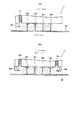
図3は、フルカラー記録装置のインクジェットヘッドに設けられた吸入孔がインクミストを吸引する様子を示す図である。
図3(A)に示すように、インクジェットヘッド11が矢印A方向(主走査方向)に移動する場合、じゃま板50は吸入孔35に対しインクジェットヘッド11の移動方向の上流側となる位置に設置されている。また、インクジェットヘッドが記録装置本体に固定され、用紙28が矢印C方向(副走査方向)に移動するライン型のインクジェット記録装置の場合、じゃま板50は吸入孔35に対し用紙28の移動方向の下流側となる位置に設置される。
また、図3(B)は、シャトル型と呼ばれ、インクジェットヘッドが主走査方向の往復方向移動時に液を吐出するインクジェットヘッドに関するもので、インクジェットヘッド11が矢印A方向及び矢印B方向に移動する際は、インクジェットヘッド11に往復動用のそれぞれのじゃま板50a及び50bを設ける。これにより、インクジェットヘッド11が矢印A方向に移動する際は、じゃま板50aによってインクミストを吸入孔35aに吸入し、矢印B方向に移動する際は、じゃま板50bによってインクミストを吸入孔35bに吸入することになる。
【0039】
一般に、用紙28とインクジェットヘッド11とが干渉することは好ましくなく、インクジェットヘッドの用紙との対向面を船底形状にした例が多いが、このような形状では、ヘッドと用紙の相対的な移動によって発生した気流が、液吐出口(ノズル)と用紙の最も狭い部分に向かって圧縮されることになり、この狭いギャップでの気流の流速が大きくなってしまう。このため、微小な液滴は気流の影響を受け、ミストの多発、着弾位置のずれによる品質の劣化を引き起こす。
これをさけるために、気流整流体を液吐出ノズル面と用紙との間に入る長さで設置しておくことで、ノズル面近傍の気流の乱れを防ぐことができる。最も単純には、板状の突起物を設けることで効果が出るが、用紙との対抗端を丸めることで、用紙と干渉した際の装置ダメージを小さくすることも可能である。
【0040】
(実施例2)
図4は、実施例2のサーマル方式の液滴吐出装置を用いたインクジェットヘッドの主要部を示す断面図である。
サーマル方式のインクジェットヘッドでは、そのヒータが発する熱がヘッド自体に蓄積してゆくため、吐出特性の変化やヒータ自体の劣化等様々な影響が発生する。そのため、熱伝導性の良い基板上にヘッドを形成し、放熱効果を上げるようにしている。本発明では、そのヒータが発する熱を利用し、多孔質部材からなる吸着体31自体を加熱する(ヘッドは冷却される)。インクジェットヘッドの発する熱を矢印H方向に伝達して吸入孔35の周囲及び吸着体31それ自体を加熱することによって、ミストの吸着体31に矢印に示すような上昇気流を発生させ、ミストの捕集効果をあげている。さらに、捕集されたミストは暖められ吸着しやすくすることで、たれ落ち等の影響も防止できる。
図には示してないが、ライン型と呼ばれるような大型の直線状インクジェットヘッドを用いる場合は、インクジェットヘッドから発する熱を、記録装置本体に固定されるフィルタ49部まで、ヒートパイプのような熱伝導性の高い部材で廃熱を運び放熱させることで、冷却性の向上に加えてフィルタ49でのミスト捕集効果を高めることも可能である。
【0041】
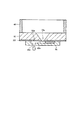
図5は、実施例3及び4のインクジェットヘッドの液吐出口列、吸入孔、じゃま板の配置を示す図、及び従来のインクジェットヘッドによるインクミストの発生分布を示す図である。
(実施例3)
図5(A)は、本発明の実施例3のインクジェットヘッドの部分を液吐出口側からみた底面図である。スリット状の吸入孔35の形状が中央部で幅広く、両端部で狭くなっている。図5(C)は、ミスト吸収機構を備えていない従来のインクジェットヘッドの液吐出口側からみた図である。図5(A)と図5(C)を比較することで理解されるように、インクジェットヘッド11と用紙28の間で発生する気流の影響でインクジェットヘッド中央付近でミストが巻き込まれてミストの密度が上昇していることがわかる。したがって、この中央付近の吸入口幅を図5(A)に示すように広くすることで、液ミストの捕集効果が向上する。
【0042】
(実施例4)
図5(B)は、実施例4のインクジェットヘッドの部分を液吐出口側からみた底面図である。
実施例4のインクジェットヘッド11で、図5(A)に示す実施例3のインクジェットヘッドと異なるのは、吸入孔35を1本のスリットで形成するのに代えて、複数本スリットで構成する点である。この場合でも実施例3で述べたインクジェットヘッドと組み合わせることでさらなる効果がある。各色のヘッド列間にも吸入孔35及びじゃま板50を設けることで、インクの混色を防ぎ、印字品質を向上することができる。この場合は、ライン型インクジェット記録装置との組み合わせや、定着液を使うような反応性液を使う場合ではさらなる効果がある。
【0043】
(実施例5)
図6は、本発明の実施例5の液滴吐出装置に用いる液ミストの吸着体を示す図である。
液ミストを吸引する吸入孔35には複数の吸着体が充填されるが、吸入孔35の流入側で吸着体31の密度が粗く、流出側にいく程吸着体の密度が密になっている。このような構成にすることで、吸着体内部の気流の流速を損ねることなく、液ミストを捕集できる。吸着体31の密度が粗であると、ミストの捕集効果が低く、ミストがそのまま筐体内あるいは、装置外へ流出してしまう。また密であると、吸入口近傍でミストが多量に捕集され、詰まりやすくなり吸着体の寿命が短くなる。
【0044】
図6(A)は、IES(Institute of Environmental Sciences)規格に規定されるHEPA(High Efficiency Particulate Air)フィルタ、MEPA(Middle Efficiency Particulate Air)フィルタを組み合わせて吸着体31とした例で、吸入側からプレフィルタ31a1、MEPAフィルタ31a2、HEPAフィルタ31a3の順に収納され、順に吸着体の密度が大となっている。
図6(B)は、グラスウール、フッ素樹脂ウール等の不織布フィルタからなり、吸入側に粗フィルタ31b1を配置し、密フィルタ31b2まで順次連続的あるいは段階的に密度を変化させて配置されている。
図6(C)は、発泡樹脂を用いたスポンジ状吸着体31cを利用した例である。多孔質体として、活性炭等との組み合わせでも同様の効果が得られる。
図6(D)は、開口サイズの異なる微細なハニカムメッシュを組み合わせて吸着体とした例である。ここでは3層の例31d1,31d2,31d3の積層状となっているが、より多層としても良いことは言うまでもない。また、金属材料を用いることでヘッドの放熱効果も向上する。これらは単独で使用する必要はなく、各構成の組み合わせであっても効果が変わることはない。
【0045】
(実施例6)
実施例6のインクジェットヘッドにおいては、ミストの吸着体31を通過する気流の速度を1m/秒以下、0.01m/秒以上としている。1m/秒以下の流速は、極微小なミストを高い捕捉率で捕集するために必要な流速である。今日のような微細な液滴を噴射する吐出装置においては、そのミストは粒径が1μmを下回るような微細なミストとなり、これを捕集するためには、高性能な捕集装置が必要となる。
【0046】
図7は、ミスト吸着体がミストを捕集する態様を示す図である。
吸着体31がミストMを捕集するメカニズムは、図7(A)に示すような、ミストの慣性による接触吸着、図7(B)に示すような、ミストが拡散することでの接触吸着、図7(C)に示すような、ミストの衝突による接触吸着があるが、粒径の小さいミストではその捕集メカニズムは拡散によるものが主となり、粒径の大きいものは慣性によるものが主となる。したがって、微細なミストMを吸着させるには拡散による捕集を効率よく行う必要があるので、吸着層を流れる気流の流速が重要となる。
【0047】
図8は、ミストの粒子径と透過率の関係を示す図である。
粒子径1μm程度のミストの捕集率を99.9%以上とするためには、1m/秒以下の流速でなくてはならない。より高清浄度が求められるようなクリーンルームや病院のような環境では、さらに遅い0.5m/秒以下の流速とすることが望ましい。ここで、流速は低いほど捕集率は高くなるが、一方ミストを含んだ空気の流量は少なくなるから、全体としてミストの捕集量が最も大きくなるような流速となるように流速の下限値を決定しなければならないが、一般的な濾材の場合0.01m/秒以下の流速では吸着効率が悪くなったり、吸入孔の開口面積を大きくしなければならなくなったりするので好ましくない。
【0048】
【発明の効果】
以上の記載から明らかなように、本発明によれば次のような効果を奏する。
(1)複数の液滴吐出口の近傍に液ミストを吸入する吸入孔を設け、吸入孔に液ミストを吸着する吸着体を充填するとともに、液ミストを吸入孔に導入する液ミスト導入部材を設けるので、液滴吐出時に雰囲気中に浮遊した液ミストをいち早くトラップすることが可能となり、装置内部を浮遊する液ミストを減らし、装置内部が汚されるのを防止して、液ミストによる汚れの影響のない高品質な液滴吐出装置を実現することができる。
【0049】
(2)液ミストを吸入孔に導入する手段として、吸入ポンプ等の負圧発生手段を用いず、じゃま板による空気圧縮を利用するので、構造が簡単で動作が確実であるとともに、長期にわたって保守が容易な液滴吐出装置及び記録装置を低コストで実現することができる。
【0050】
(3)液ミストを吸入孔に導入する手段として、吸入ポンプ等の負圧発生手段を用いず、液滴を吐出するために用いられるエネルギー発生手段が発生する熱を利用するので、構造が簡単で動作が確実であるとともに、長期にわたって保守が容易な液滴吐出装置及び記録装置を低コストで実現することができる。
【0051】
(4)液ミストの導入部材により前記吸入孔に導入される液ミストの流速は、1m/秒以下、0.01m/秒以上であるので、粒径が1μmを下回るような微細なミストを99.9%以上の高い捕捉率で捕集することができるとともに、0.01m/秒以上の流速であるため、一般的な濾材の場合においても吸着効率が悪くなることがない。
【0052】
(5)スリット状の吸入孔は、中央部の幅が端部の幅よりも広い、または中央部のスリット数が端部のスリット数より多いので、液滴吐出装置が液滴を吐出する際に付随的に発生する液ミストの発生分布と合致し、液ミストをスムーズに導入することができ、液ミストの捕集効果が向上する。
【0053】
(6)複数の液種を吐出する液滴吐出ヘッドが隣接して設置されている液滴吐出装置において、吸入孔及びじゃま板は、吐出液種毎につまり液滴吐出ヘッド毎に設けられているので、液ミスト同士の混合を起こさず、反応性の液ミストでも捕集した液ミストを容易に処理することができる。
【0054】
(7)液ミストを吸着する吸着体は、吸入孔のミスト流入側から流出側に順に密度が粗から密に無段階または段階的に配列されているので、吸着体内部の気流の流速を減殺することなくミストを捕集することができ、またミストの詰まりを防止することができ、吸着体の寿命を延ばすことができる。
また、吸着体としてMEPAフィルタやHEPAフィルタを使用することにより、1μmを下回る極めて微細な粒径のミストを高い捕集率で捕集することができる。
【0055】
(8)液滴吐出装置の構成要素である電気熱変換体(抵抗体素子)や電気機械変換体(ピエゾ素子)は、半導体形成技術を流用して作成することができ、小型高密度の液滴吐出装置を得ることが可能となる。
【図面の簡単な説明】
【図1】実施例1のサーマル方式の液滴吐出装置を用いたインクジェットヘッドの主要部を示す斜視図である。
【図2】インクジェットヘッドの主要部を示す断面図である。
【図3】インクジェットヘッドに設けられた吸引孔がインクミストを吸引する様子を示す図である。
【図4】実施例2のサーマル方式の液滴吐出装置を用いたインクジェットヘッドの主要部を示す断面図である。
【図5】実施例3,4の液滴吐出装置の液吐出口列、吸入孔、じゃま板の配置を示す図、及び従来のインクジェットヘッドによるインクミストの発生分布を示す図である。
【図6】実施例5の液滴吐出装置を用いる液ミストの吸着体を示す図である。
【図7】ミスト吸着体がミストを捕集する態様を示す図である。
【図8】ミストの粒子径と透過率の関係を示す図である。
【図9】従来のインク吐出ヘッドを用いたインクジェット記録装置を破断して示す斜視図である。
【図10】従来のインクジェットヘッドの要部を示す斜視図である。
【図11】従来のインクジェットヘッドの要部を示す平断面図である。
【図12】従来のインクジェットヘッドの要部を示す縦断面図である。
【符号の説明】
6…記録部移動駆動部、8…ケーシング、10…記録部、10a…キャリッジ部材、11…インクジェットヘッド、12…インクタンク、14…ガイドシャフト、16…ベルト、18…モータ、22a,22b…ローラユニット、24a,24b…ローラユニット、26…回復ユニット、26a,26b…プーリ、28…用紙、30…搬送装置、31…吸着体、32…駆動基板、32a…インク供給口、32ai,32bi…ヒータ部、32f…保護膜、34…オリフィスプレート部材、34ai,34bi…インク吐出口、34Y,34M,34C,34B…インク吐出口列、34ai,34bi…インク吐出口、35,35a,35b…吸入孔、36…電極プレート部材、36a…電極部、37…流路、38…フレキ、40…サブインクタンク、42ai,42bi…インク分岐供給路、8…送風ファン、49…フィルタ、50,50a,50b…じゃま板。[0001]
TECHNICAL FIELD OF THE INVENTION
The present invention relates to a droplet discharge device and a recording device using the droplet discharge device, and more particularly, to an ink jet recording device that performs recording by flying droplets on a recording medium, a DNA chip manufacturing device, and a color filter manufacturing device. The present invention relates to a droplet discharge device that can be used for removing liquid mist generated at the time of discharging a droplet, and a recording device using the droplet discharge device.
[0002]
[Prior art]
As an example of a droplet discharge device using a micropump for transferring a small amount of liquid, an ink jet recording device, a resist coating device, a DNA chip manufacturing device, a color filter manufacturing device, and the like are known. Hereinafter, a conventional droplet discharge device will be described using an ink jet recording device as an example.
2. Description of the Related Art In general, ink jet recording methods for ink jet recording that are used today include a method using an electrothermal transducer as a discharge energy generating element used for discharging ink droplets and a method using a piezoelectric element. In any case, the ejection of ink droplets can be controlled by an electric signal.
[0003]
The principle of the ink droplet ejection method using the electrothermal conversion element is that, by giving an electric signal to the electrothermal conversion element, the ink near the electrothermal conversion element is instantaneously boiled, and a sudden change caused by a phase change of the ink at that time occurs. Ink droplets are ejected at high speed by the growth of bubbles. On the other hand, the principle of the method of ejecting ink droplets using a piezoelectric element is to apply an electric signal to the piezoelectric element to displace the piezoelectric element and eject the ink droplet by the pressure at the time of this displacement.
[0004]
Nowadays, in order to achieve higher quality printing, the size of ink droplets, such as several pl, has been remarkably reduced, and the density of ejection devices has been significantly increased. However, with these recording apparatuses, as ink droplets are made smaller and higher in density, a large amount of ink mist that does not adhere to the recording medium during printing and floats in the atmosphere is generated and scatters inside the recording apparatus. The generated ink mist adheres and contaminates everywhere in the recording apparatus. As a result, contamination of the recording medium transport system directly contaminates the recording medium, which not only deteriorates image quality, but also causes electrical trouble such as short-circuit due to adhesion to electric components, and functions due to adhesion to sliding parts and other mechanical parts. There is a possibility of deterioration.
[0005]
For this reason, a recording apparatus main body is provided with a dedicated fan and a filter, and some of them remove ink mist by air circulation in the recording apparatus. For example, in the ink mist removal method using a blower as disclosed in Patent Document 1, the fine pressure of the ink mist may be diffused by the wind pressure, which may reduce the effect of collecting the ink mist. is there.
Also, a method has been proposed for preventing the ink mist from diffusing into the inside of the printing apparatus due to the air flow generated by the movement of the ink jet head, as disclosed in
[0006]
On the other hand, as disclosed in Patent Literatures 3 and 4, a device for maintaining a constant airflow under a print head is not suitable for today's fine ink droplets and ink mist due to excessive airflow. There is a possibility that the displacement of the ink droplet landing position may be caused to cause a deterioration in print quality.
On the other hand, the one disclosed in Patent Document 5 attempts to efficiently suck the ink mist by providing an ink suction port near the ink discharge port of the ink jet head, but uses a suction pump, There is a possibility that the airflow of the ink discharge nozzle portion is increased.
[0007]
FIG. 9 is a cutaway perspective view of an ink jet recording apparatus using a conventional ink ejection head disclosed in Patent Document 5.
An ink jet printer using a conventional ink jet type droplet discharge device conveys
[0008]
The
The recording unit moving drive unit 6 includes a
[0009]
Further, at one end of the recording unit moving drive unit 6, a
[0010]
10 is a perspective view showing a main part of a conventional ink jet head, FIG. 11 is a plan sectional view thereof, and FIG. 12 is a sectional view taken along line XX of FIG.
The
[0011]
The
[0012]
At the ends in the main scanning direction where the ink
[0013]
The
[0014]
As shown in FIG. 12, heater sections 32ai and 32bi (i = 1 to n) are provided at predetermined pitch intervals, for example, at an interval of 84.7 μm, on the surface of
[0015]
In the conventional inkjet head, when performing ejection for forming an image on the
[0016]
In the conventional ink jet head shown in FIG. 10, the surrounding air is sucked from the suction holes 35a and 35b by using a negative pressure generating means such as a suction pump when the ink droplets are ejected, and the ink mist is sucked together with the air into the suction holes 35a and 35b. The ink mist is trapped in the ink trap through the
[0017]
[Patent Document 1]
JP 2000-238290 A
[Patent Document 2]
Japanese Patent Application Laid-Open No. 10-151731
[Patent Document 3]
JP-A-7-25007
[Patent Document 4]
JP 2001-138548 A
[Patent Document 5]
JP-A-2000-255083
[0018]
[Problems to be solved by the invention]
The present invention has been made in view of the above-described circumstances, and when a droplet is discharged by a droplet discharge device, a liquid mist generated together with the droplet and floating in the atmosphere is quickly trapped, so that the liquid floating inside the device can be trapped. An object of the present invention is to provide a droplet discharge device that reduces mist, prevents contamination of the inside of the device, and does not pollute a medium from which droplets are discharged, and a recording device using the droplet discharge device. And
It is another object of the present invention to provide a droplet discharge device that can collect liquid mist at a high collection rate by a mist collection mechanism having a simple configuration and that is easy to maintain, and that the droplet discharge device is provided at low cost. And
[0019]
[Means for Solving the Problems]
According to the present invention, in order to achieve the above object, a droplet discharge device and an ink jet recording device are configured as follows.
The invention according to claim 1 is a liquid supply path, a plurality of liquid chambers communicating with the liquid supply path, a plurality of discharge energy generating elements for generating energy for discharging liquid in the liquid chamber as droplets, In a droplet discharge device having a plurality of droplet discharge ports for discharging the droplet, a suction hole for sucking a liquid mist is provided near the plurality of droplet discharge ports, and the liquid mist is sucked to the suction hole. An introduction member for filling the adsorbent and introducing the liquid mist into the suction hole is provided.
[0020]
According to a second aspect of the present invention, in the droplet discharge device according to the first aspect, the introduction member is a baffle provided near the suction hole.
[0021]
According to a third aspect of the present invention, in the droplet discharge device according to the second aspect, the baffle plate is provided on the upstream side in the movement direction of the droplet discharge device that moves in the main scanning direction with respect to the droplet discharge medium. It is characterized by.
[0022]
According to a fourth aspect of the present invention, in the droplet discharge device according to the second aspect, the baffle plate is provided on the downstream side in the moving direction of the droplet discharging device in which the droplet discharge medium moves in the sub-scanning direction. Features.
[0023]
According to a fifth aspect of the present invention, in the droplet discharge device according to the first aspect, the introduction member also serves as the discharge energy generating element, and transfers the heat generated by the discharge energy generating element around the suction hole and the suction. It is transmitted to the body and generates an updraft in the adsorbent.
[0024]
According to a sixth aspect of the present invention, in the droplet discharge device according to any one of the first to fifth aspects, a flow rate of the liquid mist flowing through the adsorbent is 1 m / sec or less and 0.01 m / sec or more. .
[0025]
According to a seventh aspect of the present invention, in the droplet discharge device according to any one of the first to sixth aspects, the suction hole is formed in a slit shape parallel to a row of the plurality of droplet discharge ports. The width of the central portion is wider than the width of the end portion.
[0026]
According to an eighth aspect of the present invention, in the droplet discharge device according to any one of the first to sixth aspects, the suction hole is formed in a plurality of slits parallel to a row of the plurality of rows of the droplet discharge ports. The central part of the suction hole is characterized by having more rows than the end part.
[0027]
According to a ninth aspect of the present invention, in the droplet discharge device according to any one of the first to eighth aspects, a plurality of rows of the plurality of droplet discharge ports are provided for each discharge liquid type, and the suction holes and the rows are provided for each discharge liquid type. A baffle plate is provided to prevent mixing of the liquid mist.
[0028]
According to a tenth aspect of the present invention, in the droplet discharge device according to any one of the first to ninth aspects, the adsorbent is continuously or stepwise densely and densely in order from the liquid mist inflow side to the outflow side of the suction hole. It is characterized by being arranged.
[0029]
According to an eleventh aspect of the present invention, in the droplet discharge device according to any one of the first to tenth aspects, the adsorbent includes a MEPA filter, a HEPA filter, or a combination thereof.
[0030]
According to a twelfth aspect of the present invention, in the droplet discharge device according to any one of the first to fifth aspects, the discharge energy generating element is an electrothermal transducer.
[0031]
According to a thirteenth aspect, in the droplet discharge device according to any one of the first to fourth aspects, the discharge energy generating element is an electromechanical transducer.
[0032]
According to a fourteenth aspect of the present invention, there is provided a recording apparatus using the droplet discharge device according to any one of the first to thirteenth aspects.
[0033]
According to the present invention, it is possible to quickly trap liquid mist floating in the atmosphere at the time of discharging droplets, reduce liquid mist floating inside the device, and prevent the inside of the device from being contaminated, based on the configuration described above. In addition, it is possible to realize a high-quality droplet discharge device free from the influence of contamination by liquid mist and a recording device using the droplet discharge device.
[0034]
BEST MODE FOR CARRYING OUT THE INVENTION
Hereinafter, embodiments of the present invention will be described based on the ink jet recording apparatus of the embodiment shown in FIGS.
(Example 1)
FIG. 1 is a perspective view showing a main part of an ink jet head using a thermal type droplet discharging apparatus according to a first embodiment to which the present invention is applied.
FIG. 2 is a cross-sectional view showing a main part of the ink-jet head, which corresponds to a cross-sectional view taken along line XX of FIG. Although FIG. 1 shows a full-color inkjet head, FIG. 2 shows an inkjet head of any one color. The main parts of the thermal type
The
[0035]
In the
[0036]
In FIG. 1, ink is provided at both outer ends in the main scanning direction in which yellow (Y), magenta (M), cyan (C), and black (B) ink
Further, outside the suction holes 35a and 35b,
[0037]
In the single-color
When the
At this time, ambient air is sucked from the
[0038]
FIG. 3 is a diagram illustrating a state in which a suction hole provided in an inkjet head of a full-color recording apparatus sucks ink mist.
As shown in FIG. 3A, when the
FIG. 3B relates to an ink jet head called a shuttle type, which discharges liquid when the ink jet head moves in a reciprocating direction in the main scanning direction. The
[0039]
In general, it is not preferable that the
In order to avoid this, by installing the airflow rectifier so as to have a length between the liquid discharge nozzle surface and the paper, it is possible to prevent turbulence in the airflow near the nozzle surface. In the simplest case, the effect is obtained by providing a plate-shaped projection. However, by rounding the end facing the sheet, it is also possible to reduce the damage to the apparatus when the sheet interferes with the sheet.
[0040]
(Example 2)
FIG. 4 is a cross-sectional view showing a main part of an ink jet head using the thermal droplet discharge device of the second embodiment.
In a thermal inkjet head, since the heat generated by the heater accumulates in the head itself, various effects such as a change in ejection characteristics and deterioration of the heater itself occur. For this reason, a head is formed on a substrate having good thermal conductivity so as to enhance the heat radiation effect. In the present invention, the heat generated by the heater is used to heat the adsorbent 31 itself made of a porous member (the head is cooled). The heat generated by the ink jet head is transmitted in the direction of arrow H to heat the area around the
Although not shown in the figure, when a large linear ink jet head called a line type is used, heat generated from the ink jet head is transferred to a
[0041]
FIG. 5 is a diagram showing the arrangement of the liquid ejection port arrays, suction holes, and baffles of the inkjet heads of Examples 3 and 4, and a diagram showing the distribution of ink mist generated by the conventional inkjet head.
(Example 3)
FIG. 5A is a bottom view of the portion of the inkjet head according to the third embodiment of the present invention as viewed from the liquid ejection port side. The shape of the slit-shaped
[0042]
(Example 4)
FIG. 5B is a bottom view of the portion of the inkjet head of the fourth embodiment as viewed from the liquid ejection port side.
The
[0043]
(Example 5)
FIG. 6 is a diagram illustrating a liquid mist adsorbent used in the droplet discharge device according to the fifth embodiment of the present invention.
The
[0044]
FIG. 6A shows an example in which an adsorbent 31 is formed by combining a HEPA (High Efficiency Particulate Air) filter and a MEPA (Middle Efficiency Particulate Air) filter defined by the IES (Institute of Environmental Sciences) standard. Pre-filter 31a 1 ,
FIG. 6B shows a nonwoven fabric filter made of glass wool, fluororesin wool, or the like, and a
FIG. 6C shows an example in which a sponge-like adsorbent 31c using a foamed resin is used. Similar effects can be obtained by combining the porous body with activated carbon or the like.
FIG. 6D shows an example in which fine honeycomb meshes having different opening sizes are combined to form an adsorbent. Here is an example of three
[0045]
(Example 6)
In the ink jet head according to the sixth embodiment, the speed of the airflow passing through the adsorbent 31 of the mist is set to 1 m / sec or less and 0.01 m / sec or more. The flow rate of 1 m / sec or less is a flow rate necessary for collecting a very small mist at a high capture rate. In today's discharge devices that eject fine droplets, the mist is a fine mist having a particle diameter of less than 1 μm, and a high-performance collection device is required to collect the mist. Become.
[0046]
FIG. 7 is a diagram illustrating an aspect in which the mist adsorbent collects mist.
The mechanism by which the adsorbent 31 collects the mist M includes contact adsorption by mist inertia as shown in FIG. 7A, contact adsorption by diffusion of the mist as shown in FIG. As shown in FIG. 7C, there is contact adsorption due to mist collision. However, in the case of mist having a small particle size, the trapping mechanism is mainly based on diffusion, and the one having a large particle size is mainly based on inertia. Become. Therefore, in order to adsorb the fine mist M, it is necessary to efficiently collect the mist M by diffusion. Therefore, the flow velocity of the airflow flowing through the adsorption layer is important.
[0047]
FIG. 8 is a diagram showing the relationship between the particle size of the mist and the transmittance.
In order to set the collection rate of mist having a particle diameter of about 1 μm to 99.9% or more, the flow rate must be 1 m / sec or less. In an environment such as a clean room or a hospital where a higher degree of cleanliness is required, it is desirable to set the flow velocity to 0.5 m / sec or less. Here, the lower the flow velocity, the higher the trapping rate, but the flow rate of the air containing the mist decreases, so the lower limit of the flow velocity is such that the total amount of mist trapped is the largest. However, in the case of a general filter medium, a flow rate of 0.01 m / sec or less is not preferable because the adsorption efficiency is deteriorated and the opening area of the suction hole must be increased.
[0048]
【The invention's effect】
As apparent from the above description, the present invention has the following effects.
(1) A suction port for sucking a liquid mist is provided in the vicinity of the plurality of droplet discharge ports, and a liquid mist introducing member for introducing the liquid mist into the suction port while filling the suction hole with an adsorbent for adsorbing the liquid mist. The liquid mist floating in the atmosphere can be quickly trapped when droplets are ejected, reducing the amount of liquid mist floating inside the device, preventing the inside of the device from being contaminated, and the effect of contamination by the liquid mist. And a high-quality droplet discharge device without any problem can be realized.
[0049]
(2) As a means for introducing the liquid mist into the suction hole, air compression by a baffle plate is used without using a negative pressure generating means such as a suction pump, so the structure is simple, operation is reliable, and maintenance is performed for a long time. It is possible to realize a droplet discharge device and a recording device that can be easily manufactured at low cost.
[0050]
(3) As a means for introducing the liquid mist into the suction hole, the heat generated by the energy generating means used for discharging the droplets is utilized without using a negative pressure generating means such as a suction pump, so that the structure is simple. Therefore, it is possible to realize a low-cost liquid ejecting apparatus and a recording apparatus which are reliable in operation and easy to maintain for a long time.
[0051]
(4) Since the flow rate of the liquid mist introduced into the suction hole by the liquid mist introducing member is 1 m / sec or less and 0.01 m / sec or more, the fine mist having a particle diameter of less than 1 μm is removed. Since it can be collected at a high capture rate of at least 0.9% and has a flow rate of at least 0.01 m / sec, the adsorption efficiency does not deteriorate even in the case of a general filter medium.
[0052]
(5) Since the slit-shaped suction hole has a larger width at the center than at the end or a larger number of slits at the center than at the end, the droplet discharge device discharges droplets. The distribution of the liquid mist generated in accordance with the liquid mist can be matched, the liquid mist can be smoothly introduced, and the effect of collecting the liquid mist is improved.
[0053]
(6) In the droplet discharge device in which the droplet discharge heads that discharge a plurality of liquid types are installed adjacent to each other, the suction holes and the baffle plates are provided for each discharge liquid type, that is, for each droplet discharge head. Therefore, the liquid mist does not mix with each other, and even the reactive liquid mist can easily treat the collected liquid mist.
[0054]
(7) Since the adsorbents that adsorb the liquid mist are arranged from the mist inflow side to the outflow side of the suction hole in order from coarse to dense in a stepless or stepwise manner, the flow velocity of the air flow inside the adsorbent is reduced. The mist can be collected without clogging, clogging of the mist can be prevented, and the life of the adsorbent can be extended.
Further, by using a MEPA filter or a HEPA filter as the adsorbent, mist having an extremely fine particle size of less than 1 μm can be collected at a high collection rate.
[0055]
(8) Electrothermal transducers (resistor elements) and electromechanical transducers (piezoelements), which are components of the droplet discharge device, can be made by utilizing semiconductor forming technology, and can be made of a small, high-density liquid. It is possible to obtain a droplet discharge device.
[Brief description of the drawings]
FIG. 1 is a perspective view illustrating a main part of an ink jet head using a thermal type droplet discharging apparatus according to a first embodiment.
FIG. 2 is a cross-sectional view illustrating a main part of the inkjet head.
FIG. 3 is a diagram illustrating a state in which a suction hole provided in an inkjet head sucks ink mist.
FIG. 4 is a cross-sectional view illustrating a main part of an inkjet head using a thermal-type droplet discharge device according to a second embodiment.
FIG. 5 is a diagram showing the arrangement of liquid ejection port arrays, suction holes, and baffles of the droplet ejection devices of Examples 3 and 4, and a diagram showing the distribution of ink mist generated by a conventional inkjet head.
FIG. 6 is a diagram illustrating a liquid mist adsorbent using the droplet discharge device according to the fifth embodiment.
FIG. 7 is a view showing a mode in which a mist adsorbent collects mist.
FIG. 8 is a diagram showing the relationship between the particle size of mist and transmittance.
FIG. 9 is a cutaway perspective view showing an ink jet recording apparatus using a conventional ink ejection head.
FIG. 10 is a perspective view showing a main part of a conventional inkjet head.
FIG. 11 is a plan cross-sectional view illustrating a main part of a conventional inkjet head.
FIG. 12 is a longitudinal sectional view showing a main part of a conventional ink jet head.
[Explanation of symbols]
Reference numeral 6: recording section moving drive section, 8: casing, 10: recording section, 10a: carriage member, 11: ink jet head, 12: ink tank, 14: guide shaft, 16: belt, 18: motor, 22a, 22b: roller Unit, 24a, 24b: Roller unit, 26: Recovery unit, 26a, 26b: Pulley, 28: Paper, 30: Conveying device, 31: Adsorbent, 32: Driving board, 32a: Ink supply port, 32ai, 32bi: Heater Part, 32f: protective film, 34: orifice plate member, 34ai, 34bi: ink ejection port, 34Y, 34M, 34C, 34B: ink ejection port array, 34ai, 34bi: ink ejection port, 35, 35a, 35b: suction hole , 36 ... electrode plate member, 36a ... electrode part, 37 ... flow path, 38 ... flexible, 40 ... sub ink Link, 42ai, 42Bi ... ink branching supply passage, 8 ... blowing fan, 49 ... Filter, 50, 50a, 50b ... baffles.
Claims (14)
Priority Applications (1)
| Application Number | Priority Date | Filing Date | Title |
|---|---|---|---|
| JP2002373503A JP2004202803A (en) | 2002-12-25 | 2002-12-25 | Liquid drop ejector and recorder using liquid drop ejector |
Applications Claiming Priority (1)
| Application Number | Priority Date | Filing Date | Title |
|---|---|---|---|
| JP2002373503A JP2004202803A (en) | 2002-12-25 | 2002-12-25 | Liquid drop ejector and recorder using liquid drop ejector |
Publications (1)
| Publication Number | Publication Date |
|---|---|
| JP2004202803A true JP2004202803A (en) | 2004-07-22 |
Family
ID=32811763
Family Applications (1)
| Application Number | Title | Priority Date | Filing Date |
|---|---|---|---|
| JP2002373503A Pending JP2004202803A (en) | 2002-12-25 | 2002-12-25 | Liquid drop ejector and recorder using liquid drop ejector |
Country Status (1)
| Country | Link |
|---|---|
| JP (1) | JP2004202803A (en) |
Cited By (12)
| Publication number | Priority date | Publication date | Assignee | Title |
|---|---|---|---|---|
| JP2006315226A (en) * | 2005-05-11 | 2006-11-24 | Fuji Xerox Co Ltd | Liquid ejector |
| JP2006341561A (en) * | 2005-06-10 | 2006-12-21 | Isowa Corp | Printer |
| JP2007268781A (en) * | 2006-03-30 | 2007-10-18 | Fujifilm Corp | Inkjet head recorder |
| JP2007326282A (en) * | 2006-06-07 | 2007-12-20 | Canon Inc | Inkjet recorder and recording method |
| US7578572B2 (en) | 2005-05-27 | 2009-08-25 | Ricoh Company, Ltd. | Image forming apparatus using inkjet process capable of maintaining an image forming quality |
| JP2011016305A (en) * | 2009-07-09 | 2011-01-27 | Canon Inc | Inkjet printing apparatus |
| CN102310636A (en) * | 2010-07-05 | 2012-01-11 | 精工爱普生株式会社 | The control method of smog retracting device, liquid injection apparatus and smog retracting device |
| JP2012152984A (en) * | 2011-01-25 | 2012-08-16 | Canon Inc | Liquid ejection head and method of manufacturing the same |
| US8292384B2 (en) | 2009-01-29 | 2012-10-23 | Fuji Xerox Co., Ltd. | Liquid droplet ejection device |
| US8567937B2 (en) | 2010-03-31 | 2013-10-29 | Brother Kogyo Kabushiki Kaisha | Image forming apparatus and image forming method |
| JP2015214164A (en) * | 2015-08-27 | 2015-12-03 | 京セラドキュメントソリューションズ株式会社 | Image forming apparatus |
| US11633958B2 (en) | 2020-02-05 | 2023-04-25 | Ricoh Company, Ltd. | Liquid discharge apparatus |
-
2002
- 2002-12-25 JP JP2002373503A patent/JP2004202803A/en active Pending
Cited By (16)
| Publication number | Priority date | Publication date | Assignee | Title |
|---|---|---|---|---|
| JP2006315226A (en) * | 2005-05-11 | 2006-11-24 | Fuji Xerox Co Ltd | Liquid ejector |
| JP4729974B2 (en) * | 2005-05-11 | 2011-07-20 | 富士ゼロックス株式会社 | Droplet discharge device |
| US7578572B2 (en) | 2005-05-27 | 2009-08-25 | Ricoh Company, Ltd. | Image forming apparatus using inkjet process capable of maintaining an image forming quality |
| JP4671773B2 (en) * | 2005-06-10 | 2011-04-20 | 株式会社Isowa | Printing device |
| JP2006341561A (en) * | 2005-06-10 | 2006-12-21 | Isowa Corp | Printer |
| JP2007268781A (en) * | 2006-03-30 | 2007-10-18 | Fujifilm Corp | Inkjet head recorder |
| JP4719606B2 (en) * | 2006-03-30 | 2011-07-06 | 富士フイルム株式会社 | Inkjet head recording device |
| US8136908B2 (en) | 2006-06-07 | 2012-03-20 | Canon Kabushiki Kaisha | Apparatus and method for ink jet printing |
| JP2007326282A (en) * | 2006-06-07 | 2007-12-20 | Canon Inc | Inkjet recorder and recording method |
| US8292384B2 (en) | 2009-01-29 | 2012-10-23 | Fuji Xerox Co., Ltd. | Liquid droplet ejection device |
| JP2011016305A (en) * | 2009-07-09 | 2011-01-27 | Canon Inc | Inkjet printing apparatus |
| US8567937B2 (en) | 2010-03-31 | 2013-10-29 | Brother Kogyo Kabushiki Kaisha | Image forming apparatus and image forming method |
| CN102310636A (en) * | 2010-07-05 | 2012-01-11 | 精工爱普生株式会社 | The control method of smog retracting device, liquid injection apparatus and smog retracting device |
| JP2012152984A (en) * | 2011-01-25 | 2012-08-16 | Canon Inc | Liquid ejection head and method of manufacturing the same |
| JP2015214164A (en) * | 2015-08-27 | 2015-12-03 | 京セラドキュメントソリューションズ株式会社 | Image forming apparatus |
| US11633958B2 (en) | 2020-02-05 | 2023-04-25 | Ricoh Company, Ltd. | Liquid discharge apparatus |
Similar Documents
| Publication | Publication Date | Title |
|---|---|---|
| JP4773859B2 (en) | Liquid discharge head and image forming apparatus provided with the same | |
| JP6456069B2 (en) | Liquid ejection device, mist collecting mechanism and mist collecting method | |
| JP6460674B2 (en) | Printing device | |
| US7722154B2 (en) | Inkjet recording apparatus | |
| US8016411B2 (en) | Printing apparatus | |
| US6631966B2 (en) | Recording head and recording apparatus with temperature control | |
| US7467845B2 (en) | Image forming apparatus | |
| JP2004216651A (en) | Ink-jet printer | |
| JP2002187261A (en) | Ink jet recording device | |
| JP2004202803A (en) | Liquid drop ejector and recorder using liquid drop ejector | |
| JP2006043889A (en) | Image recorder | |
| JP2014226832A (en) | Printing apparatus, and mist collecting device | |
| JP2005271316A (en) | Inkjet recording apparatus | |
| JP2019014227A (en) | Inkjet recording device and recovery device | |
| JP6214208B2 (en) | Image forming apparatus | |
| JP2009039982A (en) | Inkjet recording device | |
| JP3801603B2 (en) | Image forming apparatus | |
| JP3787499B2 (en) | Recording head and recording apparatus | |
| JP2006231812A (en) | Recording head and ink-jet recording device | |
| JP3915744B2 (en) | Inkjet head | |
| JP2009285870A (en) | Carriage unit and inkjet recorder | |
| JP2006175883A (en) | Image forming apparatus | |
| JP2011020339A (en) | Inkjet recorder | |
| JP4765342B2 (en) | Droplet discharge device | |
| JP6738551B2 (en) | Droplet ejection head and image forming apparatus |
Legal Events
| Date | Code | Title | Description |
|---|---|---|---|
| A977 | Report on retrieval |
Free format text: JAPANESE INTERMEDIATE CODE: A971007 Effective date: 20050318 |
|
| A131 | Notification of reasons for refusal |
Effective date: 20050809 Free format text: JAPANESE INTERMEDIATE CODE: A131 |
|
| A521 | Written amendment |
Free format text: JAPANESE INTERMEDIATE CODE: A523 Effective date: 20051006 |
|
| A02 | Decision of refusal |
Free format text: JAPANESE INTERMEDIATE CODE: A02 Effective date: 20061017 |