JP2004202306A - Air cleaner - Google Patents
Air cleaner Download PDFInfo
- Publication number
- JP2004202306A JP2004202306A JP2002371749A JP2002371749A JP2004202306A JP 2004202306 A JP2004202306 A JP 2004202306A JP 2002371749 A JP2002371749 A JP 2002371749A JP 2002371749 A JP2002371749 A JP 2002371749A JP 2004202306 A JP2004202306 A JP 2004202306A
- Authority
- JP
- Japan
- Prior art keywords
- liquid
- filler
- exhaust gas
- purification device
- air purification
- Prior art date
- Legal status (The legal status is an assumption and is not a legal conclusion. Google has not performed a legal analysis and makes no representation as to the accuracy of the status listed.)
- Granted
Links
Images


Abstract
Description
【0001】
【発明の属する技術分野】
本発明は、排気ガス中の汚染物質を浄化する空気浄化装置に関する。
【0002】
【従来の技術】
従来より、工場等から排出される排気ガス中に含まれる水溶性の有機ガス、酸・アルカリ物質等の汚染物質の浄化には、一般に縦型スクラバーと称される空気浄化装置が用いられている(例えば、非特許文献1を参照)。図5に示すように、空気浄化装置27は、筒型の塔形状をなした外殻31を有する空気浄化装置本体28と、該空気浄化装置本体28の内方に、排気ガス38を送入する送風装置35とにより構成されている。
前記空気浄化装置本体28の外殻31には、その下方に汚染物質を吸収する液剤39が貯留する液槽33、下部側面に送風装置35と連通して外殻31の内方に排気ガス38を送入する送風口34が設けられるとともに、上方には浄化された排気ガス38を排出する開口部32が設けられいる。また、外郭31の内方には、上方に前記液剤39を散水する散水ノズル36、該散水ノズル36の下方で前記送風口34よりやや上方に、散水ノズル36より散水された液剤39が付着する充填材37が配される。
【0003】
このような構成の空気浄化装置27は、送風装置35を介して送風口34より空気浄化装置本体28の内方に排気ガス38が送入されると、排気ガス38が上昇して前記充填材37を通過する。このとき外殻31の内方に備えられた散水ノズル36からは液剤39が散水されており、充填材37の表面には液剤39が付着している。排気ガス38中の汚染物質は、この充填材37に付着した液剤39に向流接触することにより、汚染物質が移行する。さらに、充填材37を通過して上昇する排気ガス38は、再度散水ノズル36より散水される粒径状の液剤39に直接触れて気液接触し、排気ガス38中に残留する汚染物質が液剤39に移行する。これにより、排気ガス38の汚染物質は浄化され、さらにデミスタ40により排気ガス中の液滴を除去した後、外殻31の上方より排出される。
なお、排気ガス38中の汚染物質が移行された液剤39は、循環利用されるものであり、充填材37に付着したのちに下方の液槽33に貯留され、連結ポンプ29を介して再度散水ノズル36に供給されて、充填材37に散水されるものである。
【0004】
【非特許文献1】
社団法人化学工学協会編集「悪臭・炭化水素排出防止技術」株式会社技術書院、昭和52年11月15日p220−221、図5.6
【0005】
【発明が解決しようとする課題】
排気ガス38に含まれる汚染物質が、プロピレングリコールモノメチルエーテルやプロピレングリコールモノメチルエーテルアセテート、乳酸エチル等であることを想定し、この排気ガス38の浄化に、充填材37の層厚が2m、汚染物質の吸収に用いる液剤39は循環利用、送風装置35より空気浄化装置本体28内に排気ガス38を送風する風速を1.5m/sに設定された空気浄化装置27を用いると、排気ガス38中の汚染物質の除去率は、液剤39中の有機物濃度が0mg/kgの場合には78%程度である。しかし、液剤39が循環使用され、有機物濃度が250mg/kgとなった場合には26%程度と大幅に低減することが知られている。
このため、空気浄化装置27による汚染物質の除去率を70%以上に維持するためには、液剤39に多量の精製水を補給口30から補給するなどして、循環利用される液剤39中の有機物濃度を低く制御する必要がある。
【0006】
また、上述する条件で排気ガス38中の汚染物質を除去する際には、空気浄化装置27を構成する充填材37の層厚が2mと大きいことから、充填材37を湿潤させることを目的に、液剤39の循環量を液ガス比で4kg程度に大きくとる必要がある。このため、液剤39の循環には大型の連結ポンプ29を用いなければならず、空気浄化装置27のイニシャルコストが増大するとともに、動力も強化することとなりランニングコストも増大することとなる。なお、液ガス比とは、空気1kgもしくは1m3の処理に要する液量を示すものである。
【0007】
上記事情に鑑み、本発明は、簡略な構成で効率よく排気ガス中の汚染物質を浄化する空気浄化装置を提供することを目的としている。
【0008】
【課題を解決するための手段】
請求項1記載の空気浄化装置は、排気ガス中の汚染物質を液剤に吸収させて、排気ガスを浄化する空気浄化装置本体と、該空気浄化装置本体の側面下部に連結されて、空気浄化装置本体の内方に排気ガスを送入する送風装置を備える空気浄化装置であって、空気浄化装置本体が、上方に開口部、下部側面に前記送風装置と連通する送風口、及び底部に前記液剤が貯留する液槽が備えられる筒型の外郭と、該外郭の送風口より上方で内方を水平に塞ぐようにして配置される第1の充填材、及び該第1の充填材の上方に配され、前記液剤を第1の充填材に散水する第1の散水ノズルにより構成される主洗浄部と、該主洗浄部の上方で外郭の内方を水平に塞ぐようにして配され、排気ガス中の液滴を除去する第1のデミスタにより構成され、前記主洗浄部の第1の充填材が、板状に成形され表面に水膜を形成する親水性の親水板材を、板面が水平より傾斜を有するように複数組み合わせて形成された多壁面体により構成されるとともに、前記第1の散水ノズルが、液剤を供給する供給配管に直結されていることを特徴としている。
【0009】
請求項2記載の空気浄化装置は、前記第1の散水ノズルに、前記液槽と連結する連結ポンプが備えられており、前記第1の散水ノズルが、前記供給配管より供給される液剤に加えて、前記連結ポンプより供給される液槽中の貯留液剤を、前記第1の充填材に散水することを特徴としている。
【0010】
請求項3記載の空気浄化装置は、前記外殻の内方で主洗浄部の下方に、第1の散水ノズルより散水される液剤を貯留する中間ドレン槽が設けられるとともに、該中間ドレン槽と送風口との間の高さ位置に、下方から上方の順で前記外殻の内方を塞ぐように配置される第2のデミスタ、第2の充填材、及び第2の散水ノズルを備える前処理部が設けられ、前記第1の散水ノズルに、前記中間ドレン槽と連結する連結ポンプが備えられて、前記第1の散水ノズルが、前記供給配管より供給される液剤に加えて、前記連結ポンプより供給される中間ドレン槽中の貯留液剤を、前記第1の充填材に散水するとともに、前記第2の散水ノズルに、前記液槽と連結する連結ポンプが備えられて、前記第2の散水ノズルが、連結ポンプより供給される液槽中の貯留液剤を、前記第2の充填材に散水することを特徴としている。
【0011】
【発明の実施の形態】
以下、本発明の空気浄化装置を図1に示す。本発明は、空気浄化装置に備えられる多壁面体よりなる充填材に、液剤を付着させて壁面に水膜を形成し、この水膜に排気ガス中の汚染物質を移行させて浄化する空気浄化装置において、前記充填材に、層高が小さいものの表面積が大きく、親水性の高い多壁面体を適用することにより、排気ガスを浄化する液剤の循環量を大幅に減少しながら、効率よく排気ガスの浄化処理を行うものである。
【0012】
(第1の実施の形態)
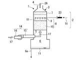
図1に示すように、空気浄化装置1は、空気浄化装置本体2と送風装置14により構成されている。前記空気浄化装置本体2は、一般に用いられているものと同様の筒型の塔形状の外殻3を有しており、その上方には浄化された浄化空気26が排出される開口部4が設けられている。また、外殻3には、最も上方に第1のデミスタ7が、内方を塞ぐように配置されているとともに、その下方に第1の散水ノズル9、第1の充填材10を備えた主洗浄部8が配置され、該第1の充填材10より下方の側面には、前記送風装置14と連結する送風口5が設けられている。
前記第1のデミスタ7は、一般に微細な液滴の発生を伴う処理ガス中の液滴を除去する部材として用いられているもので、例えばステンレス繊維やガラス繊維等を網目状に重ねる、またはポリプロピレン繊維等をろ布状に織る等の加工を施すことにより成形されるものである。また、前記第1の散水ノズル9は、排気ガス17中に含まれる汚染物質を吸収する液剤11を、前記外殻3の内方に散水するもので、散水される液剤11は、排気ガス17に含まれる汚染物質の種類に応じて、水、アルカリ性液剤、酸性液剤等が用いられている。これらの液剤11は、第1の散水ノズル9に直結された供給配管23により供給され、本実施の形態において、第1の散水ノズル9では、液剤11を循環させることなく、供給配管23により供給された液剤11のみを散水する構成としている。
【0013】
また、前記第1の充填材10は、前記液剤11と排気ガス17との接触効率を向上することを目的に用いられるもので、所定の層厚を持って外殻3の内方を塞ぐように配置されている。該第1の充填材10は、上方に配された前記散水ノズル9より散水された粒径状の液剤11が、表面に付着しやすいよう表面積が大きく形成されており、一般には酸、アルカリ、有機ガスに対して耐久性のある無機質多壁面体、又はポリプロピレン布等を多壁面体に加工したもの等が用いられている。なお、第1の充填材10に用いられる材料は、これらにこだわるものではなく、大きい表面積を形成でき、酸、アルカリ、有機ガスに触れても分解したり脆弱になることのない耐久性の高い材料であればいずれを用いても良い。
【0014】
本実施の形態では、第1の充填材10に対して高い親水性を持たせることを目的に、親水性のポリエステル布、ポリプロピレン布を表面材とし、板状に成形されたステンレスメッシュ、またはポリプロピレンメッシュを担持体として、担持体に表面材を接着、融着、縫製などにより一体化した親水板材10aを用いている。該親水板材10aの形状は、当然のことながら担持体に依存するため、担持体の外形状を加工した上で複数を組み合わせることにより、高い親水性を持ち、表面積の大きい第1の充填材10を成形することができるものである。これら親水板材10aを用いた第1の充填材10の事例を以下に示す。
【0015】
図4(a)に示す第1の充填材10は、波形に加工した隣り合う前記親水板材10a、10bを複数平行に配置し、凸面どうしを接触させて無機系もしくは水ガラス系接着剤等を用いて固着したものである。また、図4(b)に示す第1の充填材10は、複数の前記親水板材10aを互いに直交するように組み合わせて無機系接着剤を用いて固着しており、平面視格子状に成形したものである。さらに、図4(c)に示す第1の充填材10は、前記親水板材10aを所定の距離を持って平行に配置し、この配置を維持するように所定の容器24に収めたものである。
なお、これら第1の充填材10は、いずれも親水板材10aの板面が垂直面を形成するように配置されているが、必ずしもこれにこだわるものではなく、親水板材10aの板面に接触した液剤11が、重力により下方へ流下できる程度の傾斜を有していれば、水平面に対していずれの角度を有して成形されても良い。
また、図4(a)に示す隣り合う前記親水板材10a、10bは、両者が異なる角度で接合されていても良い。
【0016】
これらは、いずれも高い親水性を有するだけでなく表面積も大きく、例えば図4(a)に示す第1の充填材10では、充填材1m3に対して表面積が約500m2/m3を有する大きさに成形されている。この広大な表面積に液剤11が接触して水膜を形成することにより、水膜に排気ガス17が向流接触して汚染物質を効率よく吸収することができるものである。したがって、第1の充填材10は、その層厚を低く設定しても、十分な表面積が得られるため、第1の充填材10を湿潤させることを目的に大量の液剤11を用いる必要がなく、従来と比較しても大幅に少ない0.01〜1L/m3程度の液ガス比で十分な汚染物質の吸収が行えるものである。
このような第1の充填材10に付着された液剤11は、排気ガス17に含まれる汚染物質を吸収した後、重力に従い前記親水板材10aの板面流下し、外殻3の底部に設けられた液槽6に一次貯留され、排水口6aより排水されて、図示しない有機排水処理槽で処理されることとなる。
【0017】
一方、前記外殻3の下方に設けられた送風口5には、前記送風装置14が連結されている。該送風装置14は、外殻3の送風口5に一方の端部が固着され、外殻3と連通する送風管15と、該送風管15の他方の端部に取り付けられる送風機16とにより構成される。このような送風装置14は、送風機16により排気ガス17を取り込み送風管15を介して、空気浄化装置本体2の内方に排気ガス17を送入するもので、送風管15が水平に配されていることから、排気ガス17は、水平流として空気浄化装置本体2の内方へ送入されるものである。
【0018】
このような構成の空気浄化装置1を用いた排気ガス17の浄化手順を以下に示す。工場等で排出された排気ガス17は、前記送風装置4の送風機16を用いて送風管15に取り込まれる。該送風管15内で排気ガス17は水平流となり、空気浄化装置本体2を構成する外殻3の下方に設けられた送風口5より、外殻3の内方へ送入される。
該外殻3の内方へ送入された排気ガス17は上昇し、前記第1の充填材10を通過するが、該第1の充填材10には、第1の散水ノズル9より散水された粒径状の液剤11が付着して表面に水膜が形成されている。第1の充填材10を通過する排気ガス17はこの水膜に効率よく気液接触し、排気ガス17中の汚染物質が水膜を形成している液剤11に移行する。
さらに第1の充填材10を通過し上昇した排気ガス17は、再度第1の散水ノズル9より散水された粒径状の液剤11に直に気液接触し、排気ガス17中に残留する汚染物質が移行し、排気ガス17は浄化される。
これらの工程を経て浄化された浄化空気26は、液剤11による液滴を第1のデミスタ7に捕集された上で、外殻3の上方に設けられた開口部4より外方へ排出される。したがって、第1の充填材10より散水される液剤11は、常に有機物濃度が0mg/kgのものが用いられることとなる。
【0019】
(第2の実施の形態)
第1の実施の形態では、排気ガス17の汚染物質を除去するに際し、多量の液剤11を必要とせず、供給配管23による液剤11の供給量のみで十分な液ガス比が得られる場合に用いられる空気浄化装置1を示した。
第2の実施の形態では、前記排気ガス17中の汚染物質が、液剤11に溶解しやすい物質であるものの、第1の充填材10の層厚が大きく、第1の充填材10を湿潤させるために液剤11の供給量を増加させる必要がある場合の空気浄化装置1を以下に示す。
【0020】
図2に示すように、空気浄化装置1は、第1の実施の形態と同様の空気浄化装置本体2と送風装置14により構成されている。なお、本実施の形態では、空気浄化装置本体2の外殻3に、前記外殻3の底部に設けられた液槽6と前記第1の散水ノズル9とを連結する連結ポンプ18が設けられている。
したがって、第1の散水ノズル9には、供給配管23より給水される液剤11のみでなく、すでに第1の散水ノズル9より散水されて液槽6に貯留された貯留液剤12が相まった調整液剤13が、連結ポンプ18により循環供給される構成となっている。これにより、調整液剤13は、貯留液剤12を含むことから前記液槽6を十分な体積に確保しておくことにより、大量の液ガス比にも対応することが可能であり、第1の充填材10の層厚が大きい場合にも、十分な供給量を確保することができるものである。
【0021】
なお、所定量以上の汚染物質が含有した貯留液剤12は、循環使用されることなく、前記液槽6に設けられた排水口6aより排水され、図示しない有機排水処理装槽で処理される。また、前記液槽6には補給口6bが設けられており、該補給口6bより、新たな液剤11が供給されて、貯留液剤12の有機物濃度が調整されることとなる。したがって、前記液槽6に、液槽6中の貯留液剤12に係る図示しない有機物濃度の制御装置を取り付けておき、貯留液剤12の排水や新たな液剤11の供給を自動化させる構成としても良い。
【0022】
(第3の実施の形態)
第3の実施の形態では、排気ガス17中に、除去対象となる汚染物質以外の粉塵やミストなどの固体及び粘着質の液体が含まれている場合や、排気ガス17中の汚染物質濃度が高い場合に用いられる空気浄化装置1を示す。
【0023】
図3に示すように、空気浄化装置1は、空気浄化装置本体2と送風装置14により構成され、送風装置14は第1の実施の形態及び第2の実施の形態と同様の構成を有している。また、空気浄化装置本体2も第1の実施の形態及び第2の実施の形態と同様に、塔形状の外殻3を有しており、上方に開口部4、底部に液槽6、及び下部側面に送風口5を備え、その内方には上方に第1のデミスタ7、その下方に主洗浄部8を備えている。
第3の実施の形態では、前記主洗浄部8を構成する第1の充填材10の下方に、中間ドレン層25が配置されており、貯留液剤12が貯留されている。該中間ドレン層25と第1の散水ノズル9とは、連結ポンプ18により連結されており、第1の散水ノズル9は、給水配管23より供給される液剤11に加えて、中間ドレン層に貯留される貯留液剤12を循環供給され、液剤11と貯留液剤12が相まった調整液剤13を第1の充填材10に散水し、第1の充填材10を流下した調整液剤13は、貯留液剤12となって中間ドレン層25に貯留される。
【0024】
該中間ドレン層25の下方で送風口5より上方の高さ位置には、下方から上方の順に、第2のデミスタ22、第2の充填材21、第2の散水ノズル20を備えた前処理部19が配置されている。前記第2のデミスタ22及び第2の充填材21は各々、第1の実施の形態で述べた第1のデミスタ7及び第1の充填材10と同様の材料により構成されており、前記外殻3の内方を塞ぐように各々が配置されている。
また、前記第2の充填材21の上方に配されている第2の散水ノズル20は、連結ポンプ18を介して外殻3の底部に設けられている液槽6に連結されており、該液槽6に貯留されている貯留液剤12を循環利用して第2の充填材21に散布するものである。
【0025】
これら第3の実施の形態では、排気ガス17の浄化作業が前処理部19及び主洗浄部8の2段階で実施される構成となっており、前処理部19では、第2の散水ノズル20より液槽6に貯留されている貯留液剤12を循環利用し、主洗浄部8では、第1の散水ノズル9より液剤11と貯留液剤12が相まった調整液剤13が散水される。したがって、空気浄化装置本体2の上層に位置する主洗浄部8で用いられる調整液剤13と比較して、下層に位置する前処理部19では、排気ガス17の汚染物質の吸着に、有機物濃度の高い貯留液剤12が用いられる構成となっている。
【0026】
このような構成の空気浄化装置1を用いた排気ガス17の浄化手順を以下に示す。工場等で排出された排気ガス17は、前記送風装置4の送風機16を用いて送風管15に取り込まれる。該送風管15内で排気ガス17は、水平流として送風管15内を通過し、空気浄化装置本体2を構成する外殻3の下方に設けられた送風口5より、外殻3の内方へ送入される。
該外殻3の内方へ送入された排気ガス17は上昇し、前記前処理部19に送風される。前記前処理部19では、まず、第2のデミスタ22を通過することにより、汚染物質以外の粉塵やミストなどの固体、及び粘着質の液体等を除去される。この後、前記第2の充填材21を通過するが、該第2の充填材21には第2の散水ノズル20より散水された粒径状の貯留液剤12が付着して水膜を形成しており、この水膜に向流接触し効率よく気液接触されて排気ガス17中の汚染物質が貯留液剤12に移行する。さらに、第2の充填材21を通過し上昇する排気ガス17は、再度第2の散水ノズル9より散水された粒径状の液剤11に直に気液接触し、排気ガス17に残留する汚染物質が液剤11に移行する。
【0027】
該前処理部19を通過した排気ガス17は、次に、前記主洗浄部8に送風される。該主洗浄部8では、第1の充填材10を通過する。このとき、第1の散水ノズル9より散水された粒径状の調整液剤13が、第1の充填材10に付着して水膜を形成しており、これらに向流接触し効率よく気液接触されて排気ガス17中の汚染物質が調整液剤13に移行し、排気ガス17は浄化される。
さらに、第1の充填材10を通過し上昇した排気ガス17は、再度第1の散水ノズル9より散水された粒径状の調整液剤13に直に気液接触し、排気ガス17に残留する汚染物質が調整液剤13に移行し、排気ガス17は浄化される。これらの工程を経て浄化された浄化空気26は、第1のデミスタ7を通過して液滴を捕集された後に、外殻3の上端部に設けられた開口部4より外方へ排出される。
【0028】
なお、前記第2のデミスタ22は、捕集した汚染物質以外の粉塵やミストなどの固体、及び粘着質の液体等が付着しても上方に備えられた第2の散水ノズル20より散水された粒径状の貯留液剤12により洗い流されることとなるため、特別なメンテナンスは必要とならない。
また、第2の実施の形態と同様に、前記液槽6における所定定量以上の汚染物質が含有した貯留液剤12は、循環使用されることなく、排水口6aより排水され、図示しない有機排水処理装槽で処理される。また、前記液槽6には補給口6bが設けられており、該補給口6bより、新たな液剤11が供給されて、貯留液剤12の有機物濃度が調整されることとなる。
【0029】
このように、第1及び第2の実施の形態に示した空気浄化装置1はいずれも、空気浄化装置本体2の上方から下方に進むに従い、液剤11もしくは調整液剤13中に含まれる有機物濃度が増加する。また、第3の実施の形態においても、空気浄化装置本体2の上方に配置された主洗浄部8で用いられる調整液剤13と、下方に配置された前処理部19で用いられる貯留液剤12では、貯留液剤12の方が有機物濃度が高い。一方で、空気浄化装置本体2の下方から送風された排気ガス17は、汚染物質を浄化されながら上方に進むため、汚染物質濃度も上方から下方に進むに従い徐々に低下することとなる。
【0030】
一般に、有機物濃度の低い液剤11は、汚染物質濃度の低い排気ガス17中に含まれる汚染物質を吸収しやすく、有機物濃度の高い液剤11は、汚染物質濃度の高い排気ガス17中の汚染物質を吸収しやすいことが、一般に知られている。したがって、本実施の形態における空気浄化装置1は、空気浄化装置本体2の上層において、汚染物質濃度が既に低下した排気ガス17を、汚染物質をほぼ吸収していない液剤11、もしくは液剤11と貯留液剤12が相まった調整液剤13に直接気液接触させ、下層において汚染物質濃度の高い排気ガス17を、すでに汚染物質を含んだ有機物濃度の高い調整液剤13、又は貯留液剤12に気液接触させることから、排気ガス17の汚染物質濃度に準じて効率的に汚染物質を除去することができるものである。
【0031】
これらの効果を把握すべく、第1の実施の形態で示した空気浄化装置本体2の内方に、前処理部19を配置することなく主洗浄部8のみを配置した空気浄化装置1について、前記排気ガス17の流入風速を1.5m/s、空気浄化装置本体2に備えられた充填材10の部材厚を0.2m、液剤11の液ガス比を0.11L/m3 として設定した場合を例に取り、排気ガス17中の汚染物質の除去率を算定した。なお、排気ガス17中の汚染物質には、プロピレングリコールモノメチルエーテルやプロピレングリコールモノメチルエーテルアセテート、乳酸エチル等が含まれていることを想定している。
その結果、空気浄化装置1は排気ガス17の汚染物質を66〜71%程度まで除去することが可能となった。また、前記排気ガス17の流入風速を1.5m/s、空気浄化装置本体2に備えられた充填材10の部材厚を0.3m、液剤11の液ガス比を0.26L/m3 として設定した場合を例に取り、排気ガス17の汚染物質の除去率を算定した。その結果、空気浄化装置1は排気ガス17の汚染物質を72〜80%程度まで除去することが可能となった。
【0032】
一方で、従来より用いられている図5に示すような空気浄化装置27について、充填材37の層厚が2m、汚染物質の吸収に用いる液剤39は循環利用、また送風装置35より空気浄化装置本体28内に排気ガス38を送風する風速を1.5m/sと設定し、排気ガス38の除去を行うと、排気ガス38中の汚染物質の除去率は、液剤39中の有機物濃度が0mg/kgの場合には78%程度であることから、第1の充填材の層厚が1/6程度、液ガス比が1/15程度となっても、従来の空気浄化装置27と同程度の除去率を達成できることがわかる。
【0033】
【発明の効果】
請求項1記載の空気浄化装置によれば、排気ガス中の汚染物質を液剤に吸収させて、排気ガスを浄化する空気浄化装置本体と、該空気浄化装置本体の側面下部に連結されて、空気浄化装置本体の内方に排気ガスを送入する送風装置を備える空気浄化装置であって、空気浄化装置本体が、上方に開口部、下部側面に前記送風装置と連通する送風口、及び底部に前記液剤が貯留する液槽が備えられる筒型の外郭と、該外郭の送風口より上方で内方を水平に塞ぐようにして配置される第1の充填材、及び該第1の充填材の上方に配され、前記液剤を第1の充填材に散水する第1の散水ノズルにより構成される主洗浄部と、該主洗浄部の上方で外郭の内方を水平に塞ぐようにして配され、排気ガス中の液滴を除去する第1のデミスタにより構成され、前記主洗浄部の第1の充填材が、板状に成形され表面に水膜を形成する親水性の親水板材を、板面が水平より傾斜を有するように複数組み合わせて形成された多壁面体により構成されるとともに、前記第1の散水ノズルが、液剤を供給する供給配管に直結されていることから、充填材における1m3あたりの表面積が大幅に増加するため、層厚を小さく形成でき、従来と同程度の汚染物質の除去率を確保しながら、空気浄化装置全体をコンパクト化できるとともに、イニシャルコストを大幅に低減することが可能となる。また、充填材の層厚を小さく形成できるため、液剤の供給量も大幅に削減でき、液剤を循環する場合にも大型の連結ポンプを用いる必要がなく、ランニングコストを削減することが可能となる。
【0034】
請求項2記載の空気浄化装置によれば、前記第1の散水ノズルに、前記液槽と連結する連結ポンプが備えられており、前記第1の散水ノズルが、前記供給配管より供給される液剤に加えて、前記連結ポンプより供給される液槽中の貯留液剤を、前記第1の充填材に散水することから、第1の充填材の層厚を大きく設定し、大量の液剤が必要な場合にも、容易に対応することが可能となる。
【0035】
請求項3記載の空気浄化装置によれば、前記外殻の内方で主洗浄部の下方に、第1の散水ノズルより散水される液剤を貯留する中間ドレン槽が設けられるとともに、該中間ドレン槽と送風口との間の高さ位置に、下方から上方の順で前記外殻の内方を塞ぐように配置される第2のデミスタ、第2の充填材、及び第2の散水ノズルを備える前処理部が設けられ、前記第1の散水ノズルに、前記中間ドレン槽と連結する連結ポンプが備えられて、前記第1の散水ノズルが、前記供給配管より供給される液剤に加えて、前記連結ポンプより供給される中間ドレン槽中の貯留液剤を、前記第1の充填材に散水するとともに、前記第2の散水ノズルに、前記液槽と連結する連結ポンプが備えられて、前記第2の散水ノズルが、連結ポンプより供給される液槽中の貯留液剤を、前記第2の充填材に散水することから、排気ガスに粉塵やミストなどの固体、粘着質の液体が含まれている場合にも前処理部の第2のデミスタで捕集することができるとともに、除去対象となる汚染物質濃度が高い場合にも、主洗浄部と前処理部の2段階で汚染物質の除去作業が行われるため、従来の空気浄化装置と同程度の除去率を達成することが可能となる。
【図面の簡単な説明】
【図1】本発明の空気浄化装置の第1の実施の形態を示す図である。
【図2】本発明の空気浄化装置の第2の実施の形態を示す図である。
【図3】本発明の空気浄化装置の第3の実施の形態を示す図である。
【図4】本発明の空気浄化装置の第1の充填材を示す図である。
【図5】従来の空気浄化装置を示す図である。
【符号の説明】
1 空気浄化装置
2 空気浄化装置本体
3 外殻
4 開口部
5 送風口
6 液槽
6a 排水口
7 第1のデミスタ
8 主洗浄部
9 第1の散水ノズル
10 第1の充填材
10a 親水板材
10b 親水板材
11 液剤
12 貯留液剤
13 調整液剤
14 送風装置
15 送風管
16 送風機
17 排気ガス
18 連結連結ポンプ
19 前処理部
20 第2の散水ノズル
21 第2の充填材
22 第2のデミスタ
23 供給配管
24 容器
25 中間ドレン層
26 浄化空気
27 空気浄化装置
28 空気浄化装置本体
29 連結ポンプ
30 補給口
31 外殻
32 開口部
33 液槽
34 送風口
35 送風装置
36 散水ノズル
37 充填材
38 排気ガス
39 液剤
40 デミスタ[0001]
TECHNICAL FIELD OF THE INVENTION
The present invention relates to an air purification device that purifies pollutants in exhaust gas.
[0002]
[Prior art]
BACKGROUND ART Conventionally, an air purifying device generally called a vertical scrubber has been used for purifying pollutants such as water-soluble organic gas, acid and alkali substances contained in exhaust gas discharged from factories and the like. (See, for example, Non-Patent Document 1). As shown in FIG. 5, the air purifying
An
[0003]
When the
The
[0004]
[Non-patent document 1]
Edited by The Japan Society for Chemical Engineering, Technology for Preventing Odor and Hydrocarbon Emissions, Giyo Shoin Co., Ltd.
[0005]
[Problems to be solved by the invention]
It is assumed that the pollutants contained in the
For this reason, in order to maintain the removal rate of contaminants by the
[0006]
Further, when removing contaminants in the
[0007]
In view of the above circumstances, an object of the present invention is to provide an air purifying apparatus that efficiently purifies pollutants in exhaust gas with a simple configuration.
[0008]
[Means for Solving the Problems]
The air purification device according to
[0009]
3. The air purifying apparatus according to
[0010]
In the air purifying apparatus according to
[0011]
BEST MODE FOR CARRYING OUT THE INVENTION
Hereinafter, an air purification device of the present invention is shown in FIG. The present invention is directed to an air purification system that forms a water film on a wall surface by adhering a liquid agent to a filler made of a multi-wall body provided in an air purification device, and purifies by transferring pollutants in exhaust gas to the water film. In the device, by applying a multi-walled body having a small layer height but a large surface area and a high hydrophilicity to the filler, the amount of circulation of the liquid agent for purifying the exhaust gas is significantly reduced, and the exhaust gas is efficiently exhausted. Is performed.
[0012]
(First Embodiment)
As shown in FIG. 1, the
The
[0013]
The
[0014]
In the present embodiment, in order to impart high hydrophilicity to the
[0015]
The
Although the
The adjacent
[0016]
Each of them has not only high hydrophilicity but also a large surface area. For example, in the
After absorbing the contaminants contained in the
[0017]
On the other hand, the
[0018]
A procedure for purifying the
The
Further, the
The purified
[0019]
(Second embodiment)
The first embodiment is used in a case where a sufficient liquid-gas ratio can be obtained only by the supply amount of the
In the second embodiment, the contaminant in the
[0020]
As shown in FIG. 2, the
Therefore, not only the
[0021]
The stored
[0022]
(Third embodiment)
In the third embodiment, when the
[0023]
As illustrated in FIG. 3, the
In the third embodiment, an
[0024]
A pretreatment including a
In addition, a
[0025]
In the third embodiment, the purifying operation of the
[0026]
A procedure for purifying the
The
[0027]
The
Further, the
[0028]
The
In the same manner as in the second embodiment, the stored
[0029]
As described above, in each of the
[0030]
In general, the
[0031]
In order to grasp these effects, regarding the
As a result, the
[0032]
On the other hand, in the conventional
[0033]
【The invention's effect】
According to the air purifying apparatus of the first aspect, the air purifying apparatus main body for purifying the exhaust gas by absorbing the pollutants in the exhaust gas into the liquid agent and the lower part of the side surface of the air purifying apparatus body, An air purifying device including a blower for feeding exhaust gas into a purifier main body, wherein the air purifier main body has an opening at an upper portion, a blower opening communicating with the blower at a lower side surface, and a bottom portion. A cylindrical outer shell provided with a liquid tank in which the liquid agent is stored, a first filler disposed so as to horizontally close an inner side above a blowing port of the outer shell, and a first filler. A main cleaning unit including a first watering nozzle that is disposed above and sprays the liquid agent on the first filler, and is disposed so as to horizontally close an inner portion of the outer shell above the main cleaning unit. , A first demister for removing droplets in the exhaust gas, A multi-walled body formed by combining a plurality of hydrophilic plate materials in which the first filler of the main cleaning unit is formed into a plate shape and forms a water film on the surface so that the plate surface is inclined more than horizontal. And the first sprinkling nozzle is directly connected to the supply pipe for supplying the liquid agent, so that 1 m 3 As the surface area per unit area increases significantly, the thickness of the layer can be reduced, and the air purifier can be made more compact and the initial cost can be significantly reduced, while maintaining the same level of contaminant removal rates as before. Becomes possible. Further, since the layer thickness of the filler can be formed to be small, the supply amount of the liquid agent can be significantly reduced, and even when the liquid agent is circulated, it is not necessary to use a large connecting pump, and the running cost can be reduced. .
[0034]
According to the air purification device of
[0035]
According to the air purifying apparatus of the third aspect, an intermediate drain tank for storing a liquid agent sprayed from the first water spray nozzle is provided below the main washing section inside the outer shell and the intermediate drain tank. A second demister, a second filler, and a second watering nozzle which are arranged at a height position between the tank and the blower port so as to close the inside of the outer shell in order from below to above. A pretreatment unit is provided, and the first watering nozzle is provided with a connection pump connected to the intermediate drain tank, and the first watering nozzle is provided in addition to the liquid agent supplied from the supply pipe, A liquid pump in the intermediate drain tank supplied from the connection pump is sprinkled on the first filler, and the second watering nozzle is provided with a connection pump connected to the liquid tank. Two watering nozzles are supplied by the connecting pump Since the liquid stored in the tank is sprinkled on the second filler, the second demister of the pre-processing section can also use the second demister even when the exhaust gas contains a solid or sticky liquid such as dust or mist. In addition to being able to collect, even when the concentration of contaminants to be removed is high, the contaminant removal work is performed in two stages, the main cleaning section and the pretreatment section, so it is comparable to a conventional air purification device. Can be achieved.
[Brief description of the drawings]
FIG. 1 is a diagram showing a first embodiment of an air purification device of the present invention.
FIG. 2 is a view showing a second embodiment of the air purification device of the present invention.
FIG. 3 is a view showing a third embodiment of the air purification device of the present invention.
FIG. 4 is a diagram showing a first filler of the air purification device of the present invention.
FIG. 5 is a diagram showing a conventional air purification device.
[Explanation of symbols]
1 air purification device
2 Air purification device body
3 outer shell
4 opening
5 Blow port
6 liquid tank
6a drain
7 First demister
8 Main cleaning section
9 First watering nozzle
10 First filler
10a hydrophilic plate material
10b Hydrophilic plate material
11 liquids
12 Storage liquid agent
13 Adjusting liquid
14 Blower
15 Blower tube
16 Blower
17 Exhaust gas
18 Connecting pump
19 Pre-processing unit
20 Second watering nozzle
21 Second filler
22 Second demister
23 Supply piping
24 containers
25 Intermediate drain layer
26 Purified air
27 Air purification device
28 Air purification device body
29 Connecting pump
30 Supply port
31 outer shell
32 opening
33 liquid tank
34 Blow port
35 Blower
36 Watering nozzle
37 filler
38 Exhaust gas
39 solutions
40 demister
Claims (3)
該空気浄化装置本体の側面下部に連結されて、空気浄化装置本体の内方に排気ガスを送入する送風装置を備える空気浄化装置であって、
空気浄化装置本体が、上方に開口部、下部側面に前記送風装置と連通する送風口、及び底部に前記液剤が貯留する液槽が備えられる筒型の外郭と、
該外郭の送風口より上方で内方を水平に塞ぐようにして配置される第1の充填材、及び該第1の充填材の上方に配され、前記液剤を第1の充填材に散水する第1の散水ノズルにより構成される主洗浄部と、
該主洗浄部の上方で外郭の内方を水平に塞ぐようにして配され、排気ガス中の液滴を除去する第1のデミスタにより構成され、
前記主洗浄部の第1の充填材が、板状に成形され表面に水膜を形成する親水性の親水板材を、板面が水平より傾斜を有するように複数組み合わせて形成された多壁面体により構成されるとともに、
前記第1の散水ノズルが、液剤を供給する供給配管に直結されていることを特徴とする空気浄化装置。An air purification device body for purifying exhaust gas by absorbing contaminants in the exhaust gas into a liquid agent,
An air purification device including a blower that is connected to a lower portion of a side surface of the air purification device main body and that supplies exhaust gas to an inside of the air purification device main body,
The air purification device main body has an opening on the upper side, a blowing port communicating with the blowing device on a lower side surface, and a cylindrical outer shell provided with a liquid tank for storing the liquid agent at a bottom portion,
A first filler disposed so as to horizontally close the inside above the air outlet of the outer shell; and a first filler disposed above the first filler to spray the liquid agent on the first filler. A main cleaning unit configured by a first watering nozzle;
A first demister that is disposed so as to horizontally close the inside of the outer shell above the main cleaning unit and removes droplets in exhaust gas;
A multi-walled body formed by combining a plurality of hydrophilic plate materials in which the first filler of the main cleaning unit is formed into a plate shape and forms a water film on the surface so that the plate surface is inclined from horizontal. Is composed of
An air purifying device, wherein the first watering nozzle is directly connected to a supply pipe for supplying a liquid agent.
前記第1の散水ノズルに、前記液槽と連結する連結ポンプが備えられており、前記第1の散水ノズルが、前記供給配管より供給される液剤に加えて、前記連結ポンプより供給される液槽中の貯留液剤を、前記第1の充填材に散水することを特徴とする空気浄化装置。The air purification device according to claim 1,
The first watering nozzle is provided with a connection pump connected to the liquid tank, and the first watering nozzle is provided with a liquid supplied from the connection pump in addition to a liquid supplied from the supply pipe. An air purification device, wherein a liquid stored in a tank is sprinkled on the first filler.
前記外殻の内方で主洗浄部の下方に、第1の散水ノズルより散水される液剤を貯留する中間ドレン槽が設けられるとともに、
該中間ドレン槽と送風口との間の高さ位置に、下方から上方の順で前記外殻の内方を塞ぐように配置される第2のデミスタ、第2の充填材、及び第2の散水ノズルを備える前処理部が設けられ、
前記第1の散水ノズルに、前記中間ドレン槽と連結する連結ポンプが備えられて、前記第1の散水ノズルが、前記供給配管より供給される液剤に加えて、前記連結ポンプより供給される中間ドレン槽中の貯留液剤を、前記第1の充填材に散水するとともに、
前記第2の散水ノズルに、前記液槽と連結する連結ポンプが備えられて、前記第2の散水ノズルが、連結ポンプより供給される液槽中の貯留液剤を、前記第2の充填材に散水することを特徴とする空気浄化装置。The air purification device according to claim 1,
Inside the outer shell, below the main washing section, an intermediate drain tank for storing the liquid agent sprayed from the first watering nozzle is provided,
A second demister, a second filler, and a second filler arranged at a height position between the intermediate drain tank and the air outlet so as to close the inside of the outer shell in order from below to above. A pre-processing unit having a watering nozzle is provided,
The first watering nozzle is provided with a connection pump connected to the intermediate drain tank, and the first watering nozzle is connected to the intermediate pump supplied from the connection pump in addition to the liquid supplied from the supply pipe. Sprinkling the liquid stored in the drain tank on the first filler,
The second watering nozzle is provided with a connection pump connected to the liquid tank, and the second watering nozzle supplies the liquid stored in the liquid tank supplied from the connection pump to the second filler. An air purification device characterized by spraying water.
Priority Applications (1)
| Application Number | Priority Date | Filing Date | Title |
|---|---|---|---|
| JP2002371749A JP3870375B2 (en) | 2002-12-24 | 2002-12-24 | Air purification device |
Applications Claiming Priority (1)
| Application Number | Priority Date | Filing Date | Title |
|---|---|---|---|
| JP2002371749A JP3870375B2 (en) | 2002-12-24 | 2002-12-24 | Air purification device |
Publications (2)
| Publication Number | Publication Date |
|---|---|
| JP2004202306A true JP2004202306A (en) | 2004-07-22 |
| JP3870375B2 JP3870375B2 (en) | 2007-01-17 |
Family
ID=32810553
Family Applications (1)
| Application Number | Title | Priority Date | Filing Date |
|---|---|---|---|
| JP2002371749A Expired - Fee Related JP3870375B2 (en) | 2002-12-24 | 2002-12-24 | Air purification device |
Country Status (1)
| Country | Link |
|---|---|
| JP (1) | JP3870375B2 (en) |
Cited By (7)
| Publication number | Priority date | Publication date | Assignee | Title |
|---|---|---|---|---|
| JP2009066434A (en) * | 2008-11-28 | 2009-04-02 | Sanyo Electric Co Ltd | Floor-standing air disinfecting apparatus |
| KR100943537B1 (en) | 2008-05-27 | 2010-02-22 | 주식회사 애니텍 | An Air Cleaner with Function Capable of CO2 Removal |
| KR101064661B1 (en) | 2009-12-15 | 2011-09-15 | (주)써스텍 | Gas Scrubber Having Improved Protecting Function Of Outlet Pipe |
| CN107519755A (en) * | 2017-10-19 | 2017-12-29 | 张家港市艾尔环保工程有限公司 | Multi-functional washing absorption plant |
| CN108619846A (en) * | 2018-07-11 | 2018-10-09 | 安徽京仪自动化装备技术有限公司 | A kind of semiconductor waste gas cleaning equipment |
| CN110075640A (en) * | 2019-04-24 | 2019-08-02 | 天津安瑞梦科技有限公司 | A kind of equipment for the wet plume that removes smoke |
| CN107559991B (en) * | 2017-09-21 | 2020-11-06 | 泗县飞虹体育文化发展有限公司 | Environment-friendly air purification equipment with adsorption liquid sprays function |
Families Citing this family (1)
| Publication number | Priority date | Publication date | Assignee | Title |
|---|---|---|---|---|
| KR102510015B1 (en) * | 2021-08-23 | 2023-03-14 | 최용준 | Hazardous particle emission reduction device using hydrophilic properties |
-
2002
- 2002-12-24 JP JP2002371749A patent/JP3870375B2/en not_active Expired - Fee Related
Cited By (7)
| Publication number | Priority date | Publication date | Assignee | Title |
|---|---|---|---|---|
| KR100943537B1 (en) | 2008-05-27 | 2010-02-22 | 주식회사 애니텍 | An Air Cleaner with Function Capable of CO2 Removal |
| JP2009066434A (en) * | 2008-11-28 | 2009-04-02 | Sanyo Electric Co Ltd | Floor-standing air disinfecting apparatus |
| KR101064661B1 (en) | 2009-12-15 | 2011-09-15 | (주)써스텍 | Gas Scrubber Having Improved Protecting Function Of Outlet Pipe |
| CN107559991B (en) * | 2017-09-21 | 2020-11-06 | 泗县飞虹体育文化发展有限公司 | Environment-friendly air purification equipment with adsorption liquid sprays function |
| CN107519755A (en) * | 2017-10-19 | 2017-12-29 | 张家港市艾尔环保工程有限公司 | Multi-functional washing absorption plant |
| CN108619846A (en) * | 2018-07-11 | 2018-10-09 | 安徽京仪自动化装备技术有限公司 | A kind of semiconductor waste gas cleaning equipment |
| CN110075640A (en) * | 2019-04-24 | 2019-08-02 | 天津安瑞梦科技有限公司 | A kind of equipment for the wet plume that removes smoke |
Also Published As
| Publication number | Publication date |
|---|---|
| JP3870375B2 (en) | 2007-01-17 |
Similar Documents
| Publication | Publication Date | Title |
|---|---|---|
| US5512072A (en) | Flue gas scrubbing apparatus | |
| KR950012520B1 (en) | Method and apparatus for the treatment of a waste gas containing dusts and chemical contaminants | |
| RU2038130C1 (en) | Method and equipment for cleaning waste gases | |
| PL183592B1 (en) | Scrubbing apparatus for flue gases | |
| KR100652969B1 (en) | Scrubber having diffraction plate with ultrasonic wave generator | |
| US4957519A (en) | Air-cleaning apparatus | |
| JP4145701B2 (en) | Air purification device | |
| CN111530205B (en) | Adsorption purification device for industrial oily waste gas treatment | |
| JP2015073990A (en) | Method and apparatus for wet desulfurization spray towers | |
| JP2006289155A (en) | Coating facility | |
| JP2001523563A (en) | Gas-liquid contactor with liquid redistribution device | |
| KR101055592B1 (en) | Water wall rotation type wet scrubber | |
| US20060185517A1 (en) | Multi-stage odor scrubber | |
| MXPA06008560A (en) | Paint spray booth. | |
| CN202113737U (en) | Washing tower | |
| JP2004202306A (en) | Air cleaner | |
| KR100638517B1 (en) | Scrubber having diffraction plate | |
| CN106422649A (en) | Integrated laboratory mixed waste gas purification device and purification method | |
| CN209406036U (en) | Organic waste-gas purification spray column | |
| CN209049172U (en) | A kind of industrial waste gas processing system | |
| JP2006175336A (en) | Wet gas purifier | |
| CN205627447U (en) | Atomizing scrubbing tower | |
| JP2004261781A (en) | Method and apparatus for treating exhaust gas | |
| CN209952474U (en) | Liquid washing air purifier | |
| JP7418045B2 (en) | Deodorizing equipment and method |
Legal Events
| Date | Code | Title | Description |
|---|---|---|---|
| A621 | Written request for application examination |
Free format text: JAPANESE INTERMEDIATE CODE: A621 Effective date: 20050125 |
|
| A977 | Report on retrieval |
Free format text: JAPANESE INTERMEDIATE CODE: A971007 Effective date: 20060227 |
|
| A131 | Notification of reasons for refusal |
Free format text: JAPANESE INTERMEDIATE CODE: A131 Effective date: 20060307 |
|
| A521 | Written amendment |
Free format text: JAPANESE INTERMEDIATE CODE: A523 Effective date: 20060425 |
|
| TRDD | Decision of grant or rejection written | ||
| A01 | Written decision to grant a patent or to grant a registration (utility model) |
Free format text: JAPANESE INTERMEDIATE CODE: A01 Effective date: 20060912 |
|
| A61 | First payment of annual fees (during grant procedure) |
Free format text: JAPANESE INTERMEDIATE CODE: A61 Effective date: 20061005 |
|
| R150 | Certificate of patent (=grant) or registration of utility model |
Free format text: JAPANESE INTERMEDIATE CODE: R150 |
|
| FPAY | Renewal fee payment (prs date is renewal date of database) |
Free format text: PAYMENT UNTIL: 20121027 Year of fee payment: 6 |
|
| FPAY | Renewal fee payment (prs date is renewal date of database) |
Free format text: PAYMENT UNTIL: 20121027 Year of fee payment: 6 |
|
| FPAY | Renewal fee payment (prs date is renewal date of database) |
Free format text: PAYMENT UNTIL: 20131027 Year of fee payment: 7 |
|
| LAPS | Cancellation because of no payment of annual fees |