JP2004201905A - Handle grip apparatus for pachinko game machine - Google Patents
Handle grip apparatus for pachinko game machine Download PDFInfo
- Publication number
- JP2004201905A JP2004201905A JP2002374008A JP2002374008A JP2004201905A JP 2004201905 A JP2004201905 A JP 2004201905A JP 2002374008 A JP2002374008 A JP 2002374008A JP 2002374008 A JP2002374008 A JP 2002374008A JP 2004201905 A JP2004201905 A JP 2004201905A
- Authority
- JP
- Japan
- Prior art keywords
- handle lever
- gear
- handle
- damper
- shaft
- Prior art date
- Legal status (The legal status is an assumption and is not a legal conclusion. Google has not performed a legal analysis and makes no representation as to the accuracy of the status listed.)
- Pending
Links
Images

Abstract
Description
【0001】
【発明の属する技術分野】
本発明はパチンコ機において球を発射するために人為操作されるハンドルグリップ装置に関する。
【0002】
【従来の技術】
装置本体に設けられた軸を介して回転可能に設けられたハンドルレバー(特許文献1では「グリップリング」と称されている)を備えたハンドルグリップ装置において、軸をオイルコンパウンドで被覆することで、球を発射させる方向とは逆方向のハンドルレバーの回転を抑制し、球を発射させる方向にハンドルレバーを回転させた場合にその回転位置を軽微な保持力で維持できるようにしたものが知られている(例えば、特許文献1参照)。
【0003】
【特許文献1】
特開平9−10388号公報
【0004】
【発明が解決しようとする課題】
特許文献1では、軸をオイルコンパウンドで被覆しただけなので、耐久性や操作性にばらつきが生じる。
本発明は球を発射させる方向にハンドルレバーを回転させた場合にその回転位置を軽微な保持力で維持できて遊技者の負担を軽減できるとともに、耐久性や操作性にばらつきのないハンドルグリップ装置を提供するものである。
【0005】
【課題を解決するための手段】
本発明にあっては、装置本体に回転可能に取付けられたハンドルレバーを備えたパチンコ機のハンドルグリップ装置において、装置本体に流体ダンパー装置を取付け、流体ダンパー装置のダンパー軸とハンドルレバーと力伝達機構を介して回転可能に連結したので、ハンドルレバーの回転位置を軽微な保持力で維持できて遊技者の負担を軽減できるとともに、耐久性や操作性にばらつきのないハンドルグリップ装置が得られる。
また、力伝達機構がギヤ機構により形成されたものとしたので、ハンドルレバーの回転に伴って流体ダンパー装置を確実に作動させることができ、上記効果が確実に得られる。
また、ハンドルレバー側のギヤ機構がハンドルレバーの裏側の外周側内壁に形成されたギヤにより形成されたものとしたので、流体ダンパー装置の作動即応性に優れ、ハンドルレバーの回転が少ない場合においても本願の効果が確実に得られる。
【0006】
【発明の実施の形態】
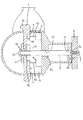
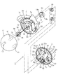
図1は実施形態によるパチンコ機のハンドルグリップ装置の断面図、図2はハンドルグリップ装置の分解斜視図、図3はハンドルレバーに対するロータリーダンパーと可変抵抗器の位置関係を示す分解斜視図である。
ハンドルグリップ装置1はグリップ本体2(装置本体)、ハンドルレバー3、カバー4に大別される。グリップ本体2のシャフト支持孔20にはシャフト5が嵌合され、シャフト5の一端5aがパチンコ機に設けられた取付けベース6に止ねじ7で取付けられる。グリップ本体2の部品収納部21には複数のカバー取付支柱22が設けられ、またロータリーダンパー8(流体ダンパー装置)が取付フランジ81を介して図外の止めねじで取付けられている。さらに図外の止ねじで部品取付ベース23がベース取付支柱24に固定され、この部品取付ベース23には可変抵抗器9が取付フランジ91を介して図外の止めねじで取付けられている。ロータリーダンパー8のダンパー軸82の先端83は異形に形成され、この異形先端83が歯車10の異形孔11に嵌め込まれることによってダンパー軸82の先端83に歯車10が取付けられている。また、可変抵抗器9のボリューム軸92の先端93は異形に形成され、この異形先端93が歯車12の異形孔13に嵌め込まれることによってボリューム軸92の先端93に歯車12が取付けられている。シャフト5の他端5b側には歯車14がシャフト挿通孔15を介して取付けられた後に、ハンドルレバー3がハンドルレバー3に形成された複数の逃孔30に複数のカバー取付支柱22を取り込みつつ、ハンドルレバー3がグリップ本体2の前側に被せられる。ハンドルレバー3の回転中心ベース部31に形成されたブッシュ挿通孔32にはブッシュ16が嵌め込まれ、このブッシュ16の軸受け孔17にシャフト5の他端5b側が挿入される。そして、ブッシュ16の径方向外側に突出したブラケット18とハンドルレバー3の回転中心ベース部31と歯車14とを接触させた状態で図外の止めねじをブッシュ16のブラケット18に形成された貫通孔19からハンドルレバー3の回転中心ベース部31に形成された貫通孔33を経由して歯車14のねじ孔14aに締結されることによって、歯車14がハンドルレバー3の回転中心ベース部31に固定的に取り付けられる。そして、ブッシュ16より突出するシャフト5の他端5bに止め輪50が取付けられる。それから、半球形のカバー4がハンドルレバー3の前側に被せられることによって、半球形のカバー4の後面より突出した複数の突起41とハンドルレバー3の逃孔30から前側に突出したカバー取付支柱22とが互いに突き合わされた後、図外の止ねじがグリップ本体2の裏面側からカバー取付支柱22の貫通孔22aを経由してカバー4の突起41に締結されることにより、カバー4がハンドルレバー3の回転操作を邪魔しないようにグリップ本体2に取り付けられる。このように組立られた状態において、可変抵抗器9のボリューム軸92に取付けられた歯車12は歯車14と噛み合い、また、ロータリーダンパー8のダンパー軸82に取付けられた歯車10はハンドルレバー3の裏側の外周側内壁60に形成されたギヤ61に噛み合う。このギヤ61は、歯車10に対するハンドルレバー3の回動範囲に合せて形成されている。可変抵抗器9のボリューム軸92に取付けられた歯車12と部品取付ベース23との間にはボリューム軸92を囲むスプリングコイル等の戻しばね70が設けられ、戻しばね70の一端71は歯車12に、他端72は部品取付ベース23に取付けられ、この戻しばね70によりハンドルレバー3に戻し方向の力が付与される。3aはハンドルレバー3の指掛部、90は可変抵抗器9の信号端子、94は信号線、95は信号線94を遊技機側に導くための孔である。尚、図1においては、カバー取付支柱22、部品取付ベース23、カバーの突起41、戻しばね70等の図示は省略している。
【0007】
図示はしないが、ロータリーダンパー8は、オイル等の粘性流体を封入するケーシングとこのケーシングから突出したダンパー軸82とこのダンパー軸82を一方向に回転させたときに回転負荷を軽くし回転軸を逆方向に回転させたときに回転負荷を重くする負荷調整装置とを備えるものである。負荷調整装置は、例えば、ダンパー軸82と連結されて粘性流体収納空間を区切る制御板により構成され、この制御板は逆止弁及びオリフィスを備え、ダンパー軸82が一方向に回転したときに逆止弁を介して粘性流体収納空間の間で流体移動させることで流体抵抗を少なくしてダンパー軸82の回転を軽くし、ダンパー軸82が逆方向に回転したときに逆止弁により粘性流体収納空間の間での流体の移動を規制、オリフィスを介してのみ流体を移動させことで流体抵抗を大きくしてダンパー軸82の回転負荷を重くするものである。
よって、球を発射させる方向とは逆方向にハンドルレバー3が回転する際にダンパー軸82の回転負荷が重くなるようにロータリーダンパー8を取付けておけばよい。
【0008】
実施形態によれば、球を発射させる方向にハンドルレバーを回転させた場合にその回転位置を軽微な保持力で維持できるので遊技者の負担を軽減できる。また、軽微な保持力でハンドル操作を安定させることができて球飛びを安定させることができる。また、オイル等の粘性流体をケーシングに封入したロータリーダンパー8を用いたので、耐久性や操作性にばらつきのないハンドルグリップ装置が得られる。
【0009】
また、ロータリーダンパー8のダンパー軸82に取付けられた歯車10を歯車14に噛み合わせてもよいが、この場合、ハンドルレバー3の回転に対するロータリーダンパー8のダンパー軸82の回転量が少なくなるので、ロータリーダンパー8の作動即応性に劣る。一方、上述したようにハンドルレバー3の裏側の外周側内壁60に形成されたギヤ61に対してダンパー軸82に取付けられた歯車10を噛み合わせれば、ハンドルレバー3の回転に対するロータリーダンパー8のダンパー軸82の回転量を稼げるので、ロータリーダンパー8の作動即応性に優れ、ハンドルレバー3の回転が少ない場合においても本願の効果が確実に得られる。
【0010】
尚、上記ではロータリーダンパー8のダンパー軸82とハンドルレバー3とを歯車10とギヤ61(あるいは歯車14)とのギヤ機構からなる力伝達機構を介して回転可能に連結した例を示したが、歯車14と歯車10とを歯車ベルトを介して連結してもよい。
【図面の簡単な説明】
【図1】本発明の実施形態のハンドルグリップ装置の断面図。
【図2】同実施形態のハンドルグリップ装置の分解斜視図。
【図3】同実施形態のハンドルレバーに対するロータリーダンパーと可変抵抗器の位置関係を示す分解斜視図。
【符号の説明】
1 ハンドルグリップ装置
2 グリップ本体(装置本体)
3 ハンドルレバー
8 ロータリーダンパー(流体ダンパー装置)
10 歯車(力伝達機構)
60 ハンドルレバーの裏側の外周側内壁
61 ギヤ(力伝達機構)
82 ダンパー軸[0001]
TECHNICAL FIELD OF THE INVENTION
The present invention relates to a handle grip device which is manually operated to fire a ball in a pachinko machine.
[0002]
[Prior art]
In a handle grip device provided with a handle lever (referred to as a "grip ring" in Patent Document 1) rotatably provided via a shaft provided in the device body, the shaft is covered with an oil compound. It is known that the rotation of the handle lever in the direction opposite to the direction in which the ball is fired is suppressed, and when the handle lever is rotated in the direction in which the ball is fired, the rotation position can be maintained with a slight holding force. (For example, see Patent Document 1).
[0003]
[Patent Document 1]
Japanese Patent Application Laid-Open No. 9-10388
[Problems to be solved by the invention]
In
The present invention provides a handle grip device that can maintain the rotation position with a small holding force when the handle lever is rotated in the direction in which the ball is fired, can reduce the burden on the player, and has no variation in durability and operability. Is provided.
[0005]
[Means for Solving the Problems]
According to the present invention, in a handle grip device of a pachinko machine having a handle lever rotatably attached to a device main body, a fluid damper device is attached to the device main body, and a force transmission between a damper shaft of the fluid damper device, the handle lever, and the power transmission device. Since it is rotatably connected via the mechanism, the rotation position of the handle lever can be maintained with a small holding force, so that the burden on the player can be reduced, and a handle grip device having no variation in durability and operability can be obtained.
In addition, since the force transmission mechanism is formed by a gear mechanism, the fluid damper device can be reliably operated with the rotation of the handle lever, and the above-described effects can be reliably obtained.
In addition, since the gear mechanism on the handle lever side is formed by a gear formed on the outer peripheral inner wall on the back side of the handle lever, the fluid damper device is excellent in operation responsiveness, even when the handle lever rotation is small. The effects of the present application can be reliably obtained.
[0006]
BEST MODE FOR CARRYING OUT THE INVENTION
1 is a sectional view of a handle grip device of a pachinko machine according to an embodiment, FIG. 2 is an exploded perspective view of the handle grip device, and FIG. 3 is an exploded perspective view showing a positional relationship between a rotary damper and a variable resistor with respect to a handle lever.
The
[0007]
Although not shown, the rotary damper 8 includes a casing for enclosing a viscous fluid such as oil, a
Therefore, the rotary damper 8 may be attached so that the rotation load of the
[0008]
According to the embodiment, when the handle lever is rotated in the direction in which the ball is fired, the rotational position can be maintained with a small holding force, so that the burden on the player can be reduced. In addition, the handle operation can be stabilized with a small holding force, and the ball jump can be stabilized. Further, since the rotary damper 8 in which the viscous fluid such as oil is sealed in the casing is used, a handle grip device having no variation in durability and operability can be obtained.
[0009]
Further, the
[0010]
In the above description, an example is shown in which the
[Brief description of the drawings]
FIG. 1 is a sectional view of a handle grip device according to an embodiment of the present invention.
FIG. 2 is an exploded perspective view of the handle grip device of the embodiment.
FIG. 3 is an exploded perspective view showing a positional relationship between a rotary damper and a variable resistor with respect to a handle lever of the embodiment.
[Explanation of symbols]
1 handle
3 Handle lever 8 Rotary damper (fluid damper device)
10 Gears (force transmission mechanism)
60 Outer peripheral
82 Damper shaft
Claims (3)
Priority Applications (1)
| Application Number | Priority Date | Filing Date | Title |
|---|---|---|---|
| JP2002374008A JP2004201905A (en) | 2002-12-25 | 2002-12-25 | Handle grip apparatus for pachinko game machine |
Applications Claiming Priority (1)
| Application Number | Priority Date | Filing Date | Title |
|---|---|---|---|
| JP2002374008A JP2004201905A (en) | 2002-12-25 | 2002-12-25 | Handle grip apparatus for pachinko game machine |
Publications (1)
| Publication Number | Publication Date |
|---|---|
| JP2004201905A true JP2004201905A (en) | 2004-07-22 |
Family
ID=32812153
Family Applications (1)
| Application Number | Title | Priority Date | Filing Date |
|---|---|---|---|
| JP2002374008A Pending JP2004201905A (en) | 2002-12-25 | 2002-12-25 | Handle grip apparatus for pachinko game machine |
Country Status (1)
| Country | Link |
|---|---|
| JP (1) | JP2004201905A (en) |
Cited By (4)
| Publication number | Priority date | Publication date | Assignee | Title |
|---|---|---|---|---|
| JP2006230949A (en) * | 2005-02-28 | 2006-09-07 | Sansei R & D:Kk | Pachinko game machine |
| JP2009268750A (en) * | 2008-05-08 | 2009-11-19 | Kyoraku Sangyo Kk | Accessory device of game machine |
| JP2011212055A (en) * | 2010-03-31 | 2011-10-27 | Kyoraku Sangyo Kk | Game machine |
| JP2011212053A (en) * | 2010-03-31 | 2011-10-27 | Kyoraku Sangyo Kk | Game machine |
-
2002
- 2002-12-25 JP JP2002374008A patent/JP2004201905A/en active Pending
Cited By (4)
| Publication number | Priority date | Publication date | Assignee | Title |
|---|---|---|---|---|
| JP2006230949A (en) * | 2005-02-28 | 2006-09-07 | Sansei R & D:Kk | Pachinko game machine |
| JP2009268750A (en) * | 2008-05-08 | 2009-11-19 | Kyoraku Sangyo Kk | Accessory device of game machine |
| JP2011212055A (en) * | 2010-03-31 | 2011-10-27 | Kyoraku Sangyo Kk | Game machine |
| JP2011212053A (en) * | 2010-03-31 | 2011-10-27 | Kyoraku Sangyo Kk | Game machine |
Similar Documents
| Publication | Publication Date | Title |
|---|---|---|
| JP4810200B2 (en) | Operation device for adjusting hitting force in gaming machines | |
| US20090198158A1 (en) | Massage device with spiral wave form action | |
| JP5647549B2 (en) | Bullet ball machine | |
| JP2004201905A (en) | Handle grip apparatus for pachinko game machine | |
| JP5508225B2 (en) | Launch operation device | |
| JP3579126B2 (en) | Pachinko machine handle device | |
| JP2009273761A (en) | Shooting handle for game machine and game machine equipped with the same | |
| JP4421217B2 (en) | Pachinko machine launch control device | |
| JP2005040426A (en) | Operating handle for pachinko machine | |
| US6000069A (en) | Compound torque hinge | |
| JP4789852B2 (en) | Launcher handle of bullet ball machine | |
| JPH048939Y2 (en) | ||
| JP5794524B2 (en) | Bullet ball machine | |
| US5991936A (en) | Opening and closing device of Western style toilet seat and seat cover | |
| JP5812427B2 (en) | Game machine | |
| JP4451702B2 (en) | Pachinko machine launch operation mechanism | |
| JP2005160504A (en) | Hitting operation mechanism of game machine | |
| JP2006158786A (en) | Shooting operation device for pachinko game machine | |
| JP3579871B2 (en) | Handle grip structure of pachinko machine | |
| JP5314254B2 (en) | Launcher handle of bullet ball machine | |
| JP2001017627A (en) | Operation handle for game machine | |
| JP2005027882A (en) | Shooting operation device for pachinko game machine | |
| JP5358352B2 (en) | Handle device for gaming machine | |
| JP4382400B2 (en) | Pachinko machine launch control device | |
| JP2007283031A (en) | Shootor of game machine |
Legal Events
| Date | Code | Title | Description |
|---|---|---|---|
| A621 | Written request for application examination |
Effective date: 20050927 Free format text: JAPANESE INTERMEDIATE CODE: A621 |
|
| A131 | Notification of reasons for refusal |
Effective date: 20090106 Free format text: JAPANESE INTERMEDIATE CODE: A131 |
|
| A977 | Report on retrieval |
Free format text: JAPANESE INTERMEDIATE CODE: A971007 Effective date: 20090107 |
|
| A02 | Decision of refusal |
Free format text: JAPANESE INTERMEDIATE CODE: A02 Effective date: 20090512 |