JP2004201231A - Monitoring video camera system - Google Patents
Monitoring video camera system Download PDFInfo
- Publication number
- JP2004201231A JP2004201231A JP2002370436A JP2002370436A JP2004201231A JP 2004201231 A JP2004201231 A JP 2004201231A JP 2002370436 A JP2002370436 A JP 2002370436A JP 2002370436 A JP2002370436 A JP 2002370436A JP 2004201231 A JP2004201231 A JP 2004201231A
- Authority
- JP
- Japan
- Prior art keywords
- video
- video data
- camera
- surveillance
- surveillance camera
- Prior art date
- Legal status (The legal status is an assumption and is not a legal conclusion. Google has not performed a legal analysis and makes no representation as to the accuracy of the status listed.)
- Withdrawn
Links
Images


Abstract
Description
【0001】
【発明の属する技術分野】
本発明は、防犯,防災,安全監視などに用いられ、特に広視野な全体映像と、この全体映像中で動きのある部分を拡大した部分ズーム映像とを同時に撮影可能な監視用ビデオカメラシステムに関するものである。
【0002】
【従来の技術】
従来の監視カメラは、監視対象となる領域に向けて固定設置されて、監視対象領域を常時監視しているものが一般的であるが、より広範囲の領域を撮影する必要がある場合には、複数台の監視カメラを監視対象となる領域の各方向に固定配置する方法や、一台の監視カメラでパン機構部及びチルト機構部により撮影方向を変える方法などが採用されている。
【0003】
しかしながら、複数台の監視カメラを固定配置する方法では、監視用ビデオカメラシステムが高価になるばかりでなく、複数台の監視カメラの設置場所の確保が必要になったり、配線が煩雑になる。一方、パン機構部及びチルト機構部を備えた一台の監視カメラにおいては、台数を必要としないので価格や設置の面で有利であるものの、周辺映像を一度に撮影することができないといった重大な欠点がある。
【0004】
また、広視野な全体映像を一度に撮影する方法としては、魚眼レンズや非球面ミラー(双曲面ミラー,放物面ミラー,円錐ミラーなど)を用いたビデオカメラが知られているが、広視野な全体映像を一つの小さな撮像素子に凝縮しているために、撮像素子からの詳細な映像情報を得るには情報量が足りず、更に、撮像した映像情報の一部を電子ズーム処理によって拡大した場合には解像度の低い映像となり、人物の特定などを要求される監視カメラ用途においては満足できる映像を得ることはできない。
【0005】
そこで、広視野な全体映像と、この全体映像中で動きのある部分を拡大した部分ズーム映像とを同時に撮影可能な自動追尾監視装置(=監視用ビデオカメラシステム)がある(例えば、特許文献1参照)。
【0006】
【特許文献1】
特開平6−217316号公報(第2−3頁、図1)
【0007】
図8は従来の自動追尾監視装置を示した構成図である。
図8に示した従来の自動追尾監視装置100は、上記した特許文献1(特開平6−217316号公報)に開示されているものであり、ここでは特許文献1を参照して簡略に説明する。
【0008】
図8に示した如く、従来の自動追尾監視装置100では、全体あるいは所定の範囲の監視場所を撮影するためのレンズ111を取り付けて、適宜な場所に固定された第1監視カメラ110と、この第1監視カメラ110で撮影される範囲の一部分を拡大して撮影するためのズームレンズ121を取り付け、且つ、第1監視カメラ110の下面及び/又は上面に設けた支持軸112を中心に上下左右に回動可能に支持させた少なくとも1台以上の第2監視カメラ120と、第1,第2監視カメラ110,120を自動的に制御すると共に第1,第2監視カメラ110,120によって撮影された各映像を長時間に亘って記録再生を行うタイムラプスVTR130と、第1,第2監視カメラ110,120からの各映像を表示すると共にタイムラプスVTR130によって記録された映像を再生する際に映し出すモニタ140とで概略構成されている。
【0009】
ここで、第1監視カメラ110のレンズで撮影した全体映像中から動き検出手段(図示せず)により動体を検出し、この動体が位置するエリアを判定して、判定結果に基づいて第2監視カメラ120のズームレンズ121で動体を拡大して撮影することで、動体を自動的に追尾している。
【0010】
【発明が解決しようとする課題】
ところで、上記した従来の自動追尾監視装置100において、第1監視カメラ110は水平方向を向いて固定されており、且つ、第1監視カメラ110の下面及び/又は上面に取り付けた支持軸112はこの監視カメラ110の光軸Kに対して略直角で垂直方向に向かっているために、この支持軸112に支持させた第2監視カメラ120は図示のように上下左右に回動可能であるものの、第1監視カメラ110の撮影方向が前方の水平方向を中心とした広範囲領域しか撮影できないために、例えばこの第1監視カメラ110の後側は第1監視カメラ110での撮影時に全く撮影視野に入らないので、第2監視カメラ120による追尾は行われていない。
【0011】
そこで、上記の構造形態で第1監視カメラ110を室内の天井近傍から下方に向かって仮に固定設置した場合には、第1監視カメラ110で室内全体を広範囲に撮影できるものの、この第1監視カメラ110の下面及び/又は上面に取り付けた支持軸112に第2監視カメラ120を上下左右に回動可能に支持させた関係から第2監視カメラ120は光軸を中心にパン方向に360°に亘って回転させるパン機構部を備えていないために第1監視カメラ110で撮影した映像中から動体を確実に追尾することができない範囲がかなり広く存在する。
【0012】
従って、第1監視カメラ110を水平方向に固定設置した場合、及び、第1監視カメラ110を室内の天井近傍から下方に向かって固定設置した場合のいずれの場合でも、第1監視カメラ110と第2監視カメラ120とが連動して確実に動体を追尾できる範囲は限られているので問題である。
【0013】
また、従来の自動追尾監視装置100では、第1監視カメラ110で撮影した全体あるいは所定の範囲の映像と、第2監視カメラ120で拡大して撮影した部分ズーム映像とをそれぞれ出力できるものの、両者を合成した合成映像を生成することは開示されてなく、自動追尾監視装置100の使い勝手が今一つ悪いなどの問題もある。
【0014】
そこで、上記した各問題点を解決できる監視用ビデオカメラシステムが望まれている。
【0015】
【課題を解決するための手段】
本発明は上記課題に鑑みてなされたものであり、第1の発明は、広視野な全体映像を撮影する第1監視カメラと、
前記第1監視カメラで撮影した前記全体映像に対応した全体映像データ中から動きのある部分を検出する動き検出手段と、
前記動き検出手段で検出した前記動きのある部分の領域を算出する座標計算手段と、
前記座標計算手段からの計算結果に基づいて制御部を介してパン機構部及び/又はチルト機構部を駆動制御することで前記動きのある部分と対応する動体側に向けられ、該動体を拡大して部分ズーム映像を撮影する第2監視カメラとを備え、
前記第1監視カメラの後面側で該第1監視カメラの光軸の延長線上に略沿って設けた支持軸に前記パン機構部及び前記チルト機構部を介して第2監視カメラを取り付けたことを特徴とする監視用ビデオカメラシステムである。
【0016】
また、第2の発明は、広視野な全体映像を撮影する第1監視カメラと、
前記第1監視カメラで撮影した前記全体映像に対応した全体映像データ中から動きのある部分を検出する動き検出手段と、
前記動き検出手段で検出した前記動きのある部分の領域を算出する座標計算手段と、
前記座標計算手段からの計算結果に基づいて制御部を介してパン機構部及び/又はチルト機構部を駆動制御することで前記動きのある部分と対応する動体側に向けられ、該動体を拡大して部分ズーム映像を撮影する第2監視カメラと、
前記全体映像データと、前記部分ズーム映像に対応した部分ズーム映像データとを合成して合成映像データを生成する映像合成手段と、
前記全体映像データと、前記部分ズーム映像データと、前記合成映像データとを選択的に出力する映像選択手段とを備えたことを特徴とする監視用ビデオカメラシステムである。
【0017】
【発明の実施の形態】
以下に本発明に係る監視用ビデオカメラシステムの一実施例を図1乃至図7を参照して詳細に説明する。
【0018】
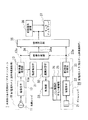
図1は本発明に係る監視用ビデオカメラシステムを示した構成図、
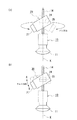
図2は第1監視カメラの後面側に設けた支持軸にパン機構部及びチルト機構部を介して第2監視カメラを取り付けた状態を示した図であり、(a)は第1監視カメラに取り付けた支持軸を中心にして第2監視カメラをパンさせる場合を示し、(b)は第2監視カメラをチルトさせる場合を示した図、
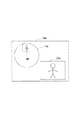
図3は本発明に係る監視用ビデオカメラシステムにおいて、第1監視カメラで撮影した全体映像に対応した全体映像データと、第2監視カメラで撮影した部分ズーム映像に対応した部分ズーム映像データとを映像合成部で合成した合成映像データを示した図、
図4は本発明に係る監視用ビデオカメラシステムにおいて、動き検出部の動作を説明するためのブロック図、
図5は本発明に係る監視用ビデオカメラシステムにおいて、座標計算部の動作を説明するための第1態様図、
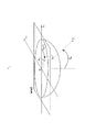
図6は本発明に係る監視用ビデオカメラシステムにおいて、座標計算部の動作を説明するための第2態様図、
図7は本発明に係る監視用ビデオカメラシステムの全体動作を説明するためのフロー図である。
【0019】
図1に示した如く、本発明に係る監視用ビデオカメラシステム1では、例えば室内の天井近傍に固定設置されて広視野な全体映像を一度に撮影できる全体映像撮影用の第1監視カメラ10と、この第1監視カメラ10で撮影した全体映像中から例えば動きのある部分を拡大して撮影できる部分ズーム映像撮影用の第2監視カメラ20とが設けられている。
【0020】
上記した第1監視カメラ10は、広視野な全体映像を撮影するための魚眼レンズ11と、この魚眼レンズ11で撮影した全体映像を結像するためにCCD又はCMOSなどを用いた撮像素子12と、撮像素子12に結像した全体映像を光電変換した後にA/D変換またはカラーマトリクス変換,ガンマ補正,アパーチャ補正などを行って、上記した全体映像に対応した全体映像データ13aを生成する第1映像処理部13とで構成されている。尚、広視野な全体映像を撮影する魚眼レンズ11に代えて、これと同等に広視野な全体映像を撮影できる広角レンズとか、双曲面ミラー,放物面ミラー,円錐ミラーなどの非球面ミラーを用いても良い。
【0021】
一方、上記した第2監視カメラ20は、第1監視カメラ10で撮影した全体映像に対応した全体映像データ13a中で動きのある部分と対応した動体を拡大して部分ズーム映像を撮影するズームレンズ21と、このズームレンズ21で撮影した部分ズーム映像を結像するためにCCD又はCMOSなどを用いた撮像素子22と、撮像素子22に結像した部分ズーム映像を光電変換した後にA/D変換またはカラーマトリクス変換,ガンマ補正,アパーチャ補正などを行って、上記した部分ズーム映像に対応した部分ズーム映像データ23aを生成する第2映像処理部23と、第2監視カメラ20をパン方向に回転させるパン機構部24と、第2監視カメラ20をチルト方向に回動させるチルト機構部25とで構成されている。
【0022】
ここで、図2(a)に拡大して示した如く、第1監視カメラ10は室内の天井近傍に固定設置されており、魚眼レンズ11が下方を向いているために室内で広視野な全体映像を一度に撮影できるようになっている。また、第1監視カメラ10の後面側には支持軸14がこの第1監視カメラ10の光軸Kの延長線上に略沿って延出されており、この支持軸14にパン機構部24及びチルト機構部25を介して第2監視カメラ20が取り付けられている。そして、支持軸14を中心にして第2監視カメラ20がパン機構部24により矢印のパン方向に360°回転できるように支持されている。これにより、第1監視カメラ10の魚眼レンズ11で撮影した全体映像中でとくに円形な魚眼画像の外周近傍に動体がある場合にこの動体を確実に追従できる。
【0023】
また、図2(b)に拡大して示したように、第2監視カメラ20は、チルト機構部25により矢印のチルト方向に所定の角度回動できるように支持軸14に支持されている。この際、チルトA側の移動量は、少なくとも全体映像内をカバーする駆動範囲を持っている。また、チルトB側の移動量は、全体映像内全てをカバーすることが望ましいが、ある移動量以上になると支持軸14への取り付け上、第2監視カメラ20で撮影した部分ズーム映像の視界の中に第1監視カメラ10が入ってしまうことになるため、第1監視カメラ10が視界に入らない範囲で動きを制限するようにしている。そのため、第2監視カメラ20で得られる部分ズーム映像に死角が存在するわけであるが、この死角になる範囲の映像は第1監視カメラ10の魚眼レンズ11によって充分な大きさの映像として得ることが可能であるため問題にはならない。言い換えると、第2監視カメラ20のズームレンズ21で部分ズーム映像を撮影する場合に支持軸14が邪魔になって、第1監視カメラ10の光軸方向(真下方向)に対して撮影しにくい範囲が僅かにあるものの、この僅かな範囲は第1監視カメラ10の魚眼レンズ11で最も大きく写る範囲であるために、この範囲はズームレンズ21からの映像を用いないで、魚眼レンズ11の映像でも十分足り得るものである。
【0024】
従って、第1監視カメラ10の後面側でこの第1監視カメラ10の光軸Kの延長線上に略沿って設けた支持軸14に、パン機構部24びチルト機構部25を介して第2監視カメラ20を取り付けることで、第1監視カメラ10で撮影した全体映像と対応した全体映像データ中から動体を検出した際に、後述するように第2監視カメラ20で拡大して撮影する動体の座標計算を第1監視カメラ10の光軸Kを基準に設定できるので動体の座標位置を簡単に計算でき、この結果、第2監視カメラ20で動体を拡大しながら迅速且つ確実に追従できる。更に、本発明に係る監視用ビデオカメラシステム1を設置する際に場所も取らず設置することができる。
【0025】
図1に戻り、第1監視カメラ10内の第1映像処理部13で処理された全体映像データ13aは、動き検出部31と、映像合成部34と、映像選択部35とに送られている。一方、第2監視カメラ20内の第2映像処理部23で処理された部分ズーム映像データ23aは、映像合成部34と、映像選択部35とに送られている。
【0026】
ここで、動き検出部31は、前フレームの全体映像データ13aを記憶した画像メモリの内容と、現在入力している全体映像データ13aとを比較し、全体映像データ13a中のどの領域が動き部分であるかを検出し、ここで検出した動き部分を座標計算部32に出力している。
【0027】
次に、座標計算部32では、動き検出部31で検出した動き部分に基づいて、動き部分の中心の絶対座標と動き部分の画角を計算して、動き部分の中心の絶対座標値と動き部分の画角値とを制御部33に送っている。
【0028】
次に、制御部33では、第1監視カメラ10で撮影した全体映像データ13a中の動き部分と対応した動体を第2監視カメラ20で適切な大きさで撮影できるようにズームレンズ21を駆動制御すると共に、動き検出部31で動きがあると検出された動体側に向かって第2監視カメラ20をパン機構部24及び/又はチルト機構部25によりパン方向及び/又はチルト方向に駆動制御している。
【0029】
次に、前記した映像合成部34では、第1監視カメラ10内の第1映像処理部13で処理された全体映像データ13aと、図3に示したように全体映像データ13a中で動きのある部分と対応した動体MVを第2監視カメラ20のズームレンズ21で拡大して撮影した後に第2映像処理部23で処理された部分ズーム映像データ23aとを合成して図3に示したような合成映像データ34aを生成し、この合成映像データ34aを映像選択部35に送っている。この際、合成映像データ34a中の全体映像データ13aと部分ズーム映像データ23aの各大きさ及び各合成位置は、図示しない外部コントローラによって制御しても良い。
【0030】
再び図1に戻り、映像選択部35では、第1監視カメラ10内の第1映像処理部13で処理された全体映像データ13aと、第2監視カメラ20内の第2映像処理部23で処理された部分ズーム映像データ23aと、映像合成部34で合成された合成映像データ34aの少なくとも一つ以上を選択している。これにより、全体映像データ13aと、部分ズーム映像データ23aと、合成映像データ34aの少なくとも一つ以上を選択できるため、監視用ビデオカメラシステム1の使用勝手が良好となる。
【0031】
尚、映像選択部35は、第1監視カメラ10の魚眼レンズ11で撮影した全体映像に対して第1映像処理部13で処理された全体映像データ13a中に動き部分がない場合には全体映像データ13aを出力し、一方、全体映像データ13a中に動き部分がある場合には第2監視カメラ20のズームレンズ21で撮影した部分ズーム映像に対して第2映像処理部23で処理された部分ズーム映像データ23aを出力するように制御することも可能であり、且つ、必要に応じて両者の合成映像データ34aを図示しない外部コントローラでの操作などにより出力すれば良いものである。
【0032】
そして、映像選択部35で選択した映像データを記録再生装置36内で不図示の磁気テープとか磁気ディスク(HDD)とかもしくは光ディスクなどの記録媒体に記録したり、又は、選択した映像データをモニタディスプレイ37上に表示している。この際、記録再生装置36は、動き検出部31で全体映像データ13a中に動き部分があると検出した場合のみ、動体を撮影した日時を記録媒体上に付加しながら部分ズーム映像データ23a又は合成映像データ34aを記録するように制御すれば、記録媒体の記録領域に対して有効利用を図ることができる。尚、記録再生装置36で記録媒体に記録済みの映像データを再生した時に、再生映像データをモニタディスプレイ37上に表示可能になっている。
【0033】
この際、第1映像処理部13,第2映像処理部23,映像合成部34の出力形態は2種類あり、一つの出力形態は標準テレビ信号のようなアナログ出力であり、アナログ出力は、その性格上映像データを1種類のみ送ることができる。即ち、全体映像データ13aと部分ズーム映像データ23aとを合成した合成映像データ34a,全体映像データ13a,部分ズーム映像データ23aのいずれかである。
【0034】
また、映像合成部34のもう一つの出力形態は、高速ディジタル出力である。記録再生装置36が映像データを2倍以上の速さで記録できるHDD搭載の装置であったり、映像の圧縮機能を兼ね備えたものであれば、全体映像データ13aと部分ズーム映像データ23aのどちらだけでなく、全体映像データ13aと部分ズーム映像データ23aの両方を記録することが可能である。このように全体映像データ13aと部分ズーム映像データ23aの両方を記録した場合、そのまま再生すると、全体映像データ13aと部分ズーム映像23aとが交互に再生されることになり、著しく醜い映像になる。そこで、記録再生装置36に記録する前に全体映像データ13aと部分ズーム映像データ23aの中に、そのどちらの映像データであるかを示すIDを記録する。このIDは、例えばMPEGのような圧縮標準の場合には、ユーザデータ領域にデータとして入れておいても良い。記録再生装置36での再生時には、このIDデータに従い、どちらか一方の映像データを出力するように制御することができる。
【0035】
ここで、前記した動き検出部31の動作について、図4を用いて詳述する。 図4に示した如く、動き検出部31は、この内部に画像メモリ31Aと、差分演算部31Bと、2値化処理部31Cと、孤立点除去部31Dと、ラベリング部31Eと、グループ化部31Fと、再ラベリング部31Gとが上記した順に設けられている。
【0036】
そして、動き検出部31では、まず、第1映像処理部13で処理された全体映像データ13aが画像メモリ31Aにフレーム単位で逐次格納されると共に、Nフレーム前の全体映像データ13aを差分演算部31Bに出力している。この際、画像メモリ31Aは全体映像データ13aをN(但し、Nは1以上の自然数)フレーム分に亘って格納可能であって、Nフレーム期間の遅延素子としての役目を担っている。従って、図示しない外部コントローラでN=1に設定した際には刻々と変わる全体映像データ13aの1フレーム前の全体映像データ13aを画像メモリ31Aに順次格納する場合であり、一方、図示しない外部コントローラでN=Nに設定した際には例えば動きのない全体映像データ13aを参照画像として画像メモリ31Aを予め格納する場合であり、どちらの場合を採用するかは適宜決めれば良いものである。
【0037】
上記した差分演算部31Bでは、第1映像処理部13でからの現フレームの全体映像データ13aと画像メモリ31Aから出力されるNフレーム前の全体映像データ13aとの差分を取って、差分全体映像データを2値化処理部31Cに出力している。
【0038】
上記した2値化処理部31Cでは、差分演算部31Bから出力された差分全体映像データに対して、差分の絶対値が予め設定した閾値より大きい画素を1、それ以外の画素を0とする2値化画像データを作成し、この2値化画像データを孤立点除去部31Dに出力している。即ち、2値化画像データ中で動き検出された画素は1となる。
【0039】
上記した孤立点除去部31Dでは、2値化処理部12Cから出力された2値化画像データ中の小面積領域はノイズ成分であるとみなせるので、領域縮小処理と領域拡大処理を複数回繰り返して小面積領域を除去し、小面積領域を除去されて残った領域をラベリング部31Eに出力している。
【0040】
上記したラベリング部31Eでは、孤立点除去部31Dにより小面積領域を除去されて残った領域に対して各領域を区別するために番号付けを行い、グループ化部31Fに出力している。
【0041】
上記したグループ化部31Fでは、距離の近い領域同士は同一の動体に属するとみなして、各領域のグループ化を行い、再ラベリング部31Gに出力している。
【0042】
上記した再ラベリング部31Gでは、各グループに対して番号付けを行って、全体映像データ13a中から検出した動きのある部分を座標計算部32に出力している。
【0043】
次に、前記した座標計算部32の動作について、図5及び図6を用いて詳述する。座標計算は、全方位映像撮像部の射影方式に用いる魚眼レンズやミラーによって異なってくるが、基本的な考え方は同じであるので、等距離射影方式の魚眼レンズ11(図1,図2)を用いた場合について以下説明する。
【0044】
図5に示した如く、第1監視カメラ10の魚眼レンズ11(図1,図2)の撮像面をxy座標で表した際に、魚眼画像の中心を中心点O、水平方向をx軸、垂直方向をy軸とする。
【0045】
また、図6に示すように、実空間をXYZ座標で表した際に、Z軸を魚眼レンズ11の光軸K(図2)に取り、且つ、X軸及びY軸は魚眼レンズ11の撮像面上に取ると、前記したX軸及びY軸は撮像面上のx軸及びy軸に一致する。また、C’点が撮像面上のC点に射影され、魚眼画像の中心点OとC’点を結んだ線OC’が魚眼画像の半径を有する半球と交差する点をC”とする。
【0046】
ここで図5及び図6を併用して説明すると、魚眼レンズ11の撮像面上で各グループに属する2値化領域に対して、まず、魚眼画像の中心点Oから最も遠い距離R0と最も近い距離R1、及び、基準となるX軸からの角度の最大角度値T0と最小角度値T1とを求める。更に、魚眼画像の中心点Oから2値化領域の中心までの距離をRcとし、且つ、X軸から2値化領域の中心までの角度をTcとすると共に、撮像面上での2値化領域の中心の座標を(xc,yc)とすると、2値化領域の中心の座標(xc,yc)は、下記の式(1),式(2)で求められる。
【0047】
Rc=(R0+R1)/2
Tc=(T0+T1)/2
xc=Rc×cosTc ……式(1)
yc=Rc×sinTc ……式(2)
また、第1監視カメラ10の魚眼レンズ11の光軸Kを2値化領域の中心に向けるとすると、その方向は、下記の式(3)で求めることができる。この際、Taをxy平面上でx軸とOCとのなす角度とし、且つ、Saを実空間内でZ軸とOC’とのなす角度とすると共に、Rfを撮影面上の魚眼画像の半径とする。
【0048】
Ta=Tc
Sa=Rc/Rf×π/2 ……式(3)
また、動き領域の水平,垂直方向の画角をそれぞれdTa,dSaとすると、動き領域の水平,垂直方向の画角dTa,dSaは、下記の式(4),式(5)で求められる。
【0049】
dTa=arccos{sinSa×sinSa×(cosT0×cosT1)+sinSa×sinSa×(sinT0×sinT1)+cosSa×cosSa} ……式(4)
dSa=(R0−R1)/Rf×π/2 ……式(5)
従って、魚眼レンズ11の画角はdTa,dSaより少し大きくなるように設定すればよい。
【0050】
この際、動き領域のグループが複数存在する場合は、撮影する領域を選択することが必要になる。選択はユーザーが行っても良いし、または、面積が最大となる領域を選択する等のルールを基に自動的に選択させることもできる。
【0051】
次に、本発明に係る監視用ビデオカメラシステム1の全体動作について、図1及び図7を併用して説明する。
【0052】
本発明に係る監視用ビデオカメラシステム1の動作を開始すると、ステップ1で第1監視カメラ10の魚眼レンズ11により全体映像を撮影し、この第1監視カメラ10内の第1映像処理部13で処理された全体映像データ13aが動き検出部31に送られる。
【0053】
次に、ステップ2では、動き検出部31内で全体映像データ13a中に動き部分があるか否かを問い、全体映像データ13a中に動き部分がないと判断された場合にはステップ5で映像選択部35を介して全体映像データ13aを出力する。
【0054】
次に、ステップ2において全体映像データ13a中に動き部分があると判断された場合には、ステップ3で座標計算部32により全体映像データ13a中で動き部分の領域を計算して動き部分と対応する動体の座標位置を求める。
【0055】
次に、ステップ4では、座標計算部32の計算結果に基づいて制御部33を介して第2監視カメラ20のズームレンズ21をパン機構部24及び/又はチルト機構部25の駆動制御により動体側に向け、この動体を拡大して部分ズーム映像を撮影し、この部分ズーム映像に対して第2監視カメラ20内の第2映像処理部23で処理された部分ズーム映像データ23aをステップ5で映像選択部35を介して出力すると共に、ステップ1に戻って上記したステップ1〜5を繰り返している。
【0056】
これにより、第1監視カメラ10で撮影した全体映像中に動体がある場合に第2監視カメラ20で動体を拡大して撮影することで動体を自動的に追従できる。
【0057】
【発明の効果】
以上詳述した本発明に係る監視用ビデオカメラシステムにおいて、請求項1記載によると、広視野な全体映像を撮影する第1監視カメラと、前記第1監視カメラで撮影した前記全体映像に対応した全体映像データ中から動きのある部分を検出する動き検出手段と、前記動き検出手段で検出した前記動きのある部分の領域を算出する座標計算手段と、前記座標計算手段からの計算結果に基づいて制御部を介してパン機構部及び/又はチルト機構部を駆動制御することで前記動きのある部分と対応する動体側に向けられ、該動体を拡大して部分ズーム映像を撮影する第2監視カメラとを備え、前記第1監視カメラの後面側で該第1監視カメラの光軸の延長線上に略沿って設けた支持軸に前記パン機構部及び前記チルト機構部を介して第2監視カメラを取り付けたため、この結果、第1監視カメラで撮影した全体映像と対応した全体映像データ中から動体を検出した際に、第2監視カメラで拡大して撮影する動体の座標計算を第1監視カメラの光軸Kを基準に設定できるので動体の座標位置を簡単に計算でき、第2監視カメラで動体を拡大しながら迅速且つ確実に追従できる。とくに、第1監視カメラに例えば魚眼レンズを取り付けた場合に、魚眼レンズで撮影した全体映像中でとくに円形な魚眼画像の外周近傍に動体がある場合にこの動体を確実に追従できる。更に、本発明に係る監視用ビデオカメラシステムを設置する際に場所も取らず設置することができる。
【0058】
また、請求項2記載によると、広視野な全体映像を撮影する第1監視カメラと、前記第1監視カメラで撮影した前記全体映像に対応した全体映像データ中から動きのある部分を検出する動き検出手段と、前記動き検出手段で検出した前記動きのある部分の領域を算出する座標計算手段と、前記座標計算手段からの計算結果に基づいて制御部を介してパン機構部及び/又はチルト機構部を駆動制御することで前記動きのある部分と対応する動体側に向けられ、該動体を拡大して部分ズーム映像を撮影する第2監視カメラと、前記全体映像データと、前記部分ズーム映像に対応した部分ズーム映像データとを合成して合成映像データを生成する映像合成手段と、前記全体映像データと、前記部分ズーム映像データと、前記合成映像データとを選択的に出力する映像選択手段とを備えたため、この結果、全体映像データと、部分ズーム映像データと、合成映像データの少なくとも一つ以上を選択できるため、監視用ビデオカメラシステムの使用勝手が良好となる。
【図面の簡単な説明】
【図1】本発明に係る監視用ビデオカメラシステムを示した構成図である。
【図2】第1監視カメラの後面側に設けた支持軸にパン機構部及びチルト機構部を介して第2監視カメラを取り付けた状態を示した図であり、(a)は第1監視カメラに取り付けた支持軸を中心にして第2監視カメラをパンさせる場合を示し、(b)は第2監視カメラをチルトさせる場合を示した図である。
【図3】本発明に係る監視用ビデオカメラシステムにおいて、第1監視カメラで撮影した全体映像に対応した全体映像データと、第2監視カメラで撮影した部分ズーム映像に対応した部分ズーム映像データとを映像合成部で合成した合成映像データを示した図である。
【図4】本発明に係る監視用ビデオカメラシステムにおいて、動き検出部の動作を説明するためのブロック図である。
【図5】本発明に係る監視用ビデオカメラシステムにおいて、座標計算部の動作を説明するための第1態様図である。
【図6】本発明に係る監視用ビデオカメラシステムにおいて、座標計算部の動作を説明するための第2態様図である。
【図7】本発明に係る監視用ビデオカメラシステムの全体動作を説明するためのフロー図である。
【図8】従来の自動追尾監視装置を示した構成図である。
【符号の説明】
1…監視用ビデオカメラシステム、
10…第1監視カメラ、11…魚眼レンズ、12…撮像素子、
13…第1映像処理部、
20…第2監視カメラ、21…ズームレンズ、22…撮像素子、
23…第2映像処理部、24…パン機構部、25…チルト機構部、
31…動き検出部、32…座標計算部、33…制御部3、34…映像合成部、
35…映像選択部、36…記録再生装置、37…モニタディスプレイ。[0001]
TECHNICAL FIELD OF THE INVENTION
The present invention relates to a surveillance video camera system used for crime prevention, disaster prevention, safety surveillance, etc., which can simultaneously capture a wide-field whole image and a partially zoomed image obtained by enlarging a moving part in the whole image. Things.
[0002]
[Prior art]
Conventional surveillance cameras are generally installed fixedly to the area to be monitored, and constantly monitor the area to be monitored, but when it is necessary to photograph a wider area, A method in which a plurality of surveillance cameras are fixedly arranged in each direction of an area to be monitored, a method in which a single surveillance camera changes a shooting direction using a pan mechanism and a tilt mechanism, and the like are employed.
[0003]
However, the method of fixedly arranging a plurality of surveillance cameras not only increases the cost of the surveillance video camera system but also necessitates securing an installation place for the plurality of surveillance cameras and complicates wiring. On the other hand, a single surveillance camera equipped with a pan mechanism and a tilt mechanism is advantageous in terms of price and installation because it does not require a number of cameras, but it is not possible to capture peripheral images at once. There are drawbacks.
[0004]
A video camera using a fisheye lens or an aspherical mirror (hyperbolic mirror, parabolic mirror, conical mirror, etc.) is known as a method for capturing a wide field of view at a time. Since the whole image was condensed into one small image sensor, the amount of information was not enough to obtain detailed video information from the image sensor, and a part of the captured image information was enlarged by electronic zoom processing. In this case, an image having a low resolution is obtained, and a satisfactory image cannot be obtained in a surveillance camera application requiring identification of a person.
[0005]
Therefore, there is an automatic tracking monitoring device (= surveillance video camera system) capable of simultaneously capturing a wide-field whole image and a partial zoom image obtained by enlarging a moving part in the whole image (for example, Patent Document 1). reference).
[0006]
[Patent Document 1]
JP-A-6-217316 (page 2-3, FIG. 1)
[0007]
FIG. 8 is a configuration diagram showing a conventional automatic tracking monitoring device.
The conventional automatic
[0008]
As shown in FIG. 8, in the conventional automatic
[0009]
Here, a moving object is detected by a motion detecting means (not shown) from the whole video taken by the lens of the
[0010]
[Problems to be solved by the invention]
By the way, in the conventional automatic
[0011]
Therefore, if the
[0012]
Therefore, both in the case where the
[0013]
Further, the conventional automatic
[0014]
Therefore, a surveillance video camera system that can solve the above-described problems has been desired.
[0015]
[Means for Solving the Problems]
The present invention has been made in view of the above problems, and a first invention is a first surveillance camera that captures a wide-field whole image,
Motion detection means for detecting a moving portion from the whole video data corresponding to the whole video captured by the first monitoring camera;
Coordinate calculation means for calculating the area of the part with the motion detected by the motion detection means,
By controlling the driving of the pan mechanism and / or the tilt mechanism via the control unit based on the calculation result from the coordinate calculation means, the pan mechanism and / or the tilt mechanism are directed to the moving body corresponding to the moving part, and the moving body is enlarged. A second surveillance camera that shoots a partial zoom image
The second surveillance camera is attached to a support shaft provided substantially along the extension of the optical axis of the first surveillance camera on the rear side of the first surveillance camera via the pan mechanism and the tilt mechanism. This is a surveillance video camera system.
[0016]
Further, a second invention is a first surveillance camera that shoots a wide-field whole image,
Motion detection means for detecting a moving portion from the whole video data corresponding to the whole video captured by the first monitoring camera;
Coordinate calculation means for calculating the area of the part with the motion detected by the motion detection means,
By controlling the driving of the pan mechanism and / or the tilt mechanism via the control unit based on the calculation result from the coordinate calculation means, the pan mechanism and / or the tilt mechanism are directed to the moving body corresponding to the moving part, and the moving body is enlarged. A second surveillance camera that captures partial zoom images
A video synthesizing unit that synthesizes the entire video data and the partial zoom video data corresponding to the partial zoom video to generate composite video data;
A video camera system for surveillance, comprising: video selection means for selectively outputting the whole video data, the partial zoom video data, and the composite video data.
[0017]
BEST MODE FOR CARRYING OUT THE INVENTION
Hereinafter, an embodiment of a surveillance video camera system according to the present invention will be described in detail with reference to FIGS.
[0018]
FIG. 1 is a configuration diagram showing a surveillance video camera system according to the present invention,
FIG. 2 is a diagram showing a state in which a second monitoring camera is attached to a support shaft provided on a rear surface side of the first monitoring camera via a pan mechanism and a tilt mechanism, and FIG. FIG. 3B shows a case where the second surveillance camera is panned around the attached support shaft, and FIG. 3B is a diagram showing a case where the second surveillance camera is tilted;
FIG. 3 is a schematic diagram of the surveillance video camera system according to the present invention, in which the whole video data corresponding to the whole video taken by the first surveillance camera and the partial zoom video data corresponding to the partial zoom video taken by the second surveillance camera. A diagram showing composite video data synthesized by the video synthesis unit,
FIG. 4 is a block diagram for explaining the operation of a motion detection unit in the surveillance video camera system according to the present invention;
FIG. 5 is a first aspect diagram for explaining the operation of the coordinate calculation unit in the surveillance video camera system according to the present invention;
FIG. 6 is a second aspect diagram for explaining the operation of the coordinate calculation unit in the surveillance video camera system according to the present invention,
FIG. 7 is a flowchart for explaining the overall operation of the surveillance video camera system according to the present invention.
[0019]
As shown in FIG. 1, a surveillance
[0020]
The
[0021]
On the other hand, the
[0022]
Here, as shown in an enlarged manner in FIG. 2A, the
[0023]
2B, the
[0024]
Accordingly, a second monitoring mechanism is provided via a
[0025]
Returning to FIG. 1, the
[0026]
Here, the
[0027]
Next, the coordinate
[0028]
Next, the
[0029]
Next, in the
[0030]
Returning to FIG. 1 again, in the
[0031]
In addition, the
[0032]
Then, the video data selected by the
[0033]
At this time, there are two types of output modes of the first
[0034]
Another output form of the
[0035]
Here, the operation of the
[0036]
In the
[0037]
The
[0038]
In the above-described
[0039]
In the above-described isolated
[0040]
In the above-described
[0041]
In the above-described
[0042]
In the
[0043]
Next, the operation of the coordinate
[0044]
As shown in FIG. 5, when the imaging surface of the fisheye lens 11 (FIGS. 1 and 2) of the
[0045]
As shown in FIG. 6, when the real space is represented by XYZ coordinates, the Z axis is taken as the optical axis K (FIG. 2) of the
[0046]
Here, the description will be made with reference to FIGS. 5 and 6. First, the distance R that is the farthest from the center point O of the fisheye image to the binarized region belonging to each group on the imaging surface of the
[0047]
Rc= (R0+ R1) / 2
Tc= (T0+ T1) / 2
xc= Rc× cosTc ...... Equation (1)
yc= Rc× sinTc ...... Equation (2)
Further, assuming that the optical axis K of the
[0048]
Ta= Tc
Sa= Rc/ Rf× π / 2 Equation (3)
In addition, the horizontal and vertical angles of view of the motion area are each set to dT.a, DSaThen, the horizontal and vertical angles of view dT of the motion areaa, DSaIs obtained by the following equations (4) and (5).
[0049]
dTa= Arccos @ sinSa× sinSa× (cosT0× cosT1) + SinSa× sinSa× (sinT0× sinT1) + CosSa× cosSa} ... Equation (4)
dSa= (R0-R1) / Rf× π / 2 ...... Equation (5)
Therefore, the angle of view of the
[0050]
At this time, when there are a plurality of groups of motion regions, it is necessary to select a region to be photographed. The selection may be performed by the user, or may be automatically selected based on a rule such as selecting a region having the largest area.
[0051]
Next, the overall operation of the surveillance
[0052]
When the operation of the surveillance
[0053]
Next, in
[0054]
Next, when it is determined in
[0055]
Next, in step 4, the
[0056]
Thus, when a moving object is present in the entire image captured by the
[0057]
【The invention's effect】
According to the surveillance video camera system according to the present invention described in detail above, according to the first aspect, a first surveillance camera that shoots a wide-view whole image and a corresponding whole image that is shot by the first surveillance camera are provided. Motion detecting means for detecting a moving part from the entire video data, coordinate calculating means for calculating an area of the moving part detected by the motion detecting means, and a calculation result from the coordinate calculating means. A second surveillance camera which is directed to a moving body corresponding to the moving part by controlling the driving of a pan mechanism unit and / or a tilt mechanism unit via a control unit, and enlarges the moving body to capture a partial zoom image. And a second surveillance camera mounted on a support shaft provided substantially along the extension of the optical axis of the first surveillance camera on the rear side of the first surveillance camera via the pan mechanism and the tilt mechanism. As a result, when a moving object is detected from the whole image data corresponding to the entire image captured by the first surveillance camera, the coordinates of the moving object to be enlarged and photographed by the second surveillance camera are calculated by the first surveillance camera. Can be set with reference to the optical axis K, so that the coordinate position of the moving object can be easily calculated, and the second surveillance camera can quickly and reliably follow the moving object while enlarging the moving object. In particular, when, for example, a fish-eye lens is attached to the first surveillance camera, the moving object can be reliably followed when the moving object is located near the outer periphery of a circular fish-eye image in the entire video taken by the fish-eye lens. Furthermore, when installing the surveillance video camera system according to the present invention, it can be installed without taking a place.
[0058]
According to the second aspect, a first surveillance camera that shoots a wide-field whole image and a motion that detects a moving part from the whole image data corresponding to the whole image shot by the first surveillance camera Detecting means; coordinate calculating means for calculating an area of the moving portion detected by the motion detecting means; and a pan mechanism and / or a tilt mechanism via a controller based on a calculation result from the coordinate calculating means. A second surveillance camera that is directed to the moving body side corresponding to the moving part by driving and controlling the part, and enlarges the moving body to capture a partial zoom image, the entire image data, and the partial zoom image. Video synthesizing means for generating synthetic video data by synthesizing the corresponding partial zoom video data, and selecting the whole video data, the partial zoom video data, and the synthetic video data As a result, it is possible to select at least one of the whole video data, the partial zoom video data, and the composite video data, so that the surveillance video camera system can be easily used. .
[Brief description of the drawings]
FIG. 1 is a configuration diagram showing a surveillance video camera system according to the present invention.
FIG. 2 is a diagram showing a state where a second surveillance camera is attached to a support shaft provided on the rear side of the first surveillance camera via a pan mechanism and a tilt mechanism, and FIG. FIG. 7B is a diagram illustrating a case where the second surveillance camera is panned around a support shaft attached to the camera, and FIG. 7B is a diagram illustrating a case where the second surveillance camera is tilted.
FIG. 3 is a diagram illustrating an entire video data corresponding to an entire video captured by a first monitoring camera and a partial zoom video data corresponding to a partial zoom video captured by a second monitoring camera in the monitoring video camera system according to the present invention; FIG. 5 is a diagram showing composite video data obtained by combining video in a video synthesis unit.
FIG. 4 is a block diagram for explaining an operation of a motion detection unit in the surveillance video camera system according to the present invention.
FIG. 5 is a first diagram illustrating the operation of a coordinate calculation unit in the surveillance video camera system according to the present invention.
FIG. 6 is a second diagram illustrating the operation of the coordinate calculation unit in the surveillance video camera system according to the present invention.
FIG. 7 is a flowchart for explaining the overall operation of the surveillance video camera system according to the present invention.
FIG. 8 is a configuration diagram showing a conventional automatic tracking monitoring device.
[Explanation of symbols]
1. Surveillance video camera system,
10: First surveillance camera, 11: Fisheye lens, 12: Image sensor,
13: first video processing unit,
20: second surveillance camera, 21: zoom lens, 22: image sensor,
23: second video processing unit, 24: pan mechanism unit, 25: tilt mechanism unit,
31: motion detection unit, 32: coordinate calculation unit, 33:
35: video selection unit, 36: recording / reproducing device, 37: monitor display.
Claims (2)
前記第1監視カメラで撮影した前記全体映像に対応した全体映像データ中から動きのある部分を検出する動き検出手段と、
前記動き検出手段で検出した前記動きのある部分の領域を算出する座標計算手段と、
前記座標計算手段からの計算結果に基づいて制御部を介してパン機構部及び/又はチルト機構部を駆動制御することで前記動きのある部分と対応する動体側に向けられ、該動体を拡大して部分ズーム映像を撮影する第2監視カメラとを備え、
前記第1監視カメラの後面側で該第1監視カメラの光軸の延長線上に略沿って設けた支持軸に前記パン機構部及び前記チルト機構部を介して第2監視カメラを取り付けたことを特徴とする監視用ビデオカメラシステム。A first surveillance camera that captures a wide field of view,
Motion detection means for detecting a moving portion from the whole video data corresponding to the whole video captured by the first monitoring camera;
Coordinate calculation means for calculating the area of the part with the motion detected by the motion detection means,
By controlling the driving of the pan mechanism and / or the tilt mechanism via the control unit based on the calculation result from the coordinate calculation means, the pan mechanism and / or the tilt mechanism are directed to the moving body corresponding to the moving part, and the moving body is enlarged. A second surveillance camera that shoots a partial zoom image
The second surveillance camera is attached to a support shaft provided substantially along the extension of the optical axis of the first surveillance camera on the rear side of the first surveillance camera via the pan mechanism and the tilt mechanism. Surveillance video camera system.
前記第1監視カメラで撮影した前記全体映像に対応した全体映像データ中から動きのある部分を検出する動き検出手段と、
前記動き検出手段で検出した前記動きのある部分の領域を算出する座標計算手段と、
前記座標計算手段からの計算結果に基づいて制御部を介してパン機構部及び/又はチルト機構部を駆動制御することで前記動きのある部分と対応する動体側に向けられ、該動体を拡大して部分ズーム映像を撮影する第2監視カメラと、
前記全体映像データと、前記部分ズーム映像に対応した部分ズーム映像データとを合成して合成映像データを生成する映像合成手段と、
前記全体映像データと、前記部分ズーム映像データと、前記合成映像データとを選択的に出力する映像選択手段とを備えたことを特徴とする監視用ビデオカメラシステム。A first surveillance camera that captures a wide field of view,
Motion detection means for detecting a moving portion from the whole video data corresponding to the whole video captured by the first monitoring camera;
Coordinate calculation means for calculating the area of the part with the motion detected by the motion detection means,
By controlling the driving of the pan mechanism and / or the tilt mechanism via the control unit based on the calculation result from the coordinate calculation means, the pan mechanism and / or the tilt mechanism are directed to the moving body corresponding to the moving part, and the moving body is enlarged. A second surveillance camera that captures partial zoom images
A video synthesizing unit that synthesizes the entire video data and the partial zoom video data corresponding to the partial zoom video to generate composite video data;
A video camera system for surveillance, comprising: video selection means for selectively outputting the whole video data, the partial zoom video data, and the composite video data.
Priority Applications (1)
| Application Number | Priority Date | Filing Date | Title |
|---|---|---|---|
| JP2002370436A JP2004201231A (en) | 2002-12-20 | 2002-12-20 | Monitoring video camera system |
Applications Claiming Priority (1)
| Application Number | Priority Date | Filing Date | Title |
|---|---|---|---|
| JP2002370436A JP2004201231A (en) | 2002-12-20 | 2002-12-20 | Monitoring video camera system |
Publications (1)
| Publication Number | Publication Date |
|---|---|
| JP2004201231A true JP2004201231A (en) | 2004-07-15 |
Family
ID=32766365
Family Applications (1)
| Application Number | Title | Priority Date | Filing Date |
|---|---|---|---|
| JP2002370436A Withdrawn JP2004201231A (en) | 2002-12-20 | 2002-12-20 | Monitoring video camera system |
Country Status (1)
| Country | Link |
|---|---|
| JP (1) | JP2004201231A (en) |
Cited By (15)
| Publication number | Priority date | Publication date | Assignee | Title |
|---|---|---|---|---|
| JP2006303989A (en) * | 2005-04-21 | 2006-11-02 | Matsushita Electric Ind Co Ltd | Monitor device |
| KR100915406B1 (en) * | 2007-11-23 | 2009-09-03 | 유장호 | Camera |
| JP2009284549A (en) * | 2009-08-31 | 2009-12-03 | Sony Corp | Information processing system, information processing apparatus, information processing method, program, and recording medium |
| US7656430B2 (en) | 2005-02-28 | 2010-02-02 | Sony Corporation | Information processing system, information processing apparatus and method, and program |
| KR200449278Y1 (en) | 2007-12-13 | 2010-06-28 | 주식회사 블랙박스 | A case and a monitoring camera having the case |
| KR100967718B1 (en) | 2009-06-02 | 2010-07-07 | 주식회사 비스타씨엔씨 | Video watch system using object recognition information |
| US7801329B2 (en) | 2005-02-28 | 2010-09-21 | Sony Corporation | Information processing system, information processing apparatus and information processing method, program, and recording medium |
| KR101019384B1 (en) | 2009-03-13 | 2011-03-07 | 중앙대학교 산학협력단 | Apparatus and method for unmanned surveillance using omni-directional camera and pan/tilt/zoom camera |
| JP2012089954A (en) * | 2010-10-15 | 2012-05-10 | Dainippon Printing Co Ltd | Conference system, monitoring system, image processing system, image processing method, and image processing program or the like |
| JP2012520650A (en) * | 2009-05-29 | 2012-09-06 | ヨングク エレクトロニクス シーオー., エルティーディー | Intelligent surveillance camera device and video surveillance system employing the same |
| KR101204080B1 (en) | 2007-07-27 | 2012-11-22 | 삼성테크윈 주식회사 | Surveillance camera system and method for controlling thereof |
| JP2013062559A (en) * | 2010-09-02 | 2013-04-04 | Dodwell Bms Ltd | Imaging monitor screen and omnidirectional imaging screen monitoring system |
| KR101330247B1 (en) | 2012-06-04 | 2013-11-15 | 주식회사 영국전자 | Method for tracking moving objects |
| WO2018109869A1 (en) * | 2016-12-14 | 2018-06-21 | 三菱電機株式会社 | Surveillance camera system and surveillance camera |
| US10992861B2 (en) | 2017-03-14 | 2021-04-27 | Nikon Corporation | Image processing device and electronic device |
-
2002
- 2002-12-20 JP JP2002370436A patent/JP2004201231A/en not_active Withdrawn
Cited By (20)
| Publication number | Priority date | Publication date | Assignee | Title |
|---|---|---|---|---|
| US7801329B2 (en) | 2005-02-28 | 2010-09-21 | Sony Corporation | Information processing system, information processing apparatus and information processing method, program, and recording medium |
| KR101215199B1 (en) | 2005-02-28 | 2012-12-24 | 소니 주식회사 | Information processing system, information processing apparatus and information processing method, and recording medium |
| US7656430B2 (en) | 2005-02-28 | 2010-02-02 | Sony Corporation | Information processing system, information processing apparatus and method, and program |
| US8041078B2 (en) | 2005-02-28 | 2011-10-18 | Sony Corporation | Information processing system, information processing apparatus and information processing method, program, and recording medium |
| JP2006303989A (en) * | 2005-04-21 | 2006-11-02 | Matsushita Electric Ind Co Ltd | Monitor device |
| JP4722537B2 (en) * | 2005-04-21 | 2011-07-13 | パナソニック株式会社 | Monitoring device |
| KR101204080B1 (en) | 2007-07-27 | 2012-11-22 | 삼성테크윈 주식회사 | Surveillance camera system and method for controlling thereof |
| KR100915406B1 (en) * | 2007-11-23 | 2009-09-03 | 유장호 | Camera |
| KR200449278Y1 (en) | 2007-12-13 | 2010-06-28 | 주식회사 블랙박스 | A case and a monitoring camera having the case |
| KR101019384B1 (en) | 2009-03-13 | 2011-03-07 | 중앙대학교 산학협력단 | Apparatus and method for unmanned surveillance using omni-directional camera and pan/tilt/zoom camera |
| JP2012520650A (en) * | 2009-05-29 | 2012-09-06 | ヨングク エレクトロニクス シーオー., エルティーディー | Intelligent surveillance camera device and video surveillance system employing the same |
| KR100967718B1 (en) | 2009-06-02 | 2010-07-07 | 주식회사 비스타씨엔씨 | Video watch system using object recognition information |
| JP2009284549A (en) * | 2009-08-31 | 2009-12-03 | Sony Corp | Information processing system, information processing apparatus, information processing method, program, and recording medium |
| JP2013062559A (en) * | 2010-09-02 | 2013-04-04 | Dodwell Bms Ltd | Imaging monitor screen and omnidirectional imaging screen monitoring system |
| JP2012089954A (en) * | 2010-10-15 | 2012-05-10 | Dainippon Printing Co Ltd | Conference system, monitoring system, image processing system, image processing method, and image processing program or the like |
| KR101330247B1 (en) | 2012-06-04 | 2013-11-15 | 주식회사 영국전자 | Method for tracking moving objects |
| WO2018109869A1 (en) * | 2016-12-14 | 2018-06-21 | 三菱電機株式会社 | Surveillance camera system and surveillance camera |
| JPWO2018109869A1 (en) * | 2016-12-14 | 2019-04-04 | 三菱電機株式会社 | Surveillance camera system, surveillance camera |
| US10992861B2 (en) | 2017-03-14 | 2021-04-27 | Nikon Corporation | Image processing device and electronic device |
| US11716539B2 (en) | 2017-03-14 | 2023-08-01 | Nikon Corporation | Image processing device and electronic device |
Similar Documents
| Publication | Publication Date | Title |
|---|---|---|
| US9398214B2 (en) | Multiple view and multiple object processing in wide-angle video camera | |
| US9602700B2 (en) | Method and system of simultaneously displaying multiple views for video surveillance | |
| JP4140591B2 (en) | Imaging system and imaging method | |
| US20110254972A1 (en) | Imaging device | |
| JP2004201231A (en) | Monitoring video camera system | |
| JP2005311789A (en) | Digital camera | |
| JP2006245726A (en) | Digital camera | |
| JP3253478B2 (en) | Video recording device | |
| JP2007266713A (en) | Monitoring system, monitoring method, and program | |
| JP2000069352A (en) | Method and device for image input | |
| WO2016125946A1 (en) | Panorama image monitoring system using plurality of high-resolution cameras, and method therefor | |
| JPH1169288A (en) | Image processor | |
| JPH1169293A (en) | Image processing system and camcorder | |
| KR100995949B1 (en) | Image processing device, camera device and image processing method | |
| JP2009164767A (en) | Imaging apparatus and its display method | |
| US6876387B1 (en) | Digital zoom-out processing apparatus | |
| JPH09322055A (en) | Electronic camera system | |
| JP2003198902A (en) | Panoramic picture generator | |
| US8531556B2 (en) | Imaging apparatus and recording medium with program recorded therein | |
| JP3994469B2 (en) | Imaging device, display device, and recording device | |
| JP3122099B2 (en) | Image synthesizing apparatus and image synthesizing method | |
| JP2002101408A (en) | Supervisory camera system | |
| JP2008005427A (en) | Imaging apparatus and imaging method, and program | |
| JP2004088558A (en) | Monitoring system, method, program, and recording medium | |
| JP2006121320A (en) | Omnidirectional monitor camera device |
Legal Events
| Date | Code | Title | Description |
|---|---|---|---|
| A621 | Written request for application examination |
Effective date: 20051214 Free format text: JAPANESE INTERMEDIATE CODE: A621 |
|
| A761 | Written withdrawal of application |
Free format text: JAPANESE INTERMEDIATE CODE: A761 Effective date: 20060824 |