JP2004200009A - Short arc type discharge lamp - Google Patents
Short arc type discharge lamp Download PDFInfo
- Publication number
- JP2004200009A JP2004200009A JP2002367338A JP2002367338A JP2004200009A JP 2004200009 A JP2004200009 A JP 2004200009A JP 2002367338 A JP2002367338 A JP 2002367338A JP 2002367338 A JP2002367338 A JP 2002367338A JP 2004200009 A JP2004200009 A JP 2004200009A
- Authority
- JP
- Japan
- Prior art keywords
- tube
- discharge lamp
- sealing tube
- short arc
- electrode
- Prior art date
- Legal status (The legal status is an assumption and is not a legal conclusion. Google has not performed a legal analysis and makes no representation as to the accuracy of the status listed.)
- Granted
Links
Images


Classifications
-
- H—ELECTRICITY
- H01—ELECTRIC ELEMENTS
- H01J—ELECTRIC DISCHARGE TUBES OR DISCHARGE LAMPS
- H01J61/00—Gas-discharge or vapour-discharge lamps
- H01J61/84—Lamps with discharge constricted by high pressure
- H01J61/86—Lamps with discharge constricted by high pressure with discharge additionally constricted by close spacing of electrodes, e.g. for optical projection
-
- H—ELECTRICITY
- H01—ELECTRIC ELEMENTS
- H01J—ELECTRIC DISCHARGE TUBES OR DISCHARGE LAMPS
- H01J61/00—Gas-discharge or vapour-discharge lamps
- H01J61/02—Details
- H01J61/36—Seals between parts of vessels; Seals for leading-in conductors; Leading-in conductors
- H01J61/366—Seals for leading-in conductors
-
- H—ELECTRICITY
- H01—ELECTRIC ELEMENTS
- H01J—ELECTRIC DISCHARGE TUBES OR DISCHARGE LAMPS
- H01J61/00—Gas-discharge or vapour-discharge lamps
- H01J61/02—Details
- H01J61/54—Igniting arrangements, e.g. promoting ionisation for starting
- H01J61/547—Igniting arrangements, e.g. promoting ionisation for starting using an auxiliary electrode outside the vessel
Abstract
Description
【0001】
【発明の属する技術分野】
本発明は、ショートアーク型放電ランプに係わり、例えば、映写機用の光源として使用されるショートアーク型放電ランプや、半導体露光用の光源として使用される水銀が封入されたショートアーク型放電ランプに関する。
【0002】
【従来の技術】
従来、上記分野に用いられるショートアーク型放電ランプは、発光管内に電極の温度上昇を抑制し、電極の熱損耗を防止するために大きな電極が配置されている。また、電極を支持する電極棒が、発光管に続く封止管内に、封止管の絞り込み量を少なくして、封止管の破損を防止するために封止管内面に溶着して設けられた円筒状のガラス製の保持用筒体に挿入して配置されている。
【0003】
また、このようなランプは、点灯性を良くするために、トリガーワイヤーの一端が一方の封止管上に巻回され、該トリガーワイヤーの他端が発光管外表面に沿って他方の封止管上に設けられている。
【0004】
トリガーワイヤーは、一方の電極に電気的に接続して配置する場合や、いずれの電極にも接続せずに配置する場合とがあるが、どちらの場合も、電極間にイグナイターからブレークダウン電圧を印加した際に、ランプの点灯に寄与させることができるものである。
【0005】
従来、トリガーワイヤーの配設の仕方を改善して、ブレークダウン電圧の低下を図り、点灯装置の種類に関係なくショートアーク型放電ランプを確実に点灯させる技術が、特開平2−199766号公報や特開平2−210750号公報に開示されている。
【0006】
【特許文献1】
特開平2−199766号公報
【0007】
【特許文献2】
特開平2−210750号公報
【0008】
【発明が解決しようとする課題】
ところで、近年、半導体露光分野では、露光工程のスループットの向上を図るために、より一層紫外線放射強度の強いランプが要求され、また、映像分野では、スクリーン照度の向上を図るために、より一層大きなランプが要求さ、ランプ入力が大きくなる傾向にある。
そのため、このようなランプでは、電極間距離が大きくなり、封入ガス圧も高くなっている。
【0009】
電極間距離を大きくする理由は、電極間距離が短い場合は、熱によって電極先端が融け出す現象が発生するためであり、これを回避するために電極間距離を大きくする必要がある。
【0010】
また、封入ガス圧を高くする理由は、半導体露光用のランプでは、紫外線放射強度を上げるためであり、アルゴンやクリプトンやキセノン等のバッファガスの圧力を上げる手段が採られる。また、映像用のランプでは、光出力を高めるために、封入するキセノンガス量を増やす手段が採られ、封入ガス圧が高くなっている。
さらに、これらのランプにおいては、電極の形状(特に、電極の胴部の外径)が大きくなり、封止管の内径が大きくなる。そのため、封止管の絞り込み量が大きくなることを避けるために、保持用筒体の肉厚を厚くする傾向にある。
【0011】
しかし、上記のごとくランプ構造が変化すると、ブレークダウン電圧を高くしなければランプを点灯することができなくなっている。しかし、ブレークダウン電圧を大きくすると、電源に戻るサージ量、いわゆるノイズが大きくなるため、電源を破壊したり、電源の破壊を防止するための回路構成が複雑になる問題が発生する。つまり、ランプの点灯性が悪化する問題が生じる。
【0012】
本発明の目的は、上記のごとく、電極間距離が大きく、封入ガス圧も高いショートアーク型放電ランプにおいても、低いブレークダウン電圧で確実にランプを点灯させることができる、いわゆるランプの点灯性を改善したショートアーク型放電ランプを提供することにある。
【0013】
【課題を解決するための手段】
本発明は、上記の課題を解決するために、次のような手段を採用した。
第1の手段は、発光管と、該発光管に続く封止管と、前記発光管内に配置された1対の電極とからなり、前記封止管の一部よりなる支持部において前記電極を支持する電極棒を保持し、前記封止管の前記支持部外表面にトリガー部材を設けてなるショートアーク型放電ランプにおいて、少なくとも、前記封止管の前記支持部に金属または金属化合物を混入して誘電率を高めたことを特徴とする。
【0014】
第2の手段は、発光管と、該発光管に続く封止管と、前記発光管内に配置される1対の電極とからなり、前記封止管の一部よりなる支持部の内面に前記電極を支持する電極棒を保持する保持用筒体を溶着して形成し、前記封止管の前記支持部外表面にトリガー部材を設けてなるショートアーク型放電ランプにおいて、少なくとも、前記封止管の前記支持部および/または前記保持用筒体に金属または金属化合物を混入して誘電率を高めたことを特徴とする。
【0015】
第3の手段は、第1の手段または第2の手段において、前記金属化合物がチタン化合物であることを特徴とする。
【0016】
【発明の実施の形態】
本発明の実施形態を図1から図6を用いて説明する。
図1は、一実施形態に係るショートアーク型放電ランプの構成を示す断面図である。
同図において、1は発光管、2は発光管1に続く封止管、3は発光管1内に配置される1対の電極、4は電極3を支持する電極棒、5は封止管2の外表面に配設されたトリガーワイヤー等のトリガー部材、6は口金、7は封止管2が絞り込まれ、絞り込まれた封止管2の内面において電極棒4を保持する封止管2の一部よりなる支持部であり、この封止管2の支持部7には、この部分の誘電率を高めるために金属または金属化合物が混入される。
【0017】
なお、発光管1と封止管2は石英ガラスからなり、一体物で構成され、図中左側の電極3は陰極であり、電極棒4の先端側が陰極である電極3として機能するものである。また、同図に示すように、絞り込まれた封止管2の支持部7の内面において電極棒4を保持するように構成されている。また、本実施形態においては、トリガー部材5の一端が口金6に接続され、他端が封止管2の一部に巻回されたトリガー部材の配設構成を採用している。
【0018】
図2は、図1と異なる他の実施形態に係るショートアーク型放電ランプの構成を示す断面図である。
同図において、8は封止管2の支持部7の内面に溶着して設けられた円筒状のガラス製の筒体からなり、内部において電極棒4を挿通して保持する保持用筒体である。本実施形態のショートアーク型放電ランプにおいては、封止管2の支持部7および保持用筒体8には、封止管2の支持部7および保持用筒体8の誘電率を高めるための金属または金属化合物が混入されているか、または封止管2の支持部7または保持用筒体8に、封止管2の支持部7または保持用筒体8の誘電率を高めるための金属または金属化合物が混入されている
なお、その他の構成は図1に示す同符号の構成に対応するので説明を省略する。
【0019】
同図に示すように、本実施形態のショートアーク型放電ランプは、図1に示すショートアーク型放電ランプにおいては封止管2の支持部7内面において電極棒4を保持しているのに対して、封止管2の支持部7内面に設けられた保持用筒体8によって電極棒4を保持するように構成されている点で相違する。
【0020】
次に、図3および図4を用いて、ショートアーク型放電ランプのブレークダウン電圧を低下させることができる理由を、図2に示した封止管2の支持部7および保持用筒体8に金属または金属化合物を混入したショートアーク型放電ランプを例にして説明する。
【0021】
図3は、図2のA−Aにおける断面を拡大して示した断面図である。
同図において、9は保持用筒体8と電極棒4間の間隙、d1は封止管2の厚さと保持用筒体8の厚さを加算したトリガー部材5と間隙9間の距離、d0は間隙の距離であり、その他の符号は図2に示す同符号の構成に対応する。
同図に示すように、封止管2の支持部7においては、電極棒4およびトリガー部材5を両電極とし、その間に封止管2の支持部7、保持用筒体8、および間隙9が存在することによって、1つのコンデンサが形成される。
【0022】
図4は、図3に示した断面図を等価的なコンデンサとして示した図である。 ここで、封止管2の支持部7および保持用筒体8の石英ガラスにおける静電容量をC1、誘電率をε1とし、間隙9における静電容量をC0、誘電率をε0とし、電極面積をSとし、電極棒4とトリガー部材5間に印加される電位差をV、間隙9間の電位差をV0、間隙9における電界強度をE0とするとき、
C1=ε1・S/d1、C0=ε0・S/d0と表される。
その結果、
E0=V0/d0=(V/d0)・(1/C0)/(1/C0+1/C1)
=(V/d0)・(d0/ε0・S)/(d0/ε0・S+d1/ε1・
S)
=V/(d0+d1・ε0/ε1)
と表される。
【0023】
ここで、ランプの点灯性を良くすることとは、間隙9における絶縁破壊をし易くすることと同じである。つまり、上式において、間隙9における電界強度E0を大きくすることによって、間隙9における絶縁破壊が起こり易くなる。
【0024】
上式において、電界強度E0を大きくするためには、電極棒4と保持用筒体8の内面の間隙9の距離d0を小さくするか、封止管2と保持用筒体8の肉厚の合計である距離d1を小さくするか、封止管2と保持用筒体8の石英ガラスにおける誘電率ε1を大きくするかである。
この場合、距離d0を小さくすることは、電極棒4と保持用筒体8の内面との離間距離を小さくすることであるが、これは製造上一定の離間距離以下とすることはできない。また、距離d1を小さくすることは、封止管2と保持用筒体8の合計の肉厚を薄くすることになるが、この肉厚を薄くすると、封止管2の強度が落ちる問題がある。
従って、封止管2と保持用筒体8の石英ガラスにおける誘電率ε1を大きくすることが得策であることが分かる。
【0025】
このようなことから、図1に示したショートアーク型放電ランプにおいては、少なくとも、封止管2の支持部7に、封止管2の支持部7における誘電率を高めるために、金属または金属化合物を混入するものであり、また、図2に示したショートアーク型放電ランプにおいては、少なくとも、封止管2の支持部7および/または保持用筒体8に、封止管2の支持部7および/または保持用筒体8における誘電率を高めるために、金属または金属化合物を混入するものである。
なお、具体的に混入する金属化合物としてはチタン化合物であるチタン酸化物(TiO2)を用いた。
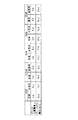
図5は、封止管と保持用筒体が共に石英ガラスからなる従来のショートアーク型放電ランプと、封止管と保持用筒体にチタン酸化物を混入した本発明のショートアーク型放電ランプについて、それぞれ異なる入力電力のランプについて、封止管と保持用筒体における比誘電率とブレークダウン電圧との対比結果を示す表である。
【0026】
同図から明らかなように、本発明の全てのショートアーク型放電ランプは、従来のショートアーク型放電ランプに比べて、封止管および保持用筒体における誘電率が大きくなっており、ブレークダウン電圧も、全ての異なる入力電力のランプにおいて、本発明の各ショートアーク型放電ランプが従来の各ショートアーク型放電ランプに比べて低くなっている。
【0027】
つまり、本発明の各ショートアーク型放電ランプでは、低いブレークダウン電圧でも確実にランプを点灯させることができ、ランプの点灯性を良くすることができる。
なお、同図に示すように、ランプの点灯性の向上は5kW以上のショートアーク型放電ランプにおいて顕著になっていることが分かる。
【0028】
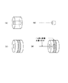
次に、図5に示された比誘電率の測定方法について説明する。
まず、比誘電率を測定するための測定サンプルの作り方について図6を用いて説明する。図6(a)に示すように、従来のショートアーク型放電ランプおよび本発明のショートアーク型放電ランプについて、図2に示したショートアーク型放電ランプの封止管2の支持部7および保持用筒体8に相当する箇所(以下、ガラスという)を切り出す。次に、切り出されたガラス中の電極棒やガラス外面に塗布されていた金属膜等を剥がし、ガラスのみの状態にする。次に、図6(b)に示すように、ガラスの内径と同径で、かつガラスの長さに比べて1/2以下の長さの金属棒を用意する。この金属棒には測定時の端子となる金属棒に比べて極めて細い金属線を溶接する。次に、図6(c)に示すように、前記金属棒と同じ幅の金属膜を図6(a)で作成されたガラスの中央部外周に塗布する。次に、図6(d)に示すように、図6(b)において作成された金属棒を図6(c)において作成されたガラス中に挿入する。その際、金属棒とガラス中央部外周の金属膜の位置が一致するようにする。これで、測定サンプルが完成する。
【0029】
次に、上記測定サンプルの静電容量の測定は、ガラス外周に塗布された金属膜と金属棒に接続されている金属線間を、LCZメータで測定する。静電容量の測定は周波数1kHzの条件下で測定した。なお、LCZメータは、NF ELECTRONIC INSTRUMENTS製のLCZ METER2340を使用した。
【0030】
次に、測定された静電容量に基づく、前記測定サンプルであるガラスの比誘電率の算出は、前記測定サンプルであるガラスは同心円筒と見なせるから、この同心円筒の中心から円筒内面までの距離をa、同心円筒の中心から円筒外面までの距離をbとし、このガラスの誘電率をεqとすると、単位長さ当たりの同心円筒の静電容量は、C=2πεq/log10b/a(F)で表すことができる。これより誘電率εq(F/m)を算出し、εq=ε1×ε0より、真空中の誘電率ε0=8.85×10−12(F/m)ε0を利用して、ガラスの比誘電率ε1を算出することができる。
【0031】
次に、図2に示したショートアーク型放電ランプのトリガー部材の配置方法と異なる配置方法について、図7から図9を用いて説明する。
【0032】
図7に示すショートアーク型放電ランプでは、トリガー部材5は、両方の口金6に接続されておらず、封止管2間に渡って配設され、両端が封止管2の支持部7において巻回されているだけである。この場合、トリガー部材5は電極3と電気的には接続されておらず、浮いた状態にある。このランプでは、電極間の絶縁破壊電圧がそれほど高くなく、イグナイターからの高電圧で絶縁破壊を起すものであり、さらに点灯性を良くするためにトリガー部材5が配置されたものである。
【0033】
図8に示すショートアーク型放電ランプは、図2に示すショートアーク型放電ランプとは異なり、トリガー部材5の一端部が図中左側の陰極となる電極3に繋がる口金6に接続されているものである。電源との関係において、陰極となる電極3がマイナス高圧になる場合に、このような配置方法が採られる。図2では、陽極となる電極3がプラス高圧になっており、陽極となる電極3に繋がる口金6にトリガー部材5が接続されている。
【0034】
図9に示すショートアーク型放電ランプは、図中左側の封止管2の表面に導電性の金属膜9が形成されており、トリガー部材5と異なるトリガー部材51の一端が図中左側の口金6に接続され、他端が支持部7の表面に巻回されている。またトリガー部材5は、封止管2間に渡って配設され、両端が封止管2の支持部7において巻回されている。そして、トリガー部材5とトリガー部材51とは、金属膜9を介して電気的に繋がっている。
【0035】
【発明の効果】
請求項1に記載の発明によれば、発光管と、発光管に続く封止管と、発光管内に配置される1対の電極とからなり、封止管の一部よりなる支持部において電極を支持する電極棒を保持し、封止管の支持部の外表面にトリガー部材を設けてなるショートアーク型放電ランプにおいて、少なくとも、封止管の支持部に金属または金属化合物を混入して誘電率を高めたので、ランプの電極間距離が大きな、また封入ガス圧も高いショートアーク型放電ランプにおいても、電極棒と封止管の支持部内面間に形成される間隙の電界強度を高めることができ、低いブレークダウン電圧でも確実にランプを点灯させることができる。
【0036】
請求項2に記載の発明によれば、発光管と、発光管に続く封止管と、発光管内に配置される1対の電極とからなり、封止管の一部よりなる支持部の内面に電極を支持する電極棒を保持する保持用筒体を溶着して形成し、封止管の支持部の外表面にトリガー部材を設けてなるショートアーク型放電ランプにおいて、少なくとも、封止管の支持部および/または保持用筒体に金属または金属化合物を混入して誘電率を高めたので、ランプの電極間距離が大きな、また封入ガス圧も高いショートアーク型放電ランプにおいても、電極棒と保持用筒体内面間に形成される間隙の電界強度を高めることができ、低いブレークダウン電圧でも確実にランプを点灯させることができる。
【0037】
請求項3に記載の発明によれば、金属化合物としてチタン化合物を用いるので、封止管の支持部および/または保持用筒体の誘電率を容易に高めることが可能である。
【図面の簡単な説明】
【図1】本発明の一実施形態に係るショートアーク型放電ランプの構成を示す断面図である。
【図2】本発明の他の実施形態に係るショートアーク型放電ランプの構成を示す断面図である。
【図3】図2のA−Aにおける断面を拡大して示した断面図である。
【図4】図3に示した断面図を等価的なコンデンサとして示した図である。
【図5】封止管と保持用筒体が共に石英ガラスからなる従来のショートアーク型放電ランプと、封止管と保持用筒体にチタン酸化物を混入した本発明のショートアーク型放電ランプについて、それぞれ異なる入力電力のランプについて、封止管と保持用筒体における比誘電率とブレークダウン電圧との対比結果を示す表である。
【図6】比誘電率を測定するための測定サンプルの作り方を説明するための図である。
【図7】図2に示したショートアーク型放電ランプのトリガー部材の配置方法と異なる配置方法を示す図である。
【図8】図2に示したショートアーク型放電ランプのトリガー部材の配置方法と異なる配置方法を示す図である。
【図9】図2に示したショートアーク型放電ランプのトリガー部材の配置方法と異なる配置方法を示す図である。
【符号の説明】
1 発光管
2 封止管
3 電極
4 電極棒
5 トリガー部材
6 口金
7 封止管の一部である支持部
8 保持用筒体
9 間隙[0001]
TECHNICAL FIELD OF THE INVENTION
The present invention relates to a short arc discharge lamp, for example, a short arc discharge lamp used as a light source for a projector and a short arc discharge lamp filled with mercury used as a light source for semiconductor exposure.
[0002]
[Prior art]
Conventionally, in a short arc type discharge lamp used in the above field, a large electrode is arranged in an arc tube in order to suppress a temperature rise of the electrode and to prevent heat loss of the electrode. Further, an electrode rod supporting the electrode is provided in the sealed tube following the arc tube by welding to the inner surface of the sealed tube to reduce the amount of narrowing of the sealed tube and prevent breakage of the sealed tube. It is inserted and placed in a cylindrical holding cylinder made of glass.
[0003]
Further, in such a lamp, one end of a trigger wire is wound on one sealing tube to improve the lighting property, and the other end of the trigger wire is sealed along the outer surface of the arc tube. It is provided on a tube.
[0004]
The trigger wire may be placed electrically connected to one of the electrodes or placed without being connected to any of the electrodes.In either case, the breakdown voltage is applied between the electrodes by an igniter. When applied, it can contribute to the lighting of the lamp.
[0005]
Conventionally, a technique of improving the arrangement of a trigger wire to reduce a breakdown voltage and reliably lighting a short arc discharge lamp regardless of the type of lighting device is disclosed in Japanese Patent Application Laid-Open No. 2-199766. It is disclosed in JP-A-2-210750.
[0006]
[Patent Document 1]
JP-A-2-199766
[Patent Document 2]
JP-A-2-210750
[Problems to be solved by the invention]
By the way, in recent years, in the field of semiconductor exposure, a lamp having an even stronger ultraviolet radiation intensity has been required in order to improve the throughput of the exposure process, and in the field of imaging, a larger lamp has been required in order to improve the screen illuminance. The demand for a lamp tends to increase the lamp input.
Therefore, in such a lamp, the distance between the electrodes is increased, and the pressure of the filled gas is also increased.
[0009]
The reason for increasing the inter-electrode distance is that when the inter-electrode distance is short, a phenomenon occurs in which the tip of the electrode melts due to heat, and it is necessary to increase the inter-electrode distance to avoid this.
[0010]
The reason for increasing the pressure of the sealed gas is to increase the intensity of ultraviolet radiation in a lamp for semiconductor exposure, and means for increasing the pressure of a buffer gas such as argon, krypton, or xenon is employed. In addition, in a video lamp, a means for increasing the amount of xenon gas to be sealed is employed in order to increase the light output, and the sealed gas pressure is increased.
Further, in these lamps, the shape of the electrode (particularly, the outer diameter of the body of the electrode) increases, and the inner diameter of the sealing tube increases. Therefore, in order to avoid an increase in the narrowing amount of the sealing tube, the thickness of the holding cylinder tends to be increased.
[0011]
However, when the lamp structure changes as described above, the lamp cannot be turned on unless the breakdown voltage is increased. However, when the breakdown voltage is increased, the amount of surge returning to the power supply, that is, so-called noise, increases, which causes a problem that the power supply is destroyed and a circuit configuration for preventing the power supply from being destroyed becomes complicated. That is, there is a problem that the lighting performance of the lamp is deteriorated.
[0012]
As described above, the object of the present invention is to provide a short arc discharge lamp having a large inter-electrode distance and a high filling gas pressure, so that the lamp can be reliably turned on at a low breakdown voltage. An object of the present invention is to provide an improved short arc discharge lamp.
[0013]
[Means for Solving the Problems]
The present invention employs the following means in order to solve the above problems.
The first means includes an arc tube, a sealing tube following the arc tube, and a pair of electrodes arranged in the arc tube. In a short arc discharge lamp in which a supporting member is held and a trigger member is provided on the outer surface of the support portion of the sealing tube, at least a metal or a metal compound is mixed into the support portion of the sealing tube. The dielectric constant is increased.
[0014]
The second means includes an arc tube, a sealing tube following the arc tube, and a pair of electrodes arranged in the arc tube. In a short arc discharge lamp in which a holding tubular body for holding an electrode rod for supporting an electrode is formed by welding and a trigger member is provided on the outer surface of the support portion of the sealed tube, at least the sealed tube Wherein a metal or a metal compound is mixed into the support portion and / or the holding cylinder to increase the dielectric constant.
[0015]
A third means is the first means or the second means, wherein the metal compound is a titanium compound.
[0016]
BEST MODE FOR CARRYING OUT THE INVENTION
An embodiment of the present invention will be described with reference to FIGS.
FIG. 1 is a sectional view showing a configuration of a short arc type discharge lamp according to one embodiment.
In the figure, 1 is an arc tube, 2 is a sealing tube following the
[0017]
The arc tube 1 and the
[0018]
FIG. 2 is a cross-sectional view showing a configuration of a short arc type discharge lamp according to another embodiment different from FIG.
In the same figure,
[0019]
As shown in the drawing, the short arc discharge lamp of the present embodiment holds the
[0020]
Next, the reason why the breakdown voltage of the short arc discharge lamp can be reduced will be described with reference to FIGS. 3 and 4 in the
[0021]
FIG. 3 is a cross-sectional view showing an enlarged cross section taken along line AA of FIG.
In the figure, the gap between the cylindrical retaining
As shown in the figure, in the
[0022]
FIG. 4 is a diagram showing the cross-sectional view shown in FIG. 3 as an equivalent capacitor. Here, C 1 and the capacitance of the quartz glass of the supporting
C 1 = ε 1 · S / d 1 , and C 0 = ε 0 · S / d 0 .
as a result,
E 0 = V 0 / d 0 = (V / d 0 ) · (1 / C 0 ) / (1 / C 0 + 1 / C 1 )
= (V / d 0 ) · (d 0 / ε 0 · S) / (d 0 / ε 0 · S + d 1 / ε 1 ·
S)
= V / (d 0 + d 1 · ε 0 / ε 1 )
It is expressed as
[0023]
Here, improving the lighting properties of the lamp is the same as facilitating dielectric breakdown in the
[0024]
In the above formula, in order to increase the electric field strength E 0 , the distance d 0 of the
In this case, reducing the distance d 0 means reducing the distance between the
Therefore, it can be seen that increasing the dielectric constant epsilon 1 of quartz glass
[0025]
For this reason, in the short arc type discharge lamp shown in FIG. 1, at least the metal or metal is provided on the
Note that titanium oxide (TiO 2 ), which is a titanium compound, was specifically used as the metal compound to be mixed.
FIG. 5 shows a conventional short arc discharge lamp in which both the sealing tube and the holding tube are made of quartz glass, and a short arc discharge lamp of the present invention in which titanium oxide is mixed into the sealing tube and the holding tube. 7 is a table showing comparison results of relative dielectric constant and breakdown voltage in a sealed tube and a holding cylinder for lamps having different input powers.
[0026]
As can be seen from the figure, all of the short arc discharge lamps of the present invention have a higher dielectric constant in the sealed tube and the holding cylinder than the conventional short arc discharge lamp, and have a breakdown. The voltage is lower in each of the short arc discharge lamps of the present invention than in each of the conventional short arc discharge lamps in all the lamps having different input powers.
[0027]
That is, in each of the short arc discharge lamps of the present invention, the lamp can be reliably turned on even at a low breakdown voltage, and the lighting performance of the lamp can be improved.
As shown in the figure, it can be seen that the improvement of the lighting performance of the lamp is remarkable in the short arc discharge lamp of 5 kW or more.
[0028]
Next, a method for measuring the relative permittivity shown in FIG. 5 will be described.
First, a method of preparing a measurement sample for measuring the relative permittivity will be described with reference to FIG. As shown in FIG. 6 (a), for the conventional short arc discharge lamp and the short arc discharge lamp of the present invention, the
[0029]
Next, the capacitance of the measurement sample is measured by using an LCZ meter between the metal film applied to the outer periphery of the glass and the metal wire connected to the metal rod. The capacitance was measured under the condition of a frequency of 1 kHz. The LCZ meter used was LCZ METER2340 manufactured by NF ELECTRONIC INSTRUMENTS.
[0030]
Next, based on the measured capacitance, the relative dielectric constant of the glass as the measurement sample is calculated by calculating the distance from the center of the concentric cylinder to the inner surface of the cylinder because the glass as the measurement sample can be regarded as a concentric cylinder. Is a, the distance from the center of the concentric cylinder to the outer surface of the cylinder is b, and the dielectric constant of this glass is ε q , the capacitance of the concentric cylinder per unit length is C = 2πε q / log 10 b / a (F). From this, the dielectric constant ε q (F / m) is calculated, and from ε q = ε 1 × ε 0 , the dielectric constant in vacuum ε 0 = 8.85 × 10 −12 (F / m) ε 0 is used. Te, it is possible to calculate the dielectric constant epsilon 1 of the glass.
[0031]
Next, an arrangement method different from the arrangement method of the trigger member of the short arc type discharge lamp shown in FIG. 2 will be described with reference to FIGS.
[0032]
In the short arc type discharge lamp shown in FIG. 7, the
[0033]
The short arc type discharge lamp shown in FIG. 8 differs from the short arc type discharge lamp shown in FIG. 2 in that one end of the
[0034]
In the short arc type discharge lamp shown in FIG. 9, a
[0035]
【The invention's effect】
According to the first aspect of the present invention, an electrode is provided at a support portion which is composed of a luminous tube, a sealing tube following the luminous tube, and a pair of electrodes arranged in the luminous tube. In a short arc type discharge lamp in which a trigger member is provided on the outer surface of the support portion of the sealed tube, the metal or metal compound is mixed at least into the support portion of the sealed tube, Because of the high efficiency, the electric field strength of the gap formed between the electrode rod and the inner surface of the support portion of the sealing tube should be increased even in a short arc discharge lamp where the distance between the electrodes of the lamp is large and the filling gas pressure is high. Thus, the lamp can be reliably turned on even at a low breakdown voltage.
[0036]
According to the second aspect of the present invention, the inner surface of the supporting portion including the arc tube, the sealing tube following the arc tube, and a pair of electrodes arranged in the arc tube, and formed by a part of the sealing tube. In a short arc discharge lamp formed by welding a holding cylinder holding an electrode rod supporting an electrode, and providing a trigger member on the outer surface of a support portion of the sealing tube, at least the sealing tube Since a metal or a metal compound is mixed into the supporting portion and / or the holding cylinder to increase the dielectric constant, even in a short arc type discharge lamp having a large distance between the electrodes of the lamp and a high filling gas pressure, the electrode rod and the metal compound are mixed. The electric field strength of the gap formed between the inner surfaces of the holding cylinder can be increased, and the lamp can be reliably turned on even at a low breakdown voltage.
[0037]
According to the third aspect of the present invention, since the titanium compound is used as the metal compound, it is possible to easily increase the dielectric constant of the supporting portion of the sealing tube and / or the holding cylinder.
[Brief description of the drawings]
FIG. 1 is a sectional view showing a configuration of a short arc type discharge lamp according to an embodiment of the present invention.
FIG. 2 is a sectional view showing a configuration of a short arc type discharge lamp according to another embodiment of the present invention.
FIG. 3 is an enlarged cross-sectional view showing a cross section taken along line AA of FIG. 2;
FIG. 4 is a diagram showing the cross-sectional view shown in FIG. 3 as an equivalent capacitor.
FIG. 5 shows a conventional short arc discharge lamp in which both a sealing tube and a holding cylinder are made of quartz glass, and a short arc discharge lamp of the present invention in which titanium oxide is mixed into the sealing tube and the holding cylinder. 3 is a table showing comparison results of relative dielectric constant and breakdown voltage in a sealed tube and a holding cylinder for lamps having different input powers.
FIG. 6 is a diagram for explaining how to prepare a measurement sample for measuring a relative permittivity.
FIG. 7 is a view showing an arrangement method different from the arrangement method of the trigger member of the short arc type discharge lamp shown in FIG. 2;
8 is a view showing an arrangement method different from the arrangement method of the trigger member of the short arc type discharge lamp shown in FIG. 2;
FIG. 9 is a view showing an arrangement method different from the arrangement method of the trigger member of the short arc type discharge lamp shown in FIG. 2;
[Explanation of symbols]
DESCRIPTION OF SYMBOLS 1
Claims (3)
少なくとも、前記封止管の前記支持部に金属または金属化合物を混入して誘電率を高めたことを特徴とするショートアーク型放電ランプ。An electrode rod for supporting the electrode is provided at a support portion including a light-emitting tube, a sealing tube following the light-emitting tube, and a pair of electrodes disposed in the light-emitting tube. And, in a short arc type discharge lamp provided with a trigger member on the outer surface of the support portion of the sealing tube,
A short arc type discharge lamp characterized in that a dielectric constant is increased by mixing a metal or a metal compound into at least the support portion of the sealing tube.
少なくとも、前記封止管の前記支持部および/または前記保持用筒体に金属または金属化合物を混入して誘電率を高めたことを特徴とするショートアーク型放電ランプ。An electrode rod that includes an arc tube, a sealing tube that follows the arc tube, and a pair of electrodes disposed in the arc tube, and that supports the electrode on an inner surface of a support portion that is part of the sealing tube. In a short arc type discharge lamp formed by welding a holding tubular body for holding a, and providing a trigger member on the outer surface of the support portion of the sealing tube,
A short arc discharge lamp characterized in that a metal or a metal compound is mixed into at least the support portion and / or the holding cylinder of the sealing tube to increase the dielectric constant.
Priority Applications (5)
| Application Number | Priority Date | Filing Date | Title |
|---|---|---|---|
| JP2002367338A JP3938038B2 (en) | 2002-12-18 | 2002-12-18 | Short arc type discharge lamp |
| DE10356762A DE10356762B4 (en) | 2002-12-18 | 2003-12-04 | Discharge lamp of the short arc type |
| CA002452440A CA2452440A1 (en) | 2002-12-18 | 2003-12-09 | Discharge lamp of the short arc type |
| US10/732,254 US7560865B2 (en) | 2002-12-18 | 2003-12-11 | Discharge lamp of the short arc type |
| CNB2003101206889A CN100334682C (en) | 2002-12-18 | 2003-12-18 | Short-arc discharging lamp |
Applications Claiming Priority (1)
| Application Number | Priority Date | Filing Date | Title |
|---|---|---|---|
| JP2002367338A JP3938038B2 (en) | 2002-12-18 | 2002-12-18 | Short arc type discharge lamp |
Publications (2)
| Publication Number | Publication Date |
|---|---|
| JP2004200009A true JP2004200009A (en) | 2004-07-15 |
| JP3938038B2 JP3938038B2 (en) | 2007-06-27 |
Family
ID=32463472
Family Applications (1)
| Application Number | Title | Priority Date | Filing Date |
|---|---|---|---|
| JP2002367338A Expired - Fee Related JP3938038B2 (en) | 2002-12-18 | 2002-12-18 | Short arc type discharge lamp |
Country Status (5)
| Country | Link |
|---|---|
| US (1) | US7560865B2 (en) |
| JP (1) | JP3938038B2 (en) |
| CN (1) | CN100334682C (en) |
| CA (1) | CA2452440A1 (en) |
| DE (1) | DE10356762B4 (en) |
Cited By (1)
| Publication number | Priority date | Publication date | Assignee | Title |
|---|---|---|---|---|
| JP2020053127A (en) * | 2018-09-25 | 2020-04-02 | 株式会社ユメックス | Ultraviolet light radiation short arc type flash lamp |
Families Citing this family (9)
| Publication number | Priority date | Publication date | Assignee | Title |
|---|---|---|---|---|
| EP1836719B1 (en) * | 2005-01-03 | 2017-02-22 | Philips Intellectual Property & Standards GmbH | Gas discharge lamp for vehicle headlight |
| DE102006033871A1 (en) * | 2006-07-21 | 2008-01-24 | Patent-Treuhand-Gesellschaft für elektrische Glühlampen mbH | Discharge lamp with Zündhilfselement |
| US7852004B2 (en) * | 2007-06-06 | 2010-12-14 | General Electric Company | Ignition aid and fitting shroud for discharge lamp |
| JP5167955B2 (en) * | 2008-05-27 | 2013-03-21 | ウシオ電機株式会社 | Xenon lamp |
| CA2751165C (en) * | 2009-02-05 | 2017-08-22 | National Research Council Of Canada | A sensor for measuring the concentration of a solvent or solute in a mixed solution system |
| DE102009047861A1 (en) * | 2009-09-30 | 2011-03-31 | Osram Gesellschaft mit beschränkter Haftung | High pressure discharge lamp with capacitive starting aid |
| JP5051401B2 (en) * | 2010-03-30 | 2012-10-17 | ウシオ電機株式会社 | High pressure discharge lamp |
| CN102687234B (en) * | 2010-12-27 | 2015-05-20 | 松下电器产业株式会社 | High pressure discharge lamp with start-up assist member, lamp unit, lamp system, and projector |
| KR102451427B1 (en) * | 2020-07-14 | 2022-10-07 | 유니램 주식회사 | Triple tube type excimer lamp |
Family Cites Families (19)
| Publication number | Priority date | Publication date | Assignee | Title |
|---|---|---|---|---|
| US3748518A (en) * | 1972-06-14 | 1973-07-24 | Westinghouse Electric Corp | Fluorescent lamp having titania-doped glass envelope with transparent buffer film of titania |
| US3851202A (en) * | 1972-11-27 | 1974-11-26 | Union Carbide Corp | Method and apparatus for increasing the useful life of a quartz envelope in a high power light source |
| NL182439C (en) * | 1978-05-23 | 1988-03-01 | Philips Nv | SHORT-ARCH DISCHARGE LAMP. |
| EP0125062A3 (en) * | 1983-04-22 | 1985-11-06 | GTE Laboratories Incorporated | Lamp envelope with improved resistance to solarization and lamps made therefrom |
| JPH02199766A (en) * | 1989-01-30 | 1990-08-08 | Ushio Inc | Short arc discharge lamp |
| JPH02210750A (en) | 1989-01-30 | 1990-08-22 | Ushio Inc | Short arc discharge lamp |
| DE4230817A1 (en) * | 1992-09-15 | 1994-03-17 | Patent Treuhand Ges Fuer Elektrische Gluehlampen Mbh | Metal halide discharge lamp - comprises bulb made of quartz glass surrounding discharge vol. having high temp resistant electrodes |
| US5631522A (en) * | 1995-05-09 | 1997-05-20 | General Electric Company | Low sodium permeability glass |
| BE1007870A3 (en) * | 1993-12-14 | 1995-11-07 | Philips Electronics Nv | Electric lamp. |
| TW323379B (en) * | 1994-01-18 | 1997-12-21 | Patent Treuhand Ges Fuer Elektrische Gluehlampen Mbh | |
| JP3158891B2 (en) * | 1994-09-14 | 2001-04-23 | ウシオ電機株式会社 | Short arc type mixed metal vapor discharge lamp |
| DE69527491T2 (en) * | 1994-11-25 | 2003-02-20 | Ushiodenki Kabushiki Kaisha To | Short arc type metal halide lamp |
| JP3687713B2 (en) * | 1997-05-30 | 2005-08-24 | 岩崎電気株式会社 | Metal vapor discharge lamp |
| JP3065581B2 (en) * | 1998-03-24 | 2000-07-17 | ウシオ電機株式会社 | Short arc type mercury lamp and ultraviolet light emitting device |
| JP2000188085A (en) * | 1998-12-22 | 2000-07-04 | Ushio Inc | Short arc type mercury lamp and ultraviolet light emission device |
| EP1043754B1 (en) * | 1999-04-06 | 2004-05-26 | Ushiodenki Kabushiki Kaisha | Lamp seal using functionally gradient material |
| JP2003529194A (en) * | 2000-03-28 | 2003-09-30 | ローベルト ボツシユ ゲゼルシヤフト ミツト ベシユレンクテル ハフツング | Gas discharge lamps used especially for automobile headlamps |
| KR20010110200A (en) * | 2000-06-06 | 2001-12-12 | 마츠시타 덴끼 산교 가부시키가이샤 | High-intensity discharge lamp and high-intensity discharge lamp operating apparatus |
| US6863586B2 (en) * | 2001-10-17 | 2005-03-08 | Matsushita Electric Industrial Co., Ltd. | Manufacturing method for a sealing plug used in sealing an arc tube, sealing plug, and discharge lamp |
-
2002
- 2002-12-18 JP JP2002367338A patent/JP3938038B2/en not_active Expired - Fee Related
-
2003
- 2003-12-04 DE DE10356762A patent/DE10356762B4/en not_active Expired - Fee Related
- 2003-12-09 CA CA002452440A patent/CA2452440A1/en not_active Abandoned
- 2003-12-11 US US10/732,254 patent/US7560865B2/en not_active Expired - Fee Related
- 2003-12-18 CN CNB2003101206889A patent/CN100334682C/en not_active Expired - Fee Related
Cited By (2)
| Publication number | Priority date | Publication date | Assignee | Title |
|---|---|---|---|---|
| JP2020053127A (en) * | 2018-09-25 | 2020-04-02 | 株式会社ユメックス | Ultraviolet light radiation short arc type flash lamp |
| JP7137835B2 (en) | 2018-09-25 | 2022-09-15 | 株式会社ユメックス | UV light emitting short arc type flash lamp |
Also Published As
| Publication number | Publication date |
|---|---|
| CA2452440A1 (en) | 2004-06-18 |
| DE10356762A1 (en) | 2004-07-01 |
| DE10356762B4 (en) | 2012-09-27 |
| CN100334682C (en) | 2007-08-29 |
| JP3938038B2 (en) | 2007-06-27 |
| CN1508837A (en) | 2004-06-30 |
| US20040119412A1 (en) | 2004-06-24 |
| US7560865B2 (en) | 2009-07-14 |
Similar Documents
| Publication | Publication Date | Title |
|---|---|---|
| US5990599A (en) | High-pressure discharge lamp having UV radiation source for enhancing ignition | |
| KR101792563B1 (en) | Discharge lamp | |
| CN1489177A (en) | Optical source deivce | |
| JP2007537564A (en) | High pressure discharge lamp | |
| JP3938038B2 (en) | Short arc type discharge lamp | |
| EP2141731B1 (en) | Foil sealed lamp | |
| JP4750550B2 (en) | Metal halide lamp | |
| JP4544204B2 (en) | External electrode type discharge lamp and its lamp device | |
| JP5167955B2 (en) | Xenon lamp | |
| CA2486200A1 (en) | Dielectric barrier discharge lamp having a base | |
| US20030076040A1 (en) | Super-high pressure discharge lamp of the short arc type | |
| US20040075390A1 (en) | Short arc discharge lamp and light source device | |
| CA2392974A1 (en) | Dielectric barrier discharge lamp having a starting aid | |
| CN1175079A (en) | High pressure gas discharge lamp | |
| US8242678B2 (en) | Automotive discharge lamp | |
| JP4433052B2 (en) | Lamp unit | |
| EP2887382A1 (en) | Discharge lamp and vehicle lamp | |
| JP5090244B2 (en) | Discharge lamp and discharge lamp device | |
| US20220415642A1 (en) | High-pressure discharge lamp, in particular high-pressure sodium-vapor lamp, with improved ignitability | |
| KR20020025746A (en) | Discharged lamp and ultra-violet radiation apparatus | |
| TWI679677B (en) | Electric discharge lamp | |
| JP2008112584A (en) | High-pressure discharge lamp device | |
| JP2004152710A (en) | Planar excimer lamp | |
| JP2018085240A (en) | Discharge lamp | |
| JP2006318741A (en) | Lighting device |
Legal Events
| Date | Code | Title | Description |
|---|---|---|---|
| A621 | Written request for application examination |
Free format text: JAPANESE INTERMEDIATE CODE: A621 Effective date: 20050908 |
|
| A977 | Report on retrieval |
Free format text: JAPANESE INTERMEDIATE CODE: A971007 Effective date: 20070110 |
|
| A131 | Notification of reasons for refusal |
Free format text: JAPANESE INTERMEDIATE CODE: A131 Effective date: 20070116 |
|
| A521 | Written amendment |
Free format text: JAPANESE INTERMEDIATE CODE: A523 Effective date: 20070207 |
|
| TRDD | Decision of grant or rejection written | ||
| A01 | Written decision to grant a patent or to grant a registration (utility model) |
Free format text: JAPANESE INTERMEDIATE CODE: A01 Effective date: 20070306 |
|
| A61 | First payment of annual fees (during grant procedure) |
Free format text: JAPANESE INTERMEDIATE CODE: A61 Effective date: 20070319 |
|
| R150 | Certificate of patent or registration of utility model |
Free format text: JAPANESE INTERMEDIATE CODE: R150 |
|
| FPAY | Renewal fee payment (event date is renewal date of database) |
Free format text: PAYMENT UNTIL: 20110406 Year of fee payment: 4 |
|
| FPAY | Renewal fee payment (event date is renewal date of database) |
Free format text: PAYMENT UNTIL: 20120406 Year of fee payment: 5 |
|
| FPAY | Renewal fee payment (event date is renewal date of database) |
Free format text: PAYMENT UNTIL: 20130406 Year of fee payment: 6 |
|
| FPAY | Renewal fee payment (event date is renewal date of database) |
Free format text: PAYMENT UNTIL: 20130406 Year of fee payment: 6 |
|
| FPAY | Renewal fee payment (event date is renewal date of database) |
Free format text: PAYMENT UNTIL: 20140406 Year of fee payment: 7 |
|
| LAPS | Cancellation because of no payment of annual fees |