JP2004199200A - Pattern recognition device, imaging apparatus, information processing system, pattern recognition method, recording medium and program - Google Patents
Pattern recognition device, imaging apparatus, information processing system, pattern recognition method, recording medium and program Download PDFInfo
- Publication number
- JP2004199200A JP2004199200A JP2002364369A JP2002364369A JP2004199200A JP 2004199200 A JP2004199200 A JP 2004199200A JP 2002364369 A JP2002364369 A JP 2002364369A JP 2002364369 A JP2002364369 A JP 2002364369A JP 2004199200 A JP2004199200 A JP 2004199200A
- Authority
- JP
- Japan
- Prior art keywords
- feature
- detecting
- detection
- pattern
- features
- Prior art date
- Legal status (The legal status is an assumption and is not a legal conclusion. Google has not performed a legal analysis and makes no representation as to the accuracy of the status listed.)
- Granted
Links
Images


Abstract
Description
【0001】
【発明の属する技術分野】
本発明は、例えば、対象画像に対して階層的な演算処理を施すことで、対象画像でのパターン認識や特定被写体の検出等を行なう装置或いはシステムに用いられる、パターン認識装置、撮像装置、情報処理システム、パターン認識方法、それを実施するためのプログラムを記録したコンピュータ読み取り可能な記録媒体、及び当該プログラムに関するものである。
【0002】
【従来の技術】
従来より例えば、画像認識や音声認識の分野においては、特定の認識対象に特化した認識処理アルゴリズムを、コンピュータソフトウェア或いは専用並列画像処理プロセッサを用いたハードウェアにより実行することで、認識対象及び背景を含む画像から、認識対象を検出する技術が知られている。
【0003】
特に、対象画像中に存在する顔領域を特定の認識対象として検出するための構成としては、例えば、特許2767814号、特開平9−251534号、特開平9−44676号、特許2973676号、及び特開平11−283036号等に開示されているものがある。
【0004】
具体的には、まず、特開平9−251534号等に記載された構成は、入力画像(対象画像)に対して、標準顔と呼ばれるテンプレートを使用し、対象画像中の顔領域を探索し、その後、当該顔領域から、眼や、鼻孔、或いは口等の特徴点候補に対して部分テンプレートを使用することで、対象画像中の人物を認証するものである。
【0005】
特許2767814号等に記載された構成は、顔画像から眼と口候補群を求め、これらを組み合わせた顔候補群と、予め記録してある顔構造とを照合することで、顔画像中の眼と口に対応する領域を発見するものである。
【0006】
特開平9−44676号等に記載された構成は、対象画像から、眼、鼻、及び口候補をそれぞれ複数求め、これらの候補と、予め用意されている特徴点との間の位置関係から、対象画像中の顔領域を検出するものである。
【0007】
特許2973676号等に記載された構成は、顔の各部品の形状データと、入力画像との一致度を調べる際に、形状データを変更させるようになされており、また、各顔部品の探索領域を、以前に求めた部品の位置関係に基づき決定するものである。
【0008】
特開平11−283036号等に記載された構成は、複数の判定要素取得領域を設定した領域モデルを入力画像(対象画像)中で移動させ、各点で、それら判定要素取得領域内で、判定要素の有無を判定することで、対象画像における顔領域を認識するものである。
【0009】
【発明が解決しようとする課題】
しかしながら、上述したような従来の画像認識(パターン認識)のための構成は、以下のような問題があった。
【0010】
まず、特開平9−251534号等に記載された従来の構成では、対象画像に最初に標準顔と呼ばれるテンプレートを使用して、顔全体のマッチングを行うことで対象画像中の顔領域を探索するため、様々なサイズの顔や、顔の向きの変化に対応することが難しい。また、これに対応するためには、顔のサイズや顔の向きに対応した複数の標準顔を用意して、それぞれを使用して検出する必要があるため、顔全体のテンプレートのサイズが大きくなり、これに伴って、処理コストも大きくなる。
【0011】
特許2767814号等に記載された従来の構成では、顔画像から求めた眼と口候補群を組み合わせた顔候補群と、予め記録してある顔構造とを照合することで、顔画像中の眼と口に対応する領域を発見するが、例えば、対象画像から似顔絵を作成するという用途である場合、対象画像中の顔の数は通常1つ若しくは少数であり、その顔の大きさもある程度大きなサイズであり、対象画像中の大部分の領域は顔であり背景は少ないと考えられる。このような対象画像であれば、全ての眼及び口の候補群から、顔候補を作成しても顔候補の数は限定される。しかしながら、対象画像が、例えば、一般的なカメラやビデオで撮影して得られた画像である場合、対象画像中の顔のサイズが小さくなり、その分背景が多くなる場合等が考えられ、このような場合には、背景中で眼候補や口候補が多数誤検出され、このため、全ての眼と口候補群から顔候補を作成すると膨大な数になってしまい、顔構造との照合の処理コストが増大することになる。
【0012】
特開平9−44676号等に記載された従来の構成は、対象画像から、眼、鼻、及び口候補をそれぞれ複数求め、これらの候補と、予め用意されている特徴点との間の位置関係から、対象画像中の顔領域を検出するが、この構成においても、特許2767814号等に記載された構成と同様に、背景に眼、鼻、及び口の候補が多数存在した場合、これらの位置関係を照合するための処理コストが膨大になる。
【0013】
特許2973676号等に記載された従来の構成では、顔の各部品の形状データ(虹彩、口、鼻等の形状データ)を保持しておき、先ず、2つの虹彩を求め、続いて口及び鼻等を求める際に、虹彩の位置に基づいて、口及び鼻等の顔部品の探索領域を限定している。すなわち、当該構成のアルゴリズムでは、虹彩(眼)、口、及び鼻等の顔を構成する顔部品を並列的に検出するのではなく、虹彩(眼)を最初に検出し、この検出結果を使用して、順に口及び鼻等の顔部品を検出している。したがって、当該構成は、対象画像中に顔が1つしか存在せず、且つ虹彩が正確に求まった場合を想定したものであるため、検出された虹彩が誤検出であった場合、口や鼻等の他の特徴の探索領域を正しく設定できない。
【0014】
特開平11−283036号等に記載された従来の構成では、複数の判定要素取得領域を設定した領域モデルを入力画像(対象画像)中で移動させ、各点で、それら判定要素取得領域内で、判定要素の有無を判定することで、対象画像における顔領域を認識するが、多種の顔のサイズに対応させるためには、サイズの異なった領域モデルを用意する必要があり、実際に該当するサイズの顔が存在しない場合、無駄な処理を多数実行することになり非効率的である。
【0015】
そこで、本発明は、上記の欠点を除去するために成されたもので、対象画像中に存在する任意の領域を特定の認識対象として検出するにあたり、認識対象が如何なるものであっても、少ない処理コストで効率的に検出できる、パターン認識装置、撮像装置、情報処理システム、パターン認識方法、それを実施するためのプログラムを記録したコンピュータ読み取り可能な記録媒体、及び当該プログラムを提供することを目的とする。
【0016】
具体的には例えば、対象画像中にサイズの異なる複数の認識対象が存在する場合であっても、全ての認識対象を、少ない処理コストで抽出することを実現する。また、認識対象のパターンではないにも関わらず認識対象のパターンとして誤って検出してしまう誤検出を防ぐことを実現する。
【0017】
【課題を解決するための手段】
斯かる目的下において、本発明に係る、入力信号に含まれる所定パターンを検出するパターン認識装置は、上記所定パターンの複数の特徴を階層的に検出する特徴検出手段と、上記複数の特徴に対応した複数の基準データを保持する基準データ保持手段と、上記特徴検出手段で対象特徴の検出に使用するデータを、上記基準データ保持手段に保持されている基準データ、及び上記特徴検出手段で得られた対象特徴の前段の特徴の検出結果に基づいて設定するデータ設定手段とを備えることを特徴とする。
【0018】
また、本発明に係る、入力信号に含まれる所定パターンを検出するパターン認識装置は、上記所定パターンの複数の特徴を階層的に検出する特徴検出手段と、上記複数の特徴に対応した複数の基準データを保持する基準データ保持手段とを備え、上記特徴検出手段は、上記入力信号の所定の位置で高次の特徴を検出する際に、当該特徴検出に使用する前階層の検出結果からの入力範囲としての局所領域の大きさを、当該前階層の複数の特徴の検出結果に基づき設定することを特徴とする。
【0019】
また、本発明に係る、入力信号に含まれる所定パターンを検出するパターン認識装置は、上記所定パターンの複数の特徴を階層的に検出する特徴検出手段と、上記特徴検出手段で検出された結果を保持する保持手段と、上記保持手段に保持された検出結果に基づきパラメータを求めるパラメータ取得手段とを備え、上記パラメータ取得手段は得られたパラメータに基づき上記保持手段から読み出す検出結果を変更し、上記特徴検出手段は当該検出結果に基づき特徴検出を行うことを特徴とする。
【0020】
また、本発明に係る、入力信号中に含まれる所定パターンを検出するためのパターン認識方法は、上記所定パターンを構成する複数の特徴を階層的に検出する特徴検出ステップと、上記特徴検出ステップで複数特徴をそれぞれ検出するための基準データを複数保持する基準データ保持ステップと、上記特徴検出ステップで特徴検出するために使用するデータを、上記基準データ保持ステップにより保持された基準データに基づき設定するデータ設定ステップとを含み、上記データ設定ステップは、上記特徴検出ステップで特徴を検出するためのデータを設定する際に、上記基準データ保持ステップにより保持された基準データに基づいて、上記特徴検出ステップにより得られた検出対象特徴の前段特徴の検出結果から求めたパラメータを用いて設定するステップを含むことを特徴とする。
【0021】
また、本発明に係る、入力信号中に含まれる所定パターンを検出するためのパターン認識方法は、上記所定のパターンを構成する複数の特徴を階層的に検出する特徴検出ステップと、上記特徴検出ステップで複数の特徴をそれぞれ検出するための基準データを複数保持する基準データ保持ステップとを含み、上記特徴検出ステップは、上記入力信号の所定の位置で、より高次の特徴を検出する際に、検出に使用する前段の階層の検出結果からの入力範囲としての局所領域の大きさを、前段の階層の複数の特徴の検出結果から求めたパラメータを用いて設定するステップを含むことを特徴とする。
【0022】
また、本発明に係る、入力画像中に含まれる顔パターンを検出するためのパターン認識方法は、顔を構成する複数の特徴を階層的に検出する特徴検出ステップと、上記特徴検出ステップで複数の特徴をそれぞれ検出するための基準データを複数保持する基準データ保持ステップと、上記基準データ保持ステップにより典型的な顔パターンを検出するための基準顔データを保持し、上記特徴検出ステップにより検出した眼と口の位置関係に基づき当該基準顔データを変換し、当該変換後の基準顔データと上記入力画像との相関に基づいて、上記入力画像中の顔パターンの有無を確認する確認ステップとを含むことを特徴とする。
【0023】
また、本発明に係る、対象信号の中に含まれる所定パターンを検出するためのパターン認識方法は、上記所定パターンを構成する複数の特徴を階層的に検出する特徴検出ステップと、上記特徴検出ステップにおいて特徴検出するために使用するデータを、複数の特徴をそれぞれ検出するための基準データを基にして設定するデータ設定ステップとを含み、上記データ設定ステップは、特徴検出するためのデータを設定する際に、上記基準データに基づいて、前段の特徴の検出結果から求めたパラメータを用いて設定するステップを含むことを特徴とする。
【0024】
また、本発明に係る、入力信号中に含まれる所定パターンを検出するためのパターン認識方法は、上記所定パターンを構成する複数の特徴を階層的に検出するにあたり、上記入力信号の所定の位置で、より高次の特徴を検出する際に、検出に使用する前段の階層の検出結果からの入力範囲としての局所領域の大きさを、前段の階層の複数の特徴の検出結果から求めたパラメータを用いて設定する特徴検出ステップを含むことを特徴とする。
【0025】
また、本発明に係る、入力画像中に含まれる顔パターンを、所定の基準顔データを用いて検出するためのパターン認識方法は、顔を構成する複数の特徴を階層的に検出する特徴検出ステップと、上記特徴検出ステップにより得られた眼と口の位置関係に基づいて上記基準顔データを変換し、当該変換後の基準顔データと上記入力画像との相関に基づいて、上記入力画像中の顔パターンの有無を確認する確認ステップとを含むことを特徴とする。
【0026】
また、本発明に係る、コンピュータを所定の手段として機能させるためのプログラムは、上記所定の手段が、入力信号に含まれる所定パターンの複数の特徴を階層的に検出する特徴検出手段と、上記複数の特徴に対応した複数の基準データを保持する基準データ保持手段と、上記特徴検出手段で対象特徴の検出に使用するデータを、上記基準データ保持手段に保持されている基準データ、及び上記特徴検出手段で得られた対象特徴の前段の特徴の検出結果に基づいて設定するデータ設定手段とを備えることを特徴とする。
【0027】
また、本発明に係る、コンピュータを所定の手段として機能させるためのプログラムは、上記所定の手段が、入力信号に含まれる所定パターンの複数の特徴を階層的に検出する特徴検出手段と、上記複数の特徴に対応した複数の基準データを保持する基準データ保持手段とを備え、上記特徴検出手段が、上記入力信号の所定の位置で高次の特徴を検出する際に、当該特徴検出に使用する前階層の検出結果からの入力範囲としての局所領域の大きさを、当該前階層の複数の特徴の検出結果に基づき設定することを特徴とする。
【0028】
また、本発明に係る、コンピュータを所定の手段として機能させるためのプログラムは、上記所定の手段が、上記所定パターンの複数の特徴を階層的に検出する特徴検出手段と、上記特徴検出手段で検出された結果を保持する保持手段と、上記保持手段に保持された検出結果に基づきパラメータを求めるパラメータ取得手段とを備え、上記パラメータ取得手段は得られたパラメータに基づき上記保持手段から読み出す検出結果を変更し、上記特徴検出手段は当該検出結果に基づき特徴検出を行うことを特徴とする。
【0029】
また、本発明は、請求項21〜23の何れかに記載のプログラムをコンピュータ読み取り可能な記録媒体に記録したことを特徴とする。
【0030】
【発明の実施の形態】
以下、本発明の実施の形態について図面を用いて説明する。
【0031】
[第1の実施の形態]
本発明は、例えば、図1に示すようなパターン認識装置100に適用される。
本実施の形態のパターン認識装置100は、撮像装置等に適用可能であり、対象画像中に存際する全ての認識対象(パターン)を検出するにあたり、対象画像から認識対象を構成する複数の特徴を階層的に検出するための基準データを複数保持し、当該基準データの基づき、前段の特徴の検出結果から求めたパラメータを用いて、対象とする特徴検出のためのデータを設定する構成により、対象画像中にサイズの異なる複数の認識対象が存在する場合であっても、全ての認識対象を少ない処理コストで効率的に検出するようになされている。
以下、本実施の形態のパターン認識装置100の構成及び動作について説明する。
【0032】
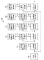
<パターン認識装置100の構成>
パターン認識装置100は、上記図1に示すように、信号入力部130、1次特徴検出部101、1次特徴検出フィルタ設定部111、2次特徴検出部102、2次特徴検出モデル設定部112、2次特徴基準モデル保持部122、3次特徴検出部103、3次特徴検出モデル設定部113、3次特徴基準モデル保持部123、4次特徴検出部104、4次特徴検出モデル設定部114、4次特徴基準モデル保持部124、パターン確認部105、確認パターン設定部115、及び基準確認パターン保持部125を備えている。
【0033】
信号入力部130は、画像信号や音声信号等の処理対象となる信号(ここでは、対象画像の信号)を入力する。
【0034】
1次特徴検出部101は、信号入力部130から入力された信号に対して、1次の特徴を検出するための処理を施し、この処理結果(1次特徴検出結果)を2次特徴検出部102に供給すると共に、当該1次特徴検出結果及びそのパラメータを2次特徴検出モデル設定部112に供給する。
【0035】
このとき、1次特徴検出フィルタ設定部111は、1次特徴検出部101で1次特徴を検出するためのフィルタ特性又はパラメータを設定する。
【0036】
2次特徴検出部102は、1次特徴検出部101からの1次特徴検出結果に対して、2次特徴検出モデル設定部112により設定された検出モデルを用いて、2次の特徴を検出する処理を施し、この処理結果(2次特徴検出結果)を3次特徴検出部103に供給すると共に、当該2次特徴検出結果及びそのパラメータを3次特徴検出モデル設定部113に供給する。
【0037】
このとき、2次特徴検出モデル設定部112は、2次特徴検出部102で2次特徴を検出する際に使用する、1次特徴それぞれの位置関係を示すモデルを、2次特徴基準モデル保持部122に保持された基準モデル、1次特徴検出部101からの1次特徴検出結果、及びそのパラメータを用いて設定する。
2次特徴基準モデル保持部122は、2次特徴検出モデル設定部112で設定する検出モデルの基準モデルを保持する。
【0038】
3次特徴検出部103は、2次特徴検出部102からの2次特徴検出結果に対して、3次特徴検出モデル設定部113により設定された検出モデルを用いて、3次の特徴を検出する処理を施し、この処理結果(3次特徴検出結果)を4次特徴検出部104に供給すると共に、当該3次特徴検出結果及びそのパラメータを4次特徴検出モデル設定部114に供給する。
【0039】
このとき、3次特徴検出モデル設定部113は、3次特徴検出部103で3次特徴を検出する際に使用する、2次特徴それぞれの位置関係を示すモデルを、3次特徴基準モデル保持部123に保持された基準モデル、及び2次特徴検出部102からの2次特徴検出結果及びそのパラメータとを用いて設定する。
3次特徴基準モデル保持部123は、3次特徴検出モデル設定部113で設定する検出モデルの基準モデルを保持する。
【0040】
4次特徴検出部104は、3次特徴検出部103からの3次特徴検出結果に対して、4次特徴検出モデル設定部114により設定された検出モデルを用いて、4次の特徴を検出する処理を施し、この処理結果(4次特徴検出結果)をパターン確認部105に供給すると共に、当該4次特徴検出結果及びそのパラメータを確認パターン設定部115に供給する。
【0041】
このとき、4次特徴検出モデル設定部114は、4次特徴検出部104で4次特徴を検出する際に使用する、3次特徴それぞれの位置関係を示すモデルを、4次特徴基準モデル保持部124に保持された基準モデル、及び3次特徴検出部103からの3次特徴検出結果及びそのパラメータとを用いて設定する。
4次特徴基準モデル保持部124は、4次特徴検出モデル設定部114で設定する検出モデルの基準モデルを保持する。
【0042】
パターン確認部105は、信号入力部130により入力された信号中に、確認パターン設定部115で設定された確認パターンが存在するか否かを確認する。
確認パターン設定部115は、基準確認パターン保持部125に保持された基準パターン、4次特徴検出部104からの4次特徴検出結果、及びそのパラメータを使用して、パターン確認部105で使用する確認パターンを設定する。
基準確認パターン保持部125は、確認パターン設定部115で設定する確認パターンの基準パターンを保持する。
【0043】
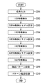
<パターン認識装置100の動作>
図2は、パターン認識装置100の動作をフローチャートにより示したものである。
【0044】
尚、ここではパターン認識処理の一例として、信号入力130からは画像信号が入力され、その画像中の顔領域を検出するものとする。
【0045】
ステップ201:
信号入力部130は、処理対象信号として画像信号を入力する。
【0046】
ステップS202:
1次特徴検出部101は、例えば、1次特徴検出フィルタ設定部111により設定されたフィルタを用いて、信号入力部130により入力された画像信号から構成される画像(対象画像)の各位置で1次特徴を検出する。
【0047】
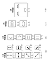
具体的には例えば、図3(a)に示すように、1次特徴検出部101は、対象画像において、縦特徴大(1−1−1)、横特徴大(1−2−1)、右上がり斜め特徴大(1−3−1)、右下がり斜め特徴大(1−4−1)、縦特徴小(1−1−2)、横特徴小(1−2−2)、右上がり斜め特徴小(1−3−2)、及び右下がり斜め特徴小(1−4−2)等の異なる方向及び異なるサイズの特徴を検出し、この検出結果(1次特徴検出結果)を、各特徴毎に対象画像と同等の大きさの検出結果画像という形で出力する。
この結果、ここでは8種類の1次特徴の検出結果画像が得られることになる。これにより、各特徴の検出結果画像の各位置の値を参照することで、対象画像の該当する位置に各特徴が存在するか否かを判断できる。
【0048】
尚、1次特徴検出部101で使用するフィルタは、最初から複数用意するようにしてもよいし、或いは、方向やサイズをパラメータとして、1次特徴検出フィルタ設定部111で作成するようにしてもよい。
また、上記図3(b)〜(d)に示すように、後述する処理で検出する2次特徴は、右空きV字特徴(2−1)、左空きV字特徴(2−2)、水平平行線特徴(2−3)、及び垂直平行線特徴(2−4)であり、3次特徴は、眼特徴(3−1)及び口特徴(3−2)であり、4次特徴は、顔特徴(4−1)であるものとする。
【0049】
ステップS203:
2次特徴検出モデル設定部112は、2次特徴検出部102で2次特徴を検出するためのモデルを設定する。
【0050】
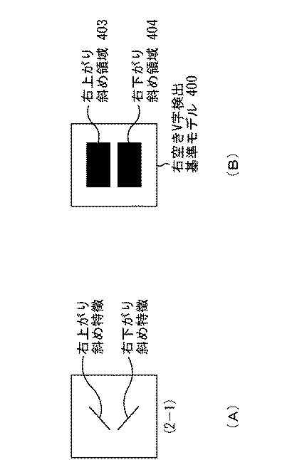
具体的には例えば、まず、上記図3(b)に示す右空きV字特徴(2−1)を検出するための検出モデルの設定を一例として挙げて考えるものとする。
右空きV字特徴(2−1)は、例えば、図4(A)に示すように、1次特徴である右上がり斜め特徴が上部に、右下がり斜め特徴が下部に存在している。すなわち、右空きV字特徴を検出するためには、ステップS202で求めた1次特徴検出の結果を利用して、上部に右上がり斜め特徴が存在し、下部に右下がり斜め特徴が存在する位置を求めればよく、その位置に、右空きV字特徴(2−1)が存在することになる。
このように、複数種類の1次特徴を組み合わせて、2次特徴を検出することができる。
【0051】
しかしながら、対象画像中に存在する顔のサイズは固定サイズではなく、また、個人によって眼や口の大きさが異なり、さらに、眼や口は開閉動作をするため、
右空きV字の大きさも変化する。
【0052】
そこで、本実施の形態では、上記図4(B)に示すような、右空きV字検出基準モデル400を用いる。
右空きV字検出基準モデル400において、403は右上がり斜め領域、404は右下がり斜め領域である。右上がり斜め領域403に対して、ステップS202で求めた1次特徴のうち、右上がり斜め特徴大、若しくは右上がり斜め特徴小のみが存在し、また、右下がり斜め領域404に対して、右下がり斜め特徴大、若しくは右下がり斜め特徴小のみが存在する場合に、その位置に右空きV次特徴(2−1)が存在するとする。このような構成することで、右空きV字について、ある程度の大きさや形状の変化に対して、頑健な処理を施すことができる。
【0053】
しかしながら、例えば、図5(A)及び(B)に示すように、大きさがかなり異なる右空きV字特徴の検出のためには、同じV字検出基準モデル400を使用しても検出が困難である。
【0054】
もちろん、上記図5(A)及び(B)に示すような、大きさがかなり異なる右空きV字特徴を同一のV字基準モデル400を用いて検出するために、例えば、図4(B)に示す右空きV字検出基準モデル400を非常に大きく設定し、その結果右上がり斜め領域403や右下がり斜め領域404を非常に広く取るようにすれば、大小のサイズの異なる右空きV字特徴の検出は可能である。
【0055】
しかしながら、各1次特徴の探索範囲が大きくなるため、例えば、右上がり斜め特徴のサイズは大であり、右下がり斜め特徴のサイズは小であり、さらに、それらの位置も大きくずれている、などという誤検出が起こりやすい。
【0056】
すなわち、右空きV字特徴であれば、右上がり斜め特徴も、右下がり斜め特徴も、それぞれ右空きV字特徴の1構成要素であり、これらの大きさは略同じであり、且つこれらは近傍に存在しており、右空きV字特徴のサイズが大きければ、右上がり斜め特徴のサイズも、右下がり斜め特徴のサイズも、大きくなる。
【0057】
したがって、2次特徴を検出するための基準モデルのサイズは、ステップS202で検出された1次特徴のサイズに合わせて適したものにする。
【0058】
また、1次特徴である、右上がり斜め特徴や右下がり斜め特徴に関しても、常に同じフィルタサイズでの検出は困難である。
【0059】
そこで、上記図5(A)に示すように、対象画像における顔のサイズが小さい場合、1次特徴を小さいサイズのフィルタで検出し、同図5(B)に示すように、対象画像における顔のサイズが大きい場合、1次特徴を大きいサイズのフィルタで検出し、上述したように2次特徴である右空きV字特徴を検出するモデルのサイズをも、1次特徴を検出したフィルタのサイズに依存して変更する。
【0060】
上述のように、本ステップS203では、1次特徴を検出したフィルタのサイズをパラメータとして、各2次特徴の検出のためのモデルを拡大或いは縮小して、各2次特徴を検出するための2次特徴の検出のためのモデルを設定する。
【0061】
上記図5(C)は、顔サイズが小さい場合の右空きV字検出用のモデルを示し、同図(D)は、顔サイズが大きい場合の右空きV字検出用のモデルを示したものである。
これらのモデルは、上記図4(B)に示した右空きV次検出基準モデル400を、それぞれ異なる倍率でサイズ変更したものである。
【0062】
もちろん、1次特徴を検出するために複数のサイズのフィルタを用意し、該当するサイズに合わせて複数の処理チャネルを用意し、それぞれのサイズの2次特徴、さらに3次特徴、…を、それぞれの処理チャネルで検出する方法は有効である。
ただし、対象画像中の顔のサイズの変動が大きい場合、各顔サイズに合わせた処理チャネルを用意すると、処理チャネルの数が多くなる。すなわち、処理コスト量が多くなる。
【0063】
そこで、本実施の形態では、2次特徴検出以降の特徴検出においては、検出モデルのサイズを、前段の階層の検出結果に応じて変更することで、上記の問題を解決している。
【0064】
尚、上記図4(B)に示したような、右空きV字検出基準モデル400、右上がり斜め領域403、及び右下がり斜め領域404は、予め検出すべき特徴に合わせて設定され、2次特徴基準モデル保持部122に保持されているものとする。
【0065】
また、上記図3に示したような各特徴はそれぞれ、前ステップ処理で検出された特徴の組み合わせで検出が可能である。
例えば、2次特徴に関しては、左空きV字特徴は右下がり斜め特徴及び右上がり斜め特徴から検出可能であり、水平平行線特徴は横特徴から検出可能であり、垂直平行線特徴は縦特徴から検出可能である。また、3次特徴に関しては、眼特徴は右空きV字特徴、左空きV字特徴、水平平行線特徴、及び垂直平行線特徴から検出可能であり、口特徴は右空きV字特徴、左空きV字特徴、及び水平平行線特徴から検出可能であり、4次特徴に関しては、顔特徴は眼特徴と口特徴から検出可能である。
【0066】
ステップS204:
2次特徴検出部102は、ステップS203で設定された2次特徴検出モデルを用いて、対象画像の2次特徴を検出する。
【0067】
具体的には例えば、まず、2次特徴の検出は、2次特徴を構成する各1次特徴の値を用いて行うが、例えば、各1次特徴の値が、任意のしきい値以上であるか否かで判断する。
【0068】
例えば、右空きV字検出モデルを用いて、所定の位置の2次特徴の右空きV字特徴を検出する場合で、右上がり斜め領域中に存在する各右上がり斜め特徴の値の最大値がしきい値より高く、且つ右下がり斜め領域中に存在する各右下がり斜め特徴の値の最大値がしきい値より高い場合、その位置に右空きV字特徴が存在するものとする。そして、その位置の値を、それら最大値の平均とする。逆に、各1次特徴の値がしきい値より低い場合、その位置には2次特徴が存在しないとして、その位置の値を“0”とする。
【0069】
上述のようにして求めた2次特徴検出結果は、各2次特徴毎に、対象画像と同等の大きさの検出結果画像という形で出力される。
すなわち、上記図3(b)に示すような2次特徴であれば、4種類の2次特徴検出結果の画像が得られることになる。これらの検出結果画像の各位置の値を参照することで、対象画像の該当する位置に各2次特徴が存在するか否かを判断できる。
【0070】
ところで、本ステップS204の処理では、2次特徴検出モデルの各領域で1次特徴を検出するのではない、ということに注意する必要がある。
【0071】
すなわち、例えば、2次特徴の1つである右空きV字特徴の検出では、右上がり斜め領域と右下がり斜め領域でそれぞれ、1次特徴である右上がり斜め特徴と右下がり斜め特徴を検出するのではない。これらの1次特徴の検出はステップS202で終了しており、したがって、本ステップS204では、これら領域に各1次特徴が存在するか否かを、しきい値を使用して判断している。そして、この結果、複数の1次特徴が、それぞれの領域に存在すると判断した場合に、その位置に2次特徴が存在するとする処理を実行する。このような特徴検出の処理方法は、次の3次特徴及び4次特徴に関しても同様である。
【0072】
また、本ステップS204の処理では、次の3次特徴検出モデルを設定するために使用するパラメータを求める。
例えば、図6に示すように、右空きV字特徴の検出と同時に、右上がり斜め特徴の最大値を示した点と、右下がり斜め特徴の最大値を示した点との距離をパラメータとして求めておく。そして、このパラメータを、各2次特徴検出結果と共に出力する。
【0073】
ステップS205:
3次特徴検出モデル設定部113は、3次特徴検出部103で3次特徴を検出する際に使用する、2次特徴それぞれの位置関係を示すモデルを、3次特徴基準モデル保持部123に保持された基準モデル、及び2次特徴検出部102からの2次特徴検出結果及びそのパラメータとを用いて設定する。
【0074】
具体的には例えば、ここでは説明の簡単のため、上記図3(c)に示すような眼特徴(3−1)を検出するための検出モデルの設定を考える。
図7は、眼を検出するための眼検出基準モデル700の一例を示したものである。眼検出基準モデル700では、2次特徴量である、右空きV字特徴(上記図3(b)の(2−1)参照)の存在する右空きV字領域701が左側に、左空きV字特徴(上記図3(b)の(2−2)参照)の存在する左空きV字領域702が右側に、そして水平平行線特徴(上記図3(b)の(2−3)参照)の存在する水平平行線領域703及び垂直平行線特徴(上記図3(b)の(2−4)参照)の存在する垂直平行線領域704が、これらV字特徴の中間に存在している。
【0075】
本ステップS205においても、ステップS203と同様に、サイズ変動に対応するために、この基準モデルを拡大或いは縮小して3次特徴を検出するのに適した3次特徴検出モデルを設定する。当該基準モデルの拡大或いは縮小に使用するのが、ステップS204で求めたパラメータである。
【0076】
例えば、右空きV字エッジを検出する際に求めた右上がり斜め特徴と右下がり斜め特徴の最大値を示す位置間の距離は、眼の大きさに依存する。そこで、この距離をパラメータとして、眼の基準モデルを基に眼特徴検出モデルを設定する。
【0077】
上述のようにして、各3次特徴に対して、各基準モデルを基に、2次特徴のパラメータを用いて各位置に応じた検出モデルを設定する。
すなわち、例えば、図8(A)に示すように、サイズが異なる(すなわち、眼のサイズが異なる)顔が対象画像中に存在する場合、上述したように2次特徴である右空きV字特徴の大きさをパラメータとして、同図(B)に示すように、各位置に適した眼特徴検出モデルを設定する。
【0078】
上記図8(B)では、眼特徴検出モデル801は、その位置の2次特徴のパラメータ値から求めた大きさとなり、また、眼特徴検出モデル802の位置の2次特徴のパラメータ値から求めた大きさになることを概念的に示している。
【0079】
ステップS206:
3次特徴検出部103は、ステップS205で設定された3次特徴検出モデルを用いて3次特徴を検出する。
ここでの各3次特徴の検出方法は、ステップS204と同様の方法であるため、その詳細な説明は省略する。また、パラメータに関しては、例えば、眼の検出でる場合、最大値を示した右空きV字特徴と左空きV字特徴間の距離(眼の横幅に対応した距離)を求め、これをパラメータとする。
【0080】
ステップS207:
4次特徴検出モデル設定部114は、4次特徴検出部104で4次特徴を検出する際に使用する、3次特徴それぞれの位置関係を示すモデルを、4次特徴基準モデル保持部124に保持された基準モデル、及び3次特徴検出部103からの3次特徴検出結果及びそのパラメータとを用いて設定する。
【0081】
具体的には例えば、顔特徴の検出の場合、顔のサイズと眼の横幅には一般的に関連があるため、上記図3(d)に示すような顔特徴(4−1)の基準モデルに対して、ステップS206で得られた、眼の横幅を示すパラメータを用いて、当該顔の基準モデルを基に、顔特徴検出モデルを設定する。
【0082】
ステップS208:
4次特徴検出部104は、ステップS207で設定された4次特徴検出モデルを用いて、4次特徴を検出する。
ここでの検出方法は、ステップS204及びS206と同様の方法であるため、その詳細な説明は省略する。また、パラメータに関しては、例えば、顔特徴の検出の場合、両眼と口の位置をパラメータとする。このパラメータは、次のステップS209で使用される。
【0083】
ステップS209:
確認パターン設定部115は、基準確認パターン保持部125に保持された基準パターン、4次特徴検出部104からの4次特徴検出結果、及びそのパラメータを使用して、パターン確認部105で使用する確認パターンを設定する。
【0084】
具体的には、まず、ステップS201〜ステップS208の処理で4次特徴検出を行うが、対象画像中の背景において、4次特徴を構成する複数の3次特徴に似た領域が存在し、かつそれらの位置関係も似ている場合、4次特徴検出で誤検出を行う可能性がある。
【0085】
例えば、顔の検出の場合、対象画像中の背景において、それぞれ両眼及び口と似た領域が存在し、また、これらの位置関係も似ている場合、顔特徴の検出で誤検出をする可能性がある。
【0086】
そこで、検出すべきパターンの一般的な基準パターンを用意し、このパターンの大きさや形状を、ステップS208で求めたパラメータを基に修正することで、確認パターンを求め、この確認パターンを用いて、最終的に検出すべきパターンが対象画像中に存在するか否かを判断する。
【0087】
ここでは一例として、顔を検出パターンとしているため、顔の一般的な基準パターンを用意し、この基準パターンを修正することで、顔確認パターンを求め、この顔確認パターンを使用して、顔パターンが対象画像中に存在するかを判断する。
【0088】
このため、本ステップS209では、先ず、基準パターンを基に、ステップS208で求めたパラメータを用いて、確認パターンを設定する。すなわち、顔パターンの設定においては、顔の基準パターンを基に、ステップS206で求めた両眼と口の位置を示すパラメータを用いて、顔確認パターンを設定する。
【0089】
図9(A)及び(B)は、確認パターンの一例を示したものである。
上記図9(A)は、顔基準パターンを示したものであり、この顔基準パターンは、例えば、複数の顔を用意し、これらの大きさを正規化した後で輝度値の平均を取ったものである。
上記図9(A)の顔基準パターンに対して、ステップS208で求められたパラメータ、すなわち両眼の位置及び口の位置を使用して、同図(B)に示すように、サイズや回転の変換を行なう。具体的には例えば、両眼間の距離や、両眼間の中点と口の距離を用いて、サイズの変換を行ない、また、両眼間の傾きを用いて、回転変換を行なうことで、顔確認パターンを設定する。
【0090】
尚、確認パターンの設定方法としては、上述した方法に限られることはなく、例えば、サイズや回転量が異なった複数の基準パターンを用意しておき、これらの基準パターンの中から1つを、ステップS206のパラメータを用いて選択するようにしてもよい。或いは、パラメータを使用して、上記複数の基準パターンをモーフィングの技術等により合成して設定するようにしてもよい。
【0091】
ステップS210:
パターン確認部105は、ステップS209で設定された確認パターンを用いて、対象画像から検出パターンを求める。
【0092】
具体的には例えば、対象画像において、ステップS208で4次特徴が検出された位置で、ステップS209で求めた確認パターンと、対象画像中の該当する位置の部分領域との相関を求め、その値が任意のしきい値を越えた場合に、その位置に検出パターンが存在するものとする。
【0093】
上記説明したように、本実施の形態では、各特徴を検出するための基準モデルを用意し、前段の特徴の検出結果から求めたパラメータを用いて、基準モデルを基に検出モデルを設定するように構成したので、各特徴の検出精度が向上し、最終的に検出するパターンの検出精度が向上する、という効果が得られる。また、最後の確認処理として、平均パターンとの相関を見る際に、それまでに求めた各特徴の位置に応じて、その平均パターンに対して、回転やサイズの変更等の変形を行なうことで、確認精度が向上する、という効果が得られる。
【0094】
<パターン認識装置100の撮像装置1000>
ここでは、上記図1に示したパターン認識(検出)装置100の機能を、例えば、図10に示すような撮像装置1000に搭載させることで、特定被写体へのフォーカシングや、特定被写体の色補正、或いは露出制御を行う場合について説明する。
【0095】
まず、撮像装置1000は、上記図10に示すように、撮影レンズ及びズーム撮影用駆動制御機構を含む結像光学系1002、CCD(又はCMOS)イメージセンサー1003、撮像パラメータの計測部1004、映像信号処理回路1005、記憶部1006、撮像動作の制御や撮像条件の制御等の制御用信号を発生する制御信号発生部1007、EVF等のファインダーを兼ねた表示ディスプレイ1008、ストロボ発光部1009、及び記録媒体1010等を含むと共に、更に、上記図1に示したパターン認識装置100の機能を有する被写体検出(認識)部1011を含む構成としている。
【0096】
上述のような撮像装置1000では、特に、被写体検出(認識)部1011は、例えば、撮影して得られた映像中から、人物の顔画像を検出(存在位置、サイズの検出)する。
【0097】
同制御信号発生部1007は、被写体検出(認識)部1011での検出結果(人物の位置及びサイズ情報)を受け取ると、撮像パラメータ計測部1004の出力に基づき、当該人物に対するピント制御、露出条件制御、及びホワイトバランス制御等を最適に行うための制御信号を発生する。
【0098】
上述のように、上記図1のパターン検出(認識)装置100の機能を、撮像装置1000に用いることで、撮影して得られた映像中の人物検出と、これに基づく撮影の最適制御を行うことができる。
【0099】
尚、上記図10の撮影装置1000では、上記図1のパターン検出装置100の機能を被写体検出(認識)部1011として備える構成としたが、これに限られることはなく、例えば、パターン検出装置100のアルゴリズムをプログラムとして撮影装置1000に実装させ、この撮影装置1000に搭載したCPU(不図示)で当該プログラムを実行するように構成してもよい。このような構成は、以下に説明する第2の実施の形態及び第3の実施の形態でも同様に実施可能である。
【0100】
また、本実施の形態では、対象画像から検出すべきパターンの特徴を4階層に分けて、1次特徴〜4次特徴を順に検出し、最後に検出すべきパターンを確認するように構成したが、この4階層に限られることはなく、3階層や5階層等の任意の階層を適用可能である。これは、以下に説明する第2の実施の形態及び第3の実施の形態でも同様に実施可能である。
【0101】
また、本実施の形態では一例として、顔パターンを検出パターンとして、対象画像から顔領域を求めるものとしたが、本発明は、顔検出のみに限定されるわけではない。
例えば、図11(A)に示すような“24”という数字列を対象画像中から検出することも可能である。
【0102】
上記の数字列検出の場合、上記図11(B)に示すように、“2”は、横方向線分と右斜め下方向線分からなる2次特徴(上部特徴)と、縦方向線分と右斜め上方向線分からなる2次特徴(中間部特徴)と、右斜め上方向線分と横方向線分からなる2次特徴(下部特徴)とから構成され、さらに、これらの2次特徴は、上記図3(a)に示したような1次特徴から構成されている。
【0103】
したがって、先ず、対象画像から1次特徴を検出し、当該1次特徴の検出結果から2次特徴を検出し、そして、当該2次特徴検出結果を用いて、3次特徴としての“2”を検出する。これと同様に“4”に関しても、2次特徴検出結果から3次特徴として検出する。
次に、“2”と“4”の3次特徴検出結果から、4次特徴として“24”を求める。
そして、3次特徴として検出した“2”と“4”の位置関係をパラメータとして、“24”を示す数字列の基準パターンを基に、当該パラメータを用いて“24”の確認パターンを設定し、最終的に“24”を示す数字列を検出する。
【0104】
[第2の実施の形態]
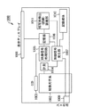
本発明は、例えば、図12に示すような情報処理装置1200に適用される。
本実施の形態の情報処理装置1200は、特に、上記図1に示したパターン認識装置100の機能を有するものである。
【0105】
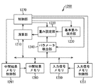
<情報処理装置1200の構成>
情報処理装置1200は、上記図12に示すように、制御部1270、演算部1210、重み設定部1220、基準重み保持部1230、パラメータ検出部1240、入力信号メモリ1250、入力信号メモリ制御部1251、中間結果メモリ1260、及び中間結果メモリ制御部1261を含む構成としている。
【0106】
上述のような情報処理装置1200において、まず、制御部1270は、情報処理装置1200全体の動作制御を司る。
特に、制御部1270は、演算部1210、重み設定部1220、基準重み保持部1230、パラメータ検出部1240、入力信号メモリ制御部1251、及び中間結果メモリ制御部1261を制御することで、パターン認識動作を実施する。
【0107】
演算部1210は、入力信号メモリ1250又は中間結果メモリ1260からのデータと、重み設定部1220からの重みデータとを用いて、これらの積和演算及びロジスティック関数等による非線形演算を行ない、その結果を中間結果メモリ1260に保持する。
【0108】
重み設定部1220は、基準重み保持部1230からの基準重みデータを基に、パラメータ検出部1240からのパラメータを用いて、重みデータを設定し、その重みデータを演算部1210に供給する。
【0109】
基準重み保持部1230は、入力信号中の各特徴を検出するための基準となる基準重みデータを、各特徴それぞれに対して保持しており、その基準重みデータを重み設定部1220に供給する。
【0110】
パラメータ検出部1240は、重み設定部1220で重みデータを設定する際に使用するパラメータを、中間結果メモリ1260のデータを用いて検出し、当該パラメータを重み設定部1220に供給する。
【0111】
入力信号メモリ1250は、画像信号や音声信号等の処理対象となる入力信号を保持する。
入力信号メモリ制御部1251は、入力信号を入力信号メモリ1250に保持する際、また、入力信号メモリ1250に保持されている入力信号を演算部1210に供給する際に、入力信号メモリ1250を制御する。
【0112】
中間結果メモリ1260は、演算処理部1210で得られた演算結果を保持する。
中間結果メモリ制御部1261は、演算部1210からの演算結果を中間結果メモリ1260に保持する際、また、中間結果メモリに保持されている中間結果を演算部1210やパラメータ検出部1240に供給する際に、中間結果メモリ1260を制御する。
【0113】
<情報処理装置1200の動作>
ここでは情報処理装置1200の動作の一例として、並列階層処理により画像認識を行う神経回路網を形成した場合の動作について説明する。すなわち、第1の実施の形態と同様に、処理対象となる入力信号を画像信号とする。
【0114】
まず、図13を参照して、神経回路網の処理内容を詳細に説明する。
神経回路網は、入力信号中の局所領域において、対象又は幾何学的特徴等の認識(検出)に関与する情報を階層的に扱うものであり、その基本構造は、所謂Convolutionalネットワーク構造(LeCun, Y. and Bengio, Y., 1995, "ConvolutionalNetworks for Images Speech, and Time Series" in Handbook of Brain Theory and Neural Networks (M. Arbib, Ed.), MIT Press, pp.255-258)である。最終層(最上位層)からの出力は、認識結果としての認識された対象のカテゴリ、及びその入力データ上の位置情報である。
【0115】
上記図13において、データ入力層1301は、CMOSセンサ或いはCCD素子等の光電変換素子からの局所領域データを入力する層である。
【0116】
最初の特徴検出層1302(1,0)は、データ入力層1301から入力された画像パターンの局所的な低次の特徴(特定方向成分や特定空間周波数成分等の幾何学的特徴の他、色成分特徴等を含む特徴でもよい)を全画面の各位置を中心として、局所領域(或いは、全画面にわたる所定のサンプリング点の各点を中心とする局所領域)において、同一箇所で複数のスケールレベル又は解像度で複数の特徴カテゴリの数のみ検出する。
【0117】
特徴統合層1303(2,0)は、所定の受容野構造(以下、「受容野」とは、直前の層の出力素子との結合範囲を意味し、「受容野構造」とは、その結合荷重の分布を意味する)を有し、特徴検出層1302(1,0)からの同一受容野内にある複数のニューロン素子出力の統合(局所平均化や最大出力検出等によるサブサンプリング等の演算による統合)を行う。
【0118】
上記の統合処理は、特徴検出層1302(1,0)からの出力を空間的にぼかすことで、位置ずれや変形等を許容する役割を有する。また、特徴統合層内のニューロンの各受容野は、同一層内のニューロン間で共通の構造を有している。
【0119】
尚、一般的に特徴検出層内のニューロンの各受容野も同一層内のニューロン間で共通の構造を有しているが、その受容野構造をサイズに関して、前段のニューロンの出力結果(検出結果)に応じて変更するというのが、本実施の形態の主旨である。
【0120】
後続の層である各特徴検出層1302((1,1)、(1,2)、…、(1,M))及び各特徴統合層1303((2,1)、(2,2)、…、(2,M))は、上述した各層と同様に、前者((1,1)、…)は、各特徴検出モジュールにおいて複数の異なる特徴の検出を行ない、後者((2,1)、…)は、前段の特徴検出層からの複数特徴に関する検出結果の統合を行なう。
【0121】
但し、前者の特徴検出層は、同一チャネルに属する前段の特徴統合層の細胞素子出力を受けるように結合(配線)されている。特徴統合層で行う処理であるサブサンプリングは、同一特徴カテゴリの特徴検出細胞集団からの局所的な領域(当該特徴統合層ニューロンの局所受容野)からの出力についての平均化等を行なうものである。
【0122】
図14は、情報処理装置1200の動作の具体例として、第1の実施の形態と同様に、対象画像から顔パターンを認識する場合の動作を、フローチャートにより示したものである。
【0123】
ステップS1401:
入力信号メモリ制御部1251は、制御部1270により入力された信号(ここでは画像信号)を入力信号メモリ1250に入力する。
本ステップS1401が、上記図13に示したデータ入力層1301に対応する。
【0124】
ステップS1402:
重み設定部1220は、例えば、基準重み保持部1230に保持されている、上記図3(a)に示したような1次特徴の検出重みデータ(各方向や各サイズのエッジ抽出を行なうための重みデータ)を演算部1210に対して設定する。
【0125】
尚、サイズや方向をパラメータとしては、1次特徴検出重みデータを重み設定部1220で生成するようにしてもよい。
また、次の2次特徴、3次特徴、及び4次特徴に関しても、例えば、第1の実施の形態で述べた特徴と同様のものを使用することが可能である。
【0126】
ステップS1403:
演算部1210は、1次特徴を検出する。
すなわち、本ステップS1403での1次特徴検出は、上記図13に示した特徴検出層1302(1,0)の処理に対応し、演算部1210は、それぞれの特徴fの検出モジュール1304に相当する処理を実行する。
【0127】
具体的には、ステップS1402で設定された各1次特徴検出重みデータは、各特徴fを検出する受容野1305の構造に相当し、演算部1210は、入力画像メモリ1250から画像信号を取得し、当該画像信号の各位置の局所領域(受容野1305に対応する領域)と、各1次特徴検出重みデータとの積和演算を実行する。
【0128】
ここで、演算処理部1210で実行される特徴検出層ニューロンの入出力特性の一例を、下記の式(1)で示す。すなわち、第L段目の第k番目の特徴を検出する細胞面の位置nにあるニューロンの出力uSL(n,k)は、
【0129】
【数1】
なる式(1)で表される。
【0131】
上記式(1)において、uCL(n,κ)は、第L段目の特徴統合層の第κ番目の細胞面の位置nにあるニューロンの出力を示す。KCLは、第L段目の特徴統合層の種類の数を示す。wL(v,κ,k)は、第L段目の特徴検出細胞層の第k番目の細胞面の位置nにあるニューロンの、第L−1段目の特徴統合層の第κ番目の細胞面の位置n+にあるニューロンからの入力結合である。また、WLは、検出細胞の受容野であり、その大きさは有限である。
【0132】
本ステップS1403の処理は、1次特徴検出であるため、Lは“1”であり、したがって、uCL-1は、データ入力層に相当するため、前段の特徴数は1種類となる。そして、検出する特徴が8種類であるため、8種類の結果が得られることになる。
【0133】
また、上記式(1)において、f()は、積和演算の結果に対しての非線形処理を示す。例えば、この非線形処理には、
【0134】
【数2】
なる式(2)で表されるロジスティック関数を使用する。
【0136】
上記非線形処理された結果は、中間結果メモリ1260に保持される。ここでは、上述したように8種類の特徴を検出しているため、これら全ての特徴の検出結果が、中間結果メモリ1260に保持されることになる。
【0137】
ステップS1404:
重み設定部1220は、基準重み保持手段1230に保持されている1次特徴統合重みデータを演算部1210に対して設定する。
ここでの1次特徴統合重みデータは、ステップS1403で検出された1次特徴の局所的な平均化や最大値の検出等の処理を行なうための重みデータである。
【0138】
ステップS1405:
演算部1210は、中間結果メモリ1260に保持されている各1次特徴の検出結果と、ステップS1404で設定された各1次特徴統合重みデータとの積和演算を行なう処理(各1次特徴の検出結果の統合処理)を実行する。
【0139】
本ステップS1405における処理は、上記図13に示した特徴統合層1303(2,0)の処理に対応し、各特徴fの統合モジュールに相当する処理である。具体的には、特徴検出層1302(1,0)からの同一受容野内に存在する複数のニューロン素子出力の統合(局所平均化、最大出力検出等によるサブサンプリングなどの演算)に相当する。
【0140】
すなわち、演算部1210は、各1次特徴の検出結果毎に、局所領域で平均化や最大値検出等の処理を実行する。例えば、演算部1210は、
【0141】
【数3】
なる式(3)で示される、局所領域での平均化を実行する。
【0143】
上記式(3)において、dL(v)は、第L段目の特徴検出層のニューロンから、第L段目の特徴統合細胞層の細胞面に存在するニューロンへの入力結合であり、|v|に関して単純に減少する関数である。また、DLは、統合細胞の受容野を示し、その大きさは有限である。
【0144】
演算部1210は、上記式(3)による積和演算の結果を中間結果メモリ1260に保持する。
このとき、演算部1210は、上記積和演算の結果に対して、さらに非線形処理を施し、この結果を中間結果メモリ1260に保持するようにしてもよい。
【0145】
本ステップS1405までの処理で、中間結果メモリ1260は、1次特徴検出結果を各特徴毎に局所領域で統合した、各サイズ及び各方向の1次特徴の統合結果を保持していることになる。
【0146】
ステップS1406:
重み設定部1220は、2次特徴検出重みデータを設定する。
ここでの2次特徴検出重みデータは、上述したように、第1の実施の形態で用いた上記図3(b)に示した各2次特徴を検出するための重みデータである。
【0147】
第1の実施の形態においても説明したように、2次特徴以降の各特徴の大きさはそれ以前に求めた特徴の大きさと相関がある。このため、重み設定部1220は、2次特徴以降の各特徴を検出する際に、前段の階層で検出された特徴の大きさに依存して、特徴検出重みデータを設定する。
【0148】
具体的には、先ず、重み設定部1220は、予め設定された、パラメータ検出部1240により各1次特徴を検出した1次特徴検出重みデータが示す受容野サイズを、パラメータとして設定する。
そして、重み設定部1220は、基準重み保持部1230に保持されている基準2次特徴検出重みデータを、上記受容野サイズに関して、先にパラメータ検出部1240により設定したパラメータを用いて修正し、この結果を2次特徴検出重みデータとする。
【0149】
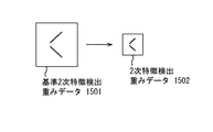
すなわち、例えば、基準2次特徴検出重みデータが、上記図3(a)に示したような1次特徴のサイズが大きい方(受容野サイズが大きい方)に対して設定されているものとすると、重み設定部1220は、受容野サイズが小さい重み係数で検出した1次特徴検出結果に対して、2次特徴を検出する際に、例えば、図15に示すように、2次特徴検出重みデータの受容野サイズを小さくする。
【0150】
ステップS1407:
演算部1210は、2次特徴の検出を行なう。これは、上記図13に示した特徴検出層1302(1,1)の処理に対応する。
【0151】
本ステップS1407での処理自体は、ステップS1403における1次特徴検出処理と同様である。
例えば、演算部1210は、上記式(1)を用いた積和演算、及びその結果に対する非線形演算の処理を実行する。ただし、演算部1210は、ステップS1406で設定された2次特徴検出重みデータ、及び中間結果メモリ1260に保持されている1次特徴の統合結果を、積和演算に使用し、当該演算結果に対して非線形演算を行ない、当該演算結果(2次特徴検出結果)を中間結果メモリ1260に保持する。
【0152】
ステップS1408:
重み設定部1220は、基準重み保持部1230に保持されている2次特徴統合重みデータを演算部1210に対して設定する。
ここでの2次特徴統合重みデータは、ステップS1407で検出した2次特徴結果の局所的な平均化や最大値の検出等の処理を実行するための重みデータである。
【0153】
ステップS1409:
演算部1210は、各2次特徴の検出結果を統合する。これは、上記図13に示した特徴統合層1303(2,1)の処理に対応する。
【0154】
具体的には、演算部1210は、中間結果メモリ1260に保持されている各2次特徴の検出結果と、ステップS1408で設定された各2次特徴統合重みデータとの積和演算を、例えば、上記式(3)に従って実行し、当該積和演算の結果を中間結果メモリ1260に保持する。このとき、演算部1210は、上記積和演算の結果に対して、さらに非線形処理を施し、当該処理結果を中間結果メモリ1260に保持するようにしてもよい。
【0155】
ステップS1410:
重み設定部1220は、3次特徴検出重みデータを演算部1210に対して設定する。
ここでの3次特徴検出重みデータは、上述したように、第1の実施の形態における上記図3(c)で示した各3次特徴を検出するための重みデータである。
【0156】
具体的には、先ず、重み設定部1220は、パラメータ検出部1240で、中間結果メモリ1260に保持されている各1次特徴検出結果及び各2次特徴検出結果から、2次特徴の大きさに基づいた値をパラメータとして設定する。このパラメータとしては、例えば、第1の実施の形態で説明したように、右空きV字特徴の場合、右上がり斜め特徴と右下がり斜め特徴間の垂直距離を使用することができる。
そして、重み設定部1220は、基準重み保持部1230に保持されている基準3次特徴検出重みデータを、その受容野サイズに関して、パラメータ検出部1240で求めたパラメータを用いて修正し、この結果を3次特徴検出重みデータとする。
【0157】
ステップS1411:
演算部1210は、3次特徴検出を行なう。これは、上記図13に示した特徴検出層1302(1,2)の処理に対応する。
【0158】
具体的には、演算部1210は、ステップS1410で設定された3次特徴検出重みデータと、中間結果メモリ1260に保持されている2次特徴の統合結果との積和演算、及びその結果に対する非線形演算を実行し、当該演算結果(3次特徴検出結果)を中間結果メモリ1260に保持する。
【0159】
ステップS1412:
重み設定部1220は、基準重み保持部1230に保持されている3次特徴統合重みデータを演算部1210に対して設定される。
ここでの3次特徴統合重みデータは、ステップS1411で検出した3次特徴結果の局所的な平均化や最大値検出等の処理を行なうための重みデータである。
【0160】
ステップS1413:
演算部1210は、各3次特徴の検出結果を統合する。これは、上記図13に示した特徴統合層1303(2,2)の処理に対応する。
【0161】
具体的には、演算部1210は、中間結果メモリ1260に保持されている各3次特徴の検出結果と、ステップS1412で設定された各3次特徴統合重みデータとの積和演算を実行し、当該積和演算の結果を中間結果メモリ1260に保持する。このとき、演算部1210は、当該積和演算の結果に対して、さらに非線形処理を行い、当該処理結果を中間結果メモリ1260に保持するようにしてもよい。
【0162】
ステップS1414:
重み設定部1220は、4次特徴検出重みデータを演算部1210に対して設定する。
ここでの4次特徴検出重みデータは、上述したように、第1の実施の形態で使用した上記図3(d)に示した各4次特徴を検出するための重みデータである。
【0163】
具体的には、先ず、重み設定部1220は、パラメータ検出部1240で、中間結果メモリ1260に保持されている各2次特徴検出結果及び各3次特徴検出結果から、3次特徴の大きさに基づいた値をパラメータとして設定する。このパラメータとしては、例えば、第1の実施の形態で説明したように、眼特徴の場合、右空きV字特徴と左空きV字特徴間の水平距離を使用することができる。
そして、重み設定部1220は、基準重み保持部1230に保持されている基準4次特徴検出重みデータを、その受容野サイズに関して、パラメータ検出部1240で求めたパラメータを用いて修正し、この結果を4次特徴検出重みデータとする。
【0164】
ステップS1415:
演算部1210は、4次特徴検出を行なう。これは、上記図13に示した特徴検出層1302(1,3)の処理に対応する。
【0165】
具体的には、演算部1210は、ステップS1414で設定された4次特徴検出重みデータと中間結果メモリ1260に保持されている3次特徴の統合結果との積和演算、及びその結果に対する非線形演算を実行し、当該演算結果(4次特徴検出結果)を中間結果メモリ1260に保持する。
【0166】
ステップS1416:
重み設定部1220は、基準重み保持手段1230に保持されている4次特徴統合重みデータを演算部1210に対して設定する。
ここでの4次特徴統合重みデータは、ステップS1415で検出した4次特徴結果の局所的な平均化や最大値の検出等の処理を行なうための重みデータである。
【0167】
ステップS1417:
演算部1210は、4次特徴の検出結果を統合する。これは、上記図13に示した特徴統合層1303(2,3)の処理に対応する。
【0168】
具体的には、演算部1210は、中間結果メモリ1260に保持されている4次特徴の検出結果と、ステップS1416で設定された4次特徴統合重みデータとの積和演算を実行し、当該積和演算の結果を中間結果メモリ1260に保持する。このとき、演算部1210は、当該積和演算の結果に対して、さらに非線形処理を行い、当該処理結果を中間結果メモリ1260に保持するようにしてもよい。
【0169】
ステップS1418:
演算部1210は、パターン確認重みデータを設定する。
【0170】
具体的には、まず、上述したステップS1417までの処理により、4次特徴が検出されるが、第1の実施の形態で説明したように、対象画像(入力画像)中の背景に4次特徴を構成する複数の3次特徴に似た領域があり、また、これらの位置関係をも似ている場合、4次特徴の検出で誤検出する可能性がある。すなわち、例えば、顔の検出の場合、入力画像中の背景に、それぞれ両眼及び口と似た領域が存在し、また、その位置関係をも似ている場合、顔特徴の検出で誤検出する可能性がある。
【0171】
このため、本実施の形態では、検出すべきパターンにおいて典型的なタイプ(サイズや向き等)を検出するための基準パターン確認重みデータを用意し、当該重みデータを修正し、当該修正後のパターン確認重みデータを設定し、当該設定パターン確認重みデータを用いて、最終的に検出すべきパターンが入力画像中に存在するか否かを判断する。
【0172】
ここで一例として、顔を検出パターンとしているので、典型的な顔を検出する基準顔パターン確認重みデータを用意し、これを修正し、当該修正後の顔パターン確認重みデータを設定し、当該設定顔パターン確認重みデータを使用して、顔パターンが入力画像中に存在するかを判断する。
【0173】
したがって、本ステップS1418では、先ず、演算部1210は、パラメータ検出部1240で、中間結果メモリ1260に保持されている各3次特徴検出結果及び4次特徴検出結果から、検出した4次特徴の各位置において、3次特徴検出結果に基づいた値をパラメータとして設定する。このパラメータとしては、例えば、第1の実施の形態で説明したように、顔特徴である場合、眼特徴と口特徴の位置を使用することができる。
そして、演算部1210は、基準重み保持部1230に保持されている基準パターン確認重みデータを、その受容野サイズ及び回転に関して、パラメータ検出部1240で求めたパラメータを用いて修正し、当該修正結果をパターン確認重みデータとする。
【0174】
ステップS1419:
演算部1210は、検出パターンの確認を行なう。
具体的には、演算部1210は、ステップS1418で設定された確認パターン重みデータと、入力信号メモリ1250に保持されている入力信号との積和演算、及びその結果に対する非線形演算を実行し、当該演算結果を中間結果メモリ1260に保持する。この中間結果メモリ1260に保持された結果が、検出すべきパターンの検出最終結果となる。
【0175】
上記説明したように、本実施の形態では、各特徴を検出するための基準重みデータを用意し、前段の検出結果から求めたパラ―メータを用いて、当該基準重みデータを基に、検出重みデータを設定するように構成したので、各特徴の検出精度が向上し、最終的に検出するパターンの検出精度が向上するという効果がある。
【0176】
また、演算部1210では、検出重みデータ又は統合重みデータと、中間結果メモリ1260又は入力信号メモリ1250からのデータとの積和演算及びその結果の非線形変換を行い、当該積和演算に使用する重みデータを、毎回設定するように構成したので、同じ演算部1210を繰り返し使用できるという効果がある。さらに、入力信号と中間結果の両方を保持する構成としているので、最後の確認処理をも容易に行えるという効果がある。
【0177】
尚、本実施の形態では、その一例として、統合処理に使用する統合重みデータに対して、検出結果に応じた設定を行なっていないが、例えば、検出重みデータ同様に、受容野サイズの設定を行なうことも可能である。また、上記図14に示したステップS1416及びS1417の4次特徴に対する統合処理は、省略することも可能である。
【0178】
[第3の実施の形態]
本発明は、例えば、図16に示すような情報処理装置1600に適用される。本実施の形態の情報処理装置1600は、特に、上記図1に示したパターン認識装置100の機能を有するものである。
【0179】
具体的には、まず、情報処理装置1600は、上記図16に示すように、制御部1670、演算部1610、基準重み保持部1630、パラメータ検出部1640、入力信号メモリ1650、入力信号メモリ制御部1651、中間結果メモリ1660、及び中間結果メモリ制御部1661を含む構成としている。
【0180】
ここで、本実施の形態における情報処理装置1600は、基本的には第2の実施の形態における情報処理装置1200(上記図12参照)と同様の機能を有するものであるが、これと異なる点は、重み設定部1220に相当する機能を持たず、パラメータ検出部1640で求めたパラメータを中間結果メモリ制御部1661及び演算部1610に供給するように構成したことにある。
【0181】
すなわち、第2の実施の形態では、前段の処理結果からパラメータを求め、そのパラメータから特徴を検出するための重みデータを設定するように構成したが、本実施の形態では、重みデータとして、基準重み保持手段1630に保持されている基準重みデータをそのまま使用し、替わりに受容野に相当する、中間結果メモリ1660に保持されている前段の検出結果を、補間等を用いてサイズ変更するように構成する。
【0182】
このため、例えば、3次特徴である眼特徴を検出する場合、情報処理装置1600は、図17に示すように、入力画像1700に対する通常の受容野に対して、サイズ変更することで、サイズ変更後局所画像1710を生成し、この変更後局所画像1710と、基準重み保持手段1630に保持されている基準重みデータとの積和演算を実行する。
【0183】
尚、3次特徴を求める場合、中間結果メモリ1660に保持されている2次特徴検出結果を使用するが、上記図17では、説明の簡単のため、入力画像1700の局所画像のサイズ変更を示している。実際には、2次特徴検出結果画像の局所領域をサイズ変更して使用する。
【0184】
以上説明したように、本実施の形態では、前段の検出結果から求めたパラ―メータを用いて、特徴を検出する際に使用する前段の検出結果のサイズを変更して再設定するように構成したので、各特徴の検出精度が向上し、最終的に検出するパターンの検出精度が向上する、という効果を得られる。また、検出結果のサイズを変更は、メモリから読み出す領域の変更と補間処理で良いため、容易に実現できる、という効果をも得られる。
【0185】
尚、第2及び第3の実施の形態における情報処理装置1200,1600の機能を、例えば、第1の実施の形態と同様に、撮像装置に搭載させることも可能である。
【0186】
また、本発明の目的は、第1〜第3の実施の形態のホスト及び端末の機能を実現するソフトウェアのプログラムコードを記録した記録媒体を、システム或いは装置に供給し、そのシステム或いは装置のコンピュータ(又はCPUやMPU)が記録媒体に格納されたプログラムコードを読みだして実行することによっても、達成されることは言うまでもない。
この場合、記録媒体から読み出されたプログラムコード自体が第1〜第3の実施の形態の機能を実現することとなり、そのプログラムコードを記録した記録媒体及び当該プログラムコードは本発明を構成することとなる。
プログラムコードを供給するための記録媒体としては、ROM、フレキシブルディスク、ハードディスク、光ディスク、光磁気ディスク、CD−ROM、CD−R、磁気テープ、不揮発性のメモリカード等を用いることができる。
また、コンピュータが読みだしたプログラムコードを実行することにより、第1〜第3の実施の形態の機能が実現されるだけでなく、そのプログラムコードの指示に基づき、コンピュータ上で稼動しているOS等が実際の処理の一部又は全部を行い、その処理によって第1〜第3の実施の形態の機能が実現される場合も含まれることは言うまでもない。
さらに、記録媒体から読み出されたプログラムコードが、コンピュータに挿入された拡張機能ボードやコンピュータに接続された機能拡張ユニットに備わるメモリに書き込まれた後、そのプログラムコードの指示に基づき、その機能拡張ボードや機能拡張ユニットに備わるCPUなどが実際の処理の一部又は全部を行い、その処理によって第1〜第3の実施の形態の機能が実現される場合も含まれることは言うまでもない。
【0187】
図18は、上記コンピュータの機能1800を示したものである。
コンピュータ機能1800は、上記図18に示すように、CPU1801と、ROM1802と、RAM1803と、キーボード(KB)1809のキーボードコントローラ(KBC)1805と、表示部としてのCRTディスプレイ(CRT)1810のCRTコントローラ(CRTC)1806と、ハードディスク(HD)1811及びフレキシブルディスク(FD)1812のディスクコントローラ(DKC)1807と、ネットワーク1820との接続のためのネットワークインターフェースコントローラ(NIC)1808とが、システムバス1804を介して互いに通信可能に接続された構成としている。
【0188】
CPU1801は、ROM1802或いはHD1811に記録されたソフトウェア、或いはFD1812より供給されるソフトウェアを実行することで、システムバス1804に接続された各構成部を総括的に制御する。
すなわち、CPU1801は、所定の処理シーケンスに従った処理プログラムを、ROM1802、或いはHD1811、或いはFD1812から読み出して実行することで、第1〜第3の実施の形態での動作を実現するための制御を行う。
【0189】
RAM1803は、CPU1801の主メモリ或いはワークエリア等として機能する。
KBC1805は、KB1809や図示していないポインティングデバイス等からの指示入力を制御する。
CRTC1806は、CRT1810の表示を制御する。
DKC1807は、ブートプログラム、種々のアプリケーション、編集ファイル、ユーザファイル、ネットワーク管理プログラム、及び本実施の形態における所定の処理プログラム等を記録するHD1811及びFD1812とのアクセスを制御する。
NIC1808は、ネットワーク1820上の装置或いはシステムと双方向にデータをやりとりする。
【0190】
【発明の効果】
以上説明したように本発明では、入力信号(画像信号等)に含まれる所定パターン(顔パターン等)を構成する複数の特徴(眼や口等)を階層的に検出するにあたり、対象特徴の検出に使用するデータを、対象特徴に対応した基準データ(基準顔データ等)、及び対象特徴の前段の特徴の検出結果に基づいて設定するように構成した。
【0191】
これにより、例えば、同一階層の各特徴の検出処理を独立に行い、次の階層の特徴を検出する際に、その前段の階層の複数の特徴の検出結果から求めたパラメータを用いて、各特徴を検出する際に使用するモデル又は重み等のデータを、適応的に設定できるため、或いは、特徴検出の際に使用する前段の検出結果から求めたパラメータを用いて適応的に再設定できるため、各特徴の検出精度を向上させることができ、入力信号中に、サイズが異なる複数の認識対象が存在する場合であっても、全ての認識対象を、少ない処理コストで検出することができる。
【0192】
また、例えば、最後の確認処理として、確認パターンとの相関を求める際に、これまでに求めた各特徴の位置に応じて、当該確認パターンに対して回転やサイズ変更等の変形(変換)を行なうように構成した場合、確認精度を向上させることができる。
【0193】
また、上記の機能を、例えば、撮像装置に適用するように構成した場合、画像中の顔等の特定領域の色補正や、フォーカスの設定等を容易に行える。
【0194】
よって、本発明によれば、対象信号中に存在する任意の領域を特定の認識対象として検出するにあたり、認識対象が如何なるものであっても、少ない処理コストで効率的に検出できる。
特に、例えば、対象画像中にサイズの異なる複数の認識対象が存在する場合であっても、全ての認識対象を、少ない処理コストで抽出することができ、また、認識対象のパターンではないにも関わらず認識対象のパターンとして誤って検出してしまう誤検出を防ぐことができる。
【図面の簡単な説明】
【図1】第1の実施の形態において、本発明を適用したパターン認識(検出)装置の構成を示すブロック図である。
【図2】上記パターン認識(検出)装置の動作を説明するためのフローチャートである。
【図3】上記パターン認識(検出)装置において、顔領域を検出する際の特徴の一例を説明するための図である。
【図4】上記顔領域検出の際に用いる検出基準データの一例を説明するための図である。
【図5】上記顔領域検出の対象画像の一例を説明するための図である。
【図6】上記顔領域検出の際に用いるパラメータの一例を説明するための図である。
【図7】上記顔領域の眼領域を検出する際の特徴の検出基準モデルの一例を説明するための図である。
【図8】上記眼領域検出の対象画像において、位置による眼特徴の検出モデルの違いを説明するための図である。
【図9】上記顔領域検出の確認パターンの設定を説明するための図である。
【図10】上記パターン認識(検出)装置の機能付き撮像装置の構成を示すブロック図である。
【図11】上記パターン認識(検出)装置の機能による文字列の検出を説明するための図である。
【図12】第2の実施の形態において、本発明を適用した情報処理装置の構成を示すブロック図である。
【図13】上記情報処理装置において、Convolutionalニューラルネットワーク構造を説明するための図である。
【図14】上記情報処理装置の動作を説明するためのフローチャートである。
【図15】上記情報処理装置において、特徴検出重みデータを模式的に説明するための図である。
【図16】第3の実施の形態において、本発明を適用した情報処理装置の構成を示すブロック図である。
【図17】上記情報処理装置の機能を模式的に説明するための図である。
【図18】第1〜第3の実施の形態における装置の機能をコンピュータに実現させるためのプログラムをコンピュータ読み取り可能な記録媒体から読み出して実行する当該コンピュータの構成を示すブロック図である。
【符号の説明】
100 パターン認識(検出)装置
101 1次特徴検出部
102 2次特徴検出部
103 3次特徴検出部
104 4次特徴検出部
105 パターン確認部
111 1次特徴検出フィルタ設定部
112 2次特徴検出モデル設定部
113 3次特徴検出モデル設定部
114 4次特徴検出モデル設定部
115 確認パターン設定部
122 2次特徴基準モデル保持部
123 3次特徴基準モデル保持部
124 4次特徴基準モデル保持部
125 基準確認パターン保持部
130 信号入力部[0001]
TECHNICAL FIELD OF THE INVENTION
The present invention provides, for example, a pattern recognition device, an imaging device, and information used in an apparatus or a system that performs hierarchical operation processing on a target image to perform pattern recognition or detection of a specific subject in the target image. The present invention relates to a processing system, a pattern recognition method, a computer-readable recording medium storing a program for executing the method, and the program.
[0002]
[Prior art]
Conventionally, for example, in the field of image recognition and voice recognition, a recognition processing algorithm specialized for a specific recognition target is executed by computer software or hardware using a dedicated parallel image processing processor, so that the recognition target and the background are recognized. There is known a technique for detecting a recognition target from an image including a character.
[0003]
In particular, as a configuration for detecting a face area existing in a target image as a specific recognition target, for example, Japanese Patent No. 2767814, Japanese Patent Laid-Open No. 9-251534, Japanese Patent Laid-Open No. 9-44676, Japanese Patent No. 2973676, and There is one disclosed in Kaihei 11-283036 and the like.
[0004]
Specifically, first, the configuration described in Japanese Patent Application Laid-Open No. 9-251534 uses a template called a standard face for an input image (target image), searches for a face area in the target image, After that, a person in the target image is authenticated by using a partial template for feature points such as eyes, nostrils, and mouth from the face area.
[0005]
The configuration described in Japanese Patent No. 2767814 and the like obtains an eye and a mouth candidate group from a face image and compares the face candidate group obtained by combining the eye and mouth candidate groups with a previously recorded face structure to obtain an eye in the face image. And the area corresponding to the mouth.
[0006]
The configuration described in Japanese Patent Application Laid-Open No. 9-44676 or the like obtains a plurality of eye, nose, and mouth candidates from a target image, and obtains a positional relationship between these candidates and a feature point prepared in advance. This is for detecting a face area in the target image.
[0007]
In the configuration described in Japanese Patent No. 2973676, when examining the degree of coincidence between the shape data of each face part and the input image, the shape data is changed. Is determined on the basis of the positional relationship of the parts previously obtained.
[0008]
In the configuration described in Japanese Patent Application Laid-Open No. H11-283036 or the like, a region model in which a plurality of determination element acquisition regions are set is moved in an input image (target image), and a determination is made at each point within the determination element acquisition regions. By determining the presence or absence of an element, a face area in the target image is recognized.
[0009]
[Problems to be solved by the invention]
However, the conventional configuration for image recognition (pattern recognition) as described above has the following problems.
[0010]
First, in a conventional configuration described in Japanese Patent Application Laid-Open No. 9-251534 or the like, a face area in a target image is searched by first performing matching of the entire face using a template called a standard face for the target image. Therefore, it is difficult to deal with faces of various sizes and changes in the direction of the face. In order to deal with this, it is necessary to prepare multiple standard faces corresponding to the face size and face direction, and to use each of them to detect, the size of the entire face template increases. Accordingly, the processing cost also increases.
[0011]
In the conventional configuration described in Japanese Patent No. 2767814 and the like, a face candidate group obtained by combining an eye and a mouth candidate group obtained from a face image is collated with a previously recorded face structure, so that eyes in the face image are compared. If the application is to create a portrait from the target image, for example, the number of faces in the target image is usually one or a small number, and the size of the face is somewhat large. It can be considered that most of the area in the target image is a face and the background is small. With such a target image, the number of face candidates is limited even if face candidates are created from all eye and mouth candidate groups. However, when the target image is, for example, an image obtained by photographing with a general camera or video, the size of the face in the target image may be reduced, and the background may be increased accordingly. In such a case, many eye and mouth candidates are erroneously detected in the background, and if face candidates are created from all of the eye and mouth candidate groups, the number of face candidates becomes enormous. Processing costs will increase.
[0012]
In the conventional configuration described in Japanese Patent Application Laid-Open No. 9-44676, a plurality of eye, nose, and mouth candidates are respectively obtained from a target image, and a positional relationship between these candidates and feature points prepared in advance is determined. , The face area in the target image is detected. In this configuration, similarly to the configuration described in Japanese Patent No. 2767814 or the like, if there are many candidates for eyes, nose, and mouth in the background, The processing cost for collating the relationship becomes enormous.
[0013]
In the conventional configuration described in Japanese Patent No. 2973676, the shape data (shape data of the iris, mouth, nose, etc.) of each part of the face is held, and two irises are obtained first, followed by the mouth and nose. When obtaining the like, the search area of the face parts such as the mouth and the nose is limited based on the position of the iris. That is, in the algorithm of the configuration, instead of detecting face parts constituting the face such as the iris (eye), mouth, and nose in parallel, the iris (eye) is detected first, and the detection result is used. Then, face parts such as a mouth and a nose are sequentially detected. Therefore, the configuration is based on the assumption that only one face exists in the target image and the iris is accurately obtained. Therefore, if the detected iris is erroneously detected, the mouth or nose is detected. Etc. cannot be set correctly.
[0014]
In the conventional configuration described in Japanese Patent Application Laid-Open No. H11-283036, an area model in which a plurality of determination element acquisition areas are set is moved in an input image (target image), and each point is moved within the determination element acquisition areas. By recognizing the presence / absence of a determination element, a face region in the target image is recognized. However, in order to correspond to various types of face sizes, it is necessary to prepare region models of different sizes, and If there is no face with a size, a lot of useless processing is executed, which is inefficient.
[0015]
Therefore, the present invention has been made in order to eliminate the above-described drawbacks, and in detecting an arbitrary region existing in a target image as a specific recognition target, regardless of the recognition target, A pattern recognition device, an imaging device, an information processing system, a pattern recognition method, a computer-readable recording medium on which a program for executing the pattern recognition device is recorded, and a program capable of efficiently detecting the processing cost. And
[0016]
Specifically, for example, even when a plurality of recognition targets having different sizes exist in the target image, it is possible to extract all the recognition targets at a small processing cost. Further, it is possible to prevent erroneous detection that is erroneously detected as a pattern to be recognized even though the pattern is not a pattern to be recognized.
[0017]
[Means for Solving the Problems]
For such a purpose, a pattern recognition device for detecting a predetermined pattern included in an input signal according to the present invention includes: a feature detection unit that hierarchically detects a plurality of features of the predetermined pattern; Reference data holding means for holding a plurality of pieces of reference data, and data used for detection of a target feature by the feature detection means are obtained by the reference data held by the reference data holding means, and the feature detection means. Data setting means for setting based on the detection result of the preceding feature of the target feature.
[0018]
Further, according to the present invention, there is provided a pattern recognition device for detecting a predetermined pattern included in an input signal, wherein the pattern recognition device hierarchically detects a plurality of characteristics of the predetermined pattern, and a plurality of standards corresponding to the plurality of characteristics. Reference data holding means for holding data, wherein when detecting a higher-order feature at a predetermined position of the input signal, the feature detector detects an input from a detection result of a previous hierarchy used for the feature detection. It is characterized in that the size of the local region as a range is set based on the detection results of the plurality of features of the preceding hierarchy.
[0019]
Further, according to the present invention, a pattern recognition device that detects a predetermined pattern included in an input signal includes a feature detection unit that hierarchically detects a plurality of features of the predetermined pattern, and a result detected by the feature detection unit. Holding means for holding, and parameter obtaining means for obtaining a parameter based on the detection result held in the holding means, wherein the parameter obtaining means changes the detection result read from the holding means based on the obtained parameter, The feature detection means performs feature detection based on the detection result.
[0020]
Further, according to the present invention, a pattern recognition method for detecting a predetermined pattern included in an input signal includes a feature detection step of hierarchically detecting a plurality of features constituting the predetermined pattern, and a feature detection step. A reference data holding step of holding a plurality of reference data for detecting a plurality of features, respectively, and data used for feature detection in the feature detection step are set based on the reference data held in the reference data holding step. A data setting step, wherein when setting data for detecting a feature in the feature detecting step, the feature detecting step is performed based on the reference data held in the reference data holding step. Using the parameters obtained from the detection result of the preceding feature of the detection target feature obtained by Characterized in that it comprises the step of setting.
[0021]
Further, according to the present invention, a pattern recognition method for detecting a predetermined pattern included in an input signal includes a feature detection step of hierarchically detecting a plurality of features constituting the predetermined pattern; A reference data holding step of holding a plurality of reference data for detecting a plurality of features, respectively, the feature detection step, at a predetermined position of the input signal, when detecting a higher-order feature, Setting a size of a local region as an input range from the detection result of the preceding hierarchy used for the detection using parameters obtained from the detection results of a plurality of features of the preceding hierarchy. .
[0022]
Further, a pattern recognition method for detecting a face pattern included in an input image according to the present invention includes a feature detecting step of hierarchically detecting a plurality of features constituting a face, and a plurality of feature detection steps. A reference data holding step of holding a plurality of reference data for detecting each of the features; an eye holding the reference face data for detecting a typical face pattern by the reference data holding step; And converting the reference face data based on the positional relationship between the mouth and the mouth, and checking the presence or absence of a face pattern in the input image based on the correlation between the converted reference face data and the input image. It is characterized by the following.
[0023]
Further, according to the present invention, a pattern recognition method for detecting a predetermined pattern included in a target signal includes a feature detection step of hierarchically detecting a plurality of features constituting the predetermined pattern; A data setting step of setting data to be used for detecting a feature based on reference data for detecting a plurality of features, wherein the data setting step sets data for detecting a feature. At this time, it is characterized in that the method includes a step of setting based on the reference data and using a parameter obtained from a result of detecting a feature in the preceding stage.
[0024]
Further, according to the pattern recognition method for detecting a predetermined pattern included in an input signal according to the present invention, when a plurality of features constituting the predetermined pattern are detected hierarchically, a predetermined position of the input signal is detected at a predetermined position. When detecting a higher-order feature, the size of a local region as an input range from the detection result of the preceding hierarchy used for detection is determined by a parameter obtained from the detection results of a plurality of features of the preceding hierarchy. It is characterized by including a feature detecting step to be set by using.
[0025]
In addition, a pattern recognition method for detecting a face pattern included in an input image using predetermined reference face data according to the present invention includes a feature detecting step of hierarchically detecting a plurality of features constituting a face. And converting the reference face data based on the positional relationship between the eyes and the mouth obtained in the feature detection step, based on the correlation between the converted reference face data and the input image, And a confirmation step of confirming the presence / absence of a face pattern.
[0026]
According to the present invention, there is provided a program for causing a computer to function as a predetermined means, wherein the predetermined means hierarchically detects a plurality of characteristics of a predetermined pattern included in an input signal; Reference data holding means for holding a plurality of reference data corresponding to the features of the above, data used for detection of the target feature by the feature detection means, reference data held in the reference data holding means, and feature detection Data setting means for setting based on a result of detection of a preceding feature of the target feature obtained by the means.
[0027]
According to the present invention, there is provided a program for causing a computer to function as a predetermined means, wherein the predetermined means hierarchically detects a plurality of characteristics of a predetermined pattern included in an input signal; Reference data holding means for holding a plurality of pieces of reference data corresponding to the characteristics of the input signal, when the characteristic detection means detects a higher-order characteristic at a predetermined position of the input signal, the reference data is used for the characteristic detection. The size of the local area as an input range from the detection result of the previous hierarchy is set based on the detection results of a plurality of features of the previous hierarchy.
[0028]
According to the present invention, there is provided a program for causing a computer to function as a predetermined means, wherein the predetermined means detects a plurality of features of the predetermined pattern in a hierarchical manner, and the feature detection means detects Holding means for holding the obtained result, and parameter obtaining means for obtaining a parameter based on the detection result held by the holding means, wherein the parameter obtaining means reads the detection result read from the holding means based on the obtained parameter. In another feature, the feature detection means performs feature detection based on the detection result.
[0029]
Further, the present invention is characterized in that the program according to any one of claims 21 to 23 is recorded on a computer-readable recording medium.
[0030]
BEST MODE FOR CARRYING OUT THE INVENTION
Hereinafter, embodiments of the present invention will be described with reference to the drawings.
[0031]
[First Embodiment]
The present invention is applied to, for example, a
The
Hereinafter, the configuration and operation of the
[0032]
<Configuration of
As shown in FIG. 1, the
[0033]
The
[0034]
The primary
[0035]
At this time, the primary feature detection
[0036]
The secondary
[0037]
At this time, the secondary feature detection
The secondary feature reference
[0038]
The tertiary
[0039]
At this time, the tertiary feature detection
The tertiary feature reference
[0040]
The quaternary
[0041]
At this time, the quaternary feature detection
The fourth-order feature reference
[0042]
The
The confirmation
The reference check
[0043]
<Operation of
FIG. 2 is a flowchart illustrating the operation of the
[0044]
Here, as an example of the pattern recognition processing, it is assumed that an image signal is input from the
[0045]
Step 201:
The
[0046]
Step S202:
The primary
[0047]
Specifically, for example, as shown in FIG. 3A, the primary
As a result, eight types of primary feature detection result images are obtained here. Thus, by referring to the value of each position of the detection result image of each feature, it can be determined whether each feature exists at the corresponding position of the target image.
[0048]
Note that a plurality of filters used by the primary
As shown in FIGS. 3B to 3D, the secondary features detected in the processing described later include a right empty V-shaped feature (2-1), a left empty V-shaped feature (2-2), A horizontal parallel line feature (2-3) and a vertical parallel line feature (2-4), a tertiary feature is an eye feature (3-1) and a mouth feature (3-2), and a quaternary feature is , Face characteristic (4-1).
[0049]
Step S203:
The secondary feature detection
[0050]
Specifically, for example, the setting of a detection model for detecting the right empty V-shaped feature (2-1) shown in FIG. 3B will be considered as an example.
As shown in FIG. 4A, for example, the right empty V-shaped feature (2-1) includes a primary feature, which is an obliquely right-up feature at the upper portion, and a diagonally down-right feature at the lower portion. That is, in order to detect a right empty V-shaped feature, a position where an upward-sloping diagonal feature exists at the upper part and a lower-right diagonal feature exists at the lower part using the result of the primary characteristic detection obtained in step S202. , And the right empty V-shaped feature (2-1) exists at that position.
In this way, secondary features can be detected by combining a plurality of types of primary features.
[0051]
However, the size of the face present in the target image is not a fixed size, and the size of the eyes and mouth differs depending on the individual, and the eyes and mouth open and close, so that
The size of the right empty V-shape also changes.
[0052]
Therefore, in the present embodiment, a right empty V-shaped
In the right empty V-shaped
[0053]
However, for example, as shown in FIGS. 5A and 5B, it is difficult to detect a right empty V-shaped feature having a considerably different size even if the same V-shaped
[0054]
Needless to say, in order to detect the right empty V-shaped features having considerably different sizes as shown in FIGS. 5A and 5B using the same V-shaped
[0055]
However, since the search range of each primary feature is large, for example, the size of the upward-sloping diagonal feature is large, the size of the downward-sloping diagonal feature is small, and their positions are greatly shifted. Erroneous detection is likely to occur.
[0056]
That is, if it is a right-open V-shaped feature, both the upward-sloping diagonal feature and the right-down diagonal feature are one component of the right-open V-shaped feature, and their sizes are substantially the same. If the size of the right empty V-shaped feature is large, the size of the right-up diagonal feature and the size of the right-down diagonal feature also become large.
[0057]
Therefore, the size of the reference model for detecting the secondary feature is set to a size suitable for the size of the primary feature detected in step S202.
[0058]
Also, it is difficult to always detect the primary features, that is, the upward-sloping oblique features and the downward-sloping oblique features, with the same filter size.
[0059]
Therefore, when the size of the face in the target image is small as shown in FIG. 5A, the primary feature is detected by a small-size filter, and the face in the target image is detected as shown in FIG. Is large, the size of the primary feature is detected by a large-size filter, and the size of the model for detecting the right empty V-shaped feature, which is the secondary feature, is also the size of the filter that has detected the primary feature. Change depending on.
[0060]
As described above, in step S203, a model for detecting each secondary feature is enlarged or reduced by using the size of the filter that has detected the primary feature as a parameter, and the size of the filter for detecting each secondary feature is increased. Set a model for detecting the next feature.
[0061]
FIG. 5C shows a model for detecting a right empty V-shape when the face size is small, and FIG. 5D shows a model for detecting a right empty V-shape when the face size is large. It is.
These models are obtained by changing the size of the right empty Vth
[0062]
Of course, a plurality of size filters are prepared to detect the primary feature, a plurality of processing channels are prepared according to the size, and a secondary feature of each size, and a tertiary feature,. Is effective in the processing channel of (1).
However, in the case where the size of the face in the target image varies greatly, preparing processing channels corresponding to each face size increases the number of processing channels. That is, the processing cost increases.
[0063]
Therefore, in the present embodiment, in the feature detection after the secondary feature detection, the above problem is solved by changing the size of the detection model according to the detection result of the preceding hierarchy.
[0064]
It should be noted that, as shown in FIG. 4B, the right empty V-shaped
[0065]
Each feature as shown in FIG. 3 can be detected by a combination of the features detected in the previous step processing.
For example, as for the secondary features, the left empty V-shaped feature can be detected from the downward-sloping oblique feature and the upward-sloping oblique feature, the horizontal parallel line feature can be detected from the horizontal feature, and the vertical parallel line feature can be detected from the vertical feature. Can be detected. As for the tertiary feature, the eye feature can be detected from the right empty V-shaped feature, the left empty V-shaped feature, the horizontal parallel line feature, and the vertical parallel line feature. A V-shaped feature and a horizontal parallel line feature can be detected, and a quaternary feature can be detected from an eye feature and a mouth feature.
[0066]
Step S204:
The secondary
[0067]
Specifically, for example, the detection of the secondary feature is first performed using the value of each primary feature constituting the secondary feature. For example, when the value of each primary feature is equal to or larger than an arbitrary threshold value, It is determined by whether or not there is.
[0068]
For example, when a right empty V-shaped feature of a secondary feature at a predetermined position is detected using a right empty V-shaped detection model, the maximum value of each of the right-up diagonal features existing in the right-up diagonal region is equal to the maximum value. If the maximum value of each of the obliquely downward-sloping features that is higher than the threshold value and exists in the obliquely downward-sloping region is higher than the threshold value, it is assumed that a right empty V-shaped feature exists at that position. Then, the value at that position is taken as the average of those maximum values. Conversely, if the value of each primary feature is lower than the threshold value, it is determined that there is no secondary feature at that position, and the value at that position is set to “0”.
[0069]
The secondary feature detection result obtained as described above is output in the form of a detection result image having the same size as the target image for each secondary feature.
That is, if the secondary features are as shown in FIG. 3B, images of four types of secondary feature detection results can be obtained. By referring to the value of each position of these detection result images, it can be determined whether or not each secondary feature exists at the corresponding position of the target image.
[0070]
It should be noted that the primary feature is not detected in each area of the secondary feature detection model in the process of step S204.
[0071]
That is, for example, in the detection of the right empty V-shaped feature, which is one of the secondary features, the primary features of the upward-sloping oblique feature and the downward-sloping oblique feature are detected in the upward-sloping oblique area and the downward-sloping oblique area, respectively. Not. The detection of these primary features has been completed in step S202. Therefore, in this step S204, it is determined whether or not each primary feature exists in these regions using a threshold. Then, as a result, when it is determined that a plurality of primary features exist in each area, a process is performed that assumes that a secondary feature exists at that position. The processing method for such feature detection is the same for the following tertiary features and quaternary features.
[0072]
In the process of step S204, a parameter used for setting the next tertiary feature detection model is obtained.
For example, as shown in FIG. 6, the distance between the point indicating the maximum value of the right-up diagonal feature and the point indicating the maximum value of the right-down diagonal feature is determined as a parameter simultaneously with the detection of the right empty V-shaped feature. Keep it. Then, this parameter is output together with each secondary feature detection result.
[0073]
Step S205:
The tertiary feature detection
[0074]
Specifically, for example, here, for the sake of simplicity, consider setting a detection model for detecting the eye feature (3-1) as shown in FIG. 3C.
FIG. 7 shows an example of an eye detection reference model 700 for detecting an eye. In the eye detection reference model 700, a right empty V-shaped area 701 having a right empty V-shaped feature (see (2-1) in FIG. 3B), which is a secondary feature amount, is on the left side, and the left empty V The left empty V-shaped area 702 in which the character feature (see (2-2) in FIG. 3B) exists is on the right side, and the horizontal parallel line feature (see (2-3) in FIG. 3B). Are present in the middle of these V-shaped features, and a horizontal parallel line region 703 and a vertical parallel line region 704 (see (2-4) in FIG. 3B).
[0075]
In this step S205, as in step S203, a tertiary feature detection model suitable for detecting tertiary features is set by expanding or reducing this reference model in order to cope with size fluctuations. The parameters obtained in step S204 are used to enlarge or reduce the reference model.
[0076]
For example, the distance between the position indicating the maximum value of the upward-sloping oblique feature and the maximum value of the downward-sloping oblique feature obtained when detecting the right empty V-shaped edge depends on the size of the eye. Thus, using this distance as a parameter, an eye feature detection model is set based on the reference model of the eye.
[0077]
As described above, for each tertiary feature, based on each reference model, a detection model corresponding to each position is set using the parameters of the secondary feature.
That is, for example, as shown in FIG. 8A, when faces having different sizes (that is, different eye sizes) exist in the target image, as described above, the right empty V-shaped feature, which is the secondary feature, is used. As shown in FIG. 7B, an eye feature detection model suitable for each position is set using the size of the image as a parameter.
[0078]
In FIG. 8B, the size of the eye feature detection model 801 is the size obtained from the parameter value of the secondary feature at the position, and the size is obtained from the parameter value of the secondary feature at the position of the eye feature detection model 802. This conceptually shows that the size becomes large.
[0079]
Step S206:
The tertiary
The method of detecting each tertiary feature here is the same as that in step S204, and a detailed description thereof will be omitted. Regarding the parameters, for example, in the case of detecting an eye, a distance (a distance corresponding to the lateral width of the eye) between the right empty V-shaped feature and the left empty V-shaped feature indicating the maximum value is obtained and used as a parameter. .
[0080]
Step S207:
The quaternary feature detection
[0081]
Specifically, for example, in the case of detecting a facial feature, since the size of the face and the width of the eyes are generally related, the reference model of the facial feature (4-1) as shown in FIG. In response to this, a facial feature detection model is set based on the reference model of the face using the parameter indicating the width of the eyes obtained in step S206.
[0082]
Step S208:
The quaternary
Since the detection method here is the same as in steps S204 and S206, a detailed description thereof will be omitted. As for parameters, for example, in the case of detecting a facial feature, the positions of both eyes and the mouth are used as parameters. This parameter is used in the next step S209.
[0083]
Step S209:
The confirmation
[0084]
Specifically, first, quaternary feature detection is performed in the processing of steps S201 to S208. In the background in the target image, there are regions similar to a plurality of tertiary features constituting the quaternary feature, and If their positional relationships are similar, there is a possibility that erroneous detection may be performed in the fourth-order feature detection.
[0085]
For example, in the case of face detection, if there is a region similar to both eyes and a mouth in the background in the target image, and these positional relationships are also similar, erroneous detection can be performed by detecting facial features. There is.
[0086]
Therefore, a general reference pattern of the pattern to be detected is prepared, and the size and shape of the pattern are corrected based on the parameters obtained in step S208 to obtain a confirmation pattern. Using this confirmation pattern, It is determined whether a pattern to be finally detected exists in the target image.
[0087]
Here, as an example, since a face is used as a detection pattern, a general reference pattern of the face is prepared, and a face confirmation pattern is obtained by correcting the reference pattern. Is determined in the target image.
[0088]
Therefore, in this step S209, first, a confirmation pattern is set based on the reference pattern using the parameters obtained in step S208. That is, in setting the face pattern, the face confirmation pattern is set based on the reference pattern of the face and using the parameters indicating the positions of the eyes and the mouth obtained in step S206.
[0089]
FIGS. 9A and 9B show an example of the confirmation pattern.
FIG. 9A shows a face reference pattern. For this face reference pattern, for example, a plurality of faces are prepared, their sizes are normalized, and an average of luminance values is obtained. Things.
Using the parameters obtained in step S208, that is, the positions of both eyes and the position of the mouth, for the face reference pattern of FIG. 9A, as shown in FIG. Perform the conversion. Specifically, for example, by performing the size conversion using the distance between the eyes and the distance between the middle point and the mouth between the eyes, and by performing the rotation conversion using the inclination between the eyes, , And set the face confirmation pattern.
[0090]
The setting method of the confirmation pattern is not limited to the above-described method. For example, a plurality of reference patterns having different sizes and rotation amounts are prepared, and one of these reference patterns is set as follows. The selection may be made using the parameters of step S206. Alternatively, the plurality of reference patterns may be combined and set by a morphing technique using parameters.
[0091]
Step S210:
The
[0092]
Specifically, for example, in the target image, at the position where the quaternary feature is detected in step S208, the correlation between the confirmation pattern obtained in step S209 and the partial region at the corresponding position in the target image is calculated, and the value is calculated. Is greater than an arbitrary threshold, it is assumed that a detection pattern exists at that position.
[0093]
As described above, in the present embodiment, a reference model for detecting each feature is prepared, and a detection model is set on the basis of the reference model using parameters obtained from the result of detection of the preceding stage. Thus, the effect of improving the detection accuracy of each feature and the detection accuracy of the finally detected pattern is obtained. Also, as a final confirmation process, when looking at the correlation with the average pattern, by performing a deformation such as rotation and size change on the average pattern according to the position of each feature obtained so far. Thus, the effect that the confirmation accuracy is improved is obtained.
[0094]
<
Here, the function of the pattern recognition (detection)
[0095]
First, as shown in FIG. 10, the
[0096]
In the
[0097]
Upon receiving the detection result (position and size information of the person) by the subject detection (recognition)
[0098]
As described above, by using the function of the pattern detection (recognition)
[0099]
Note that, in the photographing
[0100]
Further, in the present embodiment, the feature of the pattern to be detected from the target image is divided into four layers, the primary feature to the fourth feature are sequentially detected, and the pattern to be detected last is confirmed. However, the present invention is not limited to the four layers, and an arbitrary layer such as three layers or five layers can be applied. This can be similarly implemented in the second embodiment and the third embodiment described below.
[0101]
Further, in the present embodiment, as an example, a face area is obtained from a target image using a face pattern as a detection pattern. However, the present invention is not limited to only face detection.
For example, a numeral string “24” as shown in FIG. 11A can be detected from the target image.
[0102]
In the case of the above number string detection, as shown in FIG. 11B, “2” is a secondary feature (upper feature) composed of a horizontal line segment and a diagonally downward right line segment, and a vertical line segment. It is composed of a secondary feature (intermediate portion feature) composed of a diagonally upper right segment and a secondary feature (lower feature) composed of a diagonally upper right segment and a horizontal segment. Further, these secondary features are: It is composed of the primary features as shown in FIG.
[0103]
Therefore, first, a primary feature is detected from the target image, a secondary feature is detected from the detection result of the primary feature, and “2” as a tertiary feature is detected using the secondary feature detection result. To detect. Similarly, “4” is detected as a tertiary feature from the secondary feature detection result.
Next, “24” is obtained as a quaternary feature from the tertiary feature detection results of “2” and “4”.
Then, using the positional relationship between “2” and “4” detected as the tertiary feature as a parameter, based on a reference pattern of a numeral string indicating “24”, a confirmation pattern of “24” is set using the parameter. Finally, a number string indicating "24" is detected.
[0104]
[Second embodiment]
The present invention is applied to, for example, an
The
[0105]
<Configuration of
As shown in FIG. 12, the
[0106]
In the
In particular, the
[0107]
The
[0108]
The
[0109]
The reference
[0110]
The parameter detection unit 1240 detects a parameter used when the
[0111]
The
The input signal
[0112]
The
The intermediate result
[0113]
<Operation of
Here, as an example of the operation of the
[0114]
First, the processing contents of the neural network will be described in detail with reference to FIG.
The neural network, in a local region in the input signal, hierarchically handles information related to recognition (detection) of an object or a geometric feature, and the basic structure is a so-called Convolutional network structure (LeCun, Y. and Bengio, Y., 1995, "Convolutional Networks for Images Speech, and Time Series" in Handbook of Brain Theory and Neural Networks (M. Arbib, Ed.), MIT Press, pp. 255-258. The output from the last layer (the top layer) is the category of the recognized target as a recognition result and the position information on the input data.
[0115]
In FIG. 13, a
[0116]
The first feature detection layer 1302 (1, 0) is a local low-order feature of the image pattern input from the data input layer 1301 (geometric features such as specific directional components and specific spatial frequency components, as well as color features). In a local area (or a local area centered on each predetermined sampling point over the entire screen) around each position of the entire screen, a plurality of scale levels may be used at the same location. Alternatively, only the number of a plurality of feature categories is detected at the resolution.
[0117]
The feature integration layer 1303 (2,0) has a predetermined receptive field structure (hereinafter, “receptive field” means a coupling range with an output element of the immediately preceding layer, and “receptive field structure” means a coupling range of the output element. Integration of outputs of a plurality of neuron elements in the same receptive field from the feature detection layer 1302 (1, 0) (meaning sub-sampling by local averaging, maximum output detection, etc.) Integration).
[0118]
The above-described integration processing has a role of allowing positional displacement, deformation, and the like by spatially blurring the output from the feature detection layer 1302 (1, 0). Also, each receptive field of a neuron in the feature integration layer has a common structure among neurons in the same layer.
[0119]
In general, each receptive field of a neuron in the feature detection layer also has a common structure between neurons in the same layer. ) Is the gist of the present embodiment.
[0120]
Subsequent layers, ie, feature detection layers 1302 ((1, 1), (1, 2),..., (1, M)) and feature integration layers 1303 ((2, 1), (2, 2), .., (2, M)), like the above-described layers, the former ((1, 1),...) Detects a plurality of different features in each feature detection module, and the latter ((2, 1)). ,...) Integrate detection results for a plurality of features from the preceding feature detection layer.
[0121]
However, the former feature detection layer is connected (wired) so as to receive the cell element output of the preceding feature integration layer belonging to the same channel. The sub-sampling, which is a process performed in the feature integration layer, is for averaging the output from a local region (local receptive field of the feature integration layer neuron) from the feature detection cell population of the same feature category. .
[0122]
FIG. 14 is a flowchart illustrating, as a specific example of the operation of the
[0123]
Step S1401:
The input signal
This step S1401 corresponds to the
[0124]
Step S1402:
The
[0125]
Note that the primary feature detection weight data may be generated by the
Also, as for the following secondary features, tertiary features, and quaternary features, for example, the same features as those described in the first embodiment can be used.
[0126]
Step S1403:
That is, the primary feature detection in step S1403 corresponds to the processing of the feature detection layer 1302 (1,0) shown in FIG. 13 above, and the
[0127]
Specifically, each primary feature detection weight data set in step S1402 corresponds to the structure of receptive field 1305 for detecting each feature f, and
[0128]
Here, an example of the input / output characteristic of the feature detection layer neuron executed by the
[0129]
(Equation 1)
It is represented by the following equation (1).
[0131]
In the above equation (1), u CL (N, κ) indicates the output of the neuron at position n on the κth cell surface of the L-th feature integration layer. K CL Indicates the number of types of the feature integration layer at the L-th stage. wL (v, κ, k) is the κth cell of the L-1th feature integration layer of the neuron at the position n on the kth cell surface of the Lth feature detection cell layer Input coupling from the neuron at position n + on the surface. Also, W L Is the receptive field of the detection cell, and its size is finite.
[0132]
Since the processing in step S1403 is the primary feature detection, L is “1”, and therefore, u CL-1 Corresponds to the data input layer, so the number of features in the preceding stage is one. Since eight types of features are detected, eight types of results are obtained.
[0133]
Further, in the above equation (1), f () indicates a non-linear process on the result of the product-sum operation. For example, this nonlinear processing
[0134]
(Equation 2)
A logistic function represented by the following equation (2) is used.
[0136]
The result of the non-linear processing is stored in the
[0137]
Step S1404:
The
The primary feature integrated weight data is weight data for performing processing such as local averaging of the primary features detected in step S1403 and detection of the maximum value.
[0138]
Step S1405:
[0139]
The process in step S1405 corresponds to the process of the feature integration layer 1303 (2,0) shown in FIG. 13 and is a process corresponding to the integration module of each feature f. Specifically, this corresponds to integration of a plurality of neuron element outputs existing in the same receptive field from the feature detection layer 1302 (1, 0) (calculation such as sub-sampling by local averaging, maximum output detection, and the like).
[0140]
That is, the
[0141]
[Equation 3]
The averaging in the local region is performed as shown in Expression (3).
[0143]
In the above equation (3), d L (V) is an input connection from the neuron of the L-th feature detection layer to the neuron existing on the cell surface of the L-th feature integrated cell layer, and is a function that simply decreases with respect to | v | is there. Also, D L Indicates the receptive field of the integrated cell, and its size is finite.
[0144]
The
At this time, the
[0145]
In the processing up to step S1405, the
[0146]
Step S1406:
As described above, the secondary feature detection weight data is weight data for detecting each secondary feature shown in FIG. 3B used in the first embodiment.
[0147]
As described in the first embodiment, the size of each feature after the secondary feature has a correlation with the size of the feature obtained before that. For this reason, the
[0148]
Specifically, first, the
Then, the
[0149]
That is, for example, it is assumed that the reference secondary feature detection weight data is set for the larger primary feature size (the larger receptive field size) as shown in FIG. The
[0150]
Step S1407:
[0151]
The processing itself in step S1407 is the same as the primary feature detection processing in step S1403.
For example, the
[0152]
Step S1408:
The
The secondary feature integration weight data here is weight data for executing processing such as local averaging of the secondary feature result detected in step S1407 and detection of the maximum value.
[0153]
Step S1409:
The
[0154]
Specifically, the
[0155]
Step S1410:
The
The tertiary feature detection weight data here is weight data for detecting each tertiary feature shown in FIG. 3C in the first embodiment, as described above.
[0156]
Specifically, first, the
Then, the
[0157]
Step S1411:
[0158]
Specifically, the
[0159]
Step S1412:
The
The tertiary feature integration weight data here is weight data for performing processing such as local averaging of the tertiary feature result detected in step S1411 and detection of the maximum value.
[0160]
Step S1413:
The
[0161]
Specifically, the
[0162]
Step S1414:
The
The quaternary feature detection weight data here is weight data for detecting each quaternary feature shown in FIG. 3D used in the first embodiment, as described above.
[0163]
Specifically, first, the
Then, the
[0164]
Step S1415:
[0165]
Specifically, the
[0166]
Step S1416:
The
The quaternary feature integration weight data here is weight data for performing processing such as local averaging of the quaternary feature result detected in step S1415 and detection of the maximum value.
[0167]
Step S1417:
The
[0168]
Specifically, the
[0169]
Step S1418:
[0170]
Specifically, first, a quaternary feature is detected by the processing up to the above-described step S1417. As described in the first embodiment, the quaternary feature is added to the background in the target image (input image). If there is a region similar to a plurality of tertiary features constituting, and their positional relationships are similar, there is a possibility that erroneous detection will occur in the detection of the quaternary feature. That is, for example, in the case of detecting a face, if an area similar to both eyes and a mouth exists in the background in the input image, and the positional relationship is similar, an erroneous detection is performed by detecting a facial feature. there is a possibility.
[0171]
For this reason, in the present embodiment, reference pattern confirmation weight data for detecting a typical type (size, direction, etc.) of a pattern to be detected is prepared, the weight data is corrected, and the pattern after the correction is corrected. Confirmation weight data is set, and it is determined whether a pattern to be finally detected exists in the input image using the set pattern confirmation weight data.
[0172]
Here, as an example, since the face is used as the detection pattern, reference face pattern confirmation weight data for detecting a typical face is prepared, corrected, and the corrected face pattern confirmation weight data is set. It is determined whether the face pattern exists in the input image using the face pattern confirmation weight data.
[0173]
Therefore, in the present step S1418, first, the
Then, the
[0174]
Step S1419:
Specifically, the
[0175]
As described above, in the present embodiment, the reference weight data for detecting each feature is prepared, and the detection weight is determined based on the reference weight data using the parameters obtained from the detection result in the preceding stage. Since the data is set, the detection accuracy of each feature is improved, and the detection accuracy of the pattern to be finally detected is improved.
[0176]
The
[0177]
In the present embodiment, as an example, the setting according to the detection result is not performed for the integrated weight data used for the integration processing. For example, the setting of the receptive field size is performed similarly to the detection weight data. It is also possible to do. Further, the integration processing for the quaternary features in steps S1416 and S1417 shown in FIG. 14 can be omitted.
[0178]
[Third Embodiment]
The present invention is applied to, for example, an
[0179]
Specifically, first, as shown in FIG. 16, the
[0180]
Here, the
[0181]
That is, in the second embodiment, a parameter is obtained from the processing result of the preceding stage, and weight data for detecting a feature from the parameter is set. However, in the present embodiment, a reference is used as the weight data as the weight data. The reference weight data held in the weight holding means 1630 is used as it is, and the detection result of the previous stage stored in the
[0182]
For this reason, for example, when detecting an eye feature that is a tertiary feature, the
[0183]
Note that when obtaining the tertiary feature, the secondary feature detection result held in the
[0184]
As described above, in the present embodiment, the size of the previous detection result used when detecting a feature is changed and reset using the parameters obtained from the previous detection result. Therefore, there is obtained an effect that the detection accuracy of each feature is improved, and the detection accuracy of a finally detected pattern is improved. In addition, since the size of the detection result can be changed by changing the area read from the memory and performing interpolation processing, the effect that the detection result can be easily realized is also obtained.
[0185]
Note that the functions of the
[0186]
Another object of the present invention is to provide a system or an apparatus with a recording medium storing a program code of software for realizing the functions of the host and the terminal according to the first to third embodiments, and provide a computer of the system or the apparatus. Needless to say, this can also be achieved by a program (or CPU or MPU) reading and executing a program code stored in a recording medium.
In this case, the program code itself read from the recording medium realizes the functions of the first to third embodiments, and the recording medium on which the program code is recorded and the program code constitute the present invention. It becomes.
As a recording medium for supplying the program code, a ROM, a flexible disk, a hard disk, an optical disk, a magneto-optical disk, a CD-ROM, a CD-R, a magnetic tape, a nonvolatile memory card, or the like can be used.
The functions of the first to third embodiments are realized by executing the program code read by the computer, and the OS running on the computer based on the instruction of the program code. Needless to say, this includes a case where the functions of the first to third embodiments are implemented by performing part or all of the actual processing.
Further, after the program code read from the recording medium is written into the memory provided in the extension function board inserted into the computer or the function extension unit connected to the computer, the function extension is performed based on the instruction of the program code. It goes without saying that a CPU or the like provided in the board or the function expansion unit performs part or all of the actual processing, and the processing realizes the functions of the first to third embodiments.
[0187]
FIG. 18 shows a
As shown in FIG. 18, the
[0188]
The
That is, the
[0189]
The
The
A
The
The
[0190]
【The invention's effect】
As described above, according to the present invention, when hierarchically detecting a plurality of features (eye, mouth, etc.) constituting a predetermined pattern (face pattern, etc.) included in an input signal (image signal, etc.), detection of a target feature is performed. Is set based on the reference data (reference face data and the like) corresponding to the target feature and the detection result of the preceding feature of the target feature.
[0191]
Thereby, for example, the detection process of each feature of the same hierarchy is performed independently, and when detecting the feature of the next hierarchy, each feature is detected by using the parameters obtained from the detection results of the plurality of features of the previous hierarchy. Since data such as a model or a weight used when detecting can be adaptively set, or can be adaptively reset using a parameter obtained from a previous detection result used in feature detection, The detection accuracy of each feature can be improved, and even when a plurality of recognition targets having different sizes exist in the input signal, all the recognition targets can be detected with a small processing cost.
[0192]
Further, for example, as a final confirmation process, when calculating a correlation with a confirmation pattern, a deformation (conversion) such as rotation or size change is performed on the confirmation pattern in accordance with the position of each feature obtained so far. In the case where the confirmation is performed, the confirmation accuracy can be improved.
[0193]
When the above function is applied to, for example, an imaging apparatus, color correction of a specific area such as a face in an image, focus setting, and the like can be easily performed.
[0194]
Therefore, according to the present invention, in detecting an arbitrary region existing in a target signal as a specific recognition target, any detection target can be efficiently detected with a small processing cost.
In particular, for example, even when a plurality of recognition targets having different sizes exist in the target image, all the recognition targets can be extracted with a small processing cost, and even if the recognition target pattern is not a recognition target pattern. Regardless, erroneous detection that is erroneously detected as a pattern to be recognized can be prevented.
[Brief description of the drawings]
FIG. 1 is a block diagram showing a configuration of a pattern recognition (detection) device to which the present invention is applied in a first embodiment.
FIG. 2 is a flowchart for explaining the operation of the pattern recognition (detection) device.
FIG. 3 is a diagram for explaining an example of features when detecting a face area in the pattern recognition (detection) device.
FIG. 4 is a diagram for explaining an example of detection reference data used in detecting the face area.
FIG. 5 is a diagram illustrating an example of a target image for the face area detection.
FIG. 6 is a diagram for explaining an example of parameters used in detecting the face area.
FIG. 7 is a diagram for explaining an example of a feature detection reference model for detecting an eye region of the face region.
FIG. 8 is a diagram for explaining a difference in an eye feature detection model depending on a position in the target image of the eye region detection.
FIG. 9 is a diagram for explaining setting of a confirmation pattern for face area detection.
FIG. 10 is a block diagram illustrating a configuration of an imaging device with a function of the pattern recognition (detection) device.
FIG. 11 is a diagram for explaining detection of a character string by the function of the pattern recognition (detection) device.
FIG. 12 is a block diagram illustrating a configuration of an information processing apparatus to which the present invention has been applied in the second embodiment.
FIG. 13 is a diagram for explaining a Convolutional neural network structure in the information processing apparatus.
FIG. 14 is a flowchart for explaining the operation of the information processing apparatus.
FIG. 15 is a diagram schematically illustrating feature detection weight data in the information processing apparatus.
FIG. 16 is a block diagram illustrating a configuration of an information processing apparatus to which the present invention has been applied in the third embodiment.
FIG. 17 is a diagram schematically illustrating functions of the information processing apparatus.
FIG. 18 is a block diagram illustrating a configuration of a computer that reads a program for causing a computer to realize the functions of the apparatuses according to the first to third embodiments from a computer-readable recording medium and executes the program.
[Explanation of symbols]
100 Pattern recognition (detection) device
101 Primary feature detection unit
102 Secondary feature detection unit
103 Tertiary feature detector
104 fourth-order feature detection unit
105 Pattern confirmation unit
111 Primary feature detection filter setting unit
112 Secondary feature detection model setting unit
113 Tertiary feature detection model setting unit
114 Quaternary feature detection model setting unit
115 Confirmation pattern setting section
122 Secondary feature reference model holding unit
123 Tertiary feature reference model holding unit
124 fourth-order feature reference model holding unit
125 Reference confirmation pattern holder
130 signal input section
Claims (24)
上記所定パターンの複数の特徴を階層的に検出する特徴検出手段と、
上記複数の特徴に対応した複数の基準データを保持する基準データ保持手段と、
上記特徴検出手段で対象特徴の検出に使用するデータを、上記基準データ保持手段に保持されている基準データ、及び上記特徴検出手段で得られた対象特徴の前段の特徴の検出結果に基づいて設定するデータ設定手段とを備えることを特徴とするパターン認識装置。A pattern recognition device that detects a predetermined pattern included in an input signal,
Feature detecting means for hierarchically detecting a plurality of features of the predetermined pattern;
Reference data holding means for holding a plurality of reference data corresponding to the plurality of features,
The data used for detecting the target feature by the feature detecting means is set based on the reference data held in the reference data holding means and the detection result of the preceding feature of the target feature obtained by the feature detecting means. A pattern setting device comprising:
上記データ設定手段は、上記特徴検出手段で得られた複数の特徴の位置関係に基づいて、上記基準データ保持手段に保持された基準データを変換し、
上記特徴検出手段は、上記データ設定手段による変換後の基準データと、上記入力信号との相関に基づいて、上記入力信号に含まれる所定パターンの有無を確認することを特徴とする請求項1記載のパターン認識装置。The reference data holding unit holds reference data for detecting a plurality of features constituting a typical pattern of the predetermined pattern,
The data setting unit converts the reference data held in the reference data holding unit based on a positional relationship between the plurality of features obtained by the feature detection unit,
2. The apparatus according to claim 1, wherein the feature detection unit checks presence or absence of a predetermined pattern included in the input signal based on a correlation between the reference data converted by the data setting unit and the input signal. Pattern recognition device.
上記所定パターンの複数の特徴を階層的に検出する特徴検出手段と、
上記複数の特徴に対応した複数の基準データを保持する基準データ保持手段とを備え、
上記特徴検出手段は、上記入力信号の所定の位置で高次の特徴を検出する際に、当該特徴検出に使用する前階層の検出結果からの入力範囲としての局所領域の大きさを、当該前階層の複数の特徴の検出結果に基づき設定することを特徴とするパターン認識装置。A pattern recognition device that detects a predetermined pattern included in an input signal,
Feature detecting means for hierarchically detecting a plurality of features of the predetermined pattern;
Reference data holding means for holding a plurality of reference data corresponding to the plurality of features,
The feature detecting means, when detecting a higher-order feature at a predetermined position of the input signal, determines a size of a local region as an input range from a detection result of a previous hierarchy used for the feature detection. A pattern recognition apparatus characterized by setting based on detection results of a plurality of features of a hierarchy.
上記特徴検出手段は、検出した複数の特徴の位置関係に基づき上記入力信号を変換し、当該変換後の入力信号と、上記基準データ保持手段に保持された基準データとの相関に基づいて、上記入力信号中の所定パターンの有無を確認することを特徴とする請求項4記載のパターン認識装置。The reference data holding unit holds reference data for detecting a plurality of features constituting a typical pattern of the predetermined pattern,
The feature detecting means converts the input signal based on a positional relationship between the detected plurality of features, and based on a correlation between the converted input signal and reference data held in the reference data holding means, The pattern recognition device according to claim 4, wherein the presence or absence of a predetermined pattern in the input signal is confirmed.
上記所定パターンの複数の特徴を階層的に検出する特徴検出手段と、
上記特徴検出手段で検出された検出結果を保持する保持手段と、
上記保持手段に保持された検出結果に基づきパラメータを求めるパラメータ取得手段とを備え、
上記パラメータ取得手段は、得られたパラメータに基づき上記保持手段から読み出す検出結果を変更し、上記特徴検出手段は当該検出結果に基づき特徴検出を行うことを特徴とするパターン認識装置。A pattern recognition device that detects a predetermined pattern included in an input signal,
Feature detecting means for hierarchically detecting a plurality of features of the predetermined pattern;
Holding means for holding a detection result detected by the feature detection means,
Parameter acquisition means for obtaining a parameter based on the detection result held in the holding means,
The pattern recognition device, wherein the parameter acquisition unit changes a detection result read from the holding unit based on the obtained parameter, and the feature detection unit performs feature detection based on the detection result.
上記所定パターンは、上記画像中に含まれる顔パターンを含み、
上記複数の特徴は、上記顔パターンの眼及び口の特徴を含むことを特徴とする請求項1〜7の何れかに記載のパターン認識装置。The input signal includes an image signal,
The predetermined pattern includes a face pattern included in the image,
The pattern recognition apparatus according to any one of claims 1 to 7, wherein the plurality of features include a feature of an eye and a mouth of the face pattern.
上記パターン認識機能は、請求項1〜8の何れかに記載のパターン認識装置の機能を含むことを特徴とする撮像装置。An imaging device having a pattern recognition function of detecting a predetermined pattern included in an image obtained by imaging a subject,
An imaging apparatus, wherein the pattern recognition function includes a function of the pattern recognition apparatus according to claim 1.
上記複数の機器のうち少なくとも1つの機器は、請求項1〜8の何れかに記載のパターン認識装置の機能、又は請求項9記載の撮像装置の機能を有することを特徴とする情報処理システム。An information processing system in which a plurality of devices are communicably connected to each other,
An information processing system, wherein at least one of the plurality of devices has a function of the pattern recognition device according to claim 1 or a function of the imaging device according to claim 9.
上記所定パターンを構成する複数の特徴を階層的に検出する特徴検出ステップと、
上記特徴検出ステップで複数特徴をそれぞれ検出するための基準データを複数保持する基準データ保持ステップと、
上記特徴検出ステップで特徴検出するために使用するデータを、上記基準データ保持ステップにより保持された基準データに基づき設定するデータ設定ステップとを含み、
上記データ設定ステップは、上記特徴検出ステップで特徴を検出するためのデータを設定する際に、上記基準データ保持ステップにより保持された基準データに基づいて、上記特徴検出ステップにより得られた検出対象特徴の前段特徴の検出結果から求めたパラメータを用いて設定するステップを含むことを特徴とするパターン認識方法。A pattern recognition method for detecting a predetermined pattern included in an input signal,
A feature detecting step of hierarchically detecting a plurality of features constituting the predetermined pattern;
A reference data holding step of holding a plurality of reference data for detecting a plurality of features in the feature detection step,
A data setting step of setting data used for feature detection in the feature detection step, based on the reference data held in the reference data holding step,
In the data setting step, when setting data for detecting a feature in the feature detection step, the detection target feature obtained in the feature detection step is based on the reference data held in the reference data holding step. A step of setting using a parameter obtained from a result of detection of a preceding-stage feature.
上記所定のパターンを構成する複数の特徴を階層的に検出する特徴検出ステップと、
上記特徴検出ステップで複数の特徴をそれぞれ検出するための基準データを複数保持する基準データ保持ステップとを含み、
上記特徴検出ステップは、上記入力信号の所定の位置で、より高次の特徴を検出する際に、検出に使用する前段の階層の検出結果からの入力範囲としての局所領域の大きさを、前段の階層の複数の特徴の検出結果から求めたパラメータを用いて設定するステップを含むことを特徴とするパターン認識方法。A pattern recognition method for detecting a predetermined pattern included in an input signal,
A feature detecting step of hierarchically detecting a plurality of features constituting the predetermined pattern;
A reference data holding step of holding a plurality of reference data for detecting each of the plurality of features in the feature detection step,
In the feature detecting step, when a higher-order feature is detected at a predetermined position of the input signal, the size of a local region as an input range from a detection result of a previous hierarchy used for detection is determined by using A pattern recognition method including a step of setting using a parameter obtained from a detection result of a plurality of features of the hierarchy.
顔を構成する複数の特徴を階層的に検出する特徴検出ステップと、
上記特徴検出ステップで複数の特徴をそれぞれ検出するための基準データを複数保持する基準データ保持ステップと、
上記基準データ保持ステップにより典型的な顔パターンを検出するための基準顔データを保持し、上記特徴検出ステップにより検出した眼と口の位置関係に基づき当該基準顔データを変換し、当該変換後の基準顔データと上記入力画像との相関に基づいて、上記入力画像中の顔パターンの有無を確認する確認ステップとを含むことを特徴とするパターン認識方法。A pattern recognition method for detecting a face pattern included in an input image,
A feature detecting step of hierarchically detecting a plurality of features constituting the face;
A reference data holding step of holding a plurality of reference data for detecting a plurality of features in the feature detection step,
The reference data holding step holds reference face data for detecting a typical face pattern, and converts the reference face data based on the positional relationship between the eyes and the mouth detected by the feature detection step. A confirmation step of confirming the presence or absence of a face pattern in the input image based on a correlation between reference face data and the input image.
上記所定パターンを構成する複数の特徴を階層的に検出する特徴検出ステップと、
上記特徴検出ステップにおいて特徴検出するために使用するデータを、複数の特徴をそれぞれ検出するための基準データを基にして設定するデータ設定ステップとを含み、
上記データ設定ステップは、特徴検出するためのデータを設定する際に、上記基準データに基づいて、前段の特徴の検出結果から求めたパラメータを用いて設定するステップを含むことを特徴とするパターン認識方法。A pattern recognition method for detecting a predetermined pattern included in a target signal,
A feature detecting step of hierarchically detecting a plurality of features constituting the predetermined pattern;
A data setting step of setting data used for feature detection in the feature detection step based on reference data for detecting a plurality of features, respectively.
The data recognition step includes a step of, when setting data for feature detection, setting based on the reference data, using a parameter obtained from a result of detection of a feature at a preceding stage. Method.
上記特徴検出ステップは、上記データ設定ステップによる変換後の基準データと上記入力信号との相関に基づいて、上記入力信号中の所定パターンの有無を確認するステップを含むことを特徴とする請求項14記載のパターン認識方法。The data setting step includes a step of converting reference data for detecting a typical pattern of a predetermined pattern to be detected, based on a positional relationship between the plurality of features obtained in the feature detection step,
15. The method according to claim 14, wherein the feature detecting step includes a step of confirming the presence or absence of a predetermined pattern in the input signal based on a correlation between the reference data converted by the data setting step and the input signal. The pattern recognition method described.
上記所定パターンを構成する複数の特徴を階層的に検出するにあたり、上記入力信号の所定の位置で、より高次の特徴を検出する際に、検出に使用する前段の階層の検出結果からの入力範囲としての局所領域の大きさを、前段の階層の複数の特徴の検出結果から求めたパラメータを用いて設定する特徴検出ステップを含むことを特徴とするパターン認識方法。A pattern recognition method for detecting a predetermined pattern included in an input signal,
In detecting a plurality of features constituting the predetermined pattern in a hierarchical manner, when detecting a higher-order feature at a predetermined position of the input signal, an input from a detection result of a previous hierarchy used for the detection is used. A pattern recognition method characterized by including a feature detection step of setting a size of a local region as a range using parameters obtained from detection results of a plurality of features of a preceding hierarchy.
顔を構成する複数の特徴を階層的に検出する特徴検出ステップと、
上記特徴検出ステップにより得られた眼と口の位置関係に基づいて上記基準顔データを変換し、当該変換後の基準顔データと上記入力画像との相関に基づいて、上記入力画像中の顔パターンの有無を確認する確認ステップとを含むことを特徴とするパターン認識方法。A pattern recognition method for detecting a face pattern included in an input image using predetermined reference face data,
A feature detecting step of hierarchically detecting a plurality of features constituting the face;
The reference face data is converted based on the positional relationship between the eyes and the mouth obtained by the feature detection step, and the face pattern in the input image is converted based on the correlation between the converted reference face data and the input image. A step of confirming the presence or absence of a pattern.
上記所定の手段は、
入力信号に含まれる所定パターンの複数の特徴を階層的に検出する特徴検出手段と、
上記複数の特徴に対応した複数の基準データを保持する基準データ保持手段と、
上記特徴検出手段で対象特徴の検出に使用するデータを、上記基準データ保持手段に保持されている基準データ、及び上記特徴検出手段で得られた対象特徴の前段の特徴の検出結果に基づいて設定するデータ設定手段とを備えることを特徴とするプログラム。A program for causing a computer to function as predetermined means,
The predetermined means is:
Feature detection means for hierarchically detecting a plurality of features of a predetermined pattern included in the input signal,
Reference data holding means for holding a plurality of reference data corresponding to the plurality of features,
The data used for detecting the target feature by the feature detecting means is set based on the reference data held in the reference data holding means and the detection result of the preceding feature of the target feature obtained by the feature detecting means. And a data setting means for performing the setting.
上記所定の手段は、
入力信号に含まれる所定パターンの複数の特徴を階層的に検出する特徴検出手段と、
上記複数の特徴に対応した複数の基準データを保持する基準データ保持手段とを備え、
上記特徴検出手段は、上記入力信号の所定の位置で高次の特徴を検出する際に、当該特徴検出に使用する前階層の検出結果からの入力範囲としての局所領域の大きさを、当該前階層の複数の特徴の検出結果に基づき設定することを特徴とするプログラム。A program for causing a computer to function as predetermined means,
The predetermined means is:
Feature detection means for hierarchically detecting a plurality of features of a predetermined pattern included in the input signal,
Reference data holding means for holding a plurality of reference data corresponding to the plurality of features,
The feature detecting means, when detecting a higher-order feature at a predetermined position of the input signal, determines the size of a local region as an input range from a detection result of a previous hierarchy used for the feature detection. A program for setting based on detection results of a plurality of features of a hierarchy.
上記所定の手段は、
上記所定パターンの複数の特徴を階層的に検出する特徴検出手段と、
上記特徴検出手段で検出された結果を保持する保持手段と、
上記保持手段に保持された検出結果に基づきパラメータを求めるパラメータ取得手段とを備え、
上記パラメータ取得手段は、得られたパラメータに基づき上記保持手段から読み出す検出結果を変更し、上記特徴検出手段は当該検出結果に基づき特徴検出を行うことを特徴とするプログラム。A program for causing a computer to function as predetermined means,
The predetermined means is:
Feature detecting means for hierarchically detecting a plurality of features of the predetermined pattern;
Holding means for holding a result detected by the feature detecting means;
Parameter acquisition means for obtaining a parameter based on the detection result held in the holding means,
A program, wherein the parameter acquisition unit changes a detection result read from the holding unit based on the obtained parameter, and the feature detection unit performs feature detection based on the detection result.
Priority Applications (4)
| Application Number | Priority Date | Filing Date | Title |
|---|---|---|---|
| JP2002364369A JP4298283B2 (en) | 2002-12-16 | 2002-12-16 | Pattern recognition apparatus, pattern recognition method, and program |
| AU2003289116A AU2003289116A1 (en) | 2002-12-16 | 2003-12-16 | Pattern identification method, device thereof, and program thereof |
| PCT/JP2003/016095 WO2004055735A1 (en) | 2002-12-16 | 2003-12-16 | Pattern identification method, device thereof, and program thereof |
| US10/539,882 US7577297B2 (en) | 2002-12-16 | 2003-12-16 | Pattern identification method, device thereof, and program thereof |
Applications Claiming Priority (1)
| Application Number | Priority Date | Filing Date | Title |
|---|---|---|---|
| JP2002364369A JP4298283B2 (en) | 2002-12-16 | 2002-12-16 | Pattern recognition apparatus, pattern recognition method, and program |
Publications (2)
| Publication Number | Publication Date |
|---|---|
| JP2004199200A true JP2004199200A (en) | 2004-07-15 |
| JP4298283B2 JP4298283B2 (en) | 2009-07-15 |
Family
ID=32762257
Family Applications (1)
| Application Number | Title | Priority Date | Filing Date |
|---|---|---|---|
| JP2002364369A Expired - Fee Related JP4298283B2 (en) | 2002-12-16 | 2002-12-16 | Pattern recognition apparatus, pattern recognition method, and program |
Country Status (1)
| Country | Link |
|---|---|
| JP (1) | JP4298283B2 (en) |
Cited By (5)
| Publication number | Priority date | Publication date | Assignee | Title |
|---|---|---|---|---|
| JP2006228199A (en) * | 2005-01-20 | 2006-08-31 | Matsushita Electric Ind Co Ltd | Face extraction device and semiconductor integrated circuit |
| JP2009087250A (en) * | 2007-10-02 | 2009-04-23 | Canon Inc | Image processor and image processing method |
| JP2009268117A (en) * | 2008-04-29 | 2009-11-12 | Sony Corp | Adaptive area affected by filter against irregularly spatially sub-sampled image |
| CN107909617A (en) * | 2017-11-13 | 2018-04-13 | 四川大学 | A kind of light source colour method of estimation based on non-linear contrast's weighting |
| JP2018097717A (en) * | 2016-12-15 | 2018-06-21 | オムロン株式会社 | Streak-like area detection device and streak-like area detection method |
Families Citing this family (1)
| Publication number | Priority date | Publication date | Assignee | Title |
|---|---|---|---|---|
| JP2012014557A (en) * | 2010-07-02 | 2012-01-19 | Fujitsu Ltd | Feature point determination device, feature point determination method and feature point determination program |
-
2002
- 2002-12-16 JP JP2002364369A patent/JP4298283B2/en not_active Expired - Fee Related
Cited By (9)
| Publication number | Priority date | Publication date | Assignee | Title |
|---|---|---|---|---|
| JP2006228199A (en) * | 2005-01-20 | 2006-08-31 | Matsushita Electric Ind Co Ltd | Face extraction device and semiconductor integrated circuit |
| JP2009087250A (en) * | 2007-10-02 | 2009-04-23 | Canon Inc | Image processor and image processing method |
| JP2009268117A (en) * | 2008-04-29 | 2009-11-12 | Sony Corp | Adaptive area affected by filter against irregularly spatially sub-sampled image |
| JP2018097717A (en) * | 2016-12-15 | 2018-06-21 | オムロン株式会社 | Streak-like area detection device and streak-like area detection method |
| WO2018110089A1 (en) * | 2016-12-15 | 2018-06-21 | オムロン株式会社 | Striated region detection device, striated region detection method, and program |
| TWI647660B (en) * | 2016-12-15 | 2019-01-11 | 歐姆龍股份有限公司 | Strip area detection device, strip area detection method, and program recording medium |
| US10846869B2 (en) | 2016-12-15 | 2020-11-24 | Omron Corporation | Streak-like region detecting device, streak-like region detecting method, and program |
| CN107909617A (en) * | 2017-11-13 | 2018-04-13 | 四川大学 | A kind of light source colour method of estimation based on non-linear contrast's weighting |
| CN107909617B (en) * | 2017-11-13 | 2020-03-17 | 四川大学 | Light source color estimation method based on nonlinear contrast weighting |
Also Published As
| Publication number | Publication date |
|---|---|
| JP4298283B2 (en) | 2009-07-15 |
Similar Documents
| Publication | Publication Date | Title |
|---|---|---|
| US11882357B2 (en) | Image display method and device | |
| US8861806B2 (en) | Real-time face tracking with reference images | |
| US7577297B2 (en) | Pattern identification method, device thereof, and program thereof | |
| JP5629803B2 (en) | Image processing apparatus, imaging apparatus, and image processing method | |
| EP1650711B1 (en) | Image processing device, imaging device, image processing method | |
| CN102667810B (en) | Face recognition in digital images | |
| JP4772839B2 (en) | Image identification method and imaging apparatus | |
| JP4743823B2 (en) | Image processing apparatus, imaging apparatus, and image processing method | |
| US8605955B2 (en) | Methods and apparatuses for half-face detection | |
| US8577099B2 (en) | Method, apparatus, and program for detecting facial characteristic points | |
| US9626553B2 (en) | Object identification apparatus and object identification method | |
| CN112686812B (en) | Bank card inclination correction detection method and device, readable storage medium and terminal | |
| JP5361524B2 (en) | Pattern recognition system and pattern recognition method | |
| MX2012010602A (en) | Face recognizing apparatus, and face recognizing method. | |
| JP2009015614A (en) | Image processing apparatus, image processing method, and computer program | |
| KR20010080219A (en) | Image processing apparatus, image processing method, and recording medium | |
| JP2015099559A (en) | Image processing apparatus, image processing method, and program | |
| JP2010165046A (en) | Information processing apparatus and information processing method | |
| JP2006119817A (en) | Image processor | |
| JP6025557B2 (en) | Image recognition apparatus, control method thereof, and program | |
| JP4298283B2 (en) | Pattern recognition apparatus, pattern recognition method, and program | |
| JP2005316743A (en) | Image processing method and device | |
| JP3962517B2 (en) | Face detection method and apparatus, and computer-readable medium | |
| JP4789526B2 (en) | Image processing apparatus and image processing method | |
| KR101031369B1 (en) | Apparatus for identifying face from image and method thereof |
Legal Events
| Date | Code | Title | Description |
|---|---|---|---|
| A621 | Written request for application examination |
Free format text: JAPANESE INTERMEDIATE CODE: A621 Effective date: 20051216 |
|
| A131 | Notification of reasons for refusal |
Free format text: JAPANESE INTERMEDIATE CODE: A131 Effective date: 20080617 |
|
| A521 | Written amendment |
Free format text: JAPANESE INTERMEDIATE CODE: A523 Effective date: 20080818 |
|
| A02 | Decision of refusal |
Free format text: JAPANESE INTERMEDIATE CODE: A02 Effective date: 20080930 |
|
| A521 | Written amendment |
Free format text: JAPANESE INTERMEDIATE CODE: A523 Effective date: 20081201 |
|
| A911 | Transfer of reconsideration by examiner before appeal (zenchi) |
Free format text: JAPANESE INTERMEDIATE CODE: A911 Effective date: 20090120 |
|
| TRDD | Decision of grant or rejection written | ||
| A01 | Written decision to grant a patent or to grant a registration (utility model) |
Free format text: JAPANESE INTERMEDIATE CODE: A01 Effective date: 20090407 |
|
| A01 | Written decision to grant a patent or to grant a registration (utility model) |
Free format text: JAPANESE INTERMEDIATE CODE: A01 |
|
| A61 | First payment of annual fees (during grant procedure) |
Free format text: JAPANESE INTERMEDIATE CODE: A61 Effective date: 20090415 |
|
| R150 | Certificate of patent or registration of utility model |
Ref document number: 4298283 Country of ref document: JP Free format text: JAPANESE INTERMEDIATE CODE: R150 Free format text: JAPANESE INTERMEDIATE CODE: R150 |
|
| FPAY | Renewal fee payment (event date is renewal date of database) |
Free format text: PAYMENT UNTIL: 20120424 Year of fee payment: 3 |
|
| FPAY | Renewal fee payment (event date is renewal date of database) |
Free format text: PAYMENT UNTIL: 20130424 Year of fee payment: 4 |
|
| FPAY | Renewal fee payment (event date is renewal date of database) |
Free format text: PAYMENT UNTIL: 20130424 Year of fee payment: 4 |
|
| FPAY | Renewal fee payment (event date is renewal date of database) |
Free format text: PAYMENT UNTIL: 20140424 Year of fee payment: 5 |
|
| LAPS | Cancellation because of no payment of annual fees |