JP2004199116A - Division back-up/restoration application system - Google Patents
Division back-up/restoration application system Download PDFInfo
- Publication number
- JP2004199116A JP2004199116A JP2002363304A JP2002363304A JP2004199116A JP 2004199116 A JP2004199116 A JP 2004199116A JP 2002363304 A JP2002363304 A JP 2002363304A JP 2002363304 A JP2002363304 A JP 2002363304A JP 2004199116 A JP2004199116 A JP 2004199116A
- Authority
- JP
- Japan
- Prior art keywords
- area
- storage area
- storage
- computer system
- backup
- Prior art date
- Legal status (The legal status is an assumption and is not a legal conclusion. Google has not performed a legal analysis and makes no representation as to the accuracy of the status listed.)
- Pending
Links
Images


Abstract
Description
【0001】
【発明の属する技術分野】
本発明は、データのバックアップを行うために記憶領域とデータの複製領域を持つコンピュータシステムにおいて、記憶装置内もしくは記憶装間で高速に複製を作成する際の複製領域の使用方式に関する。
【0002】
【従来の技術】
記憶領域のデータをバックアップする際には、記憶領域へのアクセスを抑止し、その間にバックアップを行う必要がある。例えば、特許文献1には、バックアップ処理中におけるオンライン処理の性能低下を防止し、高速なバックアップを行えるようにするために、アプリケーションから外部記憶装置へのデータ書き込みを、サーバ上のミドルウェアで記憶領域に二重化する方式が開示されている。この方法によれば、バックアップ時は二重化を停止し、一方の記憶領域を使ってアプリケーションの処理を継続し、バックアップサーバのバックアッププログラムにより他方の記憶領域からテープ装置にバックアップデータを転送する。バックアップ終了後、ミドルウェアにより二重化を再開すると共に、2つの記憶領域の内容を再同期させる。このように、バックアップ前に記憶領域と同容量の複製領域へ記憶領域の内容をコピーしておき、複製領域からデータをバックアップすることにより、記憶領域へのアクセスする必要がなく、その間は記憶領域を使用している業務を停止しておく必要がない。
【0003】
【特許文献1】
特開2002−41345号公報
【0004】
【発明が解決しようとする課題】
しかしながら、上記特許文献1に記載されたような方式では、記憶装置のコピー機能(HOMRCF/HORCもしくはShadow Image機能など)を使用する際、複製領域には記憶領域と同容量の領域を必要とするため、トータル記憶領域容量は記憶領域の2倍必要となり、システム構築コストが高くなっている。
本発明の目的は、データのバックアップを行うために記憶領域とデータの複製領域を持つものにおいて、複製領域を少容量としシステム構築時の原価およびスペースの削減を行うことの可能なコンピュータシステム及びそのバックアップ方法を提供することにある。
本発明の他の目的は、データのバックアップを行うために記憶領域とデータの複製領域を持つものにおいて、一回のバックアップにかかる時間を節約可能なコンピュータシステム及びそのバックアップ方法を提供することにある。
【0005】
【課題を解決するための手段】
本発明の特徴は、記憶領域及び複製領域を有し、前記記憶領域のデータを前記複製領域に複製するプログラムを内蔵した記憶装置を備えたものにおいて、前記記憶領域のデータを前記複製領域に複製する際に、前記記憶領域をN個の部分に分割し、該分割した記憶領域部分を順次、前記記憶領域の1/N(N≧2)の容量を有する前記複製領域内の第1複製領域に複製する機能を有することにある。
本発明の他の特徴は、記憶領域を複数に分割し、記憶領域よりも少容量の複製領域は時分割し、ペア状態を順次切り替えつつ、保存領域へ順次バックアップしていくことにある。
なお、ペア状態でない記憶領域に関しては、差分データを複製領域へ記録することにより、複製領域容量を押さえつつ、その時点でのすべての更新データのバックアップを行う。
本発明によれば、記憶領域を分割し、順次複製領域とペアを組み、保存領域へバックアップすることにより、複製領域の少容量化を図ることができる。また、一回のバックアップにかかる時間を節約することができる。
【0006】
【発明の実施の形態】
以下、本発明の実施の形態を説明する。まず、図1は、第1の実施形態によるコンピュータシステムの構成を示す簡略なブロック図である。本実施形態におけるコンピュータシステムでは、記憶領域のデータを複製領域にコピーする際に、前記記憶領域をN個に分割し、分割した記憶領域部分毎に順次複製を行う。すなわち、分割された記憶領域部分のうちの一つが複製領域へコピーされ、さらに保存領域へバックアップされる。
【0007】
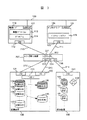
図1に示すように、本実施形態におけるコンピュータシステムでは、業務サーバ110とバックアップサーバ120が、それぞれLANインタフェース111、121を介してLAN100で接続される。業務サーバ110は、I/Oインタフェース112、バス101を介して記憶装置130のI/Oインタフェース131に接続される。バックアップサーバ120は、I/Oインタフェース122、バス102を介して記憶装置130のI/Oインタフェース132と、保存装置140のI/Oインタフェース141に接続される。
【0008】
業務サーバ110内で動作する業務アプリケーション113及びデータベース114の使用するデータは、記憶装置130の記憶領域部分(134,135,136,137)に格納されている。すなわち、記憶装置130の記憶領域は、N個に等分割された記憶領域部分1(134)〜記憶領域部分N(137)として構成されている。記憶装置130にはまた、1個の複製領域1(138)及び1個の差分領域1(139)が形成されている。なお、複製領域1(138)の容量は、1個の記憶領域部分の容量と等しい。
【0009】
バックアップサーバ120内には、複製領域138から複数の保存領域(143,144,145)へのバックアップを制御するバックアップソフトウェア123が保持されている。バックアップソフトウェア123はまた、差分領域1(139)への差分データのバックアップも制御する。
【0010】
記憶装置130内のコントローラ133は、業務サーバ110から記憶領域部分1(134)〜記憶領域部分N(137)へのデータのリードライト制御、およびバックアップサーバ120から複製領域138へのデータのリードライト制御、さらに記憶領域部分1〜Nから複製領域138へのデータのコピー制御を行っている。
【0011】
保存装置140内のコントローラ142は、バックアップサーバ120から保存領域(143,144,145)へのデータのリードライト制御を行っている。
【0012】
バックアップソフトウェア123は、ユーザからのバックアップ開始の指示やバックアップ対象の指定を受け付け、記憶装置130の複製領域138から保存装置140の保存領域(143,144,145)にデータを転送するための“データ転送機能”、及び、データ転送のタイミングと連動し、転送処理の前後に記憶装置のコントローラと連携を取るための“ペア制御連携機能”を有する。
【0013】
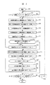
図2により、バックアップソフトウェア123の動作を説明する。
バックアップソフトウェア123は、記憶領域部分1(134)のバックアップ要求(n=1)があると(ステップ202)、まず始めに記憶領域部分1(134)と複製領域1(138)をペア状態とし(ステップ204)、残りの記憶領域部分(135,136,137)は差分領域1(139)とペア状態にする(ステップ206)。次に、記憶領域部分1(134)のデータを複製領域1(138)へコピーする(ステップ208)。そして一旦ペア状態を解除し、記憶領域部分1(134)と複製領域1(138)を切り離す(ステップ210)。
バックアップソフトウェア123は、さらに、複製領域1(138)からデータを読み出し保存領域1(143)へバックアップする(ステップ212)。もし、保存領域1(143)に複製領域1(138)のデータが入りきらない場合は、続いてこれを保存領域2(144)へバックアップする(ステップ214〜216)。
【0014】
ペア状態ではない記憶領域部分(135,136,137)は差分領域1(139)とペア状態となっており、前回バックアップ時からの差分データが差分領域1(139)に記録される(ステップ218)。さらに、バックアップソフトウェア123により差分データ1(139)のデータも読み出され保存領域1(143)へバックアップされる(ステップ220)。もし保存領域1(143)にデータが入りきらない場合は続いて保存領域2(144)へバックアップする(ステップ222〜226)。
【0015】
記憶領域部分1(134)および差分領域1(139)のバックアップが終了したら、次に、新たな記憶領域部分2(135)と複製領域1(138)をペア状態とし(n=2)、記憶領域部分2(135)のデータを複製領域1(138)へコピーする(ステップ230、204〜214)。記憶領域部分2(137)のバックアップ及び差分データのバックアップが終了したらまたこの先同様に、n=Nを1サイクルとして、処理を繰り返し、要求のある限り同様の処理を続行する。
【0016】
各記憶領域部分(134,135,136,137)と複製領域1(138)とがペア状態を組む順序については、必ずしも記憶領域部分の位置の順序通りとは限らず、バックアップソフトウェア123に設定されてある各記憶領域部分毎のバックアップスケジューリングに合わせ、ペア制御連携機能により記憶装置130のコントローラ133と連携し、任意の順序で実施することが出来る。
【0017】
保存領域(143,144,145)にバックアップされたデータを、記憶領域部分(134,135,136,137)へリストアするリストア処理も、上記バックアップ取得処理と同様な手順で行なわれる。
本実施形態での、第1のリストア処理方式は、バックアップソフトウェア123より、保存領域(143,144,145)にバックアップされたデータを、記憶領域部分(134,135,136,137)へリストアする要求があった場合、ペア状態を対象データの存在する記憶領域部分に切り替え、保存領域(143,144,145)から対象となるデータをバックアップサーバ120が読み出し、複製領域138へ書き込む。複製領域への書き込みが終了したら、業務サーバ110のデータベース114から記憶装置130へのアクセスを一時中断し、複製領域138から記憶領域部分(134,135,136,137)へ書き込み、その後データベース114からのアクセスを再開する。
本実施形態での、第2のリストア処理方式は、バックアップソフトウェア123より、保存領域(143,144,145)にバックアップされたデータを、記憶領域部分(134,135,136,137)へリストアする要求があった場合、保存領域(143,144,145)から対象となるデータをバックアップサーバ120が読み出し、LAN100経由にてデータを業務サーバ110に送り、業務サーバ110は対象記憶領域部分(134,135,136,137)へ書き込む。
【0018】
本実施形態によれば、記憶領域を複数に分割し、順次複製領域とペアを組み、保存領域へバックアップすることにより、複製領域の少容量化を図ることができる。以下、この点について説明する。
まず、先に述べたとおり、本実施形態によれば複製領域1(138)の必要容量は、1個の記憶領域部分の容量と等しい。
ここで、記憶領域の分割数をN(整数)とし、差分データ量が記憶データ量に対して1/Mになると仮定する。すると、差分領域1の容量は、(N−1)/Mとなる。
一方、複製領域が記憶領域と同容量の領域を必要とする従来方式では、複製領域1の他に(N−1)の複製領域が必要になる。
複製領域と差分領域との合計容量Cを計算すると、
上記従来方式(X)では、CX=N
本実施形態(Y)では、CY=1+((N−1)/M)となる。
CX/CY=N/(1+((N−1)/M))=NM/(M+N−1)………(1)
差分領域1のデータが実際にどの位になるかということは、記憶領域に対するデータ更新度合がどれ位になるかということによって決まる。本実施形態において記憶領域の1/Mが更新されるということは、常に1/Mは保証されることになる。一般的には、差分領域1の容量は記憶装置130の記憶領域の容量に比べて小さいもので良く、例えば、1/M=0.1程度で足りる。仮に1個の記憶領域部分記憶装置130の記憶領域の分割数Nを2とし、M=10とした場合、(1)式から、CX/CY=NM/(M+N−1)=20/11≒1.8なり、本実施形態(Y)のほうが、従来方式(X)よりも複製領域の容量を少なくすることができる。
次に、分割数Nを10とし、M=10とした場合、CX/CY≒5.26となり、本実施形態(Y)のほうが、従来方式(X)よりも複製領域の容量を大幅に少なくすることができる。
このように、(1)式から、N≧2、M>1とすることで、従来方式(X)よりも本実施形態(Y)のほうが、常に複製領域の容量を少なくできる。すなわち、本実施形態によれば、複製領域1と差分領域1を含む記憶装置130内のトータルの記憶領域容量が、常に記憶領域(134,135,136,137)の容量の2倍未満となり、システム構築コストを低減できる。
このように、本実施形態によれば、記憶領域を分割し、順次複製領域とペアを組み、保存領域へバックアップすることにより、複製領域の少容量化を図ることができる。これにより、投資コストを押さえることが可能となる。
また、複製領域の容量が少なくなるので、一回のバックアップに掛かる時間を節約することも可能となる。
【0019】
図3は、本発明の第2の実施形態におけるコンピュータシステムの構成を示す簡略なブロック図であり、業務サーバ110、バックアップサーバ120、記憶装置130、保存装置140は、I/O切替え装置200を介して相互に接続されている。
【0020】
図3に示すように、本実施形態におけるコンピュータシステムでは、業務サーバ110は、I/Oインタフェース112、バス210を介してI/O切替え装置200のI/Oインタフェース201に接続される。バックアップサーバ120は、I/Oインタフェース122、バス211を介してI/O切替え装置200のI/Oインタフェース202に接続される。
記憶装置130のI/Oインタフェース131は、バス212を介してI/O切替え装置200のI/Oインタフェース203に接続される。記憶装置130のI/Oインタフェース132は、バス213を介してI/O切替え装置200のI/Oインタフェース204に接続される。保存装置140のI/Oインタフェース141は、バス214を介してI/O切替え装置200のI/Oインタフェース205に接続される。
【0021】
I/O切替え装置200は、装置内のI/Oインタフェース間でのアクセスを制限する機能を持ち、今I/Oインタフェース201とI/Oインタフェース203へはそれ以外のI/Oインタフェースからのアクセスを制限されている。また、I/Oインタフェース202とI/Oインタフェース204、I/Oインタフェース205へはそれ以外のI/Oインタフェースからのアクセスを制限されている。この状態では、図1の接続状態と論理的に何ら変わらない接続状態を実現することが出来、誤った装置へのデータの変更が行われないようになっている。
【0022】
このほかの構成、各部の機能については、第1の実施形態と同様であり、ここでは説明を省略する。
【0023】
本実施形態におけるバックアップ取得処理及びリストア処理は、第1の実施形態とほぼ同様に実施される。
本実施形態でも、記憶領域を分割し、順次複製領域とペアを組み、保存領域へバックアップすることにより、複製領域の少容量化を図ることができる。これにより、投資コストを押さえることが可能となる。また、複製領域の容量が少なくなるので、一回のバックアップに掛かる時間を節約することが可能となる。
【0024】
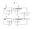
図4は、本発明の第3の実施形態におけるコンピュータシステムの構成を示す簡略なブロック図であり、図1の記憶装置130の記憶領域部分及び複製領域が別筐体となった場合の構成を示している。
【0025】
記憶装置間I/Oインタフェース131,132が直接バス104を介して接続されている。
【0026】
このほかの構成、各部の機能については、第1の実施形態と同様であり、ここでは説明を省略する。
【0027】
本実施形態におけるバックアップ取得処理及びリストア処理は、第1の実施形態とほぼ同様に実施される。
【0028】
図5は、本発明の第4の実施形態におけるコンピュータシステムの構成を示す簡略なブロック図である。業務サーバ110、バックアップサーバ120、記憶装置130、保存装置140は、I/O切替え装置200を介して相互に接続されている。図3の記憶装置130の記憶領域部分及び複製領域が別筐体となった場合の構成を示している。
【0029】
記憶装置間I/Oインタフェース131,132がI/O切り替え装置200のI/Oインタフェース206,207を介して接続されており、ここでもまたI/Oインタフェース206とI/Oインタフェース207はそれ以外のI/Oインタフェースからのアクセスを制限されている。
【0030】
このほかの構成、各部の機能については、第1の実施形態と同様であり、ここでは説明を省略する。
【0031】
本実施形態におけるバックアップ取得処理及びリストア処理は、第1の実施形態とほぼ同様に実施される。
本実施形態でも、記憶領域を分割し、順次複製領域とペアを組み、保存領域へバックアップすることにより、複製領域の少容量化を図ることができる。これにより、投資コストを押さえることが可能となる。また、複製領域の容量が少なくなるので、一回のバックアップに掛かる時間を節約することが可能となる。
【0032】
図6は、今まで述べてきた装置間を遠距離に接続するための接続形態を示したブロック図である。ここで言う装置300及び330は、前述した装置業務サーバ100、バックアップサーバ120、記憶装置130、保存装置140及びI/O切り替え装置200のどの組み合わせもありうるものとする。
【0033】
図6に示すように、装置300と遠距離接続装置310は、各々のI/Oインタフェース(301、311)がバス340を介し接続されている。遠距離接続装置310と遠距離接続装置320は、各々のI/Oインタフェース(312、322)が回線350を介し接続されている。装置330と遠距離接続装置320は、各々のI/Oインタフェース(331、321)がバス341を介し接続されている。
【0034】
図1〜図5に示した接続形態の各I/Oインタフェース間の接続において、図6に示される接続形態で示した遠距離接続形態を組み合わせても、本実施形態におけるバックアップ取得処理及びリストア処理は、第1の実施形態とほぼ同様に実施される。
本実施形態でも、記憶領域を分割し、順次複製領域とペアを組み、保存領域へバックアップすることにより、複製領域の少容量化を図ることができる。これにより、投資コストを押さえることが可能となる。また、複製領域の容量が少なくなるので、一回のバックアップに掛かる時間を節約することが可能となる。
【0035】
【発明の効果】
本発明によれば、記憶領域をN(≧2)に分割し、この分割領域に対応する複製領域を順次切り替えて使用することにより、複製領域の容量を少なくし、投資コストを押さえることが可能となる。
また、複製領域の容量が少なくなるので、一回のバックアップに掛かる時間を節約にすることが可能となる。
【図面の簡単な説明】
【図1】本発明の第1の実施形態によるコンピュータシステムの構成を示す簡略なブロック図である。
【図2】第1の実施形態におけるバックアップソフトウェアの動作を説明するフローチャートである。
【図3】本発明の第2の実施形態によるコンピュータシステムの構成を示す簡略なブロック図である。
【図4】本発明の第3の実施形態によるコンピュータシステムの構成を示す簡略なブロック図である。
【図5】本発明の第4の実施形態によるコンピュータシステムの構成を示す簡略なブロック図である。
【図6】本発明の他の実施形態として、業務サーバ、バックアップサーバ、記憶装置、保存装置、I/O切り替え装置間を遠距離に接続するための接続形態を示す簡略なブロック図である。
【符号の説明】
100・・・LAN(ローカルエリアネットワーク)
101〜103・・・バス(SCSIやFCなどサーバと外部装置もしくは外部装置間を接続するケーブル)
110・・・業務サーバ
111・・・LANインタフェース
112・・・I/Oインタフェース
113・・・業務アプリケーション
114・・・データベース
120・・・バックアップサーバ
121・・・LANインタフェース
122・・・I/Oインタフェース
123・・・バックアップソフトウェア
130・・・記憶装置
131〜132・・・I/Oインタフェース
133・・・記憶装置用コントローラ
134〜137・・・記憶領域部分
138・・・複製領域
139・・・差分領域
140・・・保存装置
141・・・I/Oインタフェース
142・・・保存装置用コントローラ
143〜145・・・保存領域
200・・・I/O切り替え装置
201〜207・・・I/Oインタフェース
210〜214・・・バス(SCSIやFCなどサーバと外部装置もしくは外部装置間を接続するケーブル)
300・・・業務サーバorバックアップサーバor記憶装置or保存装置orI/O切り替え装置
301・・・I/Oインタフェース
310・・・遠距離接続装置
311・・・I/Oインタフェース
312・・・遠距離接続用I/Oインタフェース
320・・・遠距離接続装置
321・・・I/Oインタフェース
322・・・遠距離接続用I/Oインタフェース
330・・・業務サーバorバックアップサーバor記憶装置or保存装置orI/O切り替え装置
331・・・I/Oインタフェース
340〜341・・・バス(SCSIやFCなどサーバと外部装置もしくは外部装置間を接続するケーブル)
350・・・回線[0001]
TECHNICAL FIELD OF THE INVENTION
The present invention relates to a method of using a copy area when creating a high-speed copy in a storage device or between storage devices in a computer system having a storage area and a data copy area for backing up data.
[0002]
[Prior art]
When backing up data in a storage area, it is necessary to suppress access to the storage area and perform backup during that time. For example, in Japanese Patent Application Laid-Open No. H11-163, in order to prevent the performance of online processing from deteriorating during backup processing and perform high-speed backup, data writing from an application to an external storage device is performed by a storage area using middleware on a server. A method of duplicating is disclosed. According to this method, at the time of backup, duplication is stopped, application processing is continued using one storage area, and backup data is transferred from the other storage area to the tape device by the backup program of the backup server. After the backup is completed, the duplexing is restarted by the middleware and the contents of the two storage areas are resynchronized. In this way, by copying the contents of the storage area to a replication area having the same capacity as the storage area before the backup and backing up the data from the replication area, there is no need to access the storage area. There is no need to stop the business using.
[0003]
[Patent Document 1]
JP-A-2002-41345
[Problems to be solved by the invention]
However, in the method described in
SUMMARY OF THE INVENTION An object of the present invention is to provide a computer system having a storage area and a data duplication area for backing up data, capable of reducing the duplication area to a small capacity and reducing the cost and space at the time of system construction, and its computer system. It is to provide a backup method.
It is another object of the present invention to provide a computer system and a backup method thereof that have a storage area and a data replication area for performing data backup and can save the time required for one backup. .
[0005]
[Means for Solving the Problems]
According to a feature of the present invention, in a storage device having a storage area and a copy area, and a storage device including a program for copying data in the storage area to the copy area, the data in the storage area is copied to the copy area. The storage area is divided into N portions, and the divided storage area portions are sequentially divided into a first replication area in the replication area having a capacity of 1 / N (N ≧ 2) of the storage area. To have the function of copying to
Another feature of the present invention is that a storage area is divided into a plurality of parts, a replication area having a smaller capacity than the storage area is time-divided, and backups are sequentially made to the storage area while sequentially switching the pair status.
For the storage area that is not in the pair state, the difference data is recorded in the copy area, thereby backing up all update data at that time while suppressing the capacity of the copy area.
According to the present invention, the capacity of the replication area can be reduced by dividing the storage area, forming a pair with the replication area, and backing up the storage area. Further, the time required for one backup can be saved.
[0006]
BEST MODE FOR CARRYING OUT THE INVENTION
Hereinafter, embodiments of the present invention will be described. First, FIG. 1 is a simplified block diagram showing the configuration of the computer system according to the first embodiment. In the computer system according to the present embodiment, when copying data in a storage area to a replication area, the storage area is divided into N pieces, and copying is sequentially performed for each of the divided storage area portions. That is, one of the divided storage areas is copied to the duplication area, and further backed up to the storage area.
[0007]
As shown in FIG. 1, in the computer system according to the present embodiment, a
[0008]
The data used by the
[0009]
In the
[0010]
The
[0011]
The
[0012]
The
[0013]
The operation of the
When there is a backup request (n = 1) for the storage area part 1 (134) (step 202), the
The
[0014]
The storage area portions (135, 136, and 137) that are not paired are paired with the differential area 1 (139), and the differential data from the previous backup is recorded in the differential area 1 (139) (step 218). ). Further, the data of the difference data 1 (139) is also read out by the
[0015]
After the backup of the storage area part 1 (134) and the differential area 1 (139) is completed, the new storage area part 2 (135) and the replication area 1 (138) are paired (n = 2) and stored. The data of the area part 2 (135) is copied to the duplication area 1 (138) (
[0016]
The order in which the storage areas (134, 135, 136, 137) and the replication area 1 (138) are paired is not necessarily in the same order as the positions of the storage areas and is set in the
[0017]
Restore processing for restoring the data backed up in the storage areas (143, 144, 145) to the storage area portions (134, 135, 136, 137) is also performed in the same procedure as the above-described backup acquisition processing.
In the first restore processing method according to the present embodiment, the data backed up in the storage area (143, 144, 145) by the
In the second restore processing method according to the present embodiment, the data backed up in the storage areas (143, 144, 145) by the
[0018]
According to the present embodiment, it is possible to reduce the capacity of the duplication area by dividing the storage area into a plurality of parts, sequentially forming pairs with the duplication area, and backing up the storage area. Hereinafter, this point will be described.
First, as described above, according to the present embodiment, the required capacity of the duplication area 1 (138) is equal to the capacity of one storage area.
Here, it is assumed that the number of divisions of the storage area is N (integer) and the difference data amount is 1 / M with respect to the storage data amount. Then, the capacity of the
On the other hand, in the conventional method in which the duplication area requires an area having the same capacity as the storage area, an (N−1) duplication area is required in addition to the
When calculating the total capacity C of the replication area and the difference area,
In the above conventional method (X), CX = N
In the present embodiment (Y), CY = 1 + ((N−1) / M).
CX / CY = N / (1 + ((N-1) / M)) = NM / (M + N-1) (1)
The actual data size of the
Next, when the number of divisions N is set to 10 and M = 10, CX / CY ≒ 5.26, and the capacity of the copy area is much smaller in the present embodiment (Y) than in the conventional method (X). can do.
As described above, by setting N ≧ 2 and M> 1 from the expression (1), the capacity of the copy area can always be smaller in the present embodiment (Y) than in the conventional method (X). That is, according to the present embodiment, the total storage capacity of the
As described above, according to the present embodiment, the storage area is divided, pairs are sequentially formed with the duplication area, and backup is performed to the storage area, whereby the capacity of the duplication area can be reduced. This makes it possible to reduce investment costs.
Further, since the capacity of the copy area is reduced, it is possible to save the time required for one backup.
[0019]
FIG. 3 is a simplified block diagram showing a configuration of a computer system according to the second embodiment of the present invention. The
[0020]
As shown in FIG. 3, in the computer system according to the present embodiment, the
The I /
[0021]
The I /
[0022]
Other configurations and functions of each unit are the same as those in the first embodiment, and a description thereof will not be repeated.
[0023]
The backup acquisition processing and the restoration processing in the present embodiment are performed in substantially the same manner as in the first embodiment.
Also in the present embodiment, the capacity of the duplication area can be reduced by dividing the storage area, forming a pair with the duplication area sequentially, and backing up the storage area. This makes it possible to reduce investment costs. Further, since the capacity of the copy area is reduced, it is possible to save the time required for one backup.
[0024]
FIG. 4 is a simplified block diagram showing a configuration of a computer system according to the third embodiment of the present invention. FIG. 4 shows a configuration in a case where a storage area portion and a replication area of the
[0025]
The I / O interfaces 131 and 132 between the storage devices are directly connected via the
[0026]
Other configurations and functions of each unit are the same as those in the first embodiment, and a description thereof will not be repeated.
[0027]
The backup acquisition processing and the restoration processing in the present embodiment are performed in substantially the same manner as in the first embodiment.
[0028]
FIG. 5 is a simplified block diagram showing a configuration of a computer system according to the fourth embodiment of the present invention. The
[0029]
The I / O interfaces 131 and 132 between the storage devices are connected via the I / O interfaces 206 and 207 of the I /
[0030]
Other configurations and functions of each unit are the same as those in the first embodiment, and a description thereof will not be repeated.
[0031]
The backup acquisition processing and the restoration processing in the present embodiment are performed in substantially the same manner as in the first embodiment.
Also in the present embodiment, the capacity of the duplication area can be reduced by dividing the storage area, forming a pair with the duplication area sequentially, and backing up the storage area. This makes it possible to reduce investment costs. Further, since the capacity of the copy area is reduced, it is possible to save the time required for one backup.
[0032]
FIG. 6 is a block diagram showing a connection form for connecting the devices described above to a long distance. The
[0033]
As shown in FIG. 6, the I / O interface (301, 311) of the
[0034]
In the connection between the I / O interfaces in the connection forms shown in FIGS. 1 to 5, even if the long-distance connection form shown in the connection form shown in FIG. Is carried out almost in the same manner as in the first embodiment.
Also in the present embodiment, the capacity of the duplication area can be reduced by dividing the storage area, forming a pair with the duplication area sequentially, and backing up the storage area. This makes it possible to reduce investment costs. Further, since the capacity of the copy area is reduced, it is possible to save the time required for one backup.
[0035]
【The invention's effect】
According to the present invention, the storage area is divided into N (≧ 2), and the copy area corresponding to the divided area is sequentially switched and used, so that the capacity of the copy area can be reduced and the investment cost can be reduced. It becomes.
Further, since the capacity of the copy area is reduced, it is possible to save the time required for one backup.
[Brief description of the drawings]
FIG. 1 is a simplified block diagram showing a configuration of a computer system according to a first embodiment of the present invention.
FIG. 2 is a flowchart illustrating an operation of the backup software according to the first embodiment.
FIG. 3 is a simplified block diagram illustrating a configuration of a computer system according to a second embodiment of the present invention.
FIG. 4 is a simplified block diagram illustrating a configuration of a computer system according to a third embodiment of the present invention.
FIG. 5 is a simplified block diagram showing a configuration of a computer system according to a fourth embodiment of the present invention.
FIG. 6 is a simplified block diagram showing a connection mode for connecting a business server, a backup server, a storage device, a storage device, and an I / O switching device over a long distance as another embodiment of the present invention.
[Explanation of symbols]
100 ... LAN (local area network)
101 to 103... Bus (SCSI, FC, etc., server and external device or cable connecting external device)
110 ...
300 ... business server or backup server or storage device or storage device or I /
350 ・ ・ ・ Line
Claims (10)
前記記憶領域をN(≧2)に分割し、該分割領域を順次、複製領域とペア状態とし、前記複製領域を順次切り替えて使用し、保存領域へバックアップすることを特徴とするコンピュータシステムにおけるバックアップ方法。A backup method in a computer system including a storage device having a storage area and a copy area, and a storage device incorporating a program for copying data in the storage area to the copy area,
A backup method in a computer system, wherein the storage area is divided into N (≧ 2), the divided areas are sequentially paired with a replication area, the replication area is sequentially switched and used, and a backup is made to a storage area. Method.
前記記憶領域をN(≧2)に分割し、該分割した記憶領域部分を順次、前記記憶領域の1/N(N≧2)の容量を有する前記複製領域内の第1複製領域に複製し、
前記記憶領域の複製を行っていない残りの記憶領域部分については、前回の複製時からの差分を前記複製領域内の差分領域に複製し、
前記複製領域内のデータを保存装置の保存領域へバックアップを行うことを特徴とするコンピュータシステムにおけるバックアップ方法。A backup method in a computer system including a storage device having a storage area and a copy area, and a storage device incorporating a program for copying data in the storage area to the copy area,
The storage area is divided into N (≧ 2), and the divided storage area portions are sequentially copied to a first replication area in the replication area having a capacity of 1 / N (N ≧ 2) of the storage area. ,
For the remaining storage area portion where the storage area is not copied, the difference from the previous copy is copied to a difference area in the copy area,
A backup method in a computer system, wherein data in the replication area is backed up to a storage area of a storage device.
Priority Applications (1)
| Application Number | Priority Date | Filing Date | Title |
|---|---|---|---|
| JP2002363304A JP2004199116A (en) | 2002-12-16 | 2002-12-16 | Division back-up/restoration application system |
Applications Claiming Priority (1)
| Application Number | Priority Date | Filing Date | Title |
|---|---|---|---|
| JP2002363304A JP2004199116A (en) | 2002-12-16 | 2002-12-16 | Division back-up/restoration application system |
Publications (1)
| Publication Number | Publication Date |
|---|---|
| JP2004199116A true JP2004199116A (en) | 2004-07-15 |
Family
ID=32761484
Family Applications (1)
| Application Number | Title | Priority Date | Filing Date |
|---|---|---|---|
| JP2002363304A Pending JP2004199116A (en) | 2002-12-16 | 2002-12-16 | Division back-up/restoration application system |
Country Status (1)
| Country | Link |
|---|---|
| JP (1) | JP2004199116A (en) |
Cited By (2)
| Publication number | Priority date | Publication date | Assignee | Title |
|---|---|---|---|---|
| JP2007122167A (en) * | 2005-10-25 | 2007-05-17 | Fujitsu Ltd | Data transfer program, data transfer method, and data transfer unit |
| JP2009043054A (en) * | 2007-08-09 | 2009-02-26 | Hitachi Ltd | Storage system and backup method |
-
2002
- 2002-12-16 JP JP2002363304A patent/JP2004199116A/en active Pending
Cited By (2)
| Publication number | Priority date | Publication date | Assignee | Title |
|---|---|---|---|---|
| JP2007122167A (en) * | 2005-10-25 | 2007-05-17 | Fujitsu Ltd | Data transfer program, data transfer method, and data transfer unit |
| JP2009043054A (en) * | 2007-08-09 | 2009-02-26 | Hitachi Ltd | Storage system and backup method |
Similar Documents
| Publication | Publication Date | Title |
|---|---|---|
| US9087013B2 (en) | Methods and apparatus for point-in-time volumes | |
| JP4148722B2 (en) | Online data migration method | |
| US6938135B1 (en) | Incremental backup of a data volume | |
| JP4454342B2 (en) | Storage system and storage system control method | |
| US7194487B1 (en) | System and method for recording the order of a change caused by restoring a primary volume during ongoing replication of the primary volume | |
| US7293068B2 (en) | Method and system for storing duplicate data | |
| US8028139B2 (en) | Remote copy method and remote copy system | |
| EP1424632A2 (en) | Storage system snapshot creating method and apparatus | |
| JP4170056B2 (en) | Backup / restore management method between replicated volumes and storage control device used in this method | |
| JP2006268139A (en) | Data reproduction device, method and program and storing system | |
| JP3610574B2 (en) | Disk array device | |
| JP2007141183A (en) | Storage controller and storage control method | |
| US7194675B2 (en) | Backup method, backup system, disk controller and backup program | |
| JP4512386B2 (en) | Backup system and method | |
| JP2004199116A (en) | Division back-up/restoration application system | |
| JP3253473B2 (en) | Method and apparatus for resynchronization processing of duplicated shared memory | |
| JP4131621B2 (en) | Distributed mirrored disk system | |
| JPH07281933A (en) | Computer system | |
| JP2004070456A (en) | Data backup method, data backup device, and information processing unit | |
| JP3463696B2 (en) | Online garbage collection processing method | |
| JPH08241220A (en) | Online capacity extending method for external storage device | |
| JPH08110840A (en) | Restoration system for magnetic disk device of double redundancy constitution | |
| JP2666426B2 (en) | Duplex auxiliary storage device | |
| JP2850756B2 (en) | Failure recovery method for files in distributed processing system | |
| JPH10240620A (en) | Computer system and check point image preservation method in the system |