JP2004197864A - Frictional driving device - Google Patents
Frictional driving device Download PDFInfo
- Publication number
- JP2004197864A JP2004197864A JP2002368304A JP2002368304A JP2004197864A JP 2004197864 A JP2004197864 A JP 2004197864A JP 2002368304 A JP2002368304 A JP 2002368304A JP 2002368304 A JP2002368304 A JP 2002368304A JP 2004197864 A JP2004197864 A JP 2004197864A
- Authority
- JP
- Japan
- Prior art keywords
- piezoelectric element
- roller
- pressing
- drive shaft
- amount
- Prior art date
- Legal status (The legal status is an assumption and is not a legal conclusion. Google has not performed a legal analysis and makes no representation as to the accuracy of the status listed.)
- Granted
Links
Images


Abstract
Description
【0001】
【発明の属する技術分野】
本発明は、駆動軸を回転させることによって移動体を進退させる摩擦駆動装置に係り、特に光ディスク原盤に対してトラックピッチを正確に露光する移動体であるスライドテーブルを具備する光ディスク原盤露光装置における移動体駆動部に適用される摩擦駆動装置に関する。
【0002】
【従来の技術】
従来、光ディスク原盤露光用のスライドテーブル装置においては、高精度送りを実現するための発明が数多くなされている(特許文献1〜3)。
【0003】
光ディスク原盤露光用のスライドテーブル装置では、静圧軸受を介してスライドテーブルを進退自在に設けたエアスライド式のスライドテーブル装置が用いられている。スライドテーブルの駆動は、ボイスコイル型のリニアモータが一般的に用いられ、位置検出器として干渉レーザ測長器あるいはリニアスケールを使用した閉ループ制御方式が採用されている。また、半導体検査装置等の静止状態を必要とするものでは、送り方向の剛性を必要とするためスライドテーブルの駆動にボールネジなどを用いる。
【0004】
近年の光ディスクの高密度化に伴い、より高解像の露光を実現するために従来のレーザビームから電子線などを用いた露光法が登場し、それに伴い真空環境への対応、および、より高精度な送りが必要になってきている。
【0005】
摩擦駆動機構のツイストローラ方式は、駆動軸と従動軸との間の交差角を微小にすることにより、他の機構では得られない小さなリードを実現することが可能になり、高い位置決め分解能が期待できることから、次世代の送り機構として特許文献,非特許文献に様々な機構が提案されている。
【0006】
例えば特許文献4に記載の発明は、軸体と、この軸体を相対的に回転および進退自在に貫通させた進退部品とを備え、進退部品として進退部品本体内に軸体に転接する樽形のローラを周方向に並べて複数個設け、これらのローラを、両端面においてボールを介して進退部品本体と予圧板との間に回転自在に支持する構成であり、進退部品本体とローラ端面との少なくとも一方、および予圧板とローラ端面との少なくとも一方が、ボールが回転自在に嵌まる円錐面状のボール支持凹部でボールの支持を行わせる構成である。また、予圧板をローラ側へ付勢すると共に円周方向に付勢する弾性体を設けることにより、耐外乱性が高く、速度むらがなく、安定送りが行え、また駆動源において停止時における静止性能の向上を図れることができる装置としている。
【0007】
特許文献5に記載の発明は、テーブルとなるスライド体を基台に対して静圧直動軸受で静圧支持し、基台に対してスライド体をスライド自在に駆動する摩擦進退駆動装置を設けるものであり、摩擦進退駆動装置は、回転駆動される主軸と、この主軸の周りに複数設けられて各々傾き角度を持って接するローラとを備え、このローラに主軸に対する予圧を与える予圧手段を設けて、速度むらが生じることなく、安定した送りが行え、外乱にも強く、分解能の向上を図り、これにより高密度の書き込みを可能にした光ディスクマスタリング装置用のスライドテーブル装置としている。
【0008】
特許文献6に記載の発明は、主軸と、この主軸の外周に傾き角度をもって転がり接触するローラと、主軸の回転に伴いローラと共に移動するスライド体とを備えたものであり、モータの回転は減速機で減速して主軸に伝達し、この減速機を、第1,第2の駆動側軸から摩擦車への回転伝達で減速する構成にして、回転駆動源の回転むらの影響を少なくすると共に、回転伝達系における位相ずれを少なくし、精密な位置決めを可能としている。
【0009】
特許文献7に記載の発明は、入力駆動軸と、駆動軸外周にころがり接触し、かつ駆動軸軸線に対して微小な交差角をもって傾斜した軸線をそれぞれ有する複数個の従動軸であるローラと、前記駆動軸に対してローラを外接支持し、かつ駆動軸の回転に起因してローラが発生させる摩擦力の軸方向分力によって軸方向に移動するようにされたハウジングとを有する摩擦駆動装置において、ローラをラジアルおよびスラストの各静圧軸受を介して前記ハウジングにて保持し、ハウジングのローラ端面に面するスラスト静圧軸受面を、駆動軸とローラの各軸線とを通る線に対して線対称な2個の半円部に分割し、各半円部に別個に供給される静圧圧力を調整して前記交差角を安定して保持させる構成としている。
【0010】
【特許文献1】
特開2002−25128号公報
【特許文献2】
特開2002−92973号公報
【特許文献3】
特開2002−279700号公報
【特許文献4】
特開平8−184360号公報
【特許文献5】
特開平11−195247号公報
【特許文献6】
特開平11−195248号公報
【特許文献7】
特公平6−23598号公報
【0011】
【発明が解決しようとする課題】
ところで、特許文献4に記載の発明の場合、ローラが駆動軸心に対して等角(120度)に配置される構成であるため、ローラ端面を支持している固定板および対向板に各々形成される円錐面状のボール支持凹部の機械的な位置誤差のために、各ローラ軸心と駆動軸とのなす角度にばらつきを生じやすい。
【0012】
このことは、ローラ軸芯と駆動軸とがなす角度を大きく、言い換えるとリード(軸方向に進む距離)を比較的大きく取る場合(例えば数mm)には問題とならないが、ローラ軸芯と駆動軸とのなす角度を小さく、言い換えるとリードを小さく取る場合(例えば数百μm)に、各ローラ軸芯と駆動軸とのなす角度にばらつきがあると、駆動軸と従動軸のローラとの間においてリード誤差によるすべりを生じ、これが閉ループ制御の外乱となるため、制御上好ましくないと共に、光ディスク原盤露光などに適用するとトラックピッチ精度などが悪くなり、露光品質上好ましくないという問題がある。
【0013】
また、従来のツイストローラ方式の摩擦駆動装置においては、従動軸が回転するために、その支持が問題となる。滑り接触による支持では隙間の存在が不可欠であり、さらに、転がり接触による支持では転動体を真円とすることが不可能であるため、微視的に言えばローラは振動しながら回転することになり、ローラの交差角を常時安定して保持することができないという問題がある。その問題を特許文献7に記載の発明では、ローラを静圧支持することにより安定化を図るようにしているが、構成要素が高価となる。
【0014】
また、特許文献4に記載の発明では、予圧板をローラ側へ付勢すると共に円周方向に付勢する弾性体を設ける構成としており、ローラの軸体に対する予圧量の調整は、進退部品本体に設けたネジ部を有する孔部と予圧板に設けた孔部を連通させた位置として、その連通孔部に弾性体を設けて進退部品本体に設けたネジ部のイモネジを締めることによる弾性体の圧縮変形力を利用している。このような構成の場合、ローラの軸体に対する現在予圧量を定量的に確認することができないため、適正な予圧量にするために試行錯誤が必要となり、またローラあるいは軸体の磨耗による経年変化に伴う予圧の再調整も困難となり、部品交換時の予圧量再現性もなく組立性が悪いという問題がある。
【0015】
特許文献5に記載の発明では、ローラに主軸に対する予圧を与える予圧手段を設けているが、基台に固定される静圧直動軸受の固定部と摩擦進退駆動装置の主軸との間に真直性に誤差がある状態で組み立てされるおそれがある。この場合、スライド体が送り方向に動作すると、予圧をかけられて固定されているだけで、剛性が最も低いローラと主軸との間において、その真直誤差を吸収することになるため、ローラの主軸に対する予圧量が移動位置と共に変化する。
【0016】
駆動軸と1つのローラ間に働く駆動軸方向の駆動力は、駆動軸外周とローラ間の動摩擦係数をμ、予圧をNとするとF=μNとなる。したがって、各々のローラと駆動軸外周で発生する駆動力にもばらつきを生じ、これにより、各々の駆動力にもばらつきを生じるため、各ローラの軸心と駆動軸とがなす角度のばらつきと相乗して、駆動軸と従動軸のローラとの間ですべりを生じ、これが閉ループ制御の外乱となるため制御上好ましくなく、光ディスク原盤露光などに適用する場合には、トラックピッチ精度などが悪くなり、露光品質上好ましくない。
【0017】
本発明は、前記従来の問題が生じることなく、高精度送りを実現することができる光ディスク原盤露光装置などに適用することを可能にした摩擦駆動装置を提供することを目的にする。
【0018】
【課題を解決するための手段】
前記目的を達成するため、請求項1に記載の発明は、駆動軸とその外周にころがり接触し、かつ前記駆動軸の軸線に対して微小な交差角をもって傾斜した軸線を有する複数個の従動軸に設けられたローラと、前記駆動軸に対して前記ローラを外接支持し、かつ前記駆動軸の回転に起因して前記ローラが発生させる摩擦力の軸方向分力によって軸方向に移動されるハウジングと、このハウジングと共に移動する移動体と、この移動体を前記駆動軸の軸線方向に案内する案内機構と、前記移動体の送り位置を検出する位置検出手段とを備えた摩擦駆動装置において、前記従動軸の一端を前記ハウジングにより支持し、かつ他端を前記ローラが前記駆動軸の外周に押圧する方向に伸縮する第1の圧電素子および前記駆動軸の外周における接線方向に押圧する方向に伸縮する第2の圧電素子を介して前記ハウジングにより支持し、さらに前記第1の圧電素子への印加電圧を制御する第1の出力手段と、送りの設定リード量に対して前記従動軸の傾き角度を算出する角度算出手段と、算出された算出角度に相当する出力電圧を第2の圧電素子に印加する第2の出力手段と、前記駆動軸を回転駆動する送り駆動モータの回転角度を検出するロータリーエンコーダにおける1回転当たりの原点検出信号および前記位置検出手段の位置検出信号に基づいて現在リード量を算出する現在リード量算出手段と、現在リード量と設定リード量を比較して前記第2の圧電素子への印加電圧を増減する電圧補正手段とを具備した角度調整手段を備えたことを特徴とし、この構成によって、加工,組み付け誤差などによる機械的な位置誤差のために生じる各従動軸と駆動軸とのなす交差角度のばらつきを補正することができるようにしているため、各ローラの軸心と駆動軸とのなす角度が精密に設定され、駆動軸と各従動軸のローラ間でリード誤差によるすべりが発生せず、安定した送り制御を実現することができ、送り精度の向上を図ることができる。
【0019】
請求項2に記載の発明は、請求項1記載の摩擦駆動装置は、従動軸を弾性体と剛体との複合材料から構成したことを特徴とし、この構成によって、従動軸とローラの角度調整,取り付けを容易かつ確実に行うことができる。
【0020】
請求項3に記載の発明は、請求項1または2記載の摩擦駆動装置において、ローラを、該ローラの半径方向に着磁された磁石の反発力により構成するラジアル磁気軸受と、該ローラの軸線方向に着磁された磁石の反発力により構成するスラスト磁気軸受とを介して従動軸に保持したことを特徴とし、この構成によって、ローラは、ラジアル磁気軸受とスラスト磁気軸受を介して従動軸に非接触で保持されているため、従来のようなアンギュラ軸受などで用いられる転動体で発生する振動などがなくなり、安定したリードが行え、安定した送り制御が可能となり、送り精度をさらに向上させることができる。
【0021】
請求項4に記載の発明は、請求項3記載の摩擦駆動装置において、ラジアル磁気軸受およびスラスト磁気軸受を構成する磁石として希土類永久磁石を用いたことを特徴とし、この構成によって、体積の小さい磁石で大きな反発力が得られることになるため、装置を小型に構成することができると共に安価に実現できる。
【0022】
請求項5に記載の発明は、請求項1,3または4記載の摩擦駆動装置において、従動軸とローラと駆動軸とハウジングとを、非磁性材料にて構成したことを特徴とし、この構成によって、磁石による他部品への吸引力を防止することができるため、押圧制御および従動軸の角度制御への外乱をなくすことができ、よって、さらに送り精度の向上を図ることができる。
【0023】
請求項6に記載の発明は、請求項1記載の摩擦駆動装置において、第1の出力手段を、定電圧回路と、この定電圧回路の出力信号が入力され、かつ外部信号によりオン/オフする切換スイッチと、第1の圧電素子に設けた変形量測定手段と、前記切換スイッチの出力信号である押圧伸縮設定信号と前記変形量測定手段の出力信号である現在押圧伸縮量とを比較してサーボ制御するサーボ制御手段から構成したことを特徴とし、この構成によって、ローラの駆動軸外周への押圧(予圧)動作と、各従動軸と駆動軸との交差角度を補正する角度補正動作を再現性よく行えるため、安定した送り制御が実現でき、送り精度の向上を図ることができる。
【0024】
請求項7に記載の発明は、請求項1記載の摩擦駆動装置において、ハウジングに第1の圧電素子を押圧可能に第1の調整板を設け、前記第1の調整板と前記第1の圧電素子を介して第1の調整ネジによって従動軸における駆動軸の外周方向に押圧する位置の調整を可能にし、さらに前記ハウジングに、第2の圧電素子を押圧可能に第2の調整板を設け、前記第2の調整板と前記第2の圧電素子を介して第2の調整ネジによって、前記駆動軸の外周における接線方向に押圧する方向の前記従動軸における位置を調整可能にしたことを特徴とし、この構成によって、大きな交差角度でも角度補正動作が行えることになるため、広いリード条件範囲において安定した送り制御を実現することができ、送り構成要素としての汎用性を高くすることができる。
【0025】
請求項8に記載の発明は、請求項1記載の摩擦駆動装置において、第1の出力手段を、可変電圧回路と、この可変電圧回路の出力信号が入力され、かつ外部信号によりオン/オフする切換スイッチと、前記従動軸の弾性体の外周部に該従動軸の押圧方向における変形量を検出する変形量測定手段を設け、前記切換スイッチの出力信号である押圧設定信号と変形量測定手段の出力信号である現在押圧量とを比較してサーボ制御するサーボ制御手段から構成したことを特徴とし、この構成によって、ローラの駆動軸に対する押圧量を従動軸の変形量に置換した信号で予圧サーボをするため、適正な押圧条件に瞬時に設定することができ、ローラあるいは駆動軸の磨耗による経年変化に伴う押圧の再調整が容易であり、部品交換時の押圧量再現性も良好になるなど、組立性の向上が図ることができる。
【0026】
請求項9に記載の発明は、請求項1記載の摩擦駆動装置において、第1の出力手段を、1つのデジタル/アナログ変換器と、変形量測定手段と、前記デジタル/アナログ変換器の出力信号である押圧設定信号と前記変形量測定手段の出力信号である現在押圧量とを比較してサーボ制御するサーボ制御手段から構成したことを特徴とし、この構成によって、ローラの駆動軸に対する押圧量を従動軸の変形量に置換した信号で押圧サーボをするため、適正な押圧条件に瞬時に設定することができ、ローラあるいは駆動軸の磨耗による経年変化に伴う押圧の再調整が容易であり、部品交換時の押圧量再現性も良好になるなど、組立性の向上が図ることができる。
【0027】
請求項10に記載の発明は、請求項1記載の摩擦駆動装置において、第1の出力手段を、第1の圧電素子への押圧設定信号を独立に与える複数のデジタル/アナログ変換器と、変形量測定手段と、前記複数のデジタル/アナログ変換器の出力信号である押圧設定信号と前記変形量測定手段の出力信号である現在押圧量とを比較してサーボ制御するサーボ制御手段から構成したことを特徴とし、この構成によって、ローラの駆動軸に対する押圧量を従動軸の変形量に置換した信号で押圧サーボを行い、かつ各押圧手段への押圧設定値を独立に与えるようにしているため、各ローラと駆動軸の外周で発生する駆動力にばらつきが発生せず、長ストロークの駆動でも安定した送り動作が実現でき、送り制御精度および組立性の向上を図ることができる。
【0028】
請求項11に記載の発明は、請求項1記載の摩擦駆動装置において、第2の出力手段を、デジタル/アナログ変換器と、第2の圧電素子に設けた変形量測定手段と、前記デジタル/アナログ変換器の出力信号である押圧伸縮設定信号と前記変形量測定手段の出力信号である現在押圧伸縮量とを比較してサーボ動作を行うサーボ制御手段から構成したことを特徴とし、この構成によって、ローラの駆動軸外周への押圧(予圧)動作と、各従動軸と駆動軸との交差角度を補正する角度補正動作を再現性よく行えるため、安定した送り制御が実現でき、送り精度の向上を図ることができる。
【0029】
【発明の実施の形態】
以下、本発明の実施形態を図面に基づいて説明する。
【0030】
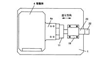
図1は本発明の実施形態1を説明するための摩擦駆動装置の平面図、図2は実施形態1の摩擦駆動装置の右側面図、図3は実施形態1の摩擦駆動装置の一部を断面して示す縦断面図、図4は実施形態1の図3におけるA−A断面図である。
【0031】
図2に示すように、空気圧によるサーボマウンタなどからなる除振機構(図示せず)上に設けられたベース1には、送り方向に対して直交する方向に離間して下端をベース1に固定して複数の支柱2が立設されており、各支柱2の上端には、送り方向に配置したころがり軸受(例えば球体,円筒ローラなど)3を介して移動体4が固定されている。移動体4における左側端部の下部には、出力が任意の分解能のA相,B相パルスから構成される光学式リニアエンコーダなどからなる位置検出手段7が設けられている。
【0032】
本例では位置検出手段7は、送り方向の位置を計測するため受光部5とスケール6から構成しており、スケール6は取付板8を介して移動体4に固定されており、また受光部5が取付板9を介してベース1に固定されている。なお、受光部5とスケール6との取り付け構造として、受光部5を移動体4に固定し、スケール6をベース1に固定する構造にしてもよい。
【0033】
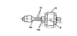
また図3,図4に示すように、移動体4において送り方向に延出する突出部4aの下部には、駆動軸10が貫挿される孔部11aを有するハウジング11が、固定板12を介して固定されている。駆動軸10の外周には、ころがり接触する複数のローラ13(本例では3個を例示している)を、対向したころがり軸受(例えばアンギュラ軸受など)14を介して、図4に示すように、同心状にかつ駆動軸10の中心軸線に対して円周方向に等角に配設している。各ローラ13は、図3,図5に示すように、弾性体(例えばりん青銅棒など)15aと剛体15bの複合材料からなる従動軸16に保持されている。
【0034】
従動軸16の一端部(図3における右側端部)は、図4に示すように、ハウジング11内において、ローラ13が駆動軸10の外周を押圧する方向に伸縮する複数(本例では3つを例示している)の第1の圧電素子17と、ローラ13を駆動軸10の外周接線方向に押圧する方向に伸縮する複数(本例では3つを例示している)の第2の圧電素子18とを介してハウジング11に固定されている。
【0035】
図3に示すように、駆動軸10の右側端部は段付になっており、第1段10aの外周がころがり軸受20の内周部に嵌合している。すなわち、第1段10aの外周は、ベース1に固定されかつ上部に段付の貫通孔19aが設けられた軸受ハウジング19における貫通孔19aに同心状にその外輪を固定した一対のころがり軸受(例えばアンギュラ軸受など)20の内周部に嵌合している。ころがり軸受20の内周部と駆動軸10に設けたネジ部とは軸受止め21にて固定されている。
【0036】
さらに、駆動軸10の第2段10bは、軸受ハウジング19の右側円筒孔部に固定され、かつロータリーエンコーダ(例えば、その出力が一周を数千等分割したA相,B相パルスと一周に1回発生するZ相パルスから構成される)22を備えた送り駆動モータ23の駆動軸に対して、カップリング(例えばオルダム式など)24により連結されている。
【0037】
一方、駆動軸10における左側端部の段付部10cの外周は、ベース1に固定された軸受ハウジング25の上部に設けられた貫通孔25aに、同心状に固定されたころがり軸受(例えば深溝玉軸受など)26の内輪に嵌合しており、ころがり軸受26の外輪は軸心方向に移動可能な構成になっている。
【0038】
前記構成の実施形態1において、第1の圧電素子17と、第2の圧電素子18の端末リード線(図示せず)から、適当な通電電圧を第2の圧電素子18,第1の圧電素子17の順に印加すると、図5の点線に示すように、ある角度θで交差した状態でローラ13の外周と駆動軸10の外周がころがり接触する。この状態で送り駆動モータ23の端末(図示せず)から通電すれば、ローラ13の外周と駆動軸10の外周の接触点は螺旋状に移動して、移動体4が送り方向に移動自在となる。このとき従動軸16自体は回転せず、ころがり軸受14の外輪が回転する外輪回転となる。
【0039】
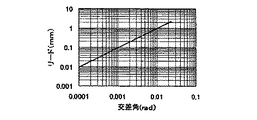
また、駆動軸10が1回転当たりに移動体4を移動させる移動量L(リード量)は、駆動軸10の外形寸法をDとすれば下式(数1)で表すことができる。
【0040】
【数1】
L=π・D・sinθ≒π・D・θ
θ=sin-1{L/(π・D)}
例えばD=30mmとした場合の交差角度とリード量Lとの関係は、図6の両対数グラフに示すように線形となる。
【0041】
次に,実施形態1の従動軸16における角度調整を行うための制御系について図7のブロック図を参照して説明する。
【0042】
割り込み用信号としてロータリーエンコーダ22の一周に1回発生するZ相パルス信号28と送り位置を検出する位置検出手段7のA相パルス信号29とが入力されるCPU(中央演算処理部)30には、動作プログラムが書き込まれたROM(リード・オンリー・メモリ)31とデータを記憶するRAM(ランダム・アクセス・メモリ)32と、Z相パルス信号28の立ち上がりをトリガー信号として位置検出手段7のA相パルス信号29のパルス数をカウントするカウンタ(例えば同期型カウンタ)33とが接続されている。
【0043】
さらにCPU30は、固定の定電圧を出力する定電圧回路34の出力信号をON/OFFするスイッチ35の駆動信号を出力し、このスイッチ35を介して各第1の圧電素子17にそれぞれ接続された駆動アンプ36に信号出力する。前記定電圧回路34とスイッチ35と駆動アンプ36にて第1の出力手段37を構成している。さらにCPU30にはリード量データLとその設定許容誤差データεを入力するデータ入力部38が接続されている。
【0044】
また、CPU30の出力信号は、デジタルデータをアナログ信号に変換するデジタル/アナログ(D/A)変換器39を介して各第2の圧電素子18にそれぞれ接続された駆動アンプ40に出力される。ここで、前記D/A変換器39と駆動アンプ40にて第2の出力手段41を構成している。
【0045】
実施形態1では図7に示す前記構成全体で角度調整手段42を構成している。
【0046】
前記構成の実施形態1におけるCPU30のコントロールに基づく動作フローを図8,図9に示すフローチャートを参照して説明する。
【0047】
CPU30は、予め入力されたリード量データLと、それに対する設定許容誤差データεを読み込み(S1)、図示しない装置全体のホストコンピュータから指令信号45aを待ち(S2)、送り駆動モータ23の回転開始後にホストコンピュータから指令信号45aを受けると、CPU30に具備させた機能である角度算出手段46にて前記(数1)式に基づいて交差角度θの計算を行う(S3)。その後、スイッチ35の駆動信号がOFFされて各第1の圧電素子17への信号がOFFされ、駆動軸10に対する押圧が開放される(S4)。
【0048】
図9のフローに移行し、D/A変換器39に対して角度算出手段46によって計算された交差角度θ(図5参照)に相当するデジタルデータが出力され(S5)、駆動アンプ40を介して第2の圧電素子18に対して、計算された交差角度θに相当する変位電圧が印加され、従動軸16を駆動軸10外周における接線方向に押圧し、その後、さらにスイッチ35への駆動信号がONされて第1の圧電素子17に対して、適当な電圧に設定された定電圧回路34の出力信号が駆動アンプ36を介して出力され、従動軸16を駆動軸10方向に押圧する(S6)。
【0049】
前記状態において、CPU30は、Z相パルス信号28の立ち上りをトリガー信号としてA相パルス信号29のパルス数Ni(i=a,b,c:駆動アンプ36,D/A変換器39の設置数)をカウントするカウンタ33のカウント出力データを取り込み(S7)、位置検出手段7の出力パルス分解能に係るデータと乗算して、移動量を算出するCPU30に具備させた機能である現在リード量算出手段47にて現在リード量Liを求め(S8)、設定リードLとの差分データΔLiを算出する(S9)。
【0050】
前記差分データΔLiが、あらかじめ設定された設定許容誤差データε以下であれば(S10のYes)、その角度データθiをRAM32に記憶する(S11)。また大きい場合(S10のNo)、差分データΔLiが0よりも大きい場合には、計算された角度データを例えばD/A変換器39の最小分解能などに設定された微少量Δθhだけ逐次増加し(S12)、また、ΔLiが0よりも小さい場合は計算された角度データを微少量Δθhだけ逐次減少させる(S13)。この動作をCPU30に具備させた機能である電圧補正手段48にて、ε≧ΔLiとなるまで繰り返して行う。
【0051】
前記動作フローはサブルーチンになっており、前記動作が図7において各駆動アンプ36,各D/A変換器39ごとに順に行われ、全てが完了するとスイッチ35の駆動信号がOFFされて、第1の圧電素子17への信号がOFFとなり開放される(S14)。記憶された各角度データθに相当するデジタルデータがそれぞれD/A変換器39に出力され(S15)、その後、スイッチ35の駆動信号がONされて第1の圧電素子17への信号がONされ、従動軸16を押圧する(S16)。
【0052】
ここでCPU30は、再度、Z相パルス信号28の立ち上がりをトリガー信号としてA相パルス信号29のパルス数Nkをカウントしたカウンタ33のカウント出力データを取り込み(S17)、位置検出手段7の出力パルス分解能と乗算して現在移動量Lkを求め(S18)、設定リードLとの差分データΔLkを算出し(S19)、その差分データΔLkがあらかじめ設定された設定許容誤差データε以下であることを確認し(S20のYes)、図示しないホストコンピュータに設定完了信号45bをONにして送出し、動作を完了する(S21)。
【0053】
実施形態1の構成によれば、加工,組み付け誤差などによる機械的な位置誤差のために各従動軸16と駆動軸10との軸心がなす交差角度にばらつきを生じても、各従動軸16の角度位置を補正することが可能になる。
【0054】
図10は本発明の実施形態2における従動軸の軸受部分の構成を説明するための断面図である。なお、以下の説明において、既に説明した構成部材に対応する部材には同一符号を付して詳しい説明は省略する。
【0055】
図10において、従動軸16を構成する剛体15bの中央外周部と、剛体15bに嵌合するローラ13の内周部とに、同軸状にその半径方向に着磁され、かつ同極同士が対向するように磁石50a,50bを設けて、微小すきまのラジアル磁気軸受51を構成している。また、剛体15bの一端部および剛体15bの他端部にネジ固定される固定板52と、それらに対向するローラ13の両端部には、同軸状にローラ13の軸線方向に着磁され、かつ同極同士が対向するように磁石53a,53bをそれぞれ設けて、微小すきまのスラスト磁気軸受54を構成している。
【0056】
前記軸受構造にて、磁石の反発力により従動軸16に対してローラ13がラジアル方向およびスラスト方向に非接触に保持されることになるため、ローラ13が非接触にて保持され、アンギュラ軸受などで用いられる転動体において発生する振動などがなく、安定したリード駆動が安価に実現できる。
【0057】
なお、実施形態2における磁石を希土類永久磁石にて構成すれば、希土類永久磁石は体積の小さい磁石で大きな反発力が得られるため、装置を小さく構成することができる。
【0058】
また、実施形態2において、摩擦駆動部を構成する磁石以外の構成部品である従動軸16の構成部材,ローラ13,駆動軸10,ハウジング11を非磁性材料にて構成することにより、磁石による他部品への吸引力を防止することができ、押圧制御および従動軸16の角度制御への外乱をなくすことができる。
【0059】
図11は本発明の実施形態3における駆動軸と従動軸との支持部分を説明するための図4と同様な断面状態を示す断面図である。
【0060】
実施形態1の構成要素である第1の圧電素子17の印加電圧に対する変位量の関係は図12に示すように一般的に履歴特性をもっている。そのため第1の圧電素子17への印加電圧が比較的小さい場合には、押圧開放時における残留変位量Dpが非常に小さいので問題とならないが、印加電圧が比較的大きい場合、言い換えるとローラ13の駆動軸10に対する押圧量(これを一般的に予圧と呼ぶ)を大きくした場合には、残留変位量Dpが大きくなるため、完全に開放できない場合が生じる。
【0061】
そこで実施形態3では、図11に示すように、各第1の圧電素子17の伸縮方向側面に、例えば抵抗値の変化によって、その変形量を検出する歪みゲージなどの変形量測定手段55を設け、変形量測定手段55の出力信号と定電圧回路34の設定電圧を比較してサーボ制御を行う構成としている。
【0062】
図13は実施形態3における各第1の圧電素子17の変形量制御に係る制御系の構成を示すブロック図であり、定電圧回路34の出力信号は、駆動信号がCPU30から出力され、かつON時に定電圧回路34の出力信号が入力し、またOFF時にGND(0V)に接続するスイッチ56を介して、差動アンプ57に出力される。各変形量測定手段55の出力信号は抵抗値変化を検出するブリッジ回路58に入力し、その出力信号は微少信号を増幅する増幅器59に入力し、その出力信号は差動アンプ57に入力し、差動アンプ57においてスイッチ56に接続されている定電圧回路34の出力信号と、回路の0Vボルト(GND)信号と乗算される。
【0063】
さらに差動アンプ57の出力信号は、補償回路60とゲイン調整器61とを介して駆動アンプ36に入力され、スイッチ56から駆動アンプ36までの回路構成により第1のサーボ制御手段62を構成しており、その出力信号は第1の圧電素子17に出力される。
【0064】
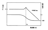
各駆動アンプ36への入力信号に対する各第1の圧電素子17における変位量の周波数特性は、図14に示すように2次系であり、各補償回路60を調整することにより、一般的なサーボ系の安定指標値である位相余裕40度以上とゲイン余裕15dB以上に設定している。
【0065】
実施形態3の前記構成によれば、第1の圧電素子17の印加電圧が比較的大きくても、言い換えるとローラ13の駆動軸10に対する押圧量が大きくても第1のサーボ制御手段62が、目標値となる定電圧回路34の出力信号と、回路の0V(GND)信号と、変形量測定手段55からの出力信号とを比較して目標値に収束するため、図12にて説明した残留変位量Dpを生じなくなる。
【0066】
同様の理由で第2の圧電素子18にも履歴特性がある。そのため大きなリード量を設定した場合、実施形態1で説明した電圧補正手段48による補正動作に時間がかかってしまう。
【0067】
そこで、第2の圧電素子18にも第1の圧電素子17と同様に、図11に示すように第2の圧電素子18の伸縮方向側面に、抵抗値の変化によって、その変形量を検出する歪みゲージなどからなる第2の変形量測定手段65を設け、図15に示すように、D/A変換器39の出力信号を目標値とした図13にて説明した構成と同様の構成とした第2のサーボ制御手段67を設けている。構成の説明については、図13に示す構成と同様であるので省略する。
【0068】
図15に示す構成では、図13に示す構成と同様に、目標値となるD/A変換器39の出力信号と第2の変形量測定手段65からの出力信号を比較して目標値に収束するため、図12にて説明した残変位量Dpが生じなくなる。
【0069】
前記各実施形態では、従動軸16と駆動軸10の押圧調整範囲および交差角度調整範囲は、第1の圧電素子17と第2の圧電素子18の最大伸縮量内に限定されるため、例えば大きなリード設定条件の場合には対応できなくなる。
【0070】
そこで、本発明の実施形態4では大きなリード設定条件に対しても対応できるようにした。実施形態4について図16に基づいて説明する。
【0071】
図16に示すように、ハウジング11における各第1の圧電素子17近傍において、ハウジング11の凹部に従動軸16を押圧する方向に第1の案内部70を設け、この第1の案内部70に略クランク状の第1の調整板71を嵌合し、この第1の調整板71の一端部を第1の圧電素子17に連結し、第1の調整板71の他端部をハウジング11に設けた第1の調整ネジ72によって押圧可能にしており、この構成によって、従動軸16を押圧する方向に螺入される第1の調整ネジ72により、ローラ13における駆動軸10を押圧する方向に対する位置調整が可能になるようにしている。
【0072】
また同様に、各第2の圧電素子18近傍において、ハウジング11の凹部に駆動軸10外周の接線方向に押圧する方向に第2の案内部73を設け、この第2の案内部73に第2の調整板74を嵌合し、この第2の調整板74の一端部が第2の圧電素子18に連結し、第2の調整板74の他端部をハウジング11に設けた第2の調整ネジ75によって押圧可能にしており、この構成によって、駆動軸10外周の接線方向に対する方向に螺入される第2の調整ネジ75により、ローラ13における駆動軸10外周の接線方向に対する押圧位置を調整することが可能になるようにしている。
【0073】
実施形態4の構成によれば、設定する大きなリード条件に対して実施形態1で説明した角度補正動作を行う前に、手動にて第1の調整板71と第2の調整板74とを、第1の調整ネジ72と第2の調整ネジ75とにより、設定リード近傍に位置調整して各第1の圧電素子17と各第2の圧電素子18との最大伸縮量内に入るようにした後に、角度補正動作を行うようにすることができる。
【0074】
実施形態1〜4では、ローラ13の駆動軸10に対する押圧(以降は予圧と称する)力を直接制御せずに、第1の圧電素子17の伸縮量を指令値通りに設定する構成であるが、ローラ13の駆動軸10に対する現在予圧量が定量的に確認することができない。そこで以下の実施形態では、ローラ13の駆動軸10に対する予圧に基づいて制御する構成について説明する。
【0075】
まず、実施形態5について図17,図18に基づいて説明する。
【0076】
第1の出力手段37は、可変電圧回路78と、一方の端子が0Vに接続され、他方の端子に可変電圧回路78の出力信号が入力されて外部信号によりON/OFFする切換スイッチ56を備え、さらに図17に示すように従動軸16を構成する弾性体15aにおける回動支持点部とローラ13の支持部間の外周部に設けられて、当該従動軸16の押圧方向の変形量を検出する変形量測定手段(例えば抵抗値の変化によって、その変形量を検出する歪みゲージなど)79と、切換スイッチ56の出力信号である押圧設定信号と変形量測定手段79の出力信号である現在押圧量とを比較してサーボ制御するサーボ制御手段80を備えた構成になっている。サーボ制御手段80の基本構成は図13にて説明した構成と同様のものである。
【0077】
実施形態5では、各従動軸16に設けたローラ13の駆動軸10への予圧量を、従動軸16の押圧方向の変形量として検出している。この場合、押圧は従動軸16の弾性体15aにおける弾性変形内で行われ、第1の圧電素子17への印加電圧に対する予圧量の関係は線形になることはいうまでもない。
【0078】
さらに実施形態6としては、図19に示すように、第1の出力手段37を、図18に示す実施形態5における可変電圧回路78と切換スイッチ56とに替えて、CPU30(図7参照)に接続されたD/A変換器81をサーボ制御手段80に接続した構成としたものであり、D/A変換器81の出力信号である押圧設定信号と変形量測定手段79の出力信号である現在押圧量とを比較してサーボ制御するようにしている。
【0079】
実施形態6は、角度調整時の押圧開放が、D/A変換器81の出力が0Vとなるデジタルデータを出力する構成であり、例えば適正な予圧設定条件データをROM31(図7参照)に格納されるプログラム内に定数として記述しておけば、適正な予圧を瞬時に設定することができ、ローラ13あるいは駆動軸10の磨耗による経年変化に伴う予圧の再調整作業などを行わなくてよくなる。
【0080】
実施形態6の構成では、各第1の圧電素子17への押圧設定信号が1つしか与えられないため、例えば従動軸16の加工ばらつきなどによって押圧時の変形量にばらつきが生じたり、ブリッジ回路あるいは変形量測定手段79に用いる歪みゲージなどにばらつきがあると、同一の予圧量が得られない場合がある。
【0081】
これを回避する構成として実施形態7を説明する。図20に示す実施形態7の基本構成は図19に示す実施形態6の構成と同様であって、第1の出力手段37を、各第1の圧電素子17への押圧設定信号を独立に与える複数のD/A変換器83と、各D/A変換器83の出力信号である押圧設定信号と各変形量測定手段79の出力信号である現在押圧量とを比較してサーボ制御するサーボ制御手段80とを備えた構成にしている。
【0082】
実施形態7では、例えば従動軸16の押圧量と変形量の関係を予めデータ取りして把握しておき、各々の異なる押圧設定信号を複数のD/A変換器83より出力することができる。
【0083】
【発明の効果】
以上説明したように、本発明に係る摩擦駆動装置によれば、加工,組み付け誤差などによる機械的な位置誤差のために生じる各従動軸と駆動軸とのなす交差角度のばらつきを補正することができるようにしているため、各ローラの軸心と駆動軸とのなす角度が精密に設定され、駆動軸と各従動軸のローラ間でリード誤差によるすべりが発生せず、安定した送り制御を実現することができ、送り精度の向上を図ることができる。
【図面の簡単な説明】
【図1】本発明の実施形態1を説明するための摩擦駆動装置の平面図
【図2】実施形態1の摩擦駆動装置の右側面図
【図3】実施形態1の摩擦駆動装置の一部を断面して示す縦断面図
【図4】実施形態1の図3におけるA−A断面図
【図5】本実施形態におけるローラと駆動軸との関係の説明図
【図6】本実施形態の駆動軸における交差角度とリード量との関係の説明図
【図7】実施形態1における角度調整を行うための制御系の構成を示すブロック図
【図8】実施形態1におけるCPUのコントロールに基づく動作フローに係るフローチャート
【図9】図8の動作フローにおけるサブルーチンのフローチャート
【図10】本発明の実施形態2における従動軸の軸受部分の構成を説明するための断面図
【図11】本発明の実施形態3における駆動軸と従動軸との支持部分を説明するための断面図
【図12】本実施形態に係る圧電素子の印加電圧と変位量との関係を示す図
【図13】実施形態3における第1の圧電素子の変形量制御に係る制御系の構成を示すブロック図
【図14】本実施形態に係る駆動アンプへの入力信号に対する圧電素子における変位量の周波数特性を示す図
【図15】実施形態3における第2の圧電素子の変形量制御に係る制御系の構成を示すブロック図
【図16】本発明の実施形態4における摩擦駆動装置の右側面図
【図17】本発明の実施形態5の摩擦駆動装置における一部を断面して示す縦断面図
【図18】実施形態5における角度調整を行うための制御系の構成を示すブロック図
【図19】実施形態6における角度調整を行うための制御系の構成を示すブロック図
【図20】実施形態7における角度調整を行うための制御系の構成を示すブロック図
【符号の説明】
4 移動体
7 位置検出手段
10 駆動軸
11 ハウジング
12 固定板
13 ローラ
15a 弾性体
15b 剛体
16 従動軸
17 第1の圧電素子
18 第2の圧電素子
22 ロータリーエンコーダ
23 送り駆動モータ
30 CPU
37 第1の出力手段
41 第2の出力手段
42 角度調整手段
46 角度算出手段
47 現在リード量算出手段
48 電圧補正手段
51 ラジアル磁気軸受
54 スラスト磁気軸受
55,65,79 変形量測定手段
70 第1の案内部
71 第1の調整板
72 第1の調整ネジ
73 第2の案内部
74 第2の調整板
75 第2の調整ネジ[0001]
TECHNICAL FIELD OF THE INVENTION
The present invention relates to a friction drive device for moving a moving body forward and backward by rotating a drive shaft, and more particularly to a movement in an optical disc master exposing apparatus having a slide table which is a moving body for accurately exposing a track pitch to an optical disc master. The present invention relates to a friction drive device applied to a body drive unit.
[0002]
[Prior art]
2. Description of the Related Art Conventionally, in a slide table device for exposing an optical disc master, there have been many inventions for realizing high-precision feeding (
[0003]
As a slide table device for exposing an optical disc master, an air slide type slide table device provided with a slide table that can be moved forward and backward via a static pressure bearing is used. For driving the slide table, a voice coil type linear motor is generally used, and a closed loop control system using an interference laser length measuring device or a linear scale as a position detector is employed. In the case of a semiconductor inspection device or the like that requires a stationary state, a ball screw or the like is used to drive the slide table because rigidity in the feed direction is required.
[0004]
With the recent increase in the density of optical discs, an exposure method using an electron beam or the like from a conventional laser beam has emerged in order to achieve higher-resolution exposure. Accurate feeding is required.
[0005]
The twist roller method of the friction drive mechanism can realize a small lead that cannot be obtained with other mechanisms by minimizing the intersection angle between the drive shaft and the driven shaft, and high positioning resolution is expected For this reason, various mechanisms have been proposed in patent documents and non-patent documents as next-generation feed mechanisms.
[0006]
For example, the invention described in
[0007]
The invention described in
[0008]
The invention described in
[0009]
The invention described in
[0010]
[Patent Document 1]
JP-A-2002-25128
[Patent Document 2]
JP-A-2002-92973
[Patent Document 3]
JP 2002-279700 A
[Patent Document 4]
JP-A-8-184360
[Patent Document 5]
JP-A-11-195247
[Patent Document 6]
JP-A-11-195248
[Patent Document 7]
Japanese Patent Publication No. Hei 6-23598
[0011]
[Problems to be solved by the invention]
By the way, in the case of the invention described in
[0012]
This does not pose a problem when the angle between the roller shaft and the drive shaft is large, in other words, when the lead (the distance traveled in the axial direction) is relatively large (for example, several mm). When the angle between the shaft and the shaft is small, in other words, when the lead is small (for example, several hundred μm), if there is a variation in the angle between each roller shaft and the drive shaft, the gap between the drive shaft and the roller of the driven shaft is reduced. In this case, a slip due to a read error occurs, which is a disturbance in closed-loop control, which is not preferable in terms of control, and when applied to exposure of a master optical disc, the track pitch accuracy and the like deteriorate, resulting in a problem in that the exposure quality is unfavorable.
[0013]
Further, in a conventional twist roller type friction drive device, since the driven shaft rotates, there is a problem in supporting the same. The existence of a gap is indispensable for support by sliding contact, and it is impossible to make the rolling element a perfect circle with support by rolling contact. Therefore, there is a problem that the crossing angle of the rollers cannot always be stably maintained. In the invention described in
[0014]
Further, in the invention described in
[0015]
In the invention described in
[0016]
The driving force acting between the drive shaft and one roller in the drive shaft direction is F = μN where μ is the dynamic friction coefficient between the outer periphery of the drive shaft and the roller, and N is the preload. Therefore, the driving force generated around each roller and the outer periphery of the driving shaft also varies, thereby causing the driving force to vary. Therefore, the variation in the angle between the axis of each roller and the driving shaft is synergistic. Then, a slip occurs between the rollers of the drive shaft and the driven shaft, which is a disturbance in closed-loop control, which is not preferable in control.When applied to an optical disk master exposure or the like, track pitch accuracy and the like deteriorate, It is not preferable in terms of exposure quality.
[0017]
SUMMARY OF THE INVENTION It is an object of the present invention to provide a friction drive device which can be applied to an optical disk master exposure apparatus or the like which can realize high-accuracy feeding without the above-mentioned conventional problems.
[0018]
[Means for Solving the Problems]
In order to achieve the above object, an invention according to
[0019]
According to a second aspect of the present invention, in the friction drive device according to the first aspect, the driven shaft is made of a composite material of an elastic body and a rigid body. Installation can be performed easily and reliably.
[0020]
According to a third aspect of the present invention, in the friction drive device according to the first or second aspect, a radial magnetic bearing in which a roller is formed by a repulsive force of a magnet magnetized in a radial direction of the roller, and an axis of the roller Characterized in that it is held on the driven shaft via a thrust magnetic bearing constituted by a repulsive force of a magnet magnetized in the direction, and with this configuration, the roller is driven by the driven shaft via a radial magnetic bearing and a thrust magnetic bearing. Because it is held in a non-contact manner, vibrations generated by rolling elements used in conventional angular bearings and the like are eliminated, stable leads can be performed, stable feed control is possible, and feed accuracy is further improved. Can be.
[0021]
According to a fourth aspect of the present invention, in the friction drive device according to the third aspect, a rare-earth permanent magnet is used as a magnet constituting the radial magnetic bearing and the thrust magnetic bearing. Therefore, a large repulsive force can be obtained, so that the apparatus can be made compact and inexpensive.
[0022]
According to a fifth aspect of the present invention, in the friction drive device according to the first, third or fourth aspect, the driven shaft, the roller, the drive shaft, and the housing are made of a non-magnetic material. In addition, since the magnet can be prevented from attracting to other parts, disturbance to the pressing control and the angle control of the driven shaft can be eliminated, and the feeding accuracy can be further improved.
[0023]
According to a sixth aspect of the present invention, in the friction drive device according to the first aspect, the first output means is turned on / off by a constant voltage circuit, an output signal of the constant voltage circuit being input, and an external signal. A change-over switch, a deformation amount measuring means provided on the first piezoelectric element, and a comparison between a pressing expansion / contraction setting signal which is an output signal of the change-over switch and a current pressing expansion / contraction amount which is an output signal of the deformation amount measuring means. The servo control means performs servo control.This configuration reproduces the pressing (preload) operation of the roller to the outer periphery of the drive shaft and the angle correction operation of correcting the intersection angle between each driven shaft and the drive shaft. Since it can be performed efficiently, stable feed control can be realized and feed accuracy can be improved.
[0024]
According to a seventh aspect of the present invention, in the friction drive device according to the first aspect, a first adjustment plate is provided on the housing so as to be able to press the first piezoelectric element, and the first adjustment plate and the first piezoelectric element are provided. A first adjusting screw via the element enables adjustment of a position of the driven shaft pressed in the outer peripheral direction of the drive shaft, and further, a second adjustment plate is provided on the housing so as to be able to press a second piezoelectric element; The position of the driven shaft in the direction of pressing tangentially on the outer periphery of the drive shaft can be adjusted by a second adjustment screw via the second adjustment plate and the second piezoelectric element. With this configuration, an angle correction operation can be performed even at a large intersection angle, so that stable feed control can be realized in a wide range of read conditions, and versatility as a feed component can be increased. That.
[0025]
According to an eighth aspect of the present invention, in the friction drive device according to the first aspect, the first output means is turned on / off by a variable voltage circuit, an output signal of the variable voltage circuit being input, and an external signal. A changeover switch, and a deformation amount measuring means for detecting a deformation amount in a pressing direction of the driven shaft provided on an outer peripheral portion of the elastic body of the driven shaft; a pressing setting signal which is an output signal of the changeover switch; It is characterized by comprising servo control means for performing servo control by comparing the current pressing amount, which is an output signal, with the preload servo by means of a signal in which the pressing amount of the roller against the drive shaft is replaced by the deformation amount of the driven shaft. In this way, it is possible to instantly set the appropriate pressing conditions, it is easy to readjust the pressing due to aging due to the wear of the rollers or drive shaft, and the reproducibility of the pressing amount when replacing parts Can be like become good, improvement of the assembling property is reduced.
[0026]
According to a ninth aspect of the present invention, in the friction drive device according to the first aspect, the first output unit includes one digital / analog converter, a deformation measuring unit, and an output signal of the digital / analog converter. It is characterized by comprising a servo control means for performing servo control by comparing the pressing setting signal which is the current pressing amount which is the output signal of the deformation amount measuring means, by this configuration, the pressing amount to the drive shaft of the roller Since the pressing servo is performed with the signal replaced with the amount of deformation of the driven shaft, it is possible to instantly set appropriate pressing conditions, and it is easy to readjust the pressing due to aging due to wear of the roller or drive shaft, and parts It is possible to improve the assemblability, for example, the reproducibility of the pressing amount at the time of replacement is improved.
[0027]
According to a tenth aspect of the present invention, in the friction drive device according to the first aspect, a plurality of digital / analog converters each independently providing a first output unit with a pressure setting signal to the first piezoelectric element, An amount measuring unit, and a servo control unit that performs servo control by comparing a pressing setting signal that is an output signal of the plurality of digital / analog converters with a current pressing amount that is an output signal of the deformation amount measuring unit. According to this configuration, the pressing servo is performed with a signal obtained by replacing the pressing amount of the roller against the driving shaft with the deformation amount of the driven shaft, and the pressing set value to each pressing unit is independently given. There is no variation in the driving force generated on the outer circumference of each roller and the drive shaft, and stable feed operation can be realized even with long stroke drive, and feed control accuracy and assemblability can be improved. .
[0028]
According to an eleventh aspect of the present invention, in the friction drive device according to the first aspect, the second output means is a digital / analog converter, a deformation measuring means provided on a second piezoelectric element, and the digital / analog converter. It is characterized by comprising servo control means for performing a servo operation by comparing a pressing / contracting setting signal which is an output signal of an analog converter and a current pressing / contracting amount which is an output signal of the deformation amount measuring means. , The roller presses (preloads) the outer circumference of the drive shaft, and the angle correction operation that corrects the intersection angle between each driven shaft and the drive shaft can be performed with good reproducibility, thus achieving stable feed control and improving feed accuracy. Can be achieved.
[0029]
BEST MODE FOR CARRYING OUT THE INVENTION
Hereinafter, embodiments of the present invention will be described with reference to the drawings.
[0030]
FIG. 1 is a plan view of a friction drive device for explaining
[0031]
As shown in FIG. 2, a
[0032]
In this example, the position detecting means 7 comprises a
[0033]
As shown in FIGS. 3 and 4, a
[0034]
As shown in FIG. 4, one end (the right end in FIG. 3) of the driven
[0035]
As shown in FIG. 3, the right end of the
[0036]
Further, the
[0037]
On the other hand, the outer periphery of the stepped portion 10c at the left end of the
[0038]
In the first embodiment of the above configuration, an appropriate energizing voltage is applied to the second
[0039]
Further, the moving amount L (the amount of lead) by which the
[0040]
(Equation 1)
L = π · D · sin θ ≒ π · D · θ
θ = sin -1 {L / (π · D)}
For example, the relationship between the intersection angle and the lead amount L when D = 30 mm is linear as shown in the log-log graph of FIG.
[0041]
Next, a control system for adjusting the angle of the driven
[0042]
A CPU (central processing unit) 30 to which a Z-phase pulse signal 28 generated once in one round of the
[0043]
Further, the
[0044]
The output signal of the
[0045]
In the first embodiment, the angle adjusting means 42 is constituted by the entire structure shown in FIG.
[0046]
An operation flow based on the control of the
[0047]
The
[0048]
9, digital data corresponding to the intersection angle θ (see FIG. 5) calculated by the angle calculation means 46 is output to the D / A converter 39 (S 5). Then, a displacement voltage corresponding to the calculated intersection angle θ is applied to the second
[0049]
In the above state, the
[0050]
If the difference data ΔLi is equal to or smaller than the preset allowable error data ε (Yes in S10), the angle data θi is stored in the RAM 32 (S11). On the other hand, when the difference data ΔLi is larger than 0 when the difference is larger (No in S10), the calculated angle data is sequentially increased by a minute amount Δθh set to, for example, the minimum resolution of the D / A converter 39 ( S12) If ΔLi is smaller than 0, the calculated angle data is sequentially reduced by a small amount Δθh (S13). This operation is repeatedly performed by the voltage correction means 48 provided in the
[0051]
The operation flow is a subroutine. In FIG. 7, the operation is sequentially performed for each
[0052]
Here, the
[0053]
According to the configuration of the first embodiment, even if the intersection angle formed between the driven
[0054]
FIG. 10 is a cross-sectional view illustrating a configuration of a bearing portion of a driven shaft according to
[0055]
In FIG. 10, the center outer periphery of a
[0056]
In the bearing structure, since the
[0057]
If the magnet in the second embodiment is formed of a rare-earth permanent magnet, the rare-earth permanent magnet is a small-sized magnet that can provide a large repulsion force, and thus the device can be made small.
[0058]
In the second embodiment, the components of the driven
[0059]
FIG. 11 is a cross-sectional view showing a cross-sectional state similar to FIG. 4 for explaining a supporting portion of a drive shaft and a driven shaft in
[0060]
The relationship between the applied voltage and the amount of displacement of the first
[0061]
Therefore, in the third embodiment, as shown in FIG. 11, deformation amount measuring means 55 such as a strain gauge for detecting the deformation amount by, for example, a change in resistance value is provided on the side surface of each first
[0062]
FIG. 13 is a block diagram showing a configuration of a control system for controlling the amount of deformation of each first
[0063]
Further, the output signal of the
[0064]
The frequency characteristic of the displacement amount in each first
[0065]
According to the configuration of the third embodiment, even if the voltage applied to the first
[0066]
For the same reason, the second
[0067]
Therefore, similarly to the first
[0068]
In the configuration shown in FIG. 15, similarly to the configuration shown in FIG. 13, the output signal of the D /
[0069]
In each of the above embodiments, the pressing adjustment range and the intersection angle adjustment range of the driven
[0070]
Therefore, the fourth embodiment of the present invention can cope with a large read setting condition.
[0071]
As shown in FIG. 16, near the first
[0072]
Similarly, in the vicinity of each second
[0073]
According to the configuration of the fourth embodiment, before performing the angle correction operation described in the first embodiment with respect to a large lead condition to be set, the
[0074]
The first to fourth embodiments have a configuration in which the amount of expansion and contraction of the first
[0075]
First, a fifth embodiment will be described with reference to FIGS.
[0076]
The first output means 37 includes a
[0077]
In the fifth embodiment, the amount of preload of the
[0078]
Further, as a sixth embodiment, as shown in FIG. 19, the CPU 30 (see FIG. 7) replaces the first output means 37 with the
[0079]
The sixth embodiment is configured to output digital data such that the output of the D /
[0080]
In the configuration of the sixth embodiment, since only one pressing setting signal to each first
[0081]
[0082]
In the seventh embodiment, for example, the relationship between the amount of pressing and the amount of deformation of the driven
[0083]
【The invention's effect】
As described above, according to the friction drive device of the present invention, it is possible to correct the variation of the intersection angle between each driven shaft and the drive shaft caused by a mechanical position error due to a machining or assembly error. Because the angle between the axis of each roller and the drive shaft is precisely set, there is no slippage between the rollers of the drive shaft and each driven shaft due to lead error, and stable feed control is achieved. And the feed accuracy can be improved.
[Brief description of the drawings]
FIG. 1 is a plan view of a friction drive device for describing
FIG. 2 is a right side view of the friction drive device according to the first embodiment.
FIG. 3 is a vertical cross-sectional view showing a part of the friction drive device according to the first embodiment;
FIG. 4 is a sectional view taken along line AA in FIG. 3 of the first embodiment.
FIG. 5 is an explanatory diagram of a relationship between a roller and a drive shaft in the embodiment.
FIG. 6 is an explanatory diagram of a relationship between an intersection angle and a lead amount on a drive shaft according to the embodiment.
FIG. 7 is a block diagram illustrating a configuration of a control system for performing angle adjustment according to the first embodiment.
FIG. 8 is a flowchart illustrating an operation flow based on control of a CPU according to the first embodiment.
FIG. 9 is a flowchart of a subroutine in the operation flow of FIG. 8;
FIG. 10 is a cross-sectional view illustrating a configuration of a bearing portion of a driven shaft according to a second embodiment of the present invention.
FIG. 11 is a cross-sectional view illustrating a support portion of a drive shaft and a driven shaft according to a third embodiment of the present invention.
FIG. 12 is a diagram showing a relationship between an applied voltage and a displacement amount of the piezoelectric element according to the embodiment.
FIG. 13 is a block diagram showing a configuration of a control system related to deformation amount control of a first piezoelectric element in a third embodiment.
FIG. 14 is a diagram showing a frequency characteristic of a displacement amount in the piezoelectric element with respect to an input signal to the drive amplifier according to the embodiment;
FIG. 15 is a block diagram showing a configuration of a control system for controlling the amount of deformation of a second piezoelectric element according to a third embodiment.
FIG. 16 is a right side view of a friction drive device according to a fourth embodiment of the present invention.
FIG. 17 is a vertical cross-sectional view showing a part of a friction drive device according to a fifth embodiment of the present invention;
FIG. 18 is a block diagram illustrating a configuration of a control system for performing angle adjustment according to a fifth embodiment.
FIG. 19 is a block diagram showing a configuration of a control system for performing angle adjustment in a sixth embodiment.
FIG. 20 is a block diagram illustrating a configuration of a control system for performing angle adjustment according to a seventh embodiment.
[Explanation of symbols]
4 Moving body
7 Position detection means
10 Drive shaft
11 Housing
12 Fixing plate
13 rollers
15a elastic body
15b rigid body
16 driven shaft
17 First piezoelectric element
18 Second piezoelectric element
22 Rotary encoder
23 Feed drive motor
30 CPU
37. First Output Means
41 Second output means
42 Angle adjusting means
46 Angle calculation means
47 Current lead amount calculation means
48 Voltage correction means
51 Radial magnetic bearing
54 Thrust Magnetic Bearing
55, 65, 79 Deformation amount measuring means
70 First Guide
71 First adjustment plate
72 First adjustment screw
73 Second Guide
74 Second adjustment plate
75 Second adjustment screw
Claims (11)
前記従動軸の一端を前記ハウジングにより支持し、かつ他端を前記ローラが前記駆動軸の外周に押圧する方向に伸縮する第1の圧電素子および前記駆動軸の外周における接線方向に押圧する方向に伸縮する第2の圧電素子を介して前記ハウジングにより支持し、さらに前記第1の圧電素子への印加電圧を制御する第1の出力手段と、送りの設定リード量に対して前記従動軸の傾き角度を算出する角度算出手段と、算出された算出角度に相当する出力電圧を第2の圧電素子に印加する第2の出力手段と、前記駆動軸を回転駆動する送り駆動モータの回転角度を検出するロータリーエンコーダにおける1回転当たりの原点検出信号および前記位置検出手段の位置検出信号に基づいて現在リード量を算出する現在リード量算出手段と、現在リード量と設定リード量を比較して前記第2の圧電素子への印加電圧を増減する電圧補正手段とを具備した角度調整手段を備えたことを特徴とする摩擦駆動装置。A roller provided on a plurality of driven shafts having rolling axes that are in rolling contact with the drive shaft and the outer periphery thereof and having a small crossing angle with respect to the drive shaft, and the roller with respect to the drive shaft. A housing that is circumscribed and that is axially moved by an axial component of frictional force generated by the roller due to the rotation of the drive shaft, a moving body that moves with the housing, A friction drive device comprising: a guide mechanism that guides in the axial direction of a drive shaft; and a position detection unit that detects a feed position of the moving body.
One end of the driven shaft is supported by the housing, and the other end is a first piezoelectric element that expands and contracts in a direction in which the roller presses the outer periphery of the drive shaft, and a direction in which the other end presses in a tangential direction on the outer periphery of the drive shaft. First output means for supporting the housing via a second piezoelectric element which expands and contracts, and further controlling a voltage applied to the first piezoelectric element; and inclination of the driven shaft with respect to a set lead amount for feeding. Angle calculating means for calculating an angle, second output means for applying an output voltage corresponding to the calculated calculated angle to the second piezoelectric element, and detecting a rotation angle of a feed drive motor for rotating the drive shaft. Current lead amount calculating means for calculating a current lead amount based on an origin detection signal per rotation of the rotary encoder and a position detection signal of the position detecting means; Friction drive, characterized in that by comparing the set read amount with the angle adjusting means comprises a voltage correction means for increasing or decreasing the voltage applied to the second piezoelectric element.
Priority Applications (1)
| Application Number | Priority Date | Filing Date | Title |
|---|---|---|---|
| JP2002368304A JP4101634B2 (en) | 2002-12-19 | 2002-12-19 | Friction drive |
Applications Claiming Priority (1)
| Application Number | Priority Date | Filing Date | Title |
|---|---|---|---|
| JP2002368304A JP4101634B2 (en) | 2002-12-19 | 2002-12-19 | Friction drive |
Publications (2)
| Publication Number | Publication Date |
|---|---|
| JP2004197864A true JP2004197864A (en) | 2004-07-15 |
| JP4101634B2 JP4101634B2 (en) | 2008-06-18 |
Family
ID=32764908
Family Applications (1)
| Application Number | Title | Priority Date | Filing Date |
|---|---|---|---|
| JP2002368304A Expired - Fee Related JP4101634B2 (en) | 2002-12-19 | 2002-12-19 | Friction drive |
Country Status (1)
| Country | Link |
|---|---|
| JP (1) | JP4101634B2 (en) |
Cited By (4)
| Publication number | Priority date | Publication date | Assignee | Title |
|---|---|---|---|---|
| JP2006320118A (en) * | 2005-05-13 | 2006-11-24 | Nippon Pulse Motor Co Ltd | Composite drive unit |
| JP2008249061A (en) * | 2007-03-30 | 2008-10-16 | Ricoh Co Ltd | Friction drive mechanism |
| CN112600766A (en) * | 2020-12-10 | 2021-04-02 | 西藏瀚森科技发展有限公司 | Switch with distributed hybrid structure for network engineering |
| CN115566930A (en) * | 2022-11-10 | 2023-01-03 | 吉林大学 | Large-stroke piezoelectric actuator capable of outputting continuous angular displacement |
-
2002
- 2002-12-19 JP JP2002368304A patent/JP4101634B2/en not_active Expired - Fee Related
Cited By (6)
| Publication number | Priority date | Publication date | Assignee | Title |
|---|---|---|---|---|
| JP2006320118A (en) * | 2005-05-13 | 2006-11-24 | Nippon Pulse Motor Co Ltd | Composite drive unit |
| JP4761242B2 (en) * | 2005-05-13 | 2011-08-31 | 日本パルスモーター株式会社 | Compound drive |
| JP2008249061A (en) * | 2007-03-30 | 2008-10-16 | Ricoh Co Ltd | Friction drive mechanism |
| CN112600766A (en) * | 2020-12-10 | 2021-04-02 | 西藏瀚森科技发展有限公司 | Switch with distributed hybrid structure for network engineering |
| CN112600766B (en) * | 2020-12-10 | 2022-07-15 | 西藏瀚森科技发展有限公司 | Switch with distributed hybrid structure for network engineering |
| CN115566930A (en) * | 2022-11-10 | 2023-01-03 | 吉林大学 | Large-stroke piezoelectric actuator capable of outputting continuous angular displacement |
Also Published As
| Publication number | Publication date |
|---|---|
| JP4101634B2 (en) | 2008-06-18 |
Similar Documents
| Publication | Publication Date | Title |
|---|---|---|
| US6446339B2 (en) | Preloading method for preload-adjustable rolling bearing | |
| US5341569A (en) | Preloading method for preload-adjustable rolling bearing and manufacturing method of the same | |
| US6712518B2 (en) | Preloading method for preload-adjustable rolling bearing and manufacture of the same | |
| JP5468379B2 (en) | Bearing device and swing arm assembly for magnetic disk | |
| US5863136A (en) | Method of reducing axial runout of a rolling bearing unit and a rolling bearing unit in which axial runout has been reduced | |
| JPH11320295A (en) | Manufacture of double row rolling bearing device loaded with pre-load | |
| JP4082558B2 (en) | Friction drive | |
| JP4101634B2 (en) | Friction drive | |
| JP3707805B2 (en) | Positioning device | |
| JP3254825B2 (en) | Manufacturing method of rolling bearing device to which preload is applied | |
| JP2000176761A (en) | Vertical axis linear motion mechanism | |
| JP4992182B2 (en) | Axial fine movement device with rotating mechanism | |
| JP4113727B2 (en) | Friction drive | |
| JP4413498B2 (en) | Friction drive | |
| JP2007192358A (en) | Axial fine-movement mechanism with rotating mechanism, rough and fine-movement positioning device, method of installing axial fine-movement mechanism with rotating mechanism, and method of installing rough and fine movement positioning device | |
| JP2003308122A (en) | Friction driving device | |
| CN109027161B (en) | Mechanical nanometer-level high-precision linear driving device | |
| JP4861229B2 (en) | Friction drive | |
| JP2003343676A (en) | Friction driving device | |
| JPH1113755A (en) | Rolling bearing device applied with pre-load | |
| JPH08184360A (en) | Frictional forward and backward movement drive device | |
| JP2003056559A (en) | Roller bearing device provided with pre-load | |
| JP5273270B2 (en) | Axial fine movement mechanism with rotation mechanism and positioning device using the same | |
| JP5067487B2 (en) | Positioning device | |
| JP2007193663A (en) | Axial direction slight movement mechanism with rotary mechanism, and coarse and fine movement positioning apparatus |
Legal Events
| Date | Code | Title | Description |
|---|---|---|---|
| A621 | Written request for application examination |
Free format text: JAPANESE INTERMEDIATE CODE: A621 Effective date: 20050314 |
|
| TRDD | Decision of grant or rejection written | ||
| A977 | Report on retrieval |
Free format text: JAPANESE INTERMEDIATE CODE: A971007 Effective date: 20080314 |
|
| A01 | Written decision to grant a patent or to grant a registration (utility model) |
Free format text: JAPANESE INTERMEDIATE CODE: A01 Effective date: 20080318 |
|
| A61 | First payment of annual fees (during grant procedure) |
Free format text: JAPANESE INTERMEDIATE CODE: A61 Effective date: 20080319 |
|
| FPAY | Renewal fee payment (event date is renewal date of database) |
Free format text: PAYMENT UNTIL: 20110328 Year of fee payment: 3 |
|
| R150 | Certificate of patent or registration of utility model |
Free format text: JAPANESE INTERMEDIATE CODE: R150 |
|
| FPAY | Renewal fee payment (event date is renewal date of database) |
Free format text: PAYMENT UNTIL: 20120328 Year of fee payment: 4 |
|
| FPAY | Renewal fee payment (event date is renewal date of database) |
Free format text: PAYMENT UNTIL: 20130328 Year of fee payment: 5 |
|
| FPAY | Renewal fee payment (event date is renewal date of database) |
Free format text: PAYMENT UNTIL: 20140328 Year of fee payment: 6 |
|
| LAPS | Cancellation because of no payment of annual fees |