JP2004196548A - Object conveying system and conveying method - Google Patents
Object conveying system and conveying method Download PDFInfo
- Publication number
- JP2004196548A JP2004196548A JP2003073624A JP2003073624A JP2004196548A JP 2004196548 A JP2004196548 A JP 2004196548A JP 2003073624 A JP2003073624 A JP 2003073624A JP 2003073624 A JP2003073624 A JP 2003073624A JP 2004196548 A JP2004196548 A JP 2004196548A
- Authority
- JP
- Japan
- Prior art keywords
- robot
- article
- articles
- sensor
- storage means
- Prior art date
- Legal status (The legal status is an assumption and is not a legal conclusion. Google has not performed a legal analysis and makes no representation as to the accuracy of the status listed.)
- Granted
Links
Images


Classifications
-
- G—PHYSICS
- G06—COMPUTING; CALCULATING OR COUNTING
- G06T—IMAGE DATA PROCESSING OR GENERATION, IN GENERAL
- G06T1/00—General purpose image data processing
- G06T1/0014—Image feed-back for automatic industrial control, e.g. robot with camera
-
- B—PERFORMING OPERATIONS; TRANSPORTING
- B25—HAND TOOLS; PORTABLE POWER-DRIVEN TOOLS; MANIPULATORS
- B25J—MANIPULATORS; CHAMBERS PROVIDED WITH MANIPULATION DEVICES
- B25J19/00—Accessories fitted to manipulators, e.g. for monitoring, for viewing; Safety devices combined with or specially adapted for use in connection with manipulators
- B25J19/02—Sensing devices
- B25J19/021—Optical sensing devices
-
- B—PERFORMING OPERATIONS; TRANSPORTING
- B25—HAND TOOLS; PORTABLE POWER-DRIVEN TOOLS; MANIPULATORS
- B25J—MANIPULATORS; CHAMBERS PROVIDED WITH MANIPULATION DEVICES
- B25J9/00—Programme-controlled manipulators
- B25J9/0084—Programme-controlled manipulators comprising a plurality of manipulators
-
- B—PERFORMING OPERATIONS; TRANSPORTING
- B25—HAND TOOLS; PORTABLE POWER-DRIVEN TOOLS; MANIPULATORS
- B25J—MANIPULATORS; CHAMBERS PROVIDED WITH MANIPULATION DEVICES
- B25J9/00—Programme-controlled manipulators
- B25J9/16—Programme controls
- B25J9/1679—Programme controls characterised by the tasks executed
- B25J9/1682—Dual arm manipulator; Coordination of several manipulators
-
- B—PERFORMING OPERATIONS; TRANSPORTING
- B25—HAND TOOLS; PORTABLE POWER-DRIVEN TOOLS; MANIPULATORS
- B25J—MANIPULATORS; CHAMBERS PROVIDED WITH MANIPULATION DEVICES
- B25J9/00—Programme-controlled manipulators
- B25J9/16—Programme controls
- B25J9/1694—Programme controls characterised by use of sensors other than normal servo-feedback from position, speed or acceleration sensors, perception control, multi-sensor controlled systems, sensor fusion
- B25J9/1697—Vision controlled systems
-
- G—PHYSICS
- G05—CONTROLLING; REGULATING
- G05B—CONTROL OR REGULATING SYSTEMS IN GENERAL; FUNCTIONAL ELEMENTS OF SUCH SYSTEMS; MONITORING OR TESTING ARRANGEMENTS FOR SUCH SYSTEMS OR ELEMENTS
- G05B2219/00—Program-control systems
- G05B2219/30—Nc systems
- G05B2219/40—Robotics, robotics mapping to robotics vision
- G05B2219/40053—Pick 3-D object from pile of objects
-
- G—PHYSICS
- G05—CONTROLLING; REGULATING
- G05B—CONTROL OR REGULATING SYSTEMS IN GENERAL; FUNCTIONAL ELEMENTS OF SUCH SYSTEMS; MONITORING OR TESTING ARRANGEMENTS FOR SUCH SYSTEMS OR ELEMENTS
- G05B2219/00—Program-control systems
- G05B2219/30—Nc systems
- G05B2219/40—Robotics, robotics mapping to robotics vision
- G05B2219/40306—Two or more independent robots
-
- Y—GENERAL TAGGING OF NEW TECHNOLOGICAL DEVELOPMENTS; GENERAL TAGGING OF CROSS-SECTIONAL TECHNOLOGIES SPANNING OVER SEVERAL SECTIONS OF THE IPC; TECHNICAL SUBJECTS COVERED BY FORMER USPC CROSS-REFERENCE ART COLLECTIONS [XRACs] AND DIGESTS
- Y02—TECHNOLOGIES OR APPLICATIONS FOR MITIGATION OR ADAPTATION AGAINST CLIMATE CHANGE
- Y02P—CLIMATE CHANGE MITIGATION TECHNOLOGIES IN THE PRODUCTION OR PROCESSING OF GOODS
- Y02P90/00—Enabling technologies with a potential contribution to greenhouse gas [GHG] emissions mitigation
- Y02P90/02—Total factory control, e.g. smart factories, flexible manufacturing systems [FMS] or integrated manufacturing systems [IMS]
Landscapes
- Engineering & Computer Science (AREA)
- Robotics (AREA)
- Mechanical Engineering (AREA)
- Physics & Mathematics (AREA)
- General Physics & Mathematics (AREA)
- Theoretical Computer Science (AREA)
- Manipulator (AREA)
Abstract
Description
【0001】
【発明の属する技術分野】
ロボットを用いて、搬送対象の部品や加工品等を搬送する物品搬送システム及び搬送方法に関する。
【0002】
【従来の技術】
所定位置に供給された部品や加工品等の物品をロボットが把持し、次の工程に引き渡すようにした作業はハンドリングロボットとして周知である。
又、パレットやカゴなどの収容手段に収納されている整列されていない物品を1台の視覚センサを装着したロボットが、該視覚センサによって物品の位置、姿勢を検出し、この検出した位置姿勢に基いて、ロボットのハンドの位置姿勢を制御して、検出した物品を把持し取り出し、次の工程に搬送し引き渡すようにしたシステムも実現されている(例えば、特許文献1参照)。
【0003】
この場合は、ロボットに視覚センサを備えるとしても、パレットやカゴなどの収容手段内の物品の位置、姿勢を検出するものであり、収容手段の位置を検出するものではない。パレットやカゴ等の物品が収納された収容手段は、センサを装着したロボットの動作領域内の決まった場所に位置決めして載置されなければならない。しかも、収容手段内の物品が空となった場合には、新たな物品が収納された収容手段と入れ替えねばならない。
【0004】
又、逆にパレットやカゴなどの収容手段内にロボットにより物品を収容する場合においても、位置決めされた収容手段に対してロボットに装着された視覚センサにより、物品のない場所、最上段の物品の高さなどの情報を検出しこの情報に基いて、ロボットのハンドで把持してきた物品を収容手段内に詰め込む作業が行われている。この場合も、収容手段内に物品が満杯になると、この収容手段を運び出し、新たな空の収容手段を所定位置に位置決めする必要がある。
【0005】
【特許文献1】
特開2000−288974号公報
【0006】
【発明が解決しようとする課題】
パレットやカゴ等の収容手段に収納された物品をロボットによって取り出す際、又は収容手段に物品を格納する際、収容手段は所定位置に位置決めされて載置されている。しかも、この位置はロボットの作動領域内でなければならない。かつ、この取り出した物品を次の工程に引き渡す位置もロボットの作動領域内でなければならない。そのため、ロボットと次の工程に用いる機械は近接して配置しなければならない。例えば、機械加工におけるワークの搬送システムにおいては、加工機とロボットを近接して配置する必要があり、かつ、加工機、及びロボットの周辺機器もこのロボット及び加工機の周辺に配置しなければならない。しかも、ロボットや工作機械に作業員がアクセスするアクセススペースも確保する必要がある。その結果、比較的狭い領域内に混み合ったシステム構成を構築せざるをえない。
【0007】
従って、ロボットの作動領域内に多くの収容手段を配置することは難しい。又、長時間稼動のためには、ロボットに物品を供給する場合には、収容手段が空になると、物品が収容されている新たな収容容器を供給しなければならない。又、ロボットから供給される物品を収容する場合には、収容容器が満杯になると、空の収容手段を供給しなければならない。そのため、コンベア等で連続的に収容手段を供給することは大きなスペースを占めることになり好ましくはない。
そこで、本発明は、狭い領域内に種々の装置が配置され込み入った領域においても、ロボットによる物品の搬送が容易にできる物品搬送システム、搬送方法を提供することにある。
【0008】
【課題を解決するための手段】
請求項1から請求項11に係わる発明は、収容手段から物品を取り出し搬送する物品搬送システムに関するものであり、請求項1に係わる発明は、位置決めされた物品が収納された収容手段を取り出し、第2ロボットの稼動範囲内の所定位置に該収容手段を保持したまま位置決めする第1ロボットと、該第1ロボットで保持された前記収容手段に収容されている物品を取り出し次の工程へ搬送する第2ロボットとを備え、これら2台のロボットによって、物品を搬送するようにしたものである。さらに、請求項2に係わる発明は、物品が山積みされて収容手段に収容されているような場合にも対応できるように、第2ロボットにセンサを備え、該センサにより、第1ロボットで保持された前記収容手段に入っている物品の位置及び/または姿勢をセンサで認識し物品を取り出し次の工程へ搬送するようにしたものである。請求項3,4に係わる発明は、第2ロボットが物品を取り出す際やセンサで物品の位置及び/または姿勢を認識する際に、第1ロボットは把持した前記収容手段の位置及び/または姿勢を移動させることにより、物品の位置、姿勢の認識、物品の取り出しを容易にしたものである。又、請求項5に係わる発明は、第1ロボットにもセンサを装着し、該センサにより検出した前記収容手段の位置に基いて第1ロボットが前記収容手段を把持するようにしたものである。
【0009】
又、収容手段に収容された物品が取り出された際に、請求項6に係わる発明は、物品の取り出された個数もしくは残りの物品の個数を該システムの外へ出力するようにし、請求項7に係わる発明は、取り出された物品の個数もしくは残りの物品の個数が、別に設定されている比較条件を満たした際に該システムの外へ信号を出力するようにし、請求項8に係わる発明は、第2ロボットが、物品を把持したことを第1ロボットへ知らせるようにした。さらに、請求項9に係わる発明は、第2ロボットが物品を取り出す際に、第2ロボットが、物品を把持したこと、もしくは次工程の準備を開始すべき領域に達したことを次の工程へ知らせるようにした。
又、請求項10に係わる発明は、第2ロボットが取り出した物品を搬送する次の工程が、物品を一時保持する仮置き台への搬送としたものである。さらに、請求項11に係わる発明は、第2ロボットが収容手段から物品を取り出す際に、何らかの異常が発生し、第2ロボットのみでは異常を解除できない場合に、収容手段を把持している第1ロボットが、収容手段の位置及び/又は姿勢を移動させることで、第2ロボットの異常解除を補助するようにしたものである。
【0010】
請求項12から請求項21に係わる発明は、収容手段に物品を収容して搬送する搬送システムに関するものであり、請求項12に係わる発明は、前の工程から物品を取り出し、第1ロボットが把持している収容手段の中へ、設定所定パターンで物品を順次載置する第2ロボットと、前記収容手段を保持し、物品が収容された前記収容手段を所定の位置に搬送する第1ロボットとを備えるものである。又、請求項13に係わる発明は、第2ロボットにセンサを備え、前の工程から物品を取り出し、第1ロボットで把持され、かつ位置決めされた収容手段の中へ、前記センサによって置くべき位置を認識して載置し、第1ロボットが、収容手段を保持し、物品の収容された前記収容手段を所定の位置に搬送するようにしたものである。又、請求項14,15に係わる発明は、第2ロボットが物品を前記収容手段に入れる際やセンサで物品を置くべき位置を認識する際に、第1ロボットが該収容手段の位置及び/または姿勢を移動させることにより、物品を置くべき位置の認識と、物品の収容を容易にしたものである。さらに、請求項16に係わる発明は、第1ロボットにもセンサを装着し、第1ロボットが該収容手段を所定の位置に搬送する際に、該収容手段の格納位置を該センサにより認識して格納するようにしたものである。
【0011】
又、収容手段に物品を入れる際に、請求項17に係わる発明は、入れた物品の個数もしくは残りの物品の個数を該システムの外へ出力するようにし、請求項18に係わる発明は、入れた物品の個数もしくは残りの物品の個数が、別に設定されている比較条件を満たした際に該システムの外へ信号を出力するようにし、請求項19に係わる発明は、第2ロボットが物品を入れる際に、第2ロボットが、物品の格納を完了したことを第1ロボットへ知らせるようにした。
【0012】
請求項20に係わる発明は、第1ロボットが把持する収容手段へ入れるために、第2ロボットが物品を取り出してくる前工程が、物品を一時保持する仮置き台から取り出す工程とした。又、請求項21に係わる発明は、第2ロボットが収容手段へ物品を入れる際に、何らかの異常が発生し、第2ロボットのみでは異常を解除できない場合に、収容手段を把持している第1ロボットが、収容手段の位置及び/又は姿勢を移動させることで、第2ロボットの異常解除を補助するようにした。
さらに、請求項22,請求項23に係わる発明は、前述した各搬送システムにおいて使用されるセンサを視覚センサ又は3次元位置センサとしたものである。
請求項24から請求項34に係わる発明は、上述した請求項1〜11に係わる発明の搬送システムが実施する搬送方法に関するものである。請求項24に係わる発明は、第1のロボットにより、位置決めされた物品が収納された収容手段を取り出し、第2ロボットの稼動範囲内の所定位置に該収容手段を保持したまま位置決めする段階と、第2ロボットが前記収容手段に収容されている物品を取り出し次の工程へ搬送する段階で構成される物品搬送方法である。又、請求項25に係わる発明は、第1ロボットにより、物品が収容された収容手段を取り出し、第2ロボットの稼動範囲内の所定位置に該収容手段を保持したまま位置決めする段階と、該第2ロボットが該第2ロボットに備えるセンサにより前記収容手段に入っている物品の位置及び/または姿勢をセンサで認識し物品を取り出し次の工程へ搬送する段階で構成されるものである。さらに、請求項26,27に係わる発明は、第2ロボットが物品を取り出す際やセンサで物品の位置及び/または姿勢を認識する際に、第1ロボットが把持した前記収容手段の位置または姿勢を移動させる段階を含むものとした。また、請求項28に係わる発明は、第1ロボットにセンサを装着し、該センサにより検出した前記収容手段の位置に基いて、第1ロボットが前記収容手段を把持する段階を含むものとした。
【0013】
又、収容手段に収容された物品が取り出された際に、請求項29に係わる発明は、物品の取り出された個数もしくは残りの物品の個数を該系の外へ出力するようにし、請求項30に係わる発明は、取り出された物品の個数もしくは残りの物品の個数が、別に設定されている比較条件を満たした際に該系の外へ信号を出力するようにし、請求項31に係わる発明は、第2ロボットが、物品を把持したことを第1ロボットへ知らせるようにし、請求項32に係わる発明は、第2ロボットが、物品を把持したこと、もしくは次工程の準備を開始すべき領域に達したことを次の工程へ知らせるようにした。
【0014】
請求項33に係わる発明は、第2ロボットが取り出した物品を搬送する次の工程へ搬送する段階が、物品を一時保持する仮置き台への搬送である段階を含むものとした。請求項34に係わる発明は、第2ロボットが収容手段から物品を取り出す際に、何らかの異常が発生し、第2ロボットのみでは異常を解除できない場合に、収容手段を把持している第1ロボットが、収容手段の位置及び/又は姿勢を移動させることで、第2ロボットの異常解除を補助する段階を含むものとした。
【0015】
請求項35から請求項44に係わる発明は、上述した請求項12〜21に係わる発明の搬送システムが実施する搬送方法に関するものである。請求項35に係わる発明は、第2ロボットが前の工程から物品を取り出し、第1ロボットが把持している収容手段の中へ、設定所定パターンで物品を順次載置する段階と、保持した前記収容手段に所定量の物品が収容されると、前記第1ロボットが前記収容手段を所定の位置に搬送する段階により構成される物品搬送方法である。また請求項36に係わる発明は、第2ロボットが前の工程から物品を取り出し、第1ロボットが把持している収容手段に、第2ロボットが有するセンサによって置くべき位置を認識して載置する段階と、保持した前記収容手段に所定量の物品が収容されると、前記第1ロボットが前記収容手段を所定の位置に搬送する段階を含むものである。請求項37,38に係わる発明は、第2ロボットが物品を前記収容手段に入れる際やセンサで物品を置くべき位置を認識する際に、第1ロボットが該収容手段の位置及び/または姿勢を移動させる段階を含むものである。請求項39に係わる発明は、第1ロボットにもセンサを装着し、第1ロボットが前記収容手段を所定の位置に搬送する際に、該収容手段の格納位置を該センサにより認識して格納する段階を含むものである。
又、収容手段に物品を入れる際に、請求項40に係わる発明は、収容手段に物品を入れる際に、入れた物品の個数もしくは残りの物品の個数を該系の外へ出力するようにし、請求項41に係わる発明は、入れた物品の個数もしくは残りの物品の個数が、別に設定されている比較条件を満たした際に該系の外へ信号を出力するようにし、請求項42に係わる発明は、第2ロボットが、物品の格納を完了したことを第1ロボットへ知らせるようにした。
【0016】
請求項43に係わる発明は、第1ロボットが把持する収容手段へ入れるために、第2ロボットが物品を取り出してくる前の段階が、物品を一時保持する仮置き台から取り出す段階を含むものとした。請求項44に係わる発明は、第2ロボットが収容手段へ物品を入れる際に、何らかの異常が発生し、第2ロボットのみでは異常を解除できない場合に、収容手段を把持している第1ロボットが、収容手段の位置及び/又は姿勢を移動させることで、第2ロボットの異常解除を補助する段階を含むものとした。
又、請求項45,請求項46に係わる発明は、上述した各搬送方法で使用されるセンサを視覚センサ又は、3次元位置センサとしたものである。
【0017】
【発明の実施の形態】
図1は、本発明の物品搬送システム及び物品搬送方法の各実施形態の全体構成を示す。2台のロボット30と、ロボット1によって、棚60に格納されたパレット70またはカゴ71に入っている加工しようとする物品(以下ワークという)を取り出し、次工程の加工機80,81に供給するものである。
加工対象のワークは、パレット70の上に並べたり、カゴ71の中に積載されて、作業者または、図示しないパレット供給用コンベヤなどにより、棚60内に置かれる。
【0018】
ロボット30は、棚60よりワークの載ったパレット70またはカゴ71の収容手段を、ハンド50(図2参照)で把持し、棚60より取り出す。取り出したパレット70またはカゴ71を、もう一方のロボット1の稼動範囲内における所定位置に位置決めし、該収容手段を保持したまま、該位置に停止する。
【0019】
ロボット1は、その手先に装着した視覚センサ10により、パレット70またはカゴ71に積載されたワークの位置、姿勢を認識し、ロボット1のハンド20で認識したワークを取り出し、加工機80,81に供給する。逆に加工機80,81で加工されたワークを収容手段に詰め込み、棚60に搬送する場合も、同様な方法によりロボット1、ロボット30によって行うものである。
以上が、本実施形態の概要である。
図2は、本発明の第1の実施形態の動作説明図である。図1では、パレット70又はカゴ71等のワーク収容手段からワークを取り出し、加工機80,81に取り付けるロボット1を門型の例を示したが、この図2では、ロボット30と同様な多関節型ロボットの例を示している。
【0020】
ロボット30、ロボット1は、それぞれ制御装置31、制御装置2により制御される公知のティーチングプレイバック型ロボットである。ロボットが動作するプログラムを作成、記憶、教示、再生する機能を持つ。
ロボット制御装置31と、ロボット制御装置2の間は、I/O信号線32により結合され、相互にI/Oの入出力や、他方の制御装置からのI/O出力が指定した状態になるまで、プログラム実行を待機するような、すでに公知のいわゆるI/Oによるインタロック機能を備えている。
【0021】
ロボット1の先端には、ハンド20と視覚センサ10が装着されており、ロボット30が把持しているパレット70またはカゴ71に積載されたワークWの位置、姿勢をセンサ10で認識する。このような視覚センサの典型的な例としては、CCDカメラで撮影した画像から、教示されたテンプレート画像と同じ形状の対象物を視覚センサ制御装置3での画像処理によりその位置と姿勢を検出するものや、先に示した特許文献1に記載されているような3次元の視覚センサを用いてワークの位置、姿勢を検出するようにする。特に、図2に示すように、カゴの中に山積みされたワークWを取り出す場合には、3次元の視覚センサを用いるのがよい。
そして、この視覚センサ10で検出されたワークの位置、姿勢の情報は、通信経路を介してロボット制御装置2に出力される。
【0022】
ロボット制御装置31には、ロボット30が棚60から、パレット70またはカゴ71をハンド50で把持して取り出し、ロボット1の稼動範囲内に移動する後述する動作プログラムが教示、記憶されており、加工するワークWに応じて、棚60内の特定位置にあるパレット70または、カゴ71を取り出すプログラムを起動する。プログラムの起動は、図示しないロボットの教示操作盤から適切なプログラム選択して起動してもよいし、外部のシーケンサからプログラムを選択、起動する信号を入力して起動してもよい。
【0023】
ロボット制御装置2は、後述する予め教示されたプログラムに基づき動作を行い、視覚センサ制御装置3から出力されたワークWの位置と姿勢の情報に基いて、ロボット1の動作位置を修正し、ハンド20でカゴ71内のワークを把持して取り出す。取り出したワークWは、加工機80に供給され加工が行われる。
【0024】
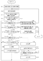
図3,図4は、図2に示す第1の実施形態の物品搬送システム、方法におけるロボット30、ロボット1が実行する動作処理のフローチャートであり、予め教示され記憶されているものである。この実施形態の場合、カゴ(収容手段)71にはワークWは、整列されずに山積みされているものとし、視覚センサ10でワークWを検出するとき、カゴ(収容手段)71を上下左右に4領域に分割して、各領域を順に撮像しワークWの位置、姿勢を検出するものとしている。
【0025】
この場合、ロボット30を駆動して、カゴ71を4つの領域の各中心位置が視覚センサ10の光軸と一致する位置に移動させるようにしている。又、検出したワークWをロボット1がハンド20で把持して取り出すときには、ロボット30がカゴ71を上昇させてワークWを把持することを容易にしている。むろん、ワークWを収容する収容手段(カゴ71やパレット70等)が小さく、収容手段の全領域が視覚センサ10の視野内に収まり、精度よく検出できる場合には、一度に撮像してもよく、又、ロボット1の動作稼働範囲の制限を受けないような場合には、収容手段を移動させるのではなく、ロボット1が移動し、視覚センサ10の位置を変えて撮像するようにしてもよい。又、ワークWを取り出すときも、収容手段(カゴ71)は上昇せず所定位置に保持したままとして、ワークWをロボット1がハンド20で把持して取り出すようにしてもよい。
【0026】
動作指令が入力されると、ロボット30の制御装置31のプロセッサは図3にフローチャートで示す処理を開始する。又、ロボット1の制御装置2のプロセッサは図4にフローチャートで示す処理を開始する。
ロボット30の制御装置31のプロセッサはまず、設定されている収容手段の取り出し位置にロボットを移動させ(ステップA1)、ロボットハンド50で該収容手段を把持し(ステップA2)、ロボット1へのワーク供給位置へ移動させ位置決めし、又、後述する指標n,mを「0」にセットする(ステップA3)。図2に示す例では、収容手段がカゴ71の例である。
【0027】
次にI/O信号線32を介して供給位置への移動完了信号をロボット1の制御装置2に送信する(ステップA4)。又、撮像可信号をも送信する(ステップA5)。
ロボット1の制御装置2は、移動完了信号が送られてきたかを監視しており(ステップB1)、移動完了信号が送られてくると、撮像位置にロボット1を移動させる(ステップB2)。そして、収容手段にワークWがなくなったとき、出力される収容手段空信号が送られて来たか、撮像可信号が送られて来たか監視する(ステップB3,B4)。最初は、カゴ71にはワークWが搭載されているから収容手段空信号は送られて来ず、ステップA5で出力された撮像可信号を受信するので、ステップB4からステップB5に移行し、視覚センサ10で撮像し、ワークWの位置、姿勢を求める。
【0028】
次にワークWの位置、姿勢を検出できたか否か判断し(ステップB6)、最初は検出できるので、ワーク検出信号として「あり」の信号を、I/O信号線32を介してロボット30の制御装置31に送信する(ステップB7)。
ロボット30の制御装置31は、このワーク検出信号の「あり」の信号を受信すると(ステップA6)、指標mを「0」にセットし(ステップA7)、ロボット30保持している収容手段(カゴ71)を設定所定量だけ上昇させる(ステップA8)。この上昇が完了した後、上昇完了信号をロボット1の制御装置2に送信する(ステップA9)。
【0029】
ロボット1の制御装置2は、上昇完了信号を受信すると(ステップB8)、ステップB5で求めたワークWの位置、姿勢に基いて、ロボットハンドの位置姿勢を補正して該検出したワークWを把持し取り出す(ステップB9)。そして、取り出し完了信号をロボット30の制御装置31に送信し(ステップB10)、次の工程の制御手段(加工機80の制御装置)からワーク取り付け指令が入力されるまで待機する(ステップB11)。そして、次の工程の制御手段(加工機80の制御装置)からワーク取り付け指令が入力されると、ロボット1を駆動して次の工程のワーク引き渡し位置に移動し、ワークを次の工程(加工機80)に引き渡し(ステップB12)、ステップB4に戻る。
【0030】
また、上記ステップB10で、ロボット1の制御装置2がワークWの取り出し完了信号を、次の工程の制御手段へ送信するようにしてもよい。
又、例えば、ロボット1がワークWを把持した時点または、ロボット1がワークWを把持した位置から、収容手段(カゴ71)上の所定の位置を通過した時点で、次の工程の制御手段へ、取り出し完了信号を出力するようにしてもよい。次の工程の制御手段は、ロボット1のワーク取り出し完了信号を受信してから、ワーク取り付け指令をロボット1の制御装置2に出力するようにすることで、シーケンスの制御をより確実に行うことができる。
【0031】
一方、ロボット30の制御装置31は、取り出し完了信号を受信すると(ステップA10)、ステップA8で上昇させた所定量だけ収容手段(カゴ71)を下降させ(ステップA11)、指標nを「1」インクリメントし(ステップA12)、該指標nが「4」であれば(ステップA13)、指標nを「0」にセットし(ステップA14)、「4」でなければそのままステップA15に進む。そして、この指標nで示される領域の設定されている中心位置に収容手段(カゴ71)を移動させる。この場合、収容手段(カゴ71)の高さは変化なく、水平移動して、次の領域を視覚センサ10の視野内に収めるようにして、ステップA6に戻る。
【0032】
以下、ロボット30の制御装置31は、ステップA6〜A15の処理を繰り返し実行し、n=0,1,2,3の各領域に巡回して収容手段(カゴ71)を平行移動させて位置決めする。一方、ロボット1の制御装置2は、n=0,1,2,3の各領域を順次撮像し、ワークWの位置、姿勢を求め、各領域からワークWを巡回して取り出し、次の工程に供給することになる。
【0033】
こうして、各領域から、ワークWが取り出されるが、視覚センサ10で撮像してもワークWの位置姿勢が検出されなかった場合、ロボット1の制御装置2は、ワーク検出信号として「無し」の信号をロボット30の制御装置31に送信し(ステップB13)、ステップB3に移行する。
【0034】
一方、ロボット30の制御装置31は、ステップA5で検出信号が「無し」の信号を受信すると、ステップA5からステップA16に移行し、指標mを「1」インクリメントし、該指標mが「4」に達しているか判断し(ステップA17)、達してなければ、ステップA12に移行し、ステップA12以下の処理を行う。以下、ロボット30の制御装置31は、撮像可信号を出力し、ワーク検出信号の「無し」の信号を指標mが「4」に達するまで、ステップA5,A6,A16,A17,A12〜A15の処理を繰り返し実行することになる。又、ロボット1の制御装置2はステップB3〜B6、B13の処理を繰り返し実行することになる。
【0035】
指標mが「4」になるまでの繰り返し実行中に、ワークWが検出され、ワーク検出信号が「あり」の信号がロボット1の制御装置2から出されると(ステップB7)、ロボット30の制御装置31はステップA7以下の処理を行い、ロボット1の制御装置2は、ステップB8以降の処理を実行する。
【0036】
そして、指標mが「4」に達したとき、すなわち、n=0,1,2,3の領域を撮像してワークWを検出できなかったときには、収容手段(カゴ71)内に検出できるワークWがないことを意味するから、ステップA17からステップA18に移行し、収容手段にワークWが無いことを示す「収容手段空信号」をロボット1の制御装置2に送信し、収容手段(カゴ71)を設定されている空の収容手段の載置位置(空カゴ載置位置)に載置させ(ステップA19)、ステップ1に戻る。
【0037】
一方、ロボット1の制御装置2は、「収容手段空信号」を受信すると(ステップB3)、設定されている退避位置にロボット1を移動させ(ステップB14)、ステップB1に戻る。
そして、ワークWが収容されている新しい収容手段(カゴ71)が取り出され、前述した動作処理によって、ワークWは順次次の工程の加工機80に供給されることになる。
【0038】
停止指令が入力された場合には、ロボット30,1の制御装置31,2は、停止処理に移行し、ロボット1の制御装置2は、ロボットハンド20がワークWを把持していれば、収容手段(カゴ71)内に戻し、退避位置へロボット1を移動させる。又、ロボット30の制御装置31は、収容手段(カゴ71)を空収容手段の載置位置(空カゴ載置位置)に載置し、待機位置に移動させ動作を終了する。この終了処理については、詳細な説明は省略する。
【0039】
上述した実施形態では、収容手段(カゴ71)を4つの領域に分け、各領域が視覚センサ10の視野内に入るように収容手段(カゴ71)を水平移動させたが、収容手段の形状によっては、該収容手段を平行移動させて位置を変えるよりも、収容手段を垂直軸回りに回転させてその姿勢を変えることによって、収容手段の全領域が視覚センサ10の視野内に入るようにしてもよい。すなわち図3のステップA15の処理が「領域nの位置への移動」ではなく、「領域nの位置への回転」となる。
【0040】
又、上述した実施形態では、収容手段(カゴ71)を4つの領域に分け、各領域が視覚センサ10の視野内に入るように収容手段(カゴ71)を水平移動(直線移動又は回転移動)させ、かつ、ハンド20でワークWを把持し取り出す際には、収容手段(カゴ71)を所定量上昇させたが、収容手段(カゴ71)の全領域が視覚センサ10の視野内に入る場合で、かつ、ロボット1の稼働範囲に余裕があり、収容手段(カゴ71)を上昇させなくても、ハンド20でワークWを把持できるような場合には、ロボット30は、収容手段(カゴ71)を所定位置に位置決めして、該位置に保持するだけでよい。
【0041】
この場合、図3に示す処理で、ステップA7〜A15,A16〜A18の処理は必要がない。すなわち、ステップA6で、検出信号が「あり」の場合は、ステップA5に戻り、検出信号が「無し」の場合は、ステップA19に移行するようにすればよい。なお、ステップA3での指標n,mを「0」にセットする処理も必要がなくなる。
【0042】
又、図4のロボット1の動作処理では、ステップB3,B8,B10の処理も必要で無くなる。そして、撮像してワークWを検出できないときにはステップB13からステップB14に移行することになる。又、ステップB2かステップB4へ、ステップB7からステップB9へ、ステップB9からステップB12へ移行することになる。
【0043】
なお、この場合、ロボット30は、収容手段(カゴ71)を、長時間、所定位置に保持し続けることになるので、一旦所定位置に収容手段(カゴ71)を位置決めした後は、ロボット30の各軸にブレーキをかけ、各軸のサーボモータをサーボオフとして、その駆動を停止し、収容手段(カゴ71)を空き収容手段位置に返却するときに、サーボオンとして、各軸サーボモータを駆動し、ブレーキを解除するようにすればよい。すなわち、ステップA3とステップA4の間に、ブレーキオン、サーボオフの処理を入れ、ステップA19の前にサーボオン、ブレーキ解除の処理を入れればよい。
【0044】
又、視覚センサ10で収容手段(カゴ71)の全領域を視野内に収めることができない場合でも、ロボット1の稼働範囲であれば、収容手段(カゴ71)の領域を分割し、各分割領域を視野内に入れるようにロボット1が移動するようにしてもよいものである。
【0045】
又、上述した実施形態では、収容手段(カゴ71)に搬送対象物品としてのワークWが整列されずに山積みされた状態で、ロボット1による取り出し位置に供給された例であった。しかし、収容手段(カゴ71等)にワークWが整列されて配置されているような場合には、ワークWの位置姿勢を検出する必要がなく、ロボット30は収容手段(カゴ71等)を所定位置に位置決めし保持しておけばよい。そしてロボット1は、整列された位置、姿勢情報に基いて、従来と同様に、ワークWを把持して取り出せばよいことになる。なお、この場合でも、ロボット1の稼働範囲の外に、収容手段(カゴ71等)に整列配置されたワークWがあるような場合には、ロボット30を駆動してこの収容手段(カゴ71等)を水平移動させて、ロボット1の稼働範囲内に収まるようにすればよく、システムのフレキシビリティーが向上する。
【0046】
さらに、このような部品搬送システムでは、取り出した部品の個数または、収容手段に残っている部品の数を外部の生産管理コンピュータや、シーケンサに出力すると生産ラインの状態をモニタするために役立つ。また、部品の残り数量が一定以下になった場合に、外部に信号を出力し、部品補充または、収容手段の交換のタイミングが近いことを外部に伝えるようにしてもよい。このようにすると、部品の補充、収容手段の交換を空き時間なく行い、生産効率を上げることができる。
【0047】
この場合、図3に示す処理を以下のように多少変更することで可能となる。まず、作業者が、収容手段(カゴ71)を棚60内に置くときに、収容手段に収容された部品の個数をロボット30の制御装置31のレジスタなどに設定する。ロボット30の制御装置31では、ステップA3で収容手段を取り出し、ワーク供給位置へ移動して位置決めした際に、部品の取り出し個数をカウントする、カウンタを「0」にセットする。ロボット30の制御装置31は、取り出し完了信号を受信(ステップA10)するごとに、ステップA11において、この取り出し個数カウンタを1だけインクリメントし、変更後の新しいカウンタの値を、外部の生産管理用コンピュータや、シーケンサに図2には図示しないI/O信号線などを介して出力するようにしてもよい。また、取り出し個数の代わりに、レジスタに設定された、部品の個数からカウンタの値を減算し、収容手段内に残っているワークの個数を計算してこの値を出力するようにしてもよい。
【0048】
さらに、取り出し個数のカウンタまたは、前記減算により求めた収容手段内に残っているワークの個数が一定の条件を満たしたとき、例えば、一定個数以上取り出したときや、残りのワークの個数が一定数以下になったときなどに、外部の生産管理用コンピュータや、シーケンサにワーク補充または収容手段の交換時期が近いことを知らせるためにI/O信号を出力するようにしてもよい。これらの処理は、ステップA11で行うようにしてもよい。
さらに、本発明の別の実施形態として、棚60に格納されたパレット70または、カゴ71の位置や姿勢にばらつきがある場合に、センサによりパレット70、またはカゴ71の位置または姿勢を検出して、棚60から取出しを行うようにする。
【0049】
この場合、ロボット1に装着されているセンサ10およびセンサ制御装置3と同様のセンサをロボット30に装着し、パレット70、またはカゴ71を棚60から把持、取出しを行う際に、すなわち、図3におけるステップA2の処理動作の際に、当該センサにより、パレット70、またはカゴ71の把持部分の位置や姿勢を検出し、ロボット30の把持位置を修正する。
【0050】
センサによる把持位置の検出方法としては、例えば、前述したワークWの位置、姿勢を検出する方法と同様に、ロボット30のハンド50で把持する部分のパレットの形状をテンプレート画像として教示し、センサの画像からテンプレートと同形状の把持部分を検出して、パレットの把持部分の位置を正確に求めるなどの方法を適用する。この他にも、パレットの複数のコーナ部の位置を検出し、それによってパレット全体の位置や姿勢を正確に計測するようにしてもよい。これらの方法は、すでに周知事項であるから詳細な説明は省略する。
【0051】
図5は、本発明の第2の実施形態の要部ブロック図である。上述した第1の実施形態の各態様は、収容手段に格納されている加工対象のワーク等の物品を取り出して、次の工程に引き渡す搬送システムであった。しかし、この図5に示す第2の実施形態は、逆に加工機等で加工されたワーク等の物品を整列して収容手段に格納する物品搬送システム及び方法に関するものである。
【0052】
図5において、ロボット1の制御装置2は加工機80でワークの加工が完了した時点で、I/O信号線33を介して「加工完了」のI/O信号を受信すると、ロボット1は、加工済みのワークWを加工機80から取り出し、ロボット30が把持しているカゴ71内でワークの存在しない場所、または最上段のワークの高さなどの情報を視覚センサ10で検出し、その情報に従ってワークWをカゴ71に詰める。ロボット1は、カゴ71がワークWで満杯になると、交換指令を出力し、ロボット30は、該「交換指令」の信号を受信すると、カゴ71を図示しない棚60の所定位置へ搬送する。
このようにして、ロボット1とロボット30により、加工機80で加工されたワークWをカゴ71に整列して収納し搬送するものである。
【0053】
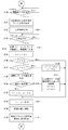
図6,図7は、この図5に示す加工機80で加工されたワークWを収容手段(カゴ71)に、整列して収容し、該収容手段(カゴ71)を棚60まで搬送する搬送システム、搬送方法のロボット30,1の制御装置31,2のプロセッサが実項する動作処理のフローチャートである。
【0054】
収容手段を指定して、動作指令が入力されると、ロボット30の制御装置31のプロセッサは図6にフローチャートで示す処理を開始する。又、ロボット1の制御装置2のプロセッサは図7にフローチャートで示す処理を開始する。
ロボット30の制御装置31のプロセッサはまず、指定されている収容手段の取り出し位置にロボット30を移動させ(ステップC1)、ロボットハンド50で該収容手段を把持し(ステップC2)、ロボット1へのワーク受け取り位置へ移動させ位置決めする(ステップC3)。図5に示す例では、収容手段がカゴ71の例である。
【0055】
次にI/O信号線32を介して受け取り位置への移動完了信号をロボット1の制御装置2に送信する(ステップC4)。そしてロボット1の制御装置2からI/O信号線32を介して収容手段の交換指令が入力されているか(ステップC5)、停止指令が入力されているか(ステップC6)、リターン指令が入力されているか(ステップC7)、上昇指令が入力されているか(ステップC8)、シフト指令が入力されているか(ステップC9)、順次判断する。
【0056】
一方、ロボット1の制御装置2は、移動完了信号が送られてきたかを監視しており(ステップD1)、移動完了信号が送られてくると、収容手段に最初にワークWを載置する設定されている位置を撮像する位置に、ロボット1を移動させ、視覚センサ10で撮像し、ワークの最上面の高さを求め記憶する。又、この初期位置X軸方向の位置Xsをレジスタxに記憶し、Y軸方向の移動回数を記憶するレジスタyを「0」にセットする(ステップD2)。この実施形態では、ロボット1がX軸方向に移動して、ワークWをカゴ71に詰め込み、ロボット30が、X軸方向と直交するY軸方向に所定回数、所定設定ピッチで移動することにより、ワークWをカゴ71内に整列して、詰め込むようにしている。
【0057】
このステップD2による撮像で、ワークWが検出されたか判断し(ステップD3)、ワークが検出されなければ、このカゴ71にはワークWが載置されてない、空のカゴ71であることを意味することからステップD10に進む。又、ワークが検出されれば、ワークが途中まで詰め込まれていることを意味するので、次から詰め込む位置を求める処理を開始する。
【0058】
まず、設定されているピッチ量Δxだけロボット1をX軸方向に移動させ、レジスタxにこのピッチ量Δxを加算する(ステップD4)。このレジスタxに記憶する値が設定値Xe以上か判断し(ステップD5)、設定値Xe以上でなければ、ステップD8に移行して、この位置で撮像し、ワークの最上面の高さを求める。そして、ステップD2で求めた、ワークを詰め込む先頭位置でのワークの最上面の高さと一致するか判断し(ステップD9)、一致しなければ、ステップD4に戻る。以下、ステップD4からステップD9の処理を繰り返し実行するが、ステップD5でレジスタxの値が設定値Xe以上になると、すなわち、X軸方向へのワーク詰め込みの限界に達したならば、ロボット1を先頭位置Xsに戻し、ロボット30の制御装置31にI/O信号線32を介してシフト指令を出力すると共に、レジスタxに先頭位置Xsを格納し、レジスタyを1インクリメントする(ステップD6)。そして、ロボット制御装置31からシフト完了信号が送られて来たか判断する(ステップD7)。
【0059】
一方、ロボット30の制御装置31は、ロボット制御装置2からシフト指令が入力されたことをステップC9で検出し、設定されている所定量Δyだけ、Y軸方向にカゴ71を移動させ、シフト完了信号をロボット制御装置2に送信する(ステップC10,C11)。
【0060】
ロボット1の制御装置2は、シフト完了信号を受信するとステップD7からステップD8に移行し、前述した処理を実行する。
以上のようにして、撮像して得られるワーク最上面の高さが同じである限り、ロボット1はX軸方向に所定ピッチ量Δx移動することに撮像し、又、X軸の値が設定値Xe以上になるとロボット30がカゴ71をY軸方向にΔyだけ移動させることにより、先頭位置Xsから所定ピッチ量Δx移動し、ワーク最上面の高さが変わった位置(高さが低い)を検出する。最初は、ワークが詰められていないカゴ71又は途中までしか詰め込まれていないカゴ71が供給されるものであるから、いずれかの位置で、ワーク最上面の高さが異なる位置が検出され、該位置から、ワーク詰め込まれることになる。
【0061】
こうして、カゴ71が提供され、ワークが最初に詰め込まれる位置が検出した後は、ロボット1の制御装置2は、停止指令が入力されたか(ステップD10)、加工機から加工完了信号がI/O信号線33を介して入力されたかを判断し(ステップD11)、待機する。
【0062】
加工機80から加工完了信号が入力されると、ロボット1は加工機80から加工されたワークを取り出し(ステップD12)、上昇指令をロボット30の制御装置31に出力し(ステップD13)、ロボット30の制御装置31から上昇完了信号が入力されるまで待つ(ステップD14)。
ロボット30の制御装置31では、ステップC8で上昇指令を受信したことを判別すると、カゴ71を所定量Δzだけ上昇させ(ステップC12)、その後上昇完了信号をロボット制御装置2に送信する(ステップC13)。
【0063】
ロボット1の制御装置2は、この上昇完了信号を受信すると、レジスタxに記憶する位置に対応するX軸位置の位置(Y軸位置は一定値)に位置決めし、測定したワーク最上面位置に対してカゴ71を上昇した分補正して下降し、取り出したワークWを載置したあと撮像位置の高さまで上昇し、その後、載置完了信号を出力する(ステップD15)。
【0064】
ロボット30の制御装置31は、載置完了信号を受信すると(ステップC14)、ステップC12で上昇した分Δyだけ下降し(ステップC15)、ステップC5に戻り、前述した各指令が入力されたかを判断する(ステップC5〜C9)。
一方、ロボット1の制御装置2は、レジスタxに所定ピッチ量Δx加算し(ステップD16)、該レジスタxの値が設定値Xe以上か判断する(ステップD17)。設定値Xeを越えていなければ、該X軸方向のライン上に載置すべき空間があることを意味し、ステップD10に移行し、前述したステップD10以降の処理により、ワークをレジスタxで記憶するX軸の位置に載置する。
【0065】
又、設定値Xe以上の場合には、このライン上では、同一高さレベルでワークを詰め込む位置がないことを意味するので、ステップD18に移行し、レジスタyの値が、Y軸方向にワークを詰め込む数として設定されている値Yeを越えているか判断する(ステップD18)、越えていなければ、ロボット1を先頭位置Xsに戻し、シフト指令をロボット制御装置31に出力し、レジスタyを「1」インクリメントし、レジスタxに先頭位置Xsを格納し(ステップD19)、シフト完了信号を受信するのを待って(ステップD25)、ステップD10に移行する。ロボット30の制御装置31ではシフト指令を受信すると前述したようにステップC9〜C11の処理によって、Δyだけカゴ71をY軸方向にシフトさせ、シフト完了信号を出力する。
【0066】
ステップD18において、レジスタyの値が、設定値Yeを越えていると判断されたときには、現在の位置で撮像し、ワークの最上面の高さを求め(ステップD20)、該高さが設定値を超えているか判断する(ステップD21)。この高さが設定値を越えていれば、カゴ71には満杯になるまでワークWが収納されたことを意味し、収容手段(カゴ71)の交換指令ロボット制御装置31に出力する(ステップD23)。一方、高さが設定値を越えていなければ、ロボット1を先頭位置Xsに戻し、リターン指令を出力し、レジスタyを「0」とし、レジスタxに先頭位置Xsを格納し(ステップD22)、リターン完了信号を待って(ステップD24)、ステップD10に移行する。
【0067】
ロボット30の制御装置31では、交換指令が入力されると(ステップC5)、現在保持している収容手段(カゴ71)を元の取り出した位置に戻し、空の収容手段(カゴ71)が配置された位置に移動し(ステップC16)、ステップC2以下の処理を実行する。
【0068】
又、リターン指令を受信すると(ステップC7)、カゴ71を先頭位置に戻し、リターン完了信号をロボット1の制御装置2へ送信する(ステップC18)。すなわち、カゴ71をΔyだけ移動させたが、この移動させた分の総計分逆方向に移動させ、空の収容手段(カゴ71)が配置された位置と同じ位置に移動し、カゴの先頭位置からワークが格納されるようにするものである。
なお、停止指令が入力されたときには(ステップC6)、ロボット30の制御装置31は、収容手段(カゴ71)を取り出した位置に戻し、待機位置に移動して停止する(ステップC17)。
【0069】
上述した第2の実施形態では、ロボット1に視覚センサを設けて、該視覚センサ10によって、ワークの検出、その最上面位置の高さ等を求めたが、これは、供給される収容手段(カゴ71やパレット70)に、すでにワークWが途中まで格納されている場合も対応できるようにしたからであり、空の収容手段(カゴ71やパレット70)が常に供給されるとすれば、ワークを載置する順番パターンを決めておけば、視覚センサ10なしに、収容手段(カゴ71やパレット70)にワークを詰め込むことができる。この場合、図7に示すフローチャートにおいて、ステップD3〜D9の処理は必要がなくステップD2からステップD10に移行する。又、ステップD21は、ステップD18がYesとなる毎にカウンタをカウントアップし、該カウンタが満杯を示す数に達したか否かの判断に変え、満杯を示す数を越えたときには、ステップD23へ、そうではないときにはステップD22に移行するようにすればよい。
【0070】
又、ロボット1の稼働動作範囲に余裕があるときには、ロボット30により収容手段(カゴ71)をΔyシフトさせる代わりに、ロボット1がこのシフト分移動するようにしてもよい。この場合は、図6において、ステップC9〜C11の処理は無くなり、図7において、ステップD19の処理は、シフト指令の出力の代わりに、該ロボット1をシフト分移動させることになる。さらに、収容手段を上昇させずに一定の位置に保持するようにしてもよい。この場合、ロボット30は、収容手段(カゴ71)を、長時間、所定位置に保持し続けることになるので、一旦所定位置に収容手段(カゴ71)を位置決めした後は、ロボット30の各軸にブレーキをかけ、各軸のサーボモータをサーボオフとして、その駆動を停止し、収容手段(カゴ71)を格納するときにサーボオンとして、各軸サーボモータを駆動し、ブレーキを解除するようにすればよい。
又、収容する物品の形状によっては、該物品を収容手段に収容する際に、ロボット30によって収容手段を垂直中心軸回りに回動させて、物品の収容を容易にするようにしてもよい。
【0071】
さらに、第1の実施形態と同様に、ロボット30にも視覚センサを装着し、パレット70または、カゴ71を棚60に格納する際、取り出す際に、当該センサにより、パレット70または、カゴ71を格納する棚の位置、姿勢、又はパレット70または、カゴ71の位置姿勢を検出し、ロボット30の格納動位置、取り出し位置を修正するようにしてもよい。
【0072】
また、第1の実施形態と同様に、外部コンピュータや、シーケンサに収容した部品の個数や、残り部品の個数が一定数以上になったことを示す信号を出力し、生産状況のモニタや、収容手段交換のタイミングを通知に利用するようにしてもよい。この場合、収容手段に収容したワークの個数もしくは、残りワークの個数(収容手段に収容可能なワークの個数と、すでに収容したワーク個数の差)を外部に出力したり、またはこれらの数が一定の個数以上または、以下になった場合に信号を出力するようにしてもよい。
【0073】
第1の実施形態同様に、ワーク収容手段を棚60に置いた際に、ロボット30の制御装置31のレジスタに収容手段に収容可能なワークの個数を設定し、制御装置31がステップC14で載置完了信号を、ロボット1から受け取るごとに、制御装置31内の収容部品数を記録するカウンタを「1」ずつインクリメントし、このカウンタの値や、レジスタに設定されている収容可能なワーク個数との差の値を、外部コンピュータや、シーケンサに出力してもよい。
【0074】
さらに、収納部品数のカウンタまたは、前記減算により求めた収容手段内に収容可能なワークの個数が一定の条件を満たしたとき、例えば、収納部品数が一定個数以上となったときや、収容可能なワーク個数が一定数以下になったときなどに、外部の生産管理用コンピュータや、シーケンサに収容手段の交換時期が近いことを知らせるためにI/O信号を出力するようにしてもよい。これらの処理は、ステップC15で行うようにしてもよい。
【0075】
又、ロボット1が部品を取り出す動作中に、何らかのエラーが発生し、ロボット1が動作を継続できない場合、本システムでは、ロボット30の動作により、ロボット1のエラー解除を補助し、システムを停止することなく連続運転を可能にすることもできる。
【0076】
図4において、ロボット1の制御装置2は、ステップB5で求めたワークWの位置、姿勢に基いて、ステップB9でロボットハンドの位置姿勢を補正してワークWを把持し取り出す。このとき、補正されたハンドの位置姿勢がロボット1の動作範囲を超えるため、取り出し動作が不可能となる場合があり得る。ワークがカゴの中に山積みされていて、ワークの位置、姿勢変化が大きい場合、ワークの位置姿勢をセンサで計測できても、取り出し時に必要な位置、姿勢をロボットが取れない状況が、特にカゴの壁面付近や、視覚センサ10の視野の周辺部等の、離れた位置にあるワークで発生しやすい。
【0077】
この場合、以下のようにロボット30により、ワークWの位置、姿勢を視野中央部に近づくと期待される方向に収容手段(カゴ71)を移動し、再度ロボット1が計測、取り出しを行う。これにより、検出するワークがロボット1で到達可能な動作範囲内にくるようにしてワークの取り出しを続行することができる。
【0078】
まず、検出したワークWを把持する位置、姿勢がロボット1の動作範囲を超えている場合、ロボット1の制御装置2は、動作不可能な位置姿勢への移動として、アラーム状態となりロボット1のプログラムがアラームとなった場合に、アラーム処理用のプログラムを起動することは通常のロボット制御装置で可能である。制御装置2は、アラーム処理用のプログラムを起動し、ステップB10で、ワーク取り出し完了信号の代わりに、「ワーク取り出しが不能」であることを示す信号をロボット30の制御装置31へ出力する。
【0079】
ロボット1は、ステップB11,B12をスキップし、撮像位置に移動したのち、ステップB4に戻り、アラーム処理プログラムを終了し、撮像可指令を待つ。ロボット1は、撮像指令を受信すると、再びセンサによるワークの計測を行い、計測したワークの取り出しを続行する。
一方、ロボット30は、図3のフローチャートにおいて、ステップA9〜A11の間を、図8に示す処理に置き換え、取り出し不能時のエラー解除動作を行う。
【0080】
ワークの収容された収容手段(カゴ71)を把持したロボット30は、ステップA9の処理の後、取り出し不能信号を受信したか、取り出し完了を受信したか判断しており(ステップA10−1,A10)ロボット1から「ワーク取り出し不能」の信号を受け取ると(ステップA10−1)、エラー復旧用のプログラム処理に移行する(ステップA10−3以降)。このエラー復旧用プログラムでは、エラーリカバーの回数をカウントする内部カウンタRの値を1だけインクリメントする(ステップA10−3)。カウンタRが4でなければ(ステップA10−4)、図3のステップA8で上昇させた所定量だけ収容手段(カゴ71)を下降させる(ステップA10−5)。次に、収容手段を所定量移動させる(ステップA10−6)。このときの移動は、ロボット1が取り出し可能な位置、姿勢にワークを位置させることが目的であるので、例えば収容手段の周辺部が視野中心に近づくように、水平移動させたり、ワーク上面とがカメラ光軸とのなす角度が小さくなるように、ワークを収容手段中央部に向けて荷崩れが起きない程度の角度だけ傾けるような移動を行う。移動の量と、移動方向はカウンタRの値に応じて予め定めた所定の移動パターンから選択して行ってもよい。または、ステップB5で、ロボット1が検出したワークWの位置、姿勢情報を利用し、当該検出ワークWが視野中心に近づき、傾きが小さくなるような方向に移動するようにしてもよい。
【0081】
このようにして、収容手段の位置を変更(ステップA10−6)した後、ステップA5へ戻り、ロボット1の制御装置2に対し、撮像可指令を出力し(ステップA5)、ロボット1の制御装置2は、上記撮像可指令を受けて、撮像と、ワーク位置検出を繰り返す。カウンタRが4になる前に、取り出しが完了すると、カウンタRは「0」にリセットされる(ステップA10−2)。
【0082】
万一、カウンタRが4になるまで、移動、再計測を繰り返しても取り出しができない場合は、ロボット30をアラーム停止し、作業者によるエラーの解除、復旧を待つ(ステップA10−7)。
以上が、取り出し不能時のエラー解除動作処理である。又、第2の実施形態における加工済みワークを収容手段に収容する際に何らかの異常が生じた場合にも上述したエラー解除処理と同等な処理が適用できるものである。すなわち、図6のステップC13〜ステップC15の間に図8に示す処理と同等な処理を適用すればよい。図8においてステップA9,ステップA11,ステップ5がステップC13,ステップC15,ステップ4に代わるものである。
【0083】
前述の第1および第2の実施例では、カゴ71から取り出したワークWを加工機80へ供給する、あるいは、加工機80で加工済みとなったワークWを、カゴ71に収容する例を示した。ここでカゴ71から取り出したワークを、図示しない仮置き台に置く、または加工機から取り出したワークを一旦仮置き台に置き、該仮置き台上のワークを、カゴ71に収容するようにしてもよい。すなわち、物品取り出しの次工程を仮置き台へのワーク搬送としたり、あるいは、収容手段へワークを格納するための前工程が、仮置き台からのワークの取り出しとなるようにしてもよい。
【0084】
これは、特に、ロボット1が、未加工ワークの加工機への供給と、加工済みワークの加工機からの取り出しを交互に行い、ロボット30が、未加工ワーク用を収納するカゴと、加工済みワークを収納するカゴを交互に取り出して、ロボット1の動作範囲内の供給位置へ位置決めする場合に、加工機を待ち時間なく運転できる効果がある。
仮置き台を利用しないときには、次のようなシーケンスとなる。
【0085】
ロボット1は、加工機80での加工が終了すると、加工済みワークを加工機から取り出す。ロボット1は、ロボット30が把持した加工済みワーク収納用のカゴ内に、取り出した加工済みワークを収納する。ロボット30は、加工済みワークを収納したカゴを棚60の所定の場所に戻す。次にロボット30は、未加工ワークの入ったカゴを棚60より取り出し、ロボット1の動作範囲内に位置決めする。ロボット1は、該未加工ワークの入ったカゴからワークを取り出し、加工機へセットすると、次のワークに対し、加工が開始される。
【0086】
この場合、加工済みワークを取り出し、未加工ワークをセットするまでの間に、ロボット30は、加工済みワーク用カゴと、未加工ワーク用カゴの入れ替えが必要であり、この間加工機を運転することができない。
本ワーク搬送システムの次工程、前工程の一方または両方を仮置き台へ/からの搬送とすることにより、ロボット1は、ロボット30が未加工ワーク、加工済みワーク用のカゴを入れ替えの間を待つことなしに、加工機と仮置き台の間でワークの搬送を行うことが可能となり、加工終了から、次ワークの加工開始までの時間を短縮し、生産効率を上げることが可能となる。
【0087】
図9は仮置き台を利用して未加工ワークの加工機への供給と、加工済みワークの加工機からの取り出しを交互に行う本発明の第3の実施形態の動作シーケンスの流れ図である。
【0088】
システム構成は、図1、図2に示した構成に仮置き台が、ロボット30、ロボット1の動作範囲内に設けられている点のみが相違するものである。なお、仮置き台の図示は省略している。
まず、ロボット30は、棚60に載置されている未加工のワークを収容する収容手段(カゴ71)を棚60から取り出し、ワーク取り出し位置に位置決めする(工程100)。ロボット30とロボット1は協同し(工程101,200)、ロボット1がこの収容手段(カゴ71)に収容されている未加工のワークを取り出し、仮置き台に置く(工程201)。
【0089】
一方、ロボット30は、未加工のワークを収容した収容手段(カゴ71)を棚60の元の位置に戻す(工程102)。さらに、加工済みワークが収容されている収容手段を棚60から取り出しワーク収容位置に位置決めする(工程103)。
ロボット1は、加工機80,81から加工終了信号を受信すると、その加工機80,81から加工されたワークを取り出し仮置き台に置く(工程202)。さらに、仮置き台に載置されている未加工のワークを、加工済みワークを取り出した加工機80,81に取り付ける(工程203)。
【0090】
そして、ロボット30とロボット1は、仮置き台に載置された加工済みワークを収容手段(カゴ71)に収容する収容処理を行い、加工済みワークを加工済みワーク収容手段に格納する(工程104,204)。その後、ロボット30は加工済みワークを収容する収容手段を元の棚60の位置に戻す(工程105)。そしてロボット30は工程100に、又ロボット1は工程200に移行する。
【0091】
以上が仮置き台を利用して加工機と未加工、加工済みのワークの交換搬送システムの概要である。
図10〜図13は、上述した未加工、加工済みのワークの交換搬送システムにおける各ロボットの動作処理のフローチャートであり、図10,図11は、収容手段を取り扱うロボット30の動作処理フローチャートである。又、図12,図13はワークを取り扱うロボット1の動作処理フローチャートである。
【0092】
ロボット30の制御装置31は、未加工ワーク収容手段取り出し指令があるか判断し、この指令があるまで待機している(ステップE1)。未加工ワーク収容手段取り出し指令は後述するように、ロボット1の制御装置2からI/O信号線を介して送られてくる。又は、ワーク自動交換搬送指令が入力されたときにも、この未加工ワーク収容手段取り出し指令が自動的に発生する。この未加工ワーク収容手段取り出し指令を受けると、ロボット30の制御装置31は、設定されている未加工ワーク収容手段の取り出し位置にロボット1を移動させ、ロボットハンド50で該収容手段を把持し、ロボット1へのワーク供給位置に収容手段の指標nで示される領域を位置決めし、I/O信号線32を介して供給位置への移動完了信号をロボット1の制御装置2に送信する(ステップE2〜E5)
ロボット1の制御装置2は、移動完了信号が送られてきたかを監視しており(ステップF1)、移動完了信号が送られてくると、撮像位置にロボット1を移動させ(ステップF2)、視覚センサ10で撮像し、ワークWの位置、姿勢を求めめ(ステップF3)、ワーク検出信号をI/O信号線32を介してロボット30の制御装置31に送信する(ステップF4)。そして、収容手段(カゴ71)の上昇完了信号を待つ(ステップF5)。なお、最初は収容手段には未加工のワークが予め収容され、最初は必ずワークWは検出されるものである。又、以後は後述するように、必ずワークWは検出されるように制御されている。
【0093】
ロボット30の制御装置31は、このワーク検出信号を受信すると(ステップE6)、ロボット30が保持している収容手段(カゴ71)を設定所定量だけ上昇させる(ステップE7)。この上昇が完了した後、上昇完了信号をロボット1の制御装置2に送信する(ステップE8)。
【0094】
ロボット1の制御装置2は、上昇完了信号を受信すると(ステップF5)、ステップF3で求めたワークWの位置、姿勢に基いて、ロボットハンドの位置姿勢を補正して、該検出したワークWを把持し取り出し、仮置き台に置く(ステップF6)。そして、取り出し完了信号をロボット30の制御装置31に送信するし(ステップF7)。
【0095】
一方、ロボット30の制御装置31は、取り出し完了信号を受信すると(ステップE9)、ステップE7で上昇させた所定量だけ収容手段(カゴ71)を下降させ(ステップE10)、指標nを「1」インクリメントし(ステップE11)、該指標nが「4」であれば(ステップE12)、指標nを「0」にセットし(ステップE13)、「4」でなければそのままステップE14に進む。そして、この指標nで示される領域の設定されている中心位置に収容手段(カゴ71)を水平移動させその領域を視覚センサ10の視野内に収める位置に位置決めし、撮像指令をロボット1の制御装置に送信する(ステップE14)。
【0096】
一方、ロボット1の制御装置2は、出力される撮像指令が送られて来たか、退避指令が送られてきたか監視しており(ステップF8,F9)。撮像指令を受信すると、視覚センサ10で撮像し、ワークWが検出できたか否か判断し(ステップF10,F11)、検出できれば、ワーク検出ありの信号を(ステップF13)、検出できなければワーク検出無しの信号を(ステップF12)をロボット30の制御装置31に送信する。
【0097】
一方、ロボット30の制御装置31は、ステップE15でワーク検出「無し」の信号を受信すると、すなわち次の領域でワークが検出されない場合には、ステップE15からステップE16に移行し、指標mを「1」インクリメントし、該指標mが「4」に達しているか判断し(ステップE17)、達してなければ、ステップE11に移行し、ステップE11以下の処理を行う。以下、ロボット30の制御装置31は、撮像信号を出力し、ワーク検出「無し」の信号を指標mが「4」に達するまで、ステップE14,E15,E16,E17,E11〜E13の処理を繰り返し実行することになる。
【0098】
指標nで示される領域でワークWが検出され、ステップE15でワーク検出「無し」の信号を受信すると、指標mを「0」にセットし(ステップE18)、収容手段を元の位置に戻し(ステップE21)、待機位置に復帰する(ステップE22)。その結果、指標nはワークを検出できる領域を記憶していることになり。次の未加工ワーク取り出し時には、この指標nで示される領域にステップE4で位置決めされることになる。
【0099】
一方、指標mが「4」に達し、4つの領域を撮像してワークWを検出しても、ワークWを検出できない場合には、当該収容手段には未加工のワークWが存在しないことを意味するので、ロボット1の制御装置2へロボット1の退避指令を出力すると共に(ステップE19)、未加工ワークの収容手段の取り出し位置を次の位置に設定し、指標n、mを「0」にセットし(ステップE20)、ステップ21に移行する。次からは、未加工ワークが収容された新たな収容手段が取り出され、該収容容器のの最初の領域より未加工のワークが取り出されることになる。
【0100】
ロボット1の制御装置2は、ワーク検出ありの信号を出力した後(ステップF13)、ロボット1を待機位置に戻し(ステップF14)、加工機80,81から加工完了信号が入力するまで待つ(ステップF15)。
加工機80,81から加工完了信号が出力されると、加工済みのワークWを加工機から取り出し仮置き台に置き(ステップF16)、仮置き台に載置されている未加工のワークWを、ワークを加工済みのワークを取り出した加工機80,81に取り付ける(ステップF17)。その後、加工済みワーク収容手段取り出し指令をロボット30の制御装置31に送信し(ステップF18)、がロボット1は待機位置に移動する(ステップF19)。
【0101】
ロボット30の制御装置31は、加工済みワーク収容手段取り出し指令を受信すると(ステップE23)、指定されている加工済みワーク収容手段の取り出し位置にロボット30を移動させ(ステップE24)、ロボットハンド50で加工済みワーク収容手段を把持し(ステップE25)、受け取り位置(x,y)に位置決めする(ステップE26)。なお最初は、初期設定で、受け取り位置(x,y)としてスタート位置(xs,ys)に位置決めされる。
【0102】
次に受け取り位置への移動完了信号をロボット1の制御装置2に送信する(ステップE27)。そしてロボット1の制御装置2から上昇指令があるまで待機する(ステップE28)。
ロボット1の制御装置2は、この移動完了信号を受信すると(ステップF20)、仮置き台から加工済みワークを取り出すと共に、上昇指令をロボット30の制御装置31に出力する(ステップF21,F22)。
ロボット30の制御装置31に上昇指令を受けると(ステップE28)、収容手段を所定量ΔZ上昇させた後、上昇完了信号を出力する(ステップE29,E30)。
【0103】
ロボット1の制御装置2は、この上昇完了信号を受信して(ステップF23)、収容容器の(x,y)の位置に加工済みワークを載置し、載置完了信号を出力する(ステップF24)。そして、次の載置位置がワーク載置可能かの判断処理を開始する。
【0104】
ロボット30の制御装置32は、載置完了信号を受信すると(ステップE31)、ステップE29で上昇させた分ΔZだけ下降させ(ステップE32)、この加工済みワークを収容する収容手段を元の位置に戻し(ステップE33)、その後待機位置に移動させる。そして、加工済みワーク載置位置(x,y)が送られてくるのを待つ(ステップE34)。
【0105】
ロボット1の制御装置2は、載置完了信号を出力(ステップF24)した後、次の載置位置にワーク載置可能かの判断処理を開始する。ロボット1の制御装置2は、レジスタxに所定ピッチ量Δx加算し(ステップF25)、該レジスタxの値が設定値Xeを越えたか判断する(ステップF26)。設定値Xeを越えていなければ、該X軸方向のライン上に載置すべき空間があることを意味し、ステップF33に移行する。又、設定値Xeを越えている場合には、このライン上では、同一高さレベルでワークを詰め込む位置がないことを意味するので、ステップF27に移行し、レジスタyの値が、Y軸方向にワークを詰め込む数として設定されている値Yeを越えているか判断する(ステップF27)、越えていなければ、レジスタyに1ピッチΔy加算すると共に、レジスタxに先頭位置Xsを格納し(ステップF28)、ステップF33に移行する。
【0106】
ステップF27において、レジスタyの値が、設定値Yeを越えていると判断されたときには、現在の位置で撮像し、ワークの最上面の高さを求め(ステップF29)、該高さが設定値を超えているか判断する(ステップF30)。この高さが設定値を越えていれば、カゴ71には満杯になるまでワークWが収納されたことを意味し、加工済みワークの収容手段(カゴ71)の取り出し位置の登録を次の位置に変更し、レジスタx,yにそれぞれスタート位置xs,ysを格納し(ステップF31)、ステップF33に移行する。
【0107】
又、ステップF29で高さが設定値を越えていないと判断された場合には、ロボット1を先頭位置xs、ysに戻し(ステップF32)、ステップF32に移行する。
ステップF33では、レジスタx,yに記憶する位置を(x,y)をロボット30の制御装置32に送信する。その後、ロボット1を待機位置に移動させ(ステップF34)、未加工ワーク収容手段取り出し指令をロボット30の制御装置32に送信し(ステップF35)、ステップF1に戻る。
【0108】
ロボット30の制御装置32は、載置可能位置(x,y)を受信すると(ステップE34)、該載置可能位置(x,y)を記憶し(ステップE35)、ステップE1に戻る。
以上のようにして、仮置き台を利用して、加工機80,81でワークWに対する加工が終了すると、直ちに加工済みワークが加工機から取り出され、未加工のワークが装着されることになり、加工機の休止時間は短くなり、加工効率を上げることができるものである。
【0109】
この第3の実施形態においても、前述した図8に示すエラー解除動作処理を適用することもできる。この場合、図10のステップE8とステップE10の間及び図11のステップE30とステップE32の間に図8に示したエラー解除動作処理が挿入されることになる。詳細は前述したとほぼ同様であるので省略する。
【0110】
又、上述した第3の実施形態では、ロボット1が未加工のワークを収容手段空取り出して仮置き台に載置し、又、加工機から加工済みワークを取り出して仮置き台に載置し、その後、未加工ワークを加工機に取り付け、又、加工済みワークを収容手段に収容するようにしたが、この工程のどちらか一方の工程のみ仮置き台を利用するようにしてもよい。例えば、未加工のワークを仮置き台に載置し、加工機から取り出した加工済みワークは直接収容手段に収容するようにしてもよい。又は、加工済みのワークを仮置き台に載置し、未加工のワークを収容手段から取り出し加工機に直接取り付けるようにしてもよい。
【0111】
【発明の効果】
本発明は、パレットや、カゴ等の収容手段の設置スペースを有効に利用できる。又、ロボットで収容手段の入替えを行うことにより、長時間の無人稼動を行うことができる。しかも、収容手段はロボットで保持するので、収容手段の保持、位置決めするための周辺機器が不要になるばかりでなく、他の機器の上部位置に該収容手段をロボットで保持することができ、狭い領域に各種機器を配設することができ、空間の有効利用が図れるものである。
又、収容手段をロボットで保持し、その位置や姿勢を、他方のロボットによるワーク取り出し、詰め込み作業が行いやすい位置・姿勢に自在にプログラムできることから、収容手段を保持するロボットと該収容手段に物品を詰め込むロボットの、動作役割を分担させることで、各ロボットの動作稼働範囲による制限を受けずに、物品を搬送することができる。又、収容手段をロボットで保持し続けるので、従来のように床などに置かれたパレットやカゴの収容手段を把持して、持ち上げる動作が不要となるので、これらを棚へ戻す際の動作時間を短時間にすることができ、効率的な搬送システム、方法を得ることができる。
【図面の簡単な説明】
【図1】本発明の物品搬送システム及び物品搬送方法の各実施形態の全体構成を示す。
【図2】本発明の第1の実施形態の動作説明図である。
【図3】同第1の実施形態の収容手段を保持するロボットが実行する動作処理のフローチャートである。
【図4】同第1の実施形態の収容手段からワークを取り出すロボットが実行する動作処理のフローチャートである。
【図5】本発明の第2の実施形態の動作説明図である。
【図6】同第2の実施形態の収容手段を保持するロボットが実行する動作処理のフローチャートである。
【図7】同第2の実施形態の収容手段にワークを詰め込むロボットが実行する動作処理のフローチャートである。
【図8】取り出し不能時のエラー解除動作処理のフローチャートである。
【図9】本発明の第3の実施形態の動作工程の概要説明図である。
【図10】本発明の第3の実施形態におけるワーク収容手段を取り扱うロボットが実行する動作処理のフローチャートである。
【図11】図10に示すフローチャートの続きである。
【図12】本発明の第3の実施形態におけるワークを取り扱うロボットが実行する動作処理のフローチャートである。
【図13】図12に示すフローチャートの続きである。
【符号の説明】
1,30 ロボット
2,31 ロボット制御装置
10 視覚センサ
20,50 ハンド
32,33 I/O信号線
60 棚
70 パレット
71 カゴ
80,81 加工機[0001]
TECHNICAL FIELD OF THE INVENTION
The present invention relates to an article transport system and a transport method for transporting parts to be transported, processed products, and the like using a robot.
[0002]
[Prior art]
An operation in which a robot grips an article such as a part or a processed product supplied to a predetermined position and transfers the article to a next process is known as a handling robot.
In addition, a robot equipped with a single visual sensor detects unaligned articles stored in storage means such as a pallet or a basket, and detects the position and attitude of the article using the visual sensor. Based on this, a system has been realized in which the position and orientation of a robot hand is controlled to grasp and extract a detected article, and to convey and deliver the article to the next step (for example, see Patent Document 1).
[0003]
In this case, even if the robot is provided with a visual sensor, it detects the position and orientation of an article in the storage means such as a pallet or a basket, but does not detect the position of the storage means. The storage means in which articles such as pallets and baskets are stored must be positioned and placed at a fixed place in the operation area of the robot equipped with the sensor. In addition, when an article in the storage means becomes empty, it must be replaced with a storage means in which a new article is stored.
[0004]
Conversely, even in the case of storing an article by a robot in a storage means such as a pallet or a basket, a visual sensor mounted on the robot with respect to the positioned storage means, a place where there is no article, a position of an uppermost article. An operation of detecting information such as height and packing the articles held by the hand of the robot into the accommodation means is performed based on the information. Also in this case, when the article is full in the accommodation means, it is necessary to carry out the accommodation means and position a new empty accommodation means at a predetermined position.
[0005]
[Patent Document 1]
JP 2000-288974 A
[0006]
[Problems to be solved by the invention]
When an article stored in a storage unit such as a pallet or a basket is taken out by a robot, or when an article is stored in the storage unit, the storage unit is positioned and mounted at a predetermined position. Moreover, this position must be within the operating range of the robot. In addition, the position where the taken-out article is transferred to the next step must be within the operation area of the robot. Therefore, the robot and the machine used for the next process must be arranged close to each other. For example, in a workpiece transfer system in machining, a processing machine and a robot need to be arranged close to each other, and a processing machine and peripheral devices of the robot must also be arranged around the robot and the processing machine. . In addition, it is necessary to secure an access space for an operator to access the robot or the machine tool. As a result, a congested system configuration must be constructed in a relatively small area.
[0007]
Therefore, it is difficult to arrange many storage means in the operation area of the robot. In addition, in order to supply the robot with articles for a long time, when the container is empty, a new container in which the articles are stored must be supplied. In addition, when storing articles supplied from a robot, an empty storage means must be supplied when the storage container is full. For this reason, it is not preferable to continuously supply the accommodating means on a conveyor or the like, because it occupies a large space.
Therefore, an object of the present invention is to provide an article transport system and a transport method that can easily transport an article by a robot even in a complicated area where various devices are arranged in a narrow area.
[0008]
[Means for Solving the Problems]
The invention according to
[0009]
Further, when an article stored in the storage means is taken out, the invention according to claim 6 outputs the number of articles taken out or the number of remaining articles to the outside of the system. The invention according to the invention relates to outputting a signal outside the system when the number of removed articles or the number of remaining articles satisfies a comparison condition set separately. The second robot notifies the first robot that it has grasped the article. Further, in the invention according to
According to a tenth aspect of the present invention, the next step of transporting the article taken out by the second robot is to transport the article to a temporary table for temporarily holding the article. Further, the invention according to claim 11 is characterized in that, when the second robot takes out an article from the accommodation means, an abnormality occurs and the abnormality cannot be eliminated by the second robot alone, the first robot grips the accommodation means. The robot moves the position and / or the posture of the accommodation means to assist the second robot in canceling the abnormality.
[0010]
The invention according to
[0011]
In addition, the invention according to claim 17 outputs the number of inserted articles or the number of remaining articles to the outside of the system when articles are put in the storage means. When the number of articles or the number of remaining articles satisfy a comparison condition set separately, a signal is output to the outside of the system. The invention according to
[0012]
According to a twentieth aspect of the present invention, the step before the second robot takes out the article to be put into the holding means held by the first robot is a step of taking out the article from the temporary placing table for temporarily holding the article. Further, the invention according to claim 21 is characterized in that the first robot grips the accommodation means when some abnormality occurs when the second robot puts an article into the accommodation means and the abnormality cannot be cleared only by the second robot. The robot moves the position and / or posture of the storage means to assist the second robot in canceling the abnormality.
Further, in the invention according to
The invention according to
[0013]
Further, when an article stored in the storage means is taken out, the invention according to claim 29 outputs the number of articles taken out or the number of remaining articles to the outside of the system. The invention according to claim 31 is configured to output a signal to the outside of the system when the number of taken out articles or the number of remaining articles satisfies a comparison condition set separately. The second robot notifies the first robot that the second robot has gripped the article. The invention according to
[0014]
In the invention according to
[0015]
The invention according to
Further, when putting an article in the containing means, the invention according to claim 40, when putting the article in the containing means, to output the number of put articles or the number of remaining articles to the outside of the system, The invention according to claim 41 is such that a signal is output out of the system when the number of inserted articles or the number of remaining articles satisfies a comparison condition set separately, and according to claim 42, According to the invention, the second robot notifies the first robot that the storage of the article is completed.
[0016]
The invention according to claim 43 is characterized in that the step before the second robot takes out the article to be put into the holding means held by the first robot includes the step of taking out the article from the temporary holding table for temporarily holding the article. did. The invention according to claim 44 is characterized in that when an abnormality occurs when the second robot puts an article into the accommodation means and the abnormality cannot be cleared by the second robot alone, the first robot holding the accommodation means is activated by the first robot. And moving the position and / or posture of the storage means to assist the second robot in canceling the abnormality.
Further, in the invention according to claims 45 and 46, the sensor used in each of the above-described transport methods is a visual sensor or a three-dimensional position sensor.
[0017]
BEST MODE FOR CARRYING OUT THE INVENTION
FIG. 1 shows the overall configuration of each embodiment of the article transport system and the article transport method of the present invention. The two
The workpieces to be processed are arranged on a
[0018]
The
[0019]
The
The above is the outline of the present embodiment.
FIG. 2 is an operation explanatory diagram of the first embodiment of the present invention. FIG. 1 shows a portal type example of the
[0020]
The
The robot control device 31 and the
[0021]
A
Then, information on the position and posture of the work detected by the
[0022]
The robot control device 31 teaches and stores an operation program to be described later, in which the
[0023]
The
[0024]
FIGS. 3 and 4 are flowcharts of operation processing executed by the
[0025]
In this case, the
[0026]
When the operation command is input, the processor of the control device 31 of the
First, the processor of the control device 31 of the
[0027]
Next, a movement completion signal to the supply position is transmitted to the
The
[0028]
Next, it is determined whether or not the position and orientation of the work W have been detected (step B6). Since the work W can be detected at first, a signal of “Yes” is sent to the
When the control device 31 of the
[0029]
Upon receiving the rising completion signal (step B8), the
[0030]
Further, in step B10, the
Also, for example, when the
[0031]
On the other hand, when receiving the removal completion signal (step A10), the control device 31 of the
[0032]
Hereinafter, the control device 31 of the
[0033]
In this way, the work W is taken out from each area. However, when the position and orientation of the work W are not detected even when the image is captured by the
[0034]
On the other hand, when the control device 31 of the
[0035]
When the work W is detected during the repetitive execution until the index m becomes “4” and a signal indicating that the work detection signal is “present” is output from the
[0036]
Then, when the index m reaches “4”, that is, when the region W of n = 0, 1, 2, and 3 cannot be detected and the work W cannot be detected, the work that can be detected in the storage means (the basket 71). Since it means that there is no W, the process proceeds from step A17 to step A18, in which a "container empty signal" indicating that there is no work W in the container is transmitted to the
[0037]
On the other hand, when the
Then, the new accommodation means (cage 71) accommodating the work W is taken out, and the work W is sequentially supplied to the
[0038]
When a stop command is input, the
[0039]
In the above-described embodiment, the accommodation unit (the basket 71) is divided into four regions, and the accommodation unit (the cage 71) is horizontally moved so that each region enters the field of view of the
[0040]
In the above-described embodiment, the accommodation means (the basket 71) is divided into four areas, and the accommodation means (the cage 71) is horizontally moved (linearly or rotationally moved) so that each area falls within the field of view of the
[0041]
In this case, the processing of steps A7 to A15 and A16 to A18 is not necessary in the processing shown in FIG. That is, in step A6, when the detection signal is “present”, the process returns to step A5, and when the detection signal is “absent”, the process proceeds to step A19. It is not necessary to set the indexes n and m to "0" in step A3.
[0042]
Further, in the operation processing of the
[0043]
In this case, since the
[0044]
Further, even if the entire area of the housing means (cage 71) cannot be accommodated in the field of view by the
[0045]
Further, in the above-described embodiment, an example is described in which the workpieces W as the articles to be conveyed are piled up without being aligned in the accommodating means (cage 71), and are supplied to the take-out position by the
[0046]
Further, in such a component transport system, when the number of extracted components or the number of components remaining in the storage means is output to an external production management computer or a sequencer, it is useful for monitoring the state of the production line. Further, when the remaining quantity of the components becomes equal to or less than a certain value, a signal may be output to the outside to inform the outside that the timing of replenishment of components or replacement of the accommodating means is near. In this way, the replenishment of the parts and the replacement of the accommodating means can be performed without idle time, and the production efficiency can be improved.
[0047]
In this case, it becomes possible by slightly changing the processing shown in FIG. 3 as follows. First, when the worker places the storage means (cage 71) in the shelf 60, the number of components stored in the storage means is set in a register or the like of the control device 31 of the
[0048]
Further, when the counter of the number of pieces taken out or the number of works remaining in the storage means obtained by the subtraction satisfies a certain condition, for example, when a certain number or more pieces are taken out or the number of remaining works is a certain number In the following cases, an I / O signal may be output to notify an external production management computer or a sequencer that work replenishment or replacement of the accommodating means is near. These processes may be performed in step A11.
Further, as another embodiment of the present invention, when the position or the posture of the
[0049]
In this case, when the same sensor as the
[0050]
As a method of detecting the gripping position by the sensor, for example, similar to the method of detecting the position and posture of the work W described above, the shape of the pallet of the portion gripped by the hand 50 of the
[0051]
FIG. 5 is a main part block diagram of the second embodiment of the present invention. Each aspect of the above-described first embodiment is a transport system that takes out an article such as a work to be processed stored in a storage unit and delivers the article to the next step. However, the second embodiment shown in FIG. 5 relates to an article transporting system and method in which articles such as workpieces processed by a processing machine or the like are arranged and stored in a storage unit.
[0052]
In FIG. 5, when the
In this way, the workpiece W processed by the processing
[0053]
FIGS. 6 and 7 show a conveyance system in which the workpiece W processed by the processing
[0054]
When an operation command is input by designating the accommodation means, the processor of the control device 31 of the
First, the processor of the control device 31 of the
[0055]
Next, a movement completion signal to the receiving position is transmitted to the
[0056]
On the other hand, the
[0057]
It is determined whether or not the work W is detected by the imaging in step D2 (step D3). If no work is detected, it means that the basket W is an
[0058]
First, the
[0059]
On the other hand, the control device 31 of the
[0060]
Upon receiving the shift completion signal, the
As described above, as long as the height of the uppermost surface of the workpiece obtained by imaging is the same, the
[0061]
After the
[0062]
When the processing completion signal is input from the processing
When the control device 31 of the
[0063]
When the
[0064]
When receiving the placement completion signal (step C14), the control device 31 of the
On the other hand, the
[0065]
If the value is equal to or larger than the set value Xe, it means that there is no position where the work can be packed at the same height level on this line. It is determined whether or not the value exceeds the value Ye set as the number to be packed (step D18). If not, the
[0066]
If it is determined in step D18 that the value of the register y exceeds the set value Ye, an image is taken at the current position, the height of the uppermost surface of the work is obtained (step D20), and the height is set to the set value. Is determined (step D21). If the height exceeds the set value, it means that the work W has been stored in the
[0067]
When the exchange command is input (step C5), the control device 31 of the
[0068]
When the return command is received (Step C7), the
When a stop command is input (Step C6), the control device 31 of the
[0069]
In the above-described second embodiment, the
[0070]
Further, when there is a margin in the operation operation range of the
Further, depending on the shape of the article to be accommodated, when accommodating the article in the accommodation means, the accommodation means may be rotated around the vertical center axis by the
[0071]
Further, similarly to the first embodiment, a visual sensor is also attached to the
[0072]
Further, similarly to the first embodiment, a signal indicating that the number of components contained in the external computer or the sequencer or the number of remaining components has reached a certain number or more is output to monitor the production status, The timing of means replacement may be used for notification. In this case, the number of works accommodated in the accommodating means or the number of remaining works (the difference between the number of works accommodable in the accommodating means and the number of works already accommodated) is output to the outside, or these numbers are constant. A signal may be output when the number of times becomes equal to or more than or less than the number.
[0073]
Similarly to the first embodiment, when the work accommodating unit is placed on the shelf 60, the number of works that can be accommodated in the accommodating unit is set in the register of the control device 31 of the
[0074]
Furthermore, when the counter of the number of stored parts or the number of works that can be stored in the storing means obtained by the subtraction satisfies a certain condition, for example, when the number of stored parts becomes a certain number or more, For example, when the number of workpieces becomes a certain number or less, an I / O signal may be output to an external production management computer or a sequencer to inform the user that the accommodating means is about to be replaced. These processes may be performed in step C15.
[0075]
Further, if some error occurs during the operation of the
[0076]
In FIG. 4, the
[0077]
In this case, as described below, the position and posture of the workpiece W are moved by the
[0078]
First, if the detected position and posture of gripping the workpiece W exceeds the operation range of the
[0079]
The
On the other hand, the
[0080]
After the processing in step A9, the
[0081]
In this way, after changing the position of the storage means (step A10-6), the process returns to step A5, and outputs an imaging enable command to the
[0082]
If removal is not possible even after repeated movement and re-measurement until the counter R reaches 4, the
The above is the error canceling operation processing when unloading is not possible. Further, even when any abnormality occurs when the processed work in the second embodiment is accommodated in the accommodation means, the same processing as the above-described error cancellation processing can be applied. That is, processing equivalent to the processing shown in FIG. 8 may be applied between step C13 and step C15 in FIG. In FIG. 8, steps A9, A11, and
[0083]
In the above-described first and second embodiments, an example is shown in which the work W taken out of the
[0084]
In particular, the
When the temporary table is not used, the following sequence is performed.
[0085]
When the processing by the processing
[0086]
In this case, the
By transferring one or both of the next process and the previous process of the present work transfer system to / from the temporary placing table, the
[0087]
FIG. 9 is a flowchart of an operation sequence according to the third embodiment of the present invention in which supply of an unprocessed work to a processing machine and removal of a processed work from the processing machine are alternately performed using a temporary placing table.
[0088]
The system configuration is different from the configuration shown in FIGS. 1 and 2 only in that a temporary placing table is provided within the operation range of the
First, the
[0089]
On the other hand, the
When the
[0090]
Then, the
[0091]
The above is an outline of a processing machine and an exchange / transfer system for an unprocessed and processed work using the temporary placing table.
FIGS. 10 to 13 are flowcharts of the operation processing of each robot in the above-described exchange and transfer system of the unprocessed and processed work, and FIGS. 10 and 11 are operation processing flowcharts of the
[0092]
The control device 31 of the
The
[0093]
When receiving the work detection signal (step E6), the control device 31 of the
[0094]
Upon receiving the rising completion signal (step F5), the
[0095]
On the other hand, when receiving the removal completion signal (step E9), the control device 31 of the
[0096]
On the other hand, the
[0097]
On the other hand, when the control device 31 of the
[0098]
When the work W is detected in the area indicated by the index n and the signal of "no work" is received in step E15, the index m is set to "0" (step E18), and the accommodation means is returned to the original position (step E18). (Step E21), and return to the standby position (Step E22). As a result, the index n stores an area where the work can be detected. When the next unprocessed workpiece is taken out, the workpiece is positioned in the area indicated by the index n in step E4.
[0099]
On the other hand, if the index m reaches “4” and the work W cannot be detected even when the four regions are imaged and the work W is detected, it is determined that there is no unprocessed work W in the storage unit. Therefore, the evacuation instruction of the
[0100]
After outputting the work detection signal (step F13), the
When the processing completion signals are output from the
[0101]
Upon receiving the processed work accommodation means removal command (step E23), the control device 31 of the
[0102]
Next, a movement completion signal to the receiving position is transmitted to the
When receiving the movement completion signal (step F20), the
When the control device 31 of the
[0103]
The
[0104]
When receiving the placement completion signal (step E31), the
[0105]
After outputting the placement completion signal (step F24), the
[0106]
If it is determined in step F27 that the value of the register y exceeds the set value Ye, an image is taken at the current position, and the height of the uppermost surface of the work is obtained (step F29). Is determined (step F30). If this height exceeds the set value, it means that the work W has been stored in the
[0107]
If it is determined in step F29 that the height does not exceed the set value, the
At step F33, the position (x, y) to be stored in the registers x, y is transmitted to the
[0108]
When receiving the mountable position (x, y) (step E34), the
As described above, when the processing on the work W is completed by the
[0109]
Also in the third embodiment, the above-described error canceling operation processing shown in FIG. 8 can be applied. In this case, the error release operation processing shown in FIG. 8 is inserted between step E8 and step E10 in FIG. 10 and between step E30 and step E32 in FIG. The details are almost the same as those described above, and will not be described.
[0110]
Further, in the third embodiment described above, the
[0111]
【The invention's effect】
ADVANTAGE OF THE INVENTION This invention can utilize the installation space of the storage means, such as a pallet and a basket, effectively. In addition, a long-time unmanned operation can be performed by exchanging the accommodation means by the robot. In addition, since the holding means is held by the robot, not only peripheral devices for holding and positioning the holding means are not required, but also the holding means can be held by the robot at an upper position of other equipment, and the space is narrow. Various devices can be arranged in the area, and effective use of space can be achieved.
In addition, since the holding means is held by a robot, and its position and posture can be freely programmed to a position and a posture that facilitates work removal and stuffing work by the other robot, the robot holding the holding means and the article in the holding means can be freely programmed. By sharing the operation roles of the robots that pack the objects, the articles can be conveyed without being limited by the operation operation range of each robot. In addition, since the holding means is continuously held by the robot, there is no need to hold and lift the pallet or basket holding means placed on the floor or the like as in the related art. Can be shortened, and an efficient transport system and method can be obtained.
[Brief description of the drawings]
FIG. 1 shows an overall configuration of each embodiment of an article transport system and an article transport method of the present invention.
FIG. 2 is an operation explanatory diagram of the first embodiment of the present invention.
FIG. 3 is a flowchart of an operation process executed by the robot holding the storage unit of the first embodiment.
FIG. 4 is a flowchart of an operation process executed by a robot that takes out a work from the storage unit of the first embodiment.
FIG. 5 is an operation explanatory diagram of the second embodiment of the present invention.
FIG. 6 is a flowchart of an operation process executed by a robot holding a storage unit of the second embodiment.
FIG. 7 is a flowchart of an operation process executed by a robot that packs a work into a storage unit according to the second embodiment.
FIG. 8 is a flowchart of an error canceling operation process when removal is impossible.
FIG. 9 is a schematic explanatory view of an operation process according to a third embodiment of the present invention.
FIG. 10 is a flowchart of an operation process executed by a robot that handles a work accommodating unit according to a third embodiment of the present invention.
FIG. 11 is a continuation of the flowchart shown in FIG. 10;
FIG. 12 is a flowchart of an operation process executed by a robot that handles a work according to the third embodiment of the present invention.
FIG. 13 is a continuation of the flowchart shown in FIG. 12;
[Explanation of symbols]
1,30 robot
2,31 Robot controller
10 Vision sensor
20,50 hands
32,33 I / O signal line
60 shelves
70 pallets
71 basket
80,81 processing machine
Claims (46)
該第1ロボットで保持された前記収容手段に収容されている物品を取り出し次の工程へ搬送する第2ロボットとを備えることを特徴とする物品搬送システム。A first robot for taking out the storage means in which the positioned article is stored, and positioning the storage means at a predetermined position within the operating range of the second robot while holding the storage means;
A second robot for taking out an article stored in the storage means held by the first robot and transferring the article to the next step.
該第1ロボットで保持された前記収容手段に入っている物品の位置及び/または姿勢をセンサで認識し物品を取り出し次の工程へ搬送するセンサを備えた第2ロボットとを備えることを特徴とする物品搬送システム。A first robot that takes out a storage unit in which an article is stored, and positions the storage unit at a predetermined position within an operation range of the second robot while holding the storage unit;
A second robot having a sensor for recognizing the position and / or orientation of the article contained in the storage means held by the first robot with a sensor, taking out the article, and transporting the article to the next step. Goods transport system.
前記収容手段を保持し、物品が収容された前記収容手段を所定の位置に搬送する第1ロボットとを備えることを特徴とする物品搬送システム。A second robot that takes out the articles from the previous step and sequentially places the articles in a predetermined pattern into the storage means that is held by the first robot;
An article transport system, comprising: a first robot that holds the accommodation unit and transports the accommodation unit in which articles are accommodated to a predetermined position.
前記収容手段を保持し、物品の収容された前記収容手段を所定の位置に搬送する第1ロボットとを備えることを特徴とする物品搬送システム。A second robot having a sensor, taking out an article from the previous process, recognizing a position to be put by the sensor in the holding means gripped and positioned by the first robot, and placing the second robot;
An article transport system, comprising: a first robot that holds the accommodation unit and transports the accommodation unit in which articles are accommodated to a predetermined position.
第2ロボットが前記収容手段に収容されている物品を取り出し次の工程へ搬送する段階を含む物品搬送方法。A step of taking out the accommodating means in which the positioned article is accommodated by the first robot, and positioning the accommodating means at a predetermined position within an operation range of the second robot while holding the accommodating means;
An article transporting method including a step in which a second robot takes out an article stored in the storage unit and transports the article to a next process.
該第2ロボットが該第2ロボットに備えるセンサにより前記収容手段に入っている物品の位置及び/または姿勢をセンサで認識し物品を取り出し次の工程へ搬送する段階を含む物品搬送方法。A step of taking out the accommodation means in which the article is accommodated by the first robot, and positioning the article at a predetermined position within an operation range of the second robot while holding the accommodation means;
An article transfer method, comprising the step of the second robot recognizing the position and / or orientation of an article contained in the storage means by a sensor provided in the second robot with a sensor, taking out the article, and transferring the article to the next step.
保持した前記収容手段に所定量の物品が収容されると、前記第1ロボットが前記収容手段を所定の位置に搬送する段階を含む物品搬送方法。A step in which the second robot takes out the articles from the previous step and sequentially places the articles in a predetermined pattern into the accommodation means held by the first robot;
An article conveying method, comprising the step of, when a predetermined amount of articles is accommodated in the held accommodation means, transporting the accommodation means to a predetermined position by the first robot.
保持した前記収容手段に所定量の物品が収容されると、前記第1ロボットが前記収容手段を所定の位置に搬送する段階を含む物品搬送方法。A step in which the second robot takes out the article from the previous step, recognizes a position to be placed by a sensor of the second robot, and places the article on the receiving means held by the first robot;
An article conveying method, comprising the step of, when a predetermined amount of articles is accommodated in the held accommodation means, transporting the accommodation means to a predetermined position by the first robot.
Priority Applications (3)
| Application Number | Priority Date | Filing Date | Title |
|---|---|---|---|
| JP2003073624A JP3865703B2 (en) | 2002-10-25 | 2003-03-18 | Article conveying system and conveying method |
| EP03256730A EP1413404A3 (en) | 2002-10-25 | 2003-10-24 | Object conveying system and conveying method using two robots |
| US10/692,801 US20040086364A1 (en) | 2002-10-25 | 2003-10-27 | Object conveying system and conveying method |
Applications Claiming Priority (2)
| Application Number | Priority Date | Filing Date | Title |
|---|---|---|---|
| JP2002311617 | 2002-10-25 | ||
| JP2003073624A JP3865703B2 (en) | 2002-10-25 | 2003-03-18 | Article conveying system and conveying method |
Publications (2)
| Publication Number | Publication Date |
|---|---|
| JP2004196548A true JP2004196548A (en) | 2004-07-15 |
| JP3865703B2 JP3865703B2 (en) | 2007-01-10 |
Family
ID=32072547
Family Applications (1)
| Application Number | Title | Priority Date | Filing Date |
|---|---|---|---|
| JP2003073624A Expired - Fee Related JP3865703B2 (en) | 2002-10-25 | 2003-03-18 | Article conveying system and conveying method |
Country Status (3)
| Country | Link |
|---|---|
| US (1) | US20040086364A1 (en) |
| EP (1) | EP1413404A3 (en) |
| JP (1) | JP3865703B2 (en) |
Cited By (12)
| Publication number | Priority date | Publication date | Assignee | Title |
|---|---|---|---|---|
| EP1621296A1 (en) | 2004-07-29 | 2006-02-01 | Fanuc Ltd | Transfer robot system comprising a manipulator and a temporary container depository moving synchronously with the manipulator |
| JP2010536600A (en) * | 2007-08-24 | 2010-12-02 | エリート エンジニアリング コーポレイション | Robot arm and control system |
| JP2012171027A (en) * | 2011-02-18 | 2012-09-10 | Yaskawa Electric Corp | Workpiece picking system |
| JP2012223840A (en) * | 2011-04-15 | 2012-11-15 | Yaskawa Electric Corp | Robot system, and inspection method using robot system |
| CN103691681A (en) * | 2013-12-29 | 2014-04-02 | 卓朝旦 | Automatic sorting device for transparent pills |
| JP2014124737A (en) * | 2012-12-27 | 2014-07-07 | Seiko Epson Corp | Robot, and robot system |
| JP2016097481A (en) * | 2014-11-21 | 2016-05-30 | キヤノン株式会社 | Information processor, information processing method, and program |
| CN110076772A (en) * | 2019-04-03 | 2019-08-02 | 浙江大华技术股份有限公司 | A kind of grasping means of mechanical arm and device |
| CN112689551A (en) * | 2018-09-14 | 2021-04-20 | 海拉有限双合股份公司 | Device with a first and a second robot and method for operating said device |
| CN113307042A (en) * | 2021-06-11 | 2021-08-27 | 梅卡曼德(北京)机器人科技有限公司 | Object unstacking method and device based on conveyor belt, computing equipment and storage medium |
| WO2022215451A1 (en) * | 2021-04-05 | 2022-10-13 | 株式会社京都製作所 | Part conveying system |
| WO2023140370A1 (en) * | 2022-01-24 | 2023-07-27 | 興和株式会社 | Component placement unit and component placement device for picking |
Families Citing this family (52)
| Publication number | Priority date | Publication date | Assignee | Title |
|---|---|---|---|---|
| JP2004160567A (en) * | 2002-11-11 | 2004-06-10 | Fanuc Ltd | Article taking-out device |
| JP2009051671A (en) * | 2007-07-31 | 2009-03-12 | Hitachi High-Technologies Corp | Tray handling mechanism of electronic parts supplied by tray and inspection device of electronic parts using this mechanism |
| JP4603604B2 (en) | 2008-08-01 | 2010-12-22 | ファナック株式会社 | Robot system that attaches and detaches workpieces to machine tools by robot |
| JP4612087B2 (en) | 2008-10-09 | 2011-01-12 | ファナック株式会社 | Robot system that attaches and detaches workpieces to machine tools by robot |
| JP5293442B2 (en) * | 2009-06-18 | 2013-09-18 | 株式会社安川電機 | Robot system and article juxtaposition method |
| JP5508895B2 (en) * | 2010-02-22 | 2014-06-04 | 本田技研工業株式会社 | Processing system and processing method |
| JP4837116B2 (en) * | 2010-03-05 | 2011-12-14 | ファナック株式会社 | Robot system with visual sensor |
| JP5382621B2 (en) * | 2010-06-03 | 2014-01-08 | 株式会社安川電機 | Transfer equipment |
| EP2605986A4 (en) * | 2010-08-19 | 2017-11-08 | Ahkera Smart Tech Oy | Method and system for the automatic loading of air transport units |
| JP5489000B2 (en) * | 2010-08-31 | 2014-05-14 | 株式会社安川電機 | Working device and component picking system |
| EP2768758B1 (en) * | 2011-10-19 | 2018-09-05 | Crown Equipment Corporation | Identifying, matching and tracking multiple objects in a sequence of images |
| US20130200915A1 (en) * | 2012-02-06 | 2013-08-08 | Peter G. Panagas | Test System with Test Trays and Automated Test Tray Handling |
| DE102012013031A1 (en) * | 2012-06-29 | 2014-04-24 | Liebherr-Verzahntechnik Gmbh | Device for the automated detection and removal of workpieces |
| KR102056664B1 (en) * | 2012-10-04 | 2019-12-17 | 한국전자통신연구원 | Method for work using the sensor and system for performing thereof |
| CN103008263B (en) * | 2012-12-10 | 2014-10-29 | 吴江市博众精工科技有限公司 | Pick-and-place module |
| JP5786896B2 (en) * | 2013-06-07 | 2015-09-30 | 株式会社安川電機 | Work detection device, robot system, workpiece manufacturing method and workpiece detection method |
| JP5929854B2 (en) * | 2013-07-31 | 2016-06-08 | 株式会社安川電機 | Robot system and method of manufacturing workpiece |
| CN103466338B (en) * | 2013-09-11 | 2015-12-23 | 南京理工大学 | Automatic stacking figure book apparatus |
| PT2957399T (en) * | 2014-06-20 | 2022-10-25 | Crippa Spa | Equipment for taking a bent pipe |
| CN105084021B (en) * | 2015-06-26 | 2018-08-14 | 东莞智动力电子科技有限公司 | A kind of intelligent robot handgrip for palletizing system |
| DE102015211941A1 (en) * | 2015-06-26 | 2016-12-29 | Zf Friedrichshafen Ag | Method and device for reducing the energy requirement of a machine tool and machine tool system |
| EP3348335B1 (en) * | 2015-09-11 | 2022-05-11 | Hiraide Precision CO., LTD. | Three-dimensional transport type bench top cleaning device |
| US9790001B2 (en) | 2015-12-11 | 2017-10-17 | Amazon Technologies, Inc. | Storage totes |
| JP6321708B2 (en) * | 2016-03-17 | 2018-05-09 | ファナック株式会社 | Machine tool system and open / stop position calculation device |
| US9990535B2 (en) | 2016-04-27 | 2018-06-05 | Crown Equipment Corporation | Pallet detection using units of physical length |
| DE102016007313B4 (en) * | 2016-06-10 | 2020-06-18 | rbc-Fördertechnik GmbH | Device and method for aligning and / or separating objects |
| CN106006010B (en) * | 2016-06-30 | 2018-05-29 | 上海申雪供应链管理有限公司 | A kind of logistics transfer robot |
| US9996805B1 (en) * | 2016-09-30 | 2018-06-12 | Amazon Technologies, Inc. | Systems and methods for automated shipping optimization |
| CN106671083B (en) * | 2016-12-03 | 2019-03-19 | 安徽松科智能装备有限公司 | A kind of assembly robot system based on Machine Vision Detection |
| WO2018178875A1 (en) * | 2017-03-27 | 2018-10-04 | Clearpath Robotics, Inc. | Systems and methods for autonomous provision replenishment |
| WO2018178876A1 (en) | 2017-03-27 | 2018-10-04 | Clearpath Robotics, Inc. | Systems and methods for flexible manufacturing using self-driving vehicles |
| AU2018247168B2 (en) * | 2017-03-30 | 2024-04-11 | Dematic Corp. | Split robotic article pick and put system |
| US10005564B1 (en) * | 2017-05-05 | 2018-06-26 | Goodrich Corporation | Autonomous cargo handling system and method |
| US20190226287A1 (en) * | 2017-05-11 | 2019-07-25 | National Oilwell Varco Norway As | System and method for placing pipe in and removing pipe from a finger rack |
| US11694254B2 (en) * | 2017-06-15 | 2023-07-04 | Microsoft Technology Licensing, Llc | Interactive physical product browsing experience |
| US10899015B2 (en) * | 2017-09-01 | 2021-01-26 | Siemens Aktiengesellschaft | Method and system for dynamic robot positioning |
| CN108190510B (en) * | 2018-02-26 | 2024-07-19 | 浙江大学常州工业技术研究院 | Device is stacked in detection of product lacquer painting |
| JP6725565B2 (en) * | 2018-03-02 | 2020-07-22 | ファナック株式会社 | Robot hand capable of gripping a work, a robot, a robot system, and a method of inserting a work into a hole |
| US20200095001A1 (en) * | 2018-09-26 | 2020-03-26 | Dexterity, Inc. | Robotic kitting system |
| US11731792B2 (en) * | 2018-09-26 | 2023-08-22 | Dexterity, Inc. | Kitting machine |
| CN109701900B (en) * | 2018-12-30 | 2021-10-15 | 杭州翰融智能科技有限公司 | Article assembly system |
| CN110238069A (en) * | 2019-05-17 | 2019-09-17 | 诸城市华誉机械有限公司 | A kind of high efficiency smart transport sorting equipment |
| CN110202560A (en) * | 2019-07-12 | 2019-09-06 | 易思维(杭州)科技有限公司 | A kind of hand and eye calibrating method based on single feature point |
| US11679508B2 (en) * | 2019-08-01 | 2023-06-20 | Fanuc Corporation | Robot device controller for controlling position of robot |
| CN110861104B (en) * | 2019-11-29 | 2022-09-13 | 上海有个机器人有限公司 | Method, medium, terminal and device for assisting robot in conveying articles |
| US10814489B1 (en) * | 2020-02-28 | 2020-10-27 | Nimble Robotics, Inc. | System and method of integrating robot into warehouse management software |
| WO2022015863A1 (en) * | 2020-07-14 | 2022-01-20 | Vicarious Fpc, Inc. | Method and system for monitoring a container fullness |
| CN111906034A (en) * | 2020-08-10 | 2020-11-10 | 江苏食品药品职业技术学院 | Intelligent logistics sorting equipment and method |
| CN112372644B (en) * | 2020-11-06 | 2022-06-17 | 中国科学院合肥物质科学研究院 | Efficient sorting method of robot |
| JP2023028748A (en) * | 2021-08-20 | 2023-03-03 | オムロン株式会社 | Conveyance system and holding apparatus |
| CN113716258A (en) * | 2021-10-17 | 2021-11-30 | 东莞东华医院有限公司 | Intelligent medicine dispensing system and method based on intelligent medicine basket |
| WO2024006195A1 (en) * | 2022-06-29 | 2024-01-04 | Dexterity, Inc. | Robotic system to fulfill orders using cooperating robots |
Family Cites Families (43)
| Publication number | Priority date | Publication date | Assignee | Title |
|---|---|---|---|---|
| US4275986A (en) * | 1975-10-28 | 1981-06-30 | Unimation, Inc. | Programmable automatic assembly system |
| US5608847A (en) * | 1981-05-11 | 1997-03-04 | Sensor Adaptive Machines, Inc. | Vision target based assembly |
| US5148591A (en) * | 1981-05-11 | 1992-09-22 | Sensor Adaptive Machines, Inc. | Vision target based assembly |
| SE461389B (en) * | 1986-07-10 | 1990-02-12 | Volvo Ab | PROCEDURE AND DEVICE FOR THE TRANSFER OF GOODS |
| US4886412A (en) * | 1986-10-28 | 1989-12-12 | Tetron, Inc. | Method and system for loading wafers |
| US4894901A (en) * | 1986-12-22 | 1990-01-23 | The Boeing Company | Method for positioning a robotic work system |
| US4831549A (en) * | 1987-07-28 | 1989-05-16 | Brigham Young University | Device and method for correction of robot inaccuracy |
| US4870592A (en) * | 1988-02-01 | 1989-09-26 | Lampi Wayne J | Manufacturing system with centrally disposed dynamic buffer region |
| DE3903607A1 (en) * | 1989-02-08 | 1990-08-09 | Leybold Ag | DEVICE FOR CLEANING, CHECKING AND CLASSIFYING WORKPIECES |
| JPH02295820A (en) * | 1989-05-10 | 1990-12-06 | Suzuki Motor Corp | Product carrying device |
| JPH0736993B2 (en) * | 1989-07-27 | 1995-04-26 | 株式会社不二越 | Industrial robot system |
| JPH08381B2 (en) * | 1989-07-27 | 1996-01-10 | 株式会社不二越 | Industrial robot system and control method thereof |
| US5197846A (en) * | 1989-12-22 | 1993-03-30 | Hitachi, Ltd. | Six-degree-of-freedom articulated robot mechanism and assembling and working apparatus using same |
| JP2514490B2 (en) * | 1991-07-05 | 1996-07-10 | 株式会社ダイヘン | Teaching control method by interlocking manual operation of industrial robot |
| JP2880590B2 (en) * | 1991-07-24 | 1999-04-12 | 株式会社不二越 | Synchronous control method for industrial robot |
| US5423648A (en) * | 1992-01-21 | 1995-06-13 | Fanuc Robotics North America, Inc. | Method and system for quickly and efficiently transferring a workpiece from a first station to a second station |
| JP3306781B2 (en) * | 1992-12-31 | 2002-07-24 | 株式会社ダイヘン | Teaching control device and teaching method by manual operation of industrial robot |
| WO1995030239A2 (en) * | 1994-04-28 | 1995-11-09 | Semitool, Incorporated | Semiconductor processing system with wafer container docking and loading station |
| US6447232B1 (en) * | 1994-04-28 | 2002-09-10 | Semitool, Inc. | Semiconductor wafer processing apparatus having improved wafer input/output handling system |
| US5664337A (en) * | 1996-03-26 | 1997-09-09 | Semitool, Inc. | Automated semiconductor processing systems |
| US5934856A (en) * | 1994-05-23 | 1999-08-10 | Tokyo Electron Limited | Multi-chamber treatment system |
| US5486080A (en) * | 1994-06-30 | 1996-01-23 | Diamond Semiconductor Group, Inc. | High speed movement of workpieces in vacuum processing |
| US5655954A (en) * | 1994-11-29 | 1997-08-12 | Toshiba Kikai Kabushiki Kaisha | Polishing apparatus |
| US5632590A (en) * | 1995-06-30 | 1997-05-27 | Ford Motor Company | Method and system for loading panels into shipping containers at a work station and end effector for use therein |
| US6723174B2 (en) * | 1996-03-26 | 2004-04-20 | Semitool, Inc. | Automated semiconductor processing system |
| US6672820B1 (en) * | 1996-07-15 | 2004-01-06 | Semitool, Inc. | Semiconductor processing apparatus having linear conveyer system |
| US5783834A (en) * | 1997-02-20 | 1998-07-21 | Modular Process Technology | Method and process for automatic training of precise spatial locations to a robot |
| EP2099061A3 (en) * | 1997-11-28 | 2013-06-12 | Mattson Technology, Inc. | Systems and methods for low contamination, high throughput handling of workpieces for vacuum processing |
| US6112390A (en) * | 1998-05-25 | 2000-09-05 | Honda Giken Kogyo Kabushiki Kaisha | Apparatus for manufacturing hemmed workpieces |
| JP3673117B2 (en) * | 1999-06-14 | 2005-07-20 | 和泉電気株式会社 | Assembly apparatus and tray system therefor |
| US6318945B1 (en) * | 1999-07-28 | 2001-11-20 | Brooks Automation, Inc. | Substrate processing apparatus with vertically stacked load lock and substrate transport robot |
| JP2001100821A (en) * | 1999-09-30 | 2001-04-13 | Japan Science & Technology Corp | Method and device for controlling manipulator |
| JP4141608B2 (en) * | 2000-01-17 | 2008-08-27 | プレシジョン・システム・サイエンス株式会社 | Container transfer processing system |
| JP3586623B2 (en) * | 2000-06-23 | 2004-11-10 | ファナック株式会社 | Work exchange device and work handling system |
| DE10042991A1 (en) * | 2000-09-01 | 2002-03-21 | Mueller Weingarten Maschf | Articulated arm transport system |
| JP3782679B2 (en) * | 2001-05-09 | 2006-06-07 | ファナック株式会社 | Interference avoidance device |
| ATE339773T1 (en) * | 2001-11-29 | 2006-10-15 | Diamond Semiconductor Group Ll | WATER HANDLING APPARATUS AND METHOD THEREOF |
| US6817829B2 (en) * | 2001-12-25 | 2004-11-16 | Komatsu Ltd. | Work loading method for automatic palletizer, work loading method, work loading apparatus and attachment replacing method thereof |
| US20030170098A1 (en) * | 2002-03-05 | 2003-09-11 | Fanuc Robotics North America, Inc. | Parts feeding system |
| KR100472959B1 (en) * | 2002-07-16 | 2005-03-10 | 삼성전자주식회사 | Semiconductor wafer planarization equipment having improving wafer unloading structure |
| US6748293B1 (en) * | 2003-03-24 | 2004-06-08 | Varian Semiconductor Equipment Associates, Inc. | Methods and apparatus for high speed object handling |
| US20040206307A1 (en) * | 2003-04-16 | 2004-10-21 | Eastman Kodak Company | Method and system having at least one thermal transfer station for making OLED displays |
| JP2006035397A (en) * | 2004-07-29 | 2006-02-09 | Fanuc Ltd | Conveyance robot system |
-
2003
- 2003-03-18 JP JP2003073624A patent/JP3865703B2/en not_active Expired - Fee Related
- 2003-10-24 EP EP03256730A patent/EP1413404A3/en not_active Withdrawn
- 2003-10-27 US US10/692,801 patent/US20040086364A1/en not_active Abandoned
Cited By (14)
| Publication number | Priority date | Publication date | Assignee | Title |
|---|---|---|---|---|
| EP1621296A1 (en) | 2004-07-29 | 2006-02-01 | Fanuc Ltd | Transfer robot system comprising a manipulator and a temporary container depository moving synchronously with the manipulator |
| JP2010536600A (en) * | 2007-08-24 | 2010-12-02 | エリート エンジニアリング コーポレイション | Robot arm and control system |
| US8948904B2 (en) | 2011-02-18 | 2015-02-03 | Kabushiki Kaisha Yaskawa Denki | Work picking system |
| JP2012171027A (en) * | 2011-02-18 | 2012-09-10 | Yaskawa Electric Corp | Workpiece picking system |
| JP2012223840A (en) * | 2011-04-15 | 2012-11-15 | Yaskawa Electric Corp | Robot system, and inspection method using robot system |
| JP2014124737A (en) * | 2012-12-27 | 2014-07-07 | Seiko Epson Corp | Robot, and robot system |
| CN103691681A (en) * | 2013-12-29 | 2014-04-02 | 卓朝旦 | Automatic sorting device for transparent pills |
| JP2016097481A (en) * | 2014-11-21 | 2016-05-30 | キヤノン株式会社 | Information processor, information processing method, and program |
| CN112689551A (en) * | 2018-09-14 | 2021-04-20 | 海拉有限双合股份公司 | Device with a first and a second robot and method for operating said device |
| CN110076772A (en) * | 2019-04-03 | 2019-08-02 | 浙江大华技术股份有限公司 | A kind of grasping means of mechanical arm and device |
| WO2022215451A1 (en) * | 2021-04-05 | 2022-10-13 | 株式会社京都製作所 | Part conveying system |
| CN113307042A (en) * | 2021-06-11 | 2021-08-27 | 梅卡曼德(北京)机器人科技有限公司 | Object unstacking method and device based on conveyor belt, computing equipment and storage medium |
| CN113307042B (en) * | 2021-06-11 | 2023-01-03 | 梅卡曼德(北京)机器人科技有限公司 | Object unstacking method and device based on conveyor belt, computing equipment and storage medium |
| WO2023140370A1 (en) * | 2022-01-24 | 2023-07-27 | 興和株式会社 | Component placement unit and component placement device for picking |
Also Published As
| Publication number | Publication date |
|---|---|
| JP3865703B2 (en) | 2007-01-10 |
| EP1413404A2 (en) | 2004-04-28 |
| US20040086364A1 (en) | 2004-05-06 |
| EP1413404A3 (en) | 2009-05-06 |
Similar Documents
| Publication | Publication Date | Title |
|---|---|---|
| JP3865703B2 (en) | Article conveying system and conveying method | |
| US20210237990A1 (en) | Vision-assisted robotized depalletizer | |
| US20210139257A1 (en) | Apparatus and method for building a pallet load | |
| JP6805465B2 (en) | Box positioning, separation, and picking using sensor-guided robots | |
| EP3938151B1 (en) | Manipulating boxes using a zoned gripper | |
| US20210114826A1 (en) | Vision-assisted robotized depalletizer | |
| JP2023171915A (en) | Palletization and depalletization of multiple item types by robot | |
| CN111434470A (en) | Control device and control method for robot system | |
| CN110431093B (en) | Article picking and placing system of split robot | |
| US20230150137A1 (en) | Controlling multiple robots to cooperatively unload a truck or other container | |
| US20040179924A1 (en) | Robotic package unloading machine | |
| JP2012040669A (en) | Bulk picking device and method thereof | |
| JPH0659579B2 (en) | Automatic article feeder | |
| CN111421546A (en) | Control device and control method for robot system | |
| WO2023062228A1 (en) | Systems and methods for order processing | |
| US11970344B2 (en) | Apparatus and method for controlling robot arm | |
| JPH03238232A (en) | Pallet supply device | |
| WO2012103258A1 (en) | Methods and apparatus for removing an item from a conveyor system | |
| CN118613353A (en) | System and method for object detection and pick-up order determination | |
| WO2023065041A1 (en) | Slip sheet removal apparatus | |
| JPH0459099B2 (en) | ||
| JP2021095281A (en) | Work supply device | |
| JPH0553247U (en) | Stocker device with built-in wafer sorter |
Legal Events
| Date | Code | Title | Description |
|---|---|---|---|
| A131 | Notification of reasons for refusal |
Free format text: JAPANESE INTERMEDIATE CODE: A131 Effective date: 20051227 |
|
| A521 | Written amendment |
Free format text: JAPANESE INTERMEDIATE CODE: A523 Effective date: 20060227 |
|
| A02 | Decision of refusal |
Free format text: JAPANESE INTERMEDIATE CODE: A02 Effective date: 20060627 |
|
| A521 | Written amendment |
Free format text: JAPANESE INTERMEDIATE CODE: A523 Effective date: 20060825 |
|
| A911 | Transfer to examiner for re-examination before appeal (zenchi) |
Free format text: JAPANESE INTERMEDIATE CODE: A911 Effective date: 20060901 |
|
| TRDD | Decision of grant or rejection written | ||
| A01 | Written decision to grant a patent or to grant a registration (utility model) |
Free format text: JAPANESE INTERMEDIATE CODE: A01 Effective date: 20060926 |
|
| A61 | First payment of annual fees (during grant procedure) |
Free format text: JAPANESE INTERMEDIATE CODE: A61 Effective date: 20061003 |
|
| R150 | Certificate of patent or registration of utility model |
Free format text: JAPANESE INTERMEDIATE CODE: R150 |
|
| LAPS | Cancellation because of no payment of annual fees |