JP2004196533A - Counterweight device for elevator - Google Patents
Counterweight device for elevator Download PDFInfo
- Publication number
- JP2004196533A JP2004196533A JP2002370531A JP2002370531A JP2004196533A JP 2004196533 A JP2004196533 A JP 2004196533A JP 2002370531 A JP2002370531 A JP 2002370531A JP 2002370531 A JP2002370531 A JP 2002370531A JP 2004196533 A JP2004196533 A JP 2004196533A
- Authority
- JP
- Japan
- Prior art keywords
- plate
- car
- rope
- elevator
- counterweight device
- Prior art date
- Legal status (The legal status is an assumption and is not a legal conclusion. Google has not performed a legal analysis and makes no representation as to the accuracy of the status listed.)
- Granted
Links
Images


Classifications
-
- B—PERFORMING OPERATIONS; TRANSPORTING
- B66—HOISTING; LIFTING; HAULING
- B66B—ELEVATORS; ESCALATORS OR MOVING WALKWAYS
- B66B17/00—Hoistway equipment
- B66B17/12—Counterpoises
Abstract
Description
【0001】
【発明の属する技術分野】
本発明は、すれ違いによる乗りかごへの影響を低減するエレベータの釣合いおもり装置に関する。
【0002】
【従来の技術】
エレベータは、図9に示すように昇降路51上部に巻上機(図示せず)が設置され、この巻上機の出力軸に連結される駆動シーブ52にメインロープ53が掛け渡され、このロープ53一端側にはコイルばね54aを介して乗りかご55が吊下げられ、またロープ53の他端側には同じくコイルばね54bを介して釣合いおもり装置56が取り付けられ、駆動シーブ52の回転によって乗りかご55と釣合いおもり装置56が互いに相反する方向に上下移動する構成となっている。
【0003】
前記乗りかご55は、外側にかご枠57が設けられ、このかご枠57内には例えばゴム等の防振材58を介してかご室59が支持されている。乗りかご55の下部にはコイルばね54cを介してコンペンロープ60が取り出され、このコンペンロープ60の他端側は昇降路51下部に設置されるコンペンシーブ61を経由して釣合いおもり装置56の下部に繋ぎ止められている。
【0004】
図10はメインロープ53に吊り下げられた釣合いおもり装置の正面図である。
【0005】
昇降路51の互いに向き合う両昇降路壁51a面の上下方向にはそれぞれ取付金具(図示せず)によって断面略T字状のガイドレール63が所定の間隔をもって平行、かつ、垂直に配列されている。
【0006】
一方、釣合いおもり装置56は、上梁71、下梁72及びこれら両梁71,72両端部に連結される一対のコ字形鋼製縦枠73によって釣合いおもりフレームを構成するとともに、このフレームの縦枠コ字部内に積載おもり74が積み重ねられ、これら積載おもり74に形成される貫通孔に2つの耐震ボルト75,75を貫通し、このボルト上下端部を上梁71と下梁72に固定することにより、釣合いおもりフレームに積載おもり74を支持する。
【0007】
また、釣合いおもりフレームを構成する上梁71、下梁72の両端部側に支持腕(図示せず)を介してガイドローラ76が支持されている。このガイドローラ76は、ガイドレール63の対向面を転動する構成となっているので、釣合いおもり装置56がガイドレール63にそって上下移動可能となっている。同図において77はヒッチ板である。
【0008】
ところで、以上のようなエレベータにおいては、昇降路51上部に設置される駆動シーブ52の回転に伴ない、釣合いおもり装置56がガイドレール63にそって上下動するが、このとき、釣合いおもり装置56は乗りかご55とは逆方向に上下移動する。例えば乗りかご55が上側方向に移動するとき、釣合いおもり装置56は乗りかご55とすれ違いながら下側方向に移動する。その逆の場合も同様である。
【0009】
その結果、乗りかご55の昇降時、釣合いおもり装置56と乗りかご55が近距離ですれ違った際、釣合いおもり装置56と乗りかご55との対向面間にて空気乱流が発生し、乗りかご55に振動や騒音が発生し、利用者の乗り心地に不快感を与えることになる。
【0010】
特に、近年においては、都市の再生化に伴ない、高層ビルや超高層ビルの建設が増えてきており、ビル内の輸送手段であるエレベータの乗りかご55の昇降速度もビルの高さに応じて一段と高速化しつつある。このことは、乗りかご55の高速化に応じて、釣合いおもり装置56と乗りかご55とがすれ違う際に対向面間で空気乱流が益々大きくなり、それに伴なって乗りかご55の振動や騒音が大きくなってくる。エレベータの利用者にとっては、昇降速度が高速化されても、乗りかご55の振動や騒音の少ない乗り心地性能のよいエレベータであることが望まれている。
【0011】
従来、すれ違い時に生じる空気乱流を抑制する技術が提案されている。この従来技術は、図11に示すように釣合いおもり装置56の上下部端部に立設される支持部材80に桶形状の横案内偏向装置81及び側部偏向装置82が取付けられ、乗りかご55とのすれ違い時に生じる空気乱流を釣合いおもり装置56の側面方向にそらす構成としている。83はバッファ受けである。
【0012】
【特許文献】
特許第2865894号公報(図1)
【0013】
【発明が解決しようとする課題】
しかし、前述する従来技術では、例えば釣合いおもり装置56の上昇時、横案内偏向装置81で受けた走行空気流を四方の側部方向に流すことから、走行空気流の一部が乗りかご55と釣合いおもり装置56とのすれ違い面側に入り込んで空気乱流が発生し、その空気乱流に伴って乗りかごが振動や騒音を発生してしまう問題がある。
【0014】
本発明は以上のような事情にかんがみてなされたもので、乗りかごとのすれ違いによる走行空気流を低減し、空気乱流に伴う乗りかごへの振動や騒音を低減化するエレベータの釣合いおもり装置を提供することを目的とする。
【0015】
【課題を解決するための手段】
(1) 上記課題を解決するために、本発明に係わるエレベータの釣合いおもり装置は、巻上機のシーブに掛け渡されたメインロープの一端側に吊下される乗りかごとは反対側のロープ端部に吊下され、また乗りかごの下部からコンペンシーブを経由して掛け渡されるコンペンロープ端部が繋がれ、当該乗りかごとは相反する方向に昇降するエレベータの釣合いおもり装置であって、
おもりが装着された釣合いおもりフレームの上部及び下部の何れか一方又は両方に、乗りかご側の面と反対側の方向に下降傾斜を有し、乗りかごとのすれ違い時に発生する走行空気流を前記下降傾斜面に沿って偏向させる空気偏向装置を設けた構成である。
【0016】
本発明は以上のような構成とすることにより、乗りかごのすれ違い面と反対方向に下降傾斜する空気偏向装置を設けているので、すれ違い時の走行空気流が乗りかごのすれ違い面と反対方向の面に偏向されるので、釣合いおもりフレームから発生する走行空気流の大半が乗りかごとの対向面に入り込むことがなくなり、ひいては乗りかごと釣合いおもり装置との対向面間に空気乱流が生じにくくなり、ひいては空気乱流に伴う乗りかごへの振動や騒音を低減化することが可能となる。
【0017】
なお、前記空気偏向装置は、乗りかご側の面と略平行に配置された第1の板体と、この第1の板体の頂上部分から前記乗りかごとは反対側の方向に下降傾斜するように配置された第2の板体とを備えた構成にすれば、釣合いおもりフレームの移動方向の投影断面積に生じる走行空気流が乗りかごのすれ違い面と反対方向の面に合理的に偏向させることが可能である。
【0018】
また、前記第2の板体は、当該第2の板体が切り欠かれ、ロープを貫通させるためのロープ貫通部と、このロープ貫通部を貫通する前記ロープの貫通部分を除き、当該ロープ貫通部を塞ぐように第2の板体上に取付けた貫通部閉塞体とを設けることにより、ロープが空気偏向装置内のロープ貫通部を通すことにより、空気偏向装置の外側にロープを配置する場合に比べて空気乱流を小さくでき、またロープ貫通部分を除いてロープ貫通部を閉塞体で閉塞することにより、ロープ貫通部の空間に走行空気流が浸入することを防止でき、空気乱流を小さくできる。
【0019】
さらに、貫通部閉塞体の面位置を第2の板体と略等しくすれば、偏向された走行空気流が貫通部閉塞体の上面をスムーズに通過でき、空気乱流が乱れることがなく、乗りかごと反対方向の面に空気を流すことが可能である。
【0020】
(2) また、本発明は、釣合いおもりフレームに装着されるおもりの乗りかごすれ違い面側に緩衝材を介して当該おもりを覆うように仕切板を配設すれば、すれ違いの際の風圧外力が仕切板に作用し変形が生じたとしても、風圧衝突音や変形に伴う音を未然に吸収減衰させることが可能である。
【0021】
(3) さらに、本発明は、第1の板体、第2の板体及び仕切板の何れか一方又は両方を制振材料又は一般構造材面に制振材シートを貼り付けることにより、走行空気流を偏向した際に急しゅんな風圧外力が作用しても、振動を抑制することができ、振動に伴う騒音を低減化できる。
【0022】
【発明の実施の形態】
以下、本発明の実施の形態について図面を参照して説明する。
【0023】
(第1の実施の形態)
図1は本発明に係わるエレベータの釣合いおもり装置の一実施の形態を示す構成図である。なお、同図(a)は正面図、同図(b)は平面図、同図(c)は同図(a)のA−A断面図である。
【0024】
この釣合いおもり装置は、所要の距離をもって略平行に配置される上梁1および下梁2と、これら両梁1,2の両端部に連結され、互いに相対する側が例えばコ字状に形成された縦枠3とによって釣合いおもりフレームを構成し、このフレーム内には積載おもり4が積み重ねられ、例えば2つの耐震ボルト、貫通部材等のおもり支持部材5,5が積載おもり4に形成される貫通孔を貫通し、上梁1と下梁2とに掛け渡すことにより、積載おもり4を支持している。
【0025】
この釣合いおもりフレームの上下両端部近傍,例えば上梁1および下梁2の両端部には支持腕を介してガイドローラ6が取り付けられ、従来と同様にガイドレール7の対向面を転動し、釣合いおもりフレームがガイドレール7にそって上下移動する構成となっている。また、昇降路上部に設置される巻上機の出力軸に連結される駆動シーブ(図示せず)にメインロープ8が掛け渡され、そのロープ8の一端側には乗りかご(図示せず)が吊下げられ、当該ロープ8の他端側が上梁1を挿通して当該上梁1下面部に添着されるヒッチ板9にコイルばね10を介して固定され、同様にヒッチ板9にコイルばね10を介して下梁2からコンペンロープ11が導出され、コンペンシーブ(図示せず)を介して乗りかごの底部に繋がれている。
【0026】
さらに、釣合いおもりフレームを構成する上梁1の上部及び下梁2の下部には、乗りかごのすれ違い面と反対方向の面に空気を偏向する空気偏向装置15(15a,15b)が取り付けられている。ここで、上梁1上部の空気偏向装置15aと下梁2下部の空気偏向装置15bは同じ構成であるので、以下、上梁1上部に取り付けられている空気偏向装置15aについて説明し、下梁2下部の空気偏向装置15bについては省略する。
【0027】
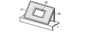
この空気偏向装置15aは、図2に示すように乗りかご側の面と略平行に配置される第1の板体16とこの板体16の頂上部から乗りかごのすれ違い面とは反対側の方向に向かって下降傾斜される第2の板体17とで構成され、第1の板体16と第2の板体17との頂上部接続角は鋭角に形成され、前記上梁1上部ないし釣合いおもりフレームに固定されている。
【0028】
このような構成とすることにより、乗りかごのすれ違い面と反対方向に下降傾斜する空気偏向装置15a,15bを設けているので、すれ違い時の走行空気流が乗りかごのすれ違い面と反対側の方向に合理的に切り分けられ、その下降傾斜面にそって偏向されるので、釣合いおもりフレームから発生する走行空気流の大半が乗りかごとの対向面に入り込むことがなくなり、乗りかごと釣合いおもりフレームとの対向面間に空気乱流が生じにくくなる。このことは、乗りかごと釣合いおもりフレームとの対向面間に生じる空気乱流が小さくなり、それに伴って乗りかごに与える振動や騒音を大幅に低減化できる。
【0029】
さらに、空気偏向装置15aについて詳しく説明する。
【0030】
第1の板体16と第2の板体17は制振材料で構成されるのが望ましく、さらに第2の板体17にはメインロープ8を通過させるための例えば長方形、正方形、楕円等の形状を有するロープ貫通部18が形成され、さらにロープ8の通過部分を除いてロープ貫通部18を閉塞するために第2の板体17上部に貫通部閉塞体20が取り付けられる。
【0031】
この貫通部閉塞体20は、図3に示すように相対する方向からメインロープ8を挟み込む機能をもつ一対の塞ぎ部材20a,20aからなり、この一対の塞ぎ部材20a,20aの相対する面部側には例えば2本のメインロープ8を通過させるための半円状のロープ挿通孔21が形成され、さらに各塞ぎ部材20a,20aの両端側に固定ボルト用穴22が形成され、これら一対の塞ぎ部材20a,20aの固定ボルト用穴22を長尺ボルト23を挿通し、反対側から固定用ナット24で緊締することにより、分割された一対の塞ぎ部材20a,20aを一体的に結合した後、ロープ貫通部18を閉塞するように第2の板体17に固定する。 なお、塞ぎ部材20a,20aは、例えば木製片、ゴム、樹脂、或いはスポンジ等のごとき外力を吸収する部材を用いれば、メインロープ8の振動によって外力が加わった場合でも、ロープ振動によるこすれ音を小さくすることが可能である。
【0032】
従って、乗りかご側とは反対方向に下降傾斜する第2の板体17にロープ貫通部18を形成し、メインロープ8を通過させることにより、メインロープ8の接続部が空気偏向装置15aの内側に配置され、空気偏向装置15aの外側に設けた場合に比較し、空気乱流を小さくできる。さらに、ロープ貫通部18を貫通部閉塞体20で閉塞することにより、当該ロープ貫通部18の空間に走行空気流が浸入することを防止でき、同様に空気乱流を抑制でき、振動の低減化に寄与する。
【0033】
なお、前記第1の板体16と第2の板体17は制振材料で構成するのが望ましいが、この制振材料としては、例えば2種類以上の金属を溶かして混合し、これに高い振動吸収性を付与した複合型、強磁性型、転移型、双晶型、或いは結晶粒界腐食型などの制振合金などが挙げられる。また、制振材料としては、ポリマーを2種類またはそれ以上混合し、耐衝撃性や耐候性などを改良したポリマーアロイ、又はポリマーブレンドに対して制振性を付与した樹脂製の制振樹脂もしくは木粉や木片と制振付与剤としての樹脂を混合し熱成形した木質系制振材料、又は鋼板や石膏ボード、合板等の中間材に対して熱可塑性樹脂シート、熱硬化性樹脂シート等の制振層を配置した複合型サンドイッチ制振材料が用いられる。
【0034】
これら板体16,17を制振材料で構成すれば、これら板体16,17には減衰作用があるので、走行空気流を偏向させた際に急峻な空気流れ振動や風圧外力が作用しても振動を抑制することができ、ひいては振動に伴う騒音を低減化できる。
【0035】
従って、以上のような実施の形態によれば、釣合いおもり装置と乗りかごとのすれ違いによって空気乱流が生じるが、空気偏向装置15a,15bを構成する第1の板体16と第2の板体17が鋭角に設定され、第2の板体17が乗りかごのすれ違い面と反対側の方向に下降傾斜させているので、走行空気流が第2の板体17の傾斜にそって乗りかごと反対方向に合理的に流れるので、乗りかごとの対向面間に巻き込まれる空気量が低減され、よって、空気乱流が生じにくくなり、すれ違いによる乗りかごの振動や騒音を十分に低減できる。
【0036】
なお、空気偏向装置15は、フレームの上部及び下部に設けたが、いずれか一方だけに設けてもよい。また、空気偏向装置15bの構成及び作用についても同様であるので、空気偏向装置15aの説明に譲る。
【0037】
(第2の実施の形態)
図4は本発明に係わるエレベータの釣合いおもり装置の他の実施の形態を示す構成図である。
【0038】
この実施の形態は、フレームの上下部に設けた空気偏向装置15a,15bの他の構成例であって、空気偏向装置15aと15bが同様の構成であるので、以下同様に空気偏向装置15aについて説明する。
【0039】
この空気偏向装置15aは、第1の板体16と第2の板体17を価格的に安価な一般鋼板などの一般構造材で構成する一方、これら板体16,17の表面側又は両面側に貼付け型制振材シート16a,17aを貼り付けた構成である。
【0040】
この貼付け型制振材シート16a,17aとなる制振材料としては、例えば主材に対してプラスチック系、ゴム系、アスファルト系のシート状制振材を接着剤又は粘着材で貼り付けた単層貼付け型制振材料を用いるとか、或いは薄い鋼板等の拘束板とゴム系制振材とを接着剤又は粘着材をもちいて貼り付けた2層貼付け型型制振材料等が用いられる。
【0041】
従って、以上のような実施の形態によれば、一般構造材に貼付け型制振材シート16a,17aを貼り付けた板体16,17を用いることにより、前述する第1の実施の形態と同等の効果を奏する他、第1の実施の形態のような高価な制振材料を用いることなく、部分的に貼り付けすることにより、コストを低減化でき、走行空気流を偏向した際に生じる空気流れ振動や風圧外力を簡便に吸収して減衰させることができ、振動に伴う騒音を低減できる。
【0042】
(第3の実施の形態)
図5は本発明に係わるエレベータの釣合いおもり装置の他の実施の形態を示す構成図である。
【0043】
この実施の形態は、同じく釣合いおもりのフレームの上下部に設けた空気偏向装置15a,15bの他の構成例であって、空気偏向装置15aと15bが同様の構成であるので、以下、空気偏向装置15aについて説明する。
【0044】
第1の実施の形態における空気偏向装置15aでは、第2の板体17に形成されるロープ貫通部18を塞ぐために、第2の板体17上面に貫通部閉塞体20を取り付けられたが、本実施の形態では、第2の板体17に形成されるロープ貫通部18に対し、当該第2の板体17の裏側からロープ貫通部18の切欠き形状と略等しく、かつ、第2の板体17の厚みに相当する凸段差部が形成された塞ぎ部材20b,20bを嵌め込み、各塞ぎ部材20b,20bの適宜な個所をアンカーボルト及び固定ナット24により、第2の板体17に固定する構成である。よって、各塞ぎ部材20b,20bの各凸段差部の面部は第2の板体17の表面と略等しい面位置に設定される。
【0045】
従って、このような実施の形態によれば、貫通部閉塞体20の表面と第2の板体17の面がほぼ同一面となるので、貫通部閉塞体20の上面を通過する走行空気流の乱れを防止でき、空気乱流による振動や騒音の発生を未然に回避することができる。
【0046】
(第4の実施の形態)
図6は本発明に係わるエレベータの釣合いおもり装置の他の実施の形態を示す構成図である。
【0047】
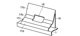
この実施の形態は、第1の板体16の頂上部に接続される第2の板体17の取付け角度や曲面を形成し、第1の板体16と第2の板体17の角度をより鋭角となるように構成したものである。その他の構成は第1の実施の形態と同じである。
【0048】
すなわち、第2の板体17は、第1の板体16の頂上部から乗りかごとのすれ違い面と反対方向に向かって第1の実施の形態よりも多少鋭角となるように下降傾斜させてロープ貫通部18の胴部まで延在される第1の板片17aと、この板片17aの下端部に接続され、ロープ貫通部18の中腹部を形成する部分となる凹曲面状の第2の板片17bと、この第2の板片17bの端部に接続される平板状の第3の板片17cと、この第3の板片17cの端部に接続され、その他端部が例えば梁1に接続される凸曲面状の第4の板片17dとによって構成されている。なお、第2の板体17は、第1の板片17aから第4の板片17dからなるが、第4の板片17dのない構成のものでもよい。
【0049】
従って、以上のような構成の第2の板体17を用いれば、次のような作用を奏するものである。第2の板体17としては、角度の異なる2つ以上の面で構成することにより、第1の板体16と第2の板体17との角度を更に鋭角に形成でき、また空気偏向装置15a,15bの設置高さを小さくできる。このことは、昇降路1の上端及び下端のスペースに応じ、空気偏向装置15a,15bの高さを任意に変更でき、昇降路寸法に配慮した合理的な設計を行うことが可能となる。
【0050】
また、取付け角度の異なる第1の板片17aと第3の片辺17cとの間に曲面の板片17bを接続することにより、空気乱流を更に小さくでき、ひいては空気乱流に伴う振動や騒音を低減できる。
【0051】
(第5の実施の形態)
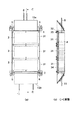
図7は本発明に係わるエレベータの釣合いおもり装置の他の実施の形態を示す構成図であって、乗りかごとのすれ違い面を分り易くする為に、図1で説明した釣合いおもりを反転させた図である。
【0052】
この実施の形態は、乗りかごとのすれ違いによる風圧外力や振動を受け難い釣合いおもりのフレームを構成する例である。
【0053】
フレーム内には積載おもり4が積み重ねられているが、これら積載おもり4表面の多少の凹凸を覆うために複数枚の仕切板31が取付けられるが、これら仕切板31のコーナ部が釣合いおもりフレームに弾性体32を介して固定ボルト33にて固定されている。この弾性体32は、天然ゴム、ブチルゴム、ネオプレンゴム等の主材を用いたゴム弾性体が用いられている。さらに、仕切板31と積載おもり4との間には緩衝材34が配設されている。この緩衝材34は仕切板31の裏面に貼付け又は介在される。
【0054】
前記仕切板31を構成する材料は制振材料が用いられている。この制振材料としては、例えば2種類以上の金属を溶かして混合し、これに高い振動吸収性を付与した複合型、強磁性型、転移型、双晶型、焼結型或いは結晶粒界腐食型などの制振合金の他、ポリマーを2種類又はそれ以上混合し、耐衝撃性や耐候性などを改良したポリマーアロイ、或いはポリマーブレンドに、さらに制振性を付与した樹脂製の制振樹脂もしくは木粉や木片と制振付与剤としての樹脂を混合し熱成形した木質系制振板を用いてもよい。
【0055】
また、緩衝材34としては、例えば発泡型スポンジ、スチレン・ブタジエン系ゴムを主材とした制振発泡型の緩衝材が用いられる。
【0056】
次に、以上のような構成の作用を説明する。
【0057】
乗りかごとのすれ違い面に位置する仕切板31と積載おもり4との間に緩衝材34を配設するとともに、仕切板31を制振材料で構成することにより、仕切板31が減衰吸収作用があるので、すれ違いの際の風圧外力が仕切板31に作用して変形や振動発生要因が生じても、その風の接触音や変形に伴う音を吸収するので、仕切板31からの騒音を低減でき、さらに内部に緩衝材34が設けられているので、風圧外力による変形要因が生じても積載おもり4に伝達されることがなくなり、振動の低減にも寄与させることができる。
【0058】
さらに、上記実施の形態は、仕切板31を制振材料で構成したが、例えば図8に示すように仕切板31を価格的に安価な一般鋼板などの一般構造材で構成する一方、仕切板31の表面側又は両面側には貼付け型制振材シート31aを貼り付けた構成であってもよい。なお、貼付け型制振シートとなる制振材料としては、例えば主材に対してプラスチック系、ゴム系、アスファルト系のシート状制振材を接着剤又は粘着材で貼り付けた単層貼付け型制振材料を用いるとか、或いは薄い鋼板等の拘束板にゴム系制振材を接着剤又は粘着材を貼り付けた2層貼付け型型制振材料等が用いられる。この場合においても、同様な効果を奏することができる。
【0059】
なお、本願発明は、上記実施の形態に限定されるものでなく、その要旨を逸脱しない範囲で種々変形して実施できる。
【0060】
また、各実施の形態は可能な限り組み合わせて実施することが可能であり、その場合には組み合わせによる効果が得られる。さらに、上記各実施の形態には種々の上位,下位段階の発明が含まれており、開示された複数の構成要素の適宜な組み合わせにより種々の発明が抽出され得るものである。例えば問題点を解決するための手段に記載される全構成要件から幾つかの構成要件が省略されうることで発明が抽出された場合には、その抽出された発明を実施する場合には省略部分が周知慣用技術で適宜補われるものである。
【0061】
【発明の効果】
以上説明したように本発明によれば、乗りかごとのすれ違いによる走行空気流を大幅に低減でき、空気乱流に伴う乗りかごへの振動や騒音を確実に低減化できるエレベータの釣合いおもり装置を提供できる。
【図面の簡単な説明】
【図1】本発明に係わるエレベータの釣合いおもり装置の一実施の形態を示す正面図、平面図及び同図(a)のA−A断面図。
【図2】図1に示す空気偏向装置の一例を示す斜視図。
【図3】図2に示す空気偏向装置に使用される貫通部閉塞体の分解斜視図。
【図4】本発明に係わるエレベータの釣合いおもり装置に使用される空気偏向装置の他の例を示す斜視図。
【図5】本発明に係わるエレベータの釣合いおもり装置に使用される空気偏向装置の更に他の例を示す斜視図。
【図6】本発明に係わるエレベータの釣合いおもり装置に使用される空気偏向装置の更に他の例を示す斜視図。
【図7】本発明に係わるエレベータの釣合いおもり装置に使用される積載おもりを覆う仕切板の一例を説明する図。
【図8】本発明に係わるエレベータの釣合いおもり装置に使用される積載おもりを覆う仕切板の表面に制振材シートを貼りつけた一例を説明する図。
【図9】従来の一般的なエレベータの概略構成図。
【図10】従来のエレベータの釣合いおもり装置の正面図。
【図11】従来のエレベータの他の釣合いおもり装置の正面図。
【符号の説明】
1…上梁
2…下梁
3…縦枠
4…積載おもり
6…ガイドローラ
8…メインロープ
11…コンペンロープ
15(15a,15b)…空気偏向装置
16…第1の板体(16a:制振材シート)
17…第2の板体(17a:制振材シート)
18…ロープ貫通部
20…貫通部閉塞体(20a,20b:塞ぎ部材)
31…仕切板
32…弾性体
34…緩衝材[0001]
TECHNICAL FIELD OF THE INVENTION
The present invention relates to an elevator counterweight device that reduces the influence of a passing vehicle on a car.
[0002]
[Prior art]
In the elevator, a hoist (not shown) is installed above the
[0003]
The
[0004]
FIG. 10 is a front view of the counterweight device suspended from the
[0005]
[0006]
On the other hand, the
[0007]
A
[0008]
In the above-described elevator, the
[0009]
As a result, when the
[0010]
In particular, in recent years, with the regeneration of cities, the construction of high-rise buildings and skyscrapers has been increasing, and the speed of raising and lowering the
[0011]
Conventionally, a technique for suppressing air turbulence generated during passing has been proposed. In this prior art, as shown in FIG. 11, a trough-shaped lateral
[0012]
[Patent Document]
Japanese Patent No. 28658894 (FIG. 1)
[0013]
[Problems to be solved by the invention]
However, in the above-described conventional technology, for example, when the
[0014]
The present invention has been made in view of the above circumstances, and has a counterweight device for an elevator that reduces traveling airflow due to passing of a car and reduces vibration and noise in a car due to air turbulence. The purpose is to provide.
[0015]
[Means for Solving the Problems]
(1) In order to solve the above-mentioned problem, an elevator counterweight device according to the present invention includes a rope suspended from one end of a main rope suspended over a sheave of a hoisting machine. A compensating rope end suspended from the lower end of the car and hanged from the lower part of the car via a compensive is connected, and the car is a counterweight device for an elevator that moves up and down in opposite directions,
At least one or both of the upper and lower parts of the counterweight frame on which the weight is mounted, has a downward slope in the direction opposite to the side of the car side, and the traveling air flow generated when passing the car is said. This is a configuration in which an air deflecting device that deflects along a descending inclined surface is provided.
[0016]
Since the present invention is configured as described above, the air deflecting device that is inclined downward in the direction opposite to the passing surface of the car is provided, so that the traveling air flow at the time of passing is opposite to the passing surface of the car. As a result, most of the traveling airflow generated from the counterweight frame does not enter the opposing surface of the car, and as a result, air turbulence does not easily occur between the opposing surfaces of the car and the counterweight device. Therefore, it is possible to reduce the vibration and noise to the car due to the air turbulence.
[0017]
The air deflecting device has a first plate disposed substantially parallel to a surface on a car side, and the car is inclined downward from a top portion of the first plate in an opposite direction. And the second plate body arranged in such a manner that the traveling air flow generated in the projected cross-sectional area in the moving direction of the counterweight frame is rationally deflected to a surface opposite to the passing surface of the car. It is possible to do.
[0018]
In addition, the second plate body is formed by cutting the second plate body, except for a rope penetrating portion for penetrating a rope and a rope penetrating portion penetrating the rope penetrating portion. When the rope is disposed outside the air deflecting device by providing the penetrating portion closing body mounted on the second plate body so as to close the portion, the rope passes through the rope penetrating portion in the air deflecting device. Air turbulence can be reduced as compared to that of the above, and the rope penetration can be prevented from entering the space of the rope penetration by closing the rope penetration with the obstruction except for the rope penetration. Can be smaller.
[0019]
Furthermore, if the surface position of the through-portion closing body is substantially equal to that of the second plate body, the deflected traveling airflow can smoothly pass over the upper surface of the through-portion closing body, and the air turbulence is not disturbed. It is possible to allow air to flow over the car and the surface in the opposite direction.
[0020]
(2) Further, according to the present invention, if a partition plate is arranged on the side of the counterweight of the counterweight mounted on the counterweight frame so as to cover the weight via a cushioning material, the external wind pressure at the time of passing can be reduced. Even if the partition plate is deformed by acting on it, it is possible to absorb and attenuate the wind pressure collision sound and the sound accompanying the deformation beforehand.
[0021]
(3) In addition, the present invention provides a traveling system in which one or both of the first plate body, the second plate body, and the partition plate are attached to a vibration damping material or a general structural material surface with a vibration damping material sheet. Even if a steep wind pressure external force acts when the air flow is deflected, the vibration can be suppressed, and the noise accompanying the vibration can be reduced.
[0022]
BEST MODE FOR CARRYING OUT THE INVENTION
Hereinafter, embodiments of the present invention will be described with reference to the drawings.
[0023]
(First Embodiment)
FIG. 1 is a configuration diagram showing an embodiment of an elevator counterweight device according to the present invention. 1A is a front view, FIG. 1B is a plan view, and FIG. 1C is a cross-sectional view taken along line AA of FIG. 1A.
[0024]
This counterweight device has an
[0025]
[0026]
Further, an air deflecting device 15 (15a, 15b) for deflecting air to a surface opposite to a passing surface of the car is attached to an upper portion of the
[0027]
As shown in FIG. 2, the
[0028]
With such a configuration, the
[0029]
Further, the
[0030]
The
[0031]
As shown in FIG. 3, the penetrating
[0032]
Therefore, the
[0033]
It is desirable that the
[0034]
If these
[0035]
Therefore, according to the above-described embodiment, air turbulence occurs due to passing of the counterweight device and the car, but the
[0036]
The air deflecting device 15 is provided on the upper and lower portions of the frame, but may be provided on only one of them. Since the configuration and operation of the
[0037]
(Second embodiment)
FIG. 4 is a configuration diagram showing another embodiment of the elevator counterweight device according to the present invention.
[0038]
This embodiment is another example of the configuration of the
[0039]
In the
[0040]
As a vibration damping material to be the pasting-type damping
[0041]
Therefore, according to the above-described embodiment, by using the
[0042]
(Third embodiment)
FIG. 5 is a configuration diagram showing another embodiment of the elevator counterweight device according to the present invention.
[0043]
This embodiment is another example of the structure of the
[0044]
In the
[0045]
Therefore, according to such an embodiment, the surface of the through-
[0046]
(Fourth embodiment)
FIG. 6 is a configuration diagram showing another embodiment of an elevator counterweight device according to the present invention.
[0047]
In this embodiment, the mounting angle and the curved surface of the
[0048]
That is, the
[0049]
Therefore, the use of the
[0050]
Further, by connecting the
[0051]
(Fifth embodiment)
FIG. 7 is a block diagram showing another embodiment of the elevator counterweight device according to the present invention, in which the counterweight described in FIG. FIG.
[0052]
This embodiment is an example in which a frame of a counterweight which is hardly subjected to external wind pressure and vibration due to passing each other is configured.
[0053]
The
[0054]
The material constituting the
[0055]
Further, as the cushioning
[0056]
Next, the operation of the above configuration will be described.
[0057]
The cushioning
[0058]
Further, in the above embodiment, the
[0059]
The present invention is not limited to the above-described embodiment, and can be implemented with various modifications without departing from the scope of the invention.
[0060]
Further, the embodiments can be implemented in combination as much as possible, and in that case, the effect of the combination can be obtained. Furthermore, each of the above embodiments includes various upper and lower stage inventions, and various inventions can be extracted by appropriately combining a plurality of disclosed components. For example, when an invention is extracted because some constituent elements can be omitted from all the constituent elements described in the means for solving the problem, if the extracted invention is implemented, the omitted part is omitted. Is appropriately supplemented by well-known conventional techniques.
[0061]
【The invention's effect】
As described above, according to the present invention, there is provided an elevator counterweight device that can significantly reduce traveling airflow due to passing of a car and can surely reduce vibration and noise of the car due to air turbulence. Can be provided.
[Brief description of the drawings]
FIG. 1 is a front view, a plan view, and an AA sectional view of FIG. 1 (a) showing an embodiment of an elevator counterweight device according to the present invention.
FIG. 2 is a perspective view showing an example of the air deflection device shown in FIG.
FIG. 3 is an exploded perspective view of a through-hole closing body used in the air deflection device shown in FIG. 2;
FIG. 4 is a perspective view showing another example of the air deflecting device used in the elevator counterweight device according to the present invention.
FIG. 5 is a perspective view showing still another example of the air deflecting device used in the elevator counterweight device according to the present invention.
FIG. 6 is a perspective view showing still another example of the air deflection device used in the elevator counterweight device according to the present invention.
FIG. 7 is a diagram illustrating an example of a partition plate that covers a loading weight used in the elevator counterweight device according to the present invention.
FIG. 8 is a diagram illustrating an example in which a vibration damping material sheet is attached to a surface of a partition plate that covers a loading weight used in an elevator counterweight device according to the present invention.
FIG. 9 is a schematic configuration diagram of a conventional general elevator.
FIG. 10 is a front view of a conventional elevator counterweight device.
FIG. 11 is a front view of another counterweight device of the conventional elevator.
[Explanation of symbols]
DESCRIPTION OF
17: second plate (17a: vibration damping material sheet)
18 ...
31 ...
Claims (8)
おもりが装着された釣合いおもりフレームの上部及び下部の何れか一方又は両方に、前記乗りかご側の面と反対側の方向に下降傾斜を有し、前記乗りかごとのすれ違い時に発生する走行空気流を前記下降傾斜面に沿って偏向させる空気偏向装置を設けたことを特徴とするエレベータの釣合いおもり装置。The car suspended from one end of the main rope suspended over the sheave of the hoist is suspended from the rope end on the opposite side, and is suspended from the lower part of the car via a compensive sheave. The end of the handed compensope is connected, and the car is lifted and lowered in opposite directions.
A traveling airflow generated when one or both of the upper part and the lower part of the counterweight frame with the weight mounted thereon has a downward inclination in a direction opposite to the surface on the car side, and occurs when the cars pass each other. An air deflecting device for deflecting the air along the descending inclined surface.
前記第2の板体は、当該第2の板体が切り欠かれ、前記ロープを貫通させるためのロープ貫通部と、このロープ貫通部を貫通する前記ロープの貫通部分を除き、当該ロープ貫通部を塞ぐように前記第2の板体上に取付けた貫通部閉塞体とを設けたことを特徴とするエレベータの釣合いおもり装置。The elevator counterweight device according to claim 2 or claim 3,
The second plate body is formed by cutting out the second plate body, and excluding a rope penetration part for penetrating the rope and a rope penetration part penetrating the rope penetration part. And a through-hole closing member mounted on the second plate so as to close the second plate.
前記第2の板体は、当該第2の板体が切り欠かれ、前記ロープを貫通させるためのロープ貫通部と、前記第2の板体の裏側から前記ロープ貫通部に対して嵌め込み式とし、かつ、当該第2の板体の表面と略等しい面位置となるように形成された貫通部閉塞体とを設けたことを特徴とするエレベータの釣合いおもり装置。The elevator counterweight device according to claim 2 or claim 3,
The second plate is cut into the second plate, and has a rope penetrating portion through which the rope penetrates, and is fitted into the rope penetrating portion from the back side of the second plate. And a penetrating portion closing body formed so as to have a surface position substantially equal to the surface of the second plate body.
前記第1の板体、第2の板体及び前記仕切板の何れか一方又は両方を制振材料又は一般構造材面に制振材シートを貼り付けたことを特徴とするエレベータの釣合いおもり装置。The elevator counterweight device according to any one of claims 2 to 4, and claim 6,
An elevator counterweight device wherein one or both of the first plate, the second plate, and the partition plate are attached to a damping material or a general structural material surface with a damping material sheet. .
Priority Applications (1)
| Application Number | Priority Date | Filing Date | Title |
|---|---|---|---|
| JP2002370531A JP4285988B2 (en) | 2002-12-20 | 2002-12-20 | Elevator counterweight device |
Applications Claiming Priority (1)
| Application Number | Priority Date | Filing Date | Title |
|---|---|---|---|
| JP2002370531A JP4285988B2 (en) | 2002-12-20 | 2002-12-20 | Elevator counterweight device |
Publications (2)
| Publication Number | Publication Date |
|---|---|
| JP2004196533A true JP2004196533A (en) | 2004-07-15 |
| JP4285988B2 JP4285988B2 (en) | 2009-06-24 |
Family
ID=32766422
Family Applications (1)
| Application Number | Title | Priority Date | Filing Date |
|---|---|---|---|
| JP2002370531A Expired - Lifetime JP4285988B2 (en) | 2002-12-20 | 2002-12-20 | Elevator counterweight device |
Country Status (1)
| Country | Link |
|---|---|
| JP (1) | JP4285988B2 (en) |
Cited By (8)
| Publication number | Priority date | Publication date | Assignee | Title |
|---|---|---|---|---|
| US8098869B2 (en) | 2005-01-24 | 2012-01-17 | Panasonic Corporation | Loudspeaker damper, manufacturing method thereof, and loudspeaker and electronic device using the same |
| CN104229605A (en) * | 2013-06-24 | 2014-12-24 | 株式会社日立制作所 | Counterweight and elevator device |
| CN104860168A (en) * | 2014-02-24 | 2015-08-26 | 株式会社日立制作所 | Elevator Device |
| US20160031677A1 (en) * | 2013-02-04 | 2016-02-04 | Kone Corporation | Elevator |
| CN105668396A (en) * | 2014-12-05 | 2016-06-15 | 株式会社日立制作所 | Elevator device |
| CN105819312A (en) * | 2015-01-22 | 2016-08-03 | 株式会社日立制作所 | Elevator device and elevator device assembling method |
| US9908746B2 (en) | 2015-07-13 | 2018-03-06 | Otis Elevator Company | Elevator system sound reducing assembly and method |
| EP3398894A1 (en) * | 2017-05-05 | 2018-11-07 | KONE Corporation | Elevator system and counterweight screen |
Families Citing this family (1)
| Publication number | Priority date | Publication date | Assignee | Title |
|---|---|---|---|---|
| CN105174006A (en) * | 2015-09-21 | 2015-12-23 | 合肥市迅立达电梯有限公司 | Counterweight device for elevator |
-
2002
- 2002-12-20 JP JP2002370531A patent/JP4285988B2/en not_active Expired - Lifetime
Cited By (11)
| Publication number | Priority date | Publication date | Assignee | Title |
|---|---|---|---|---|
| US8098869B2 (en) | 2005-01-24 | 2012-01-17 | Panasonic Corporation | Loudspeaker damper, manufacturing method thereof, and loudspeaker and electronic device using the same |
| US20160031677A1 (en) * | 2013-02-04 | 2016-02-04 | Kone Corporation | Elevator |
| US9725283B2 (en) * | 2013-02-04 | 2017-08-08 | Kone Corporation | Elevator |
| CN104229605A (en) * | 2013-06-24 | 2014-12-24 | 株式会社日立制作所 | Counterweight and elevator device |
| CN104860168A (en) * | 2014-02-24 | 2015-08-26 | 株式会社日立制作所 | Elevator Device |
| CN105668396A (en) * | 2014-12-05 | 2016-06-15 | 株式会社日立制作所 | Elevator device |
| CN105819312A (en) * | 2015-01-22 | 2016-08-03 | 株式会社日立制作所 | Elevator device and elevator device assembling method |
| US9908746B2 (en) | 2015-07-13 | 2018-03-06 | Otis Elevator Company | Elevator system sound reducing assembly and method |
| EP3398894A1 (en) * | 2017-05-05 | 2018-11-07 | KONE Corporation | Elevator system and counterweight screen |
| CN108792907A (en) * | 2017-05-05 | 2018-11-13 | 通力股份公司 | Elevator device and counterweight screen |
| US10919731B2 (en) | 2017-05-05 | 2021-02-16 | Kone Corporation | Elevator system and counterweight screen |
Also Published As
| Publication number | Publication date |
|---|---|
| JP4285988B2 (en) | 2009-06-24 |
Similar Documents
| Publication | Publication Date | Title |
|---|---|---|
| AU753682B2 (en) | Cable elevator with a drive plate | |
| EP1405813B1 (en) | Elevator device | |
| JP2004196533A (en) | Counterweight device for elevator | |
| JP4673746B2 (en) | Elevator car assembly with adjustable platform | |
| JP4146004B2 (en) | Elevator equipment | |
| JPH06329372A (en) | Elevator device | |
| JP5142465B2 (en) | Pulley device for elevator | |
| CN209275948U (en) | A kind of Lift car type elevator of damping noise reduction | |
| AU4450999A (en) | Device for reducing wind noise in fast moving elevators cars | |
| JP6058149B2 (en) | Elevator car | |
| WO2011155109A1 (en) | Elevator cage | |
| JP2528437Y2 (en) | Elevator shock absorber | |
| JP2005511449A (en) | Elevator noise / vibration isolation system | |
| WO2001074704A1 (en) | Machine-room-less elevator installation structure with traction machine mounted at a rooftop | |
| JP5241205B2 (en) | Elevator plate | |
| JP3700412B2 (en) | Traction elevator | |
| CN214003743U (en) | Multiple absorbing no computer lab elevator | |
| JP4434456B2 (en) | Elevator rail bracket | |
| JP2004262602A (en) | Car for elevator | |
| JP2001106460A (en) | Elevator car | |
| JP3806573B2 (en) | Guide rail support structure for elevator equipment | |
| JP2004123273A (en) | Elevator passenger car | |
| CN210763806U (en) | Right-angle through type traction elevator | |
| KR100455502B1 (en) | Installation structure of elevator traction machine | |
| JP5080634B2 (en) | Double deck elevator |
Legal Events
| Date | Code | Title | Description |
|---|---|---|---|
| A621 | Written request for application examination |
Free format text: JAPANESE INTERMEDIATE CODE: A621 Effective date: 20051027 |
|
| A977 | Report on retrieval |
Free format text: JAPANESE INTERMEDIATE CODE: A971007 Effective date: 20080730 |
|
| A131 | Notification of reasons for refusal |
Effective date: 20080805 Free format text: JAPANESE INTERMEDIATE CODE: A131 |
|
| A521 | Written amendment |
Effective date: 20081003 Free format text: JAPANESE INTERMEDIATE CODE: A523 |
|
| A02 | Decision of refusal |
Effective date: 20081104 Free format text: JAPANESE INTERMEDIATE CODE: A02 |
|
| A521 | Written amendment |
Effective date: 20081204 Free format text: JAPANESE INTERMEDIATE CODE: A523 |
|
| A911 | Transfer of reconsideration by examiner before appeal (zenchi) |
Free format text: JAPANESE INTERMEDIATE CODE: A911 Effective date: 20090116 |
|
| TRDD | Decision of grant or rejection written | ||
| A01 | Written decision to grant a patent or to grant a registration (utility model) |
Free format text: JAPANESE INTERMEDIATE CODE: A01 Effective date: 20090310 |
|
| A01 | Written decision to grant a patent or to grant a registration (utility model) |
Free format text: JAPANESE INTERMEDIATE CODE: A01 |
|
| A61 | First payment of annual fees (during grant procedure) |
Effective date: 20090324 Free format text: JAPANESE INTERMEDIATE CODE: A61 |
|
| FPAY | Renewal fee payment (prs date is renewal date of database) |
Free format text: PAYMENT UNTIL: 20120403 Year of fee payment: 3 |
|
| R150 | Certificate of patent (=grant) or registration of utility model |
Free format text: JAPANESE INTERMEDIATE CODE: R150 |
|
| FPAY | Renewal fee payment (prs date is renewal date of database) |
Free format text: PAYMENT UNTIL: 20120403 Year of fee payment: 3 |
|
| FPAY | Renewal fee payment (prs date is renewal date of database) |
Year of fee payment: 4 Free format text: PAYMENT UNTIL: 20130403 |
|
| FPAY | Renewal fee payment (prs date is renewal date of database) |
Year of fee payment: 4 Free format text: PAYMENT UNTIL: 20130403 |
|
| FPAY | Renewal fee payment (prs date is renewal date of database) |
Year of fee payment: 5 Free format text: PAYMENT UNTIL: 20140403 |
|
| S531 | Written request for registration of change of domicile |
Free format text: JAPANESE INTERMEDIATE CODE: R313531 |
|
| R350 | Written notification of registration of transfer |
Free format text: JAPANESE INTERMEDIATE CODE: R350 |