JP2004196077A - Tire air pressure monitoring device - Google Patents
Tire air pressure monitoring device Download PDFInfo
- Publication number
- JP2004196077A JP2004196077A JP2002365556A JP2002365556A JP2004196077A JP 2004196077 A JP2004196077 A JP 2004196077A JP 2002365556 A JP2002365556 A JP 2002365556A JP 2002365556 A JP2002365556 A JP 2002365556A JP 2004196077 A JP2004196077 A JP 2004196077A
- Authority
- JP
- Japan
- Prior art keywords
- tire pressure
- vehicle
- unit
- tire
- output
- Prior art date
- Legal status (The legal status is an assumption and is not a legal conclusion. Google has not performed a legal analysis and makes no representation as to the accuracy of the status listed.)
- Granted
Links
Images


Classifications
-
- B—PERFORMING OPERATIONS; TRANSPORTING
- B60—VEHICLES IN GENERAL
- B60C—VEHICLE TYRES; TYRE INFLATION; TYRE CHANGING; CONNECTING VALVES TO INFLATABLE ELASTIC BODIES IN GENERAL; DEVICES OR ARRANGEMENTS RELATED TO TYRES
- B60C23/00—Devices for measuring, signalling, controlling, or distributing tyre pressure or temperature, specially adapted for mounting on vehicles; Arrangement of tyre inflating devices on vehicles, e.g. of pumps or of tanks; Tyre cooling arrangements
- B60C23/02—Signalling devices actuated by tyre pressure
- B60C23/04—Signalling devices actuated by tyre pressure mounted on the wheel or tyre
- B60C23/0408—Signalling devices actuated by tyre pressure mounted on the wheel or tyre transmitting the signals by non-mechanical means from the wheel or tyre to a vehicle body mounted receiver
-
- B—PERFORMING OPERATIONS; TRANSPORTING
- B60—VEHICLES IN GENERAL
- B60C—VEHICLE TYRES; TYRE INFLATION; TYRE CHANGING; CONNECTING VALVES TO INFLATABLE ELASTIC BODIES IN GENERAL; DEVICES OR ARRANGEMENTS RELATED TO TYRES
- B60C23/00—Devices for measuring, signalling, controlling, or distributing tyre pressure or temperature, specially adapted for mounting on vehicles; Arrangement of tyre inflating devices on vehicles, e.g. of pumps or of tanks; Tyre cooling arrangements
- B60C23/02—Signalling devices actuated by tyre pressure
- B60C23/04—Signalling devices actuated by tyre pressure mounted on the wheel or tyre
- B60C23/0401—Signalling devices actuated by tyre pressure mounted on the wheel or tyre characterised by the type of alarm
Abstract
Description
【0001】
【発明の属する技術分野】
この発明は、タイヤ空気圧監視装置に関する。
【0002】
【従来の技術】
自動車(車両)のユーザにとって、始業点検の際、エンジンオイルやラジエータ冷却液の残量などは目視によって外部から容易に確認することができるが、タイヤの空気圧が適正か否かは外部から確認することが困難である。
【0003】
その意図から特公昭43−17766号公報において、車両のタイヤに圧力応動電気スイッチと、送信アンテナを含む小型発振器などからなるセンサユニットを取りつけ、タイヤ空気圧が所定値以下に低下した場合に発振器を作動させて出力を送信させると共に、運転席付近に受信アンテナを含む監視ユニットを設けて前記出力を受信するようにしたタイヤ空気圧監視装置が提案されている。
【0004】
また、タイヤ空気圧検出手法としては、上記の他、特開2000─142043号で提案されるように圧力センサを用いてタイヤ空気圧を直接的に検出する手法や、特開平6−92114号公報で提案されるようにABS(Antilock BrakeSystem) 用の車輪速センサの出力から推定することも良く知られている。
【0005】
【発明が解決しようとする課題】
上記した従来技術によってタイヤ空気圧の低下が確認された場合、その事実は運転席ダッシュボードのインディケータなどに表示される。従って、ユーザは車から降りて空気圧が低下したタイヤの空気を充填することになるが、そのとき、作業前に充填が必要なタイヤを確認するには、イグニション・スイッチを再度オンしてインディケータを表示動作させる必要があった。
【0006】
従って、この発明は上記した不都合を解消し、ユーザが空気圧が不足したタイヤに空気を充填するときの作業を容易にするようにしたタイヤ空気圧監視装置を提供することにある。
【0007】
【課題を解決するための手段】
上記の目的を達成するために、この発明は、請求項1項において、車両に装着された複数個のタイヤのそれぞれに配置され、タイヤ空気圧を示す出力を生じる圧力センサと前記圧力センサの出力を送信する送信アンテナとを少なくとも含むセンサユニットと、前記車両に搭載され、前記センサユニットから送信される出力を受信アンテナを介して受信して所定値と比較して前記タイヤの空気圧が適正か否か判定し、判定結果を報知部に表示する監視ユニットと、前記車両に搭載され、イグニション・スイッチを介して前記報知部に動作電源を供給する車載バッテリ電源とを備えたタイヤ空気圧監視装置において、前記車両の室内に配置され、ユーザの操作によって前記車載バッテリ電源を前記イグニション・スイッチを迂回して前記報知部に接続し、前記報知部に動作電源を供給する操作スイッチを備える如く構成した。
【0008】
車両の室内に配置され、ユーザの操作によって車載バッテリ電源をイグニション・スイッチを迂回して報知部に接続し、報知部に動作電源を供給する操作スイッチを備える如く構成したので、ユーザが車から降りて空気圧が低下したタイヤの空気を充填する場合、イグニション・スイッチをオンすることなく、車室内の操作スイッチを操作するだけで、インディケータを表示動作させて充填が必要なタイヤを確認することができるので、空気充填作業が容易となる。
【0009】
請求項2項にあっては、車両に装着された複数個のタイヤのそれぞれに配置され、タイヤ空気圧を示す出力を生じる圧力センサと前記圧力センサの出力を送信する第1の送信アンテナとを少なくとも含むセンサユニットと、前記車両に搭載され、前記センサユニットから送信される出力を第1の受信アンテナを介して受信して所定値と比較して前記タイヤの空気圧が適正か否か判定し、判定結果を第1の報知部に表示する監視ユニットとを備えたタイヤ空気圧監視装置において、前記監視ユニットに配置される第2の送信アンテナと、前記車両の外部でユーザによって所持される携帯端末装置と、前記携帯端末装置に配置される第2の受信アンテナと、前記携帯端末装置に設けられる第2の報知部とを備えると共に、前記監視ユニットは、前記ユーザの指示に従って前記第2の送信アンテナと第2の受信アンテナを介して前記判定結果を前記タイヤの空気圧の状態を含めて前記第2の報知部に表示させる如く構成した。
【0010】
車両の外部でユーザによって所持される携帯端末装置に設けられる第2の報知部を備えると共に、監視ユニットがユーザの指示に従って第2の送信アンテナと第2の受信アンテナを介して判定結果をタイヤの空気圧の状態を含めてその第2の報知部に表示させる如く構成したので、ユーザが車から降りて空気圧が低下したタイヤの空気を充填する場合、同様にイグニション・スイッチをオンすることなく、ユーザが指示するだけで携帯端末装置の報知部に判定結果が表示されるので、空気充填作業が容易となる。
【0011】
また、携帯端末装置の報知部には判定結果がタイヤの空気圧の状態を含めて表示されるので、ユーザは報知部の表示によってタイヤ空気圧の過不足状態を認識して調整することができるため、空気充填作業が一層容易となる。
【0012】
請求項3項にあっては、前記監視ユニットは、前記判定の結果が、前記タイヤの空気圧が適正ではないことを示すとき、前記空気圧の調整方向も表示させる如く構成した。
【0013】
監視ユニットは、判定の結果がタイヤの空気圧が適正ではないことを示すとき、空気圧の調整方向、即ち、空気を充填すべきか、抜くべきかも表示させる如く構成したので、空気充填作業がより一層容易となる。
【0014】
請求項4項にあっては、前記携帯端末装置が、リモートキーレスエントリ、携帯電話機およびPHS電話機の中のいずれかである如く構成した。
【0015】
携帯端末装置が、リモートキーレスエントリ、携帯電話機およびPHS電話機の中のいずれかであるように構成したので、ユーザはリモートキーレスエントリなどを手元に置いて空気充填作業を行うことができるため、作業が一層容易となる。
【0016】
【発明の実施の形態】
以下、添付図面に即してこの発明の実施の形態を説明する。
【0017】
図1はその一つの実施の形態に係るタイヤ空気圧監視装置を全体的に示す概略説明図である。
【0018】
符号10はそのタイヤ空気圧監視装置を示し、タイヤ空気圧監視装置10は、車両12に装着された符号14で総称する4個(複数個)のタイヤのそれぞれに配置された、符号16で総称する4個のセンサユニットと、車両12の室内の適宜位置に搭載される1個の監視ユニット20を備える。尚、4個のタイヤ14およびそれに対応するセンサユニット16は、具体的には、図示の如く、前右側FRを14FRあるいは16FR、後右側RRを14RRあるいは16RR、前左側FLを14FLあるいは16FL、後左側RLを14RLあるいは16RLで示す。
【0019】
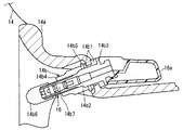
図2はセンサユニット16の構造を示す説明断面図である。
【0020】
図示の如く、センサユニット16は、金属製のホイールディスク(リム)14aに装着された空気注入用のバルブ14bと一体的に構成される。ホイールディスク14aとバルブ14bの間にはグロメット(ブッシュ)14b1が介挿され、バルブ14bのステム14b2の外周に突出して形成されるフランジ部14b3と、ナット14b4(およびワッシャ14b5)でグロメット14b1を挟持することにより、バルブ14bは図示位置に固定される。バルブ14bは、ホイールディスク14aの内部側において拡大され、そこにセンサユニット16の本体16aが接続される。尚、符号14b6はキャップを、14b7は空気充填用のバルブコアを示す。
【0021】
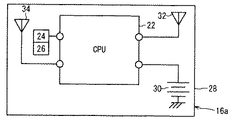
図3は、センサユニット16の本体16aの構成を詳細に示すブロック図である。
【0022】
センサユニット16の本体16aは、CPU22と、ホイールディスク14aの内部の空気圧、即ち、タイヤ空気圧を示す出力を生じる圧力センサ24と、その部位の温度を示す出力を生じる温度センサ26を備える。センサ24,26の出力は、A/D変換回路(図示せず)を介してデジタル値に変換され、CPU22に入力される。尚、CPU22および圧力センサ24などの構成部品は、1枚の回路基板28の上に一体的に搭載されてワンチップ化される。
【0023】
また、本体16aには、電源(リチウム電池。バッテリ電源)30が配置されてCPU22の動作電源として機能する。また、本体16aには送信アンテナ32と受信アンテナ34が設けられて圧力センサ24と温度センサ26の出力を監視ユニット20に送信する一方、監視ユニット20からの送信を受信する。
【0024】
図示は省略するが、電源30とCPU22の間の電源回路の適宜位置には電圧センサが設けられ、電源30の出力電圧に応じた信号を出力する。電圧センサの出力もA/D変換され、CPU22に入力される。
【0025】
図1の説明に戻ると、監視ユニット20は、車室内の適宜位置に配置されてハウジング20a内に収容された本体20b(図1で図示省略)と、タイヤ14のそれぞれの付近に配置された、符号40で総称する4個の受信アンテナと、符号42で総称する4個の送信アンテナを備える。即ち、監視ユニット20は、タイヤ14FRから14RLに対応して配置された送信アンテナ40FRから40RLと、受信アンテナ42FRから42RLを備える。受信アンテナ40と送信アンテナ42は、同軸ケーブル44を介してハウジング20a内の本体20bに接続される。
【0026】
さらに、監視ユニット20は、車両12の運転席のダッシュボードに配置されたインディケータ(第1の報知部)46を備える。インディケータ46と監視ユニット20のハウジング20a内の本体20bは、ハーネス48を介して接続される。
【0027】
符号50は、車両12の外部で図示のユーザによって所持される携帯端末装置、具体的にはリモートキーレスエントリ、携帯電話機およびPHS電話機の中のいずれか、より具体的には、車両12のドアのロック信号およびアンロック信号を送信する送信アンテナを内蔵するリモートキーレスエントリを示す。尚、携帯端末装置は、ユーザによって車両12の外部で所持可能なものであれば、上記に限られるものではない。
【0028】
図4は、監視ユニット20の本体20bなどの構成を詳細に示す説明ブロック図である。
【0029】
図示の如く、監視ユニット20の本体20bは、CPU52を備える。CPU52も、センサユニット16の本体16aと同様、1枚の回路基板54の上に搭載されてワンチップ化される。CPU52は、前記した受信アンテナ40を介してセンサユニット16からのデータを受信すると共に、送信アンテナ42を介して後述するようにデータを送信する。
【0030】
インディケータ46は、第1、第2の警告灯46a,46bと、5個の表示パネル46c,46d,46e,46f,46gを備える。インディケータ46は、前記したように、本体20bに接続、より詳しくはそのCPU52に接続される。
【0031】
図5は、監視ユニット20、より正確にはその本体20bのCPU52の動作を機能的に示す説明ブロック図である。
【0032】
CPU52は、センサユニット16から送信アンテナ32を介して送信された、4個のタイヤ14についての空気圧を示す信号を受信アンテナ40を介して入力し、空気圧比較ブロック52aで入力値を第1の所定値と比較する。第1の所定値としては、推奨値(Recommended Cold Pressure 。車両12が放置されてタイヤ14が冷却しきったときの値で、車種により予め設定される値)を1.3倍して得た値を使用する。
【0033】
CPU52は、空気圧比較ブロック52aにおいて4個のタイヤの1つまたは2以上に関する入力値が第1の所定値以上と判断されるとき、そのタイヤが過剰空気圧と判定し、点灯指示信号(報知指示信号)をインディケータ46に出力し、第1の警告灯46aを点灯させると共に、アンテナ42,34を介してセンサユニット16に送信周期切り換え信号(後述)を出力する。
【0034】
尚、CPU52は点灯指示信号を出力して第1の警告灯46aを点灯させるとき、パネル46cに図示される車両図形の4個のタイヤ部分図の中の対応するものを表示させる。尚、報知手段として視覚的に報知するインディケータ46を用いたが、音声で表示するスピーカ、ブザーなどを用いても良く、さらには両者を用いても良い。
【0035】
CPU52は、空気圧比較ブロック52aで入力値(検出タイヤ空気圧)が第1の所定値未満と判断されるときは警報判定ブロック52bにおいて入力値を第2の所定値と比較する。第2の所定値としては、推奨値を0.8倍して得た値を使用する。
【0036】
CPU52は、警報判定ブロック52bで入力値が第2の所定値未満と判定されるとき、同様に点灯指示信号を出力し、第1の警告灯46aを点灯させると共に、アンテナ42,34を介してセンサユニット16に送信周期切り換え信号を出力する。
【0037】
他方、CPU52は、入力値が第2の所定値以上と判定されるとき、消灯指示信号を出力して第1の警告灯46aを消灯させる。これは、空気圧比較ブロック52aで入力値が第1の所定値未満と判定された場合も同様である。
【0038】
さらに、CPU52は、センサユニット16からアンテナ32,40を介して送信された、4個のタイヤ14についてのホイールディスク14a内の温度、即ち、タイヤ温度を示す温度センサ26の出力を入力し、温度比較ブロック52cで入力値を所定温度(例えば80℃)と比較する。
【0039】
CPU52は、温度比較ブロック52cにおいて4個のタイヤの1つまたは2以上に関する入力値が所定温度以上と判断されるときは点灯指示信号を出力し、第1の警告灯46aを点灯させると共に、入力値が所定温度未満と判断されるときは消灯信号を出力し、第1の警告灯46aを消灯させる。
【0040】
さらに、CPU52は、センサユニット16からアンテナ32,40を介して送信された電源30の出力電圧を示す電圧センサの出力を入力し、電圧比較ブロック52dで入力値を所定電圧(例えば1.8V)と比較する。
【0041】
CPU52は、電圧比較ブロック52dにおいて入力値が所定電圧未満と判断されるときは点灯指示信号を出力し、第2の警告灯46bを点灯させると共に、入力値が所定電圧以上と判断されるときは消灯指示信号を出力し、第2の警告灯46bを消灯させる。
【0042】
ここで、動作電源について説明すると、図4に示す如く、監視ユニット20において、インディケータ46は車両12に搭載された車載バッテリ電源56にイグニション・スイッチ58を介して接続され、ユーザがイグニション・スイッチ58をオンしたとき、通電されて動作(表示)電源を供給される。
【0043】
それに対し、監視ユニット20において、CPU52は、車載バッテリ電源56に定電源回路62を介して常時接続される。前記したように、センサユニット16の電源30はリチウム電池であることから、センサユニット16はタイヤ空気圧などを示す出力を、イグニション・スイッチ58がオフ、即ち、車両12のエンジン(図示せず)が停止されるときも検出(測定)して送信すると共に、監視ユニット20も常時その送信を受信して後述するようにタイヤ空気圧などが適正か否か判定する。
【0044】
また、車載バッテリ電源56とインディケータ46の間の電源回路には、イグニション・スイッチ58に並列して操作スイッチ64が介挿される。操作スイッチ64は、図1に示す如く、車両12の室内、即ち、運転席のダッシュボードに配置されたインディケータ46に隣接して配置され、ユーザが操作できるように配置される。ユーザの操作によって操作スイッチ64がオンされると、イグニション・スイッチ58を迂回して車載バッテリ電源56をインディケータ46に接続し、インディケータ46に動作電源を供給するように構成される。
【0045】
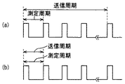
図6は、CPU52のタイヤ空気圧などの検出・送信動作を示すタイム・チャートである。
【0046】
同図(a)は、タイヤの空気圧が適正な状態、即ち、少なくともタイヤ空気圧が第1の所定値未満で第2の所定値以上の状態にある場合のタイム・チャートである。尚、タイヤ空気圧が適正な状態にあることに加え、タイヤ温度が所定温度未満である場合を、タイヤ空気圧が適正な状態とみなしても良い。
【0047】
そのような適正な場合にあっては、センサユニット16においてCPU22は測定周期(例えば7.0sec)ごとにセンサ出力をA/D変換して入力する(読み込む)と共に、送信周期(例えば4.0minから8.0min)ごとに入力値(検出値)を監視ユニット20に送信する。尚、送信周期は4個のセンサユニット16ごとに僅かずつずらされる。
【0048】
尚、センサユニット16の送信アンテナ32から監視ユニット20の受信アンテナ40を介してのデータ送信は、周波数は315MHzで行われる。また、後述するように、監視ユニット20の送信アンテナ42からセンサユニット16の受信アンテナ34を介してのデータ送信も、同一の周波数で行われる。
【0049】
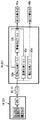
また、センサユニット16からの送信データは、図7に示すように、IDパルス列(後述)、およびその他の圧力センサ出力(デジタル変換値)、温度センサ出力(デジタル変換値)および電圧センサ出力(デジタル変換値)を示すパルス列の順で結合された、例えば56ビットの信号(IDパルス列が32ビット、圧力センサ出力、温度センサ出力および電圧センサ出力を示すパルス列がそれぞれ8ビット)を1単位として構成される。
【0050】
IDパルス列は同図の下部に示すように、4個のセンサユニット16が対応する、1セット分(4個)のタイヤ14のそれぞれに個別に添付されるバーコードからなる。即ち、バーコードは、車両12を工場から出荷するとき、前記した14FLなどの4個のタイヤごとに別々に付与されると共に、車両12が異なるときは別々に付与される。従って、1つのバーコード(IDパルス列)は、対象となる車両群の中のある一つのタイヤを特定する。
【0051】
前記した如く、監視ユニット20にあってCPU52は、4個のタイヤ14のいずれかの入力値(検出タイヤ空気圧)が第1の所定値以上あるいは第2の所定値未満と判断されるとき、インディケータ46の第1の警告灯46aなどを点灯すると共に、送信アンテナ42および受信アンテナ34を介してセンサユニット16に送信周期切り換え信号を出力するが、CPU52は、そのとき、前記したIDパルス列を付して送信する。
【0052】
従って、そのIDパルス列で特定されるセンサユニット16FRから16RLのいずれかにおいて、該当するCPU22は送信周期切り換え信号が自己宛ての指令であることを認識し、送信周期を切り換える。
【0053】
さらに、ユーザが車両12を購入した後、タイヤ14のローテーションを実施することもあり得ることから、監視ユニット20においてCPU52は、センサユニット16の送信アンテナ32から送信され、監視ユニット20の受信アンテナ40で受信される4個の送信データの中、受信強度(電波強度)が最も高いものを、対応するタイヤのセンサユニット16からの送信データと判別する。
【0054】
受信アンテナ40FRを例にとって具体的に説明する。今、前述の図1に示す如く、受信アンテナ40FRに最も近いタイヤが14FRである場合、送信間隔ごとに順次送信される4個のタイヤについての送信データの中、受信アンテナ40FRの受信強度が最も高いのはセンサユニット16FRからの信号であるから、CPU52は、センサユニット16FRからの送信データを車両の右前輪FRの情報と判別する。
【0055】
他方、タイヤ14のローテーションを実施した結果、受信アンテナ40FRに最も近いタイヤが14RLとなり、よって受信アンテナ40FRに最も近いセンサユニットが16RLになったとすると、受信アンテナ40FRは、センサユニット16RLからの送信データの受信強度が最も高くなる。CPU52は、その最も受信強度が高いセンサユニット16RLからの送信データを車両の右前輪の情報と判別し、CPU52に書き込まれている車両の右前輪を示すIDパルスを、センサユニット16FRのものからセンサユニット16RLのものに置き換える。
【0056】
図6の説明に戻ると、同図(b)は上記した適正な状態にない場合、即ち、タイヤ空気圧が第1の所定値以上あるいは第2の所定値未満である場合のタイム・チャートである。
【0057】
その場合にあっては、監視ユニット20は、前記したように、送信周期切り換え信号を出力する。従って、センサユニット16は同一の測定周期(例えば7.0sec)ごとにセンサ出力をA/D変換して読み込むと共に、送信周期切り換え信号に応じて送信周期を短縮、例えば7.0secとする。
【0058】
これは、センサユニット16の電源30の蓄電容量が限られていることから、タイヤ空気圧などが適正な状態にある限り、送信周期を長くして電源電圧の消耗を可能な限り回避すると共に、タイヤ空気圧が適正な状態にないと判断されたときは、監視頻度を上げて速やかに報知することが望ましいためである。
【0059】
この実施の形態に係るタイヤ空気圧監視装置にあっては上記の如く、車両12に装着された4個(複数個)のタイヤ14のそれぞれに配置され、タイヤ空気圧を示す出力を生じる圧力センサ24と圧力センサ24の出力を送信する送信アンテナ32とを少なくとも含むセンサユニット16と、車両12に搭載され、センサユニット16から送信される出力を受信アンテナ40を介して受信して所定値と比較して前記タイヤの空気圧が適正か否か判定し、より正確には圧力センサ24の出力を第1の所定値と第2の所定値と比較し、第1の所定値未満で第2の所定値以上のタイヤ空気圧が適正な状態にあるか否か判定し、判定結果をインディケータ(報知部)46に表示する監視ユニット20と、車両12に搭載され、イグニション・スイッチ58を介してインディケータ(報知部)46に動作電源を供給する車載バッテリ電源56とを備えたタイヤ空気圧監視装置10において、車両12の室内に配置され、ユーザの操作によって車載バッテリ電源56を前記イグニション・スイッチ58を迂回して前記インディケータ(報知部)46に接続し、前記インディケータ(報知部)46に動作電源を供給する操作スイッチ64を備える如く構成した。
【0060】
これにより、ユーザが車両12から降りて空気圧が低下したタイヤ14の空気を充填する場合、イグニション・スイッチ58をオンすることなく、車室内の操作スイッチ64を操作するだけで、インディケータ46を表示動作させて充填が必要なタイヤを確認することができるので、空気充填作業が容易となる。
【0061】
また、監視ユニット20は、送信周期切り換え信号を出力するとき、送信データに空気圧が適正ではないと判定されたタイヤ14を特定するIDパルス列(識別信号)を付加して出力する如く構成したので、4個全てのセンサユニット16ではなく、空気圧などが適正ではないと判定されたタイヤ14に装着されたセンサユニット16のみの送信周期を短くすることができるため、電源30の消費量を低減することができる。
【0062】
図8はこの発明に係るタイヤ空気圧監視装置の第2の実施の形態を示す、図4と同様の説明ブロック図である。
【0063】
第1の実施の形態と相違する点に焦点をおいて説明すると、第2の実施の形態に係るタイヤ空気圧監視装置においては、リモートキーレスエントリ(携帯端末装置)50に第3の受信アンテナ50aを配置すると共に、第2のインディケータ(報知部)50bを設け、よってユーザの指示に従って第2の送信アンテナ42と第3の受信アンテナ50aを介して前記した判定結果をインディケータ50bに表示させるように構成した。
【0064】
即ち、リモートキーレスエントリ50は、操作ボタン50cを介して車両12のドアのロック信号とアンロック信号を送信する送信アンテナ50dを本来的に内蔵するが、それに加えて受信アンテナ50aを配置すると共に、図示のようなインディケータ50bと第2の操作ボタン50eを設けるようにした。第2の操作ボタン50eはユーザの指示を入力するためのものである。
【0065】
尚、前記したように、監視ユニット20とセンサユニット16の間の送信周波数は315MHzであるが、リモートキーレスエントリ50も一般に同様の周波数を送信に使用するので、受信アンテナ50aなどを追加しても、回路の変更は僅少で足る。
【0066】
これにより、監視ユニット20は、第2の操作ボタン50eを押すことで行われるユーザの指示が送信アンテナ50d、受信アンテナ40を介してCPU52に伝達されると、送信アンテナ42と受信アンテナ50aを介して前記判定結果をインディケータ50bに表示させることができる。尚、残余の構成は第1の実施の形態と異ならない。
【0067】
インディケータ50bに表示されるパターン(図形)は、インディケータ46のパネル46cと同様である。尚、符号50f,50gは、インディケータ46の第1、第2の警告灯46a,46bと同様な警告灯を示す。
【0068】
尚、インディケータ50bに表示されるパターンは図示のものに限られるものではなく、図9に示すようなパターンを用いてタイヤごとに空気圧の状態を示しても良い。図9において、前後左側FL,RLの斜線交差ハッチングはタイヤ空気圧が正常、前右側FRの縦線ハッチングはタイヤ空気圧が不足、後右側RRの斜線ハッチングはタイヤ空気圧が過剰であることを示す。実際には、ハッチングの相違は色彩で示される。例えば、タイヤ空気圧が正常なときは青色で、タイヤ空気圧が不足のときは黄色で、タイヤ空気圧が過剰なときは赤色で示される。
【0069】
さらには、図10に示すようなパターンを用いても良い。図10においては、前記したハッチングによるタイヤ空気圧の状態表示に加え、空気圧の調整方向(増減方向)を矢印で示すようにした。前後左側FL,RLのタイヤは正常であることから矢印は無地とすると共に、前右側FRについては不足していることから、上方向の矢印に空気圧不足を示す同様のハッチングを施すと共に、後右側RRも下方向の矢印に空気圧過剰を示す同様のハッチングを施すようにした。
【0070】
さらには、図11に示すような円グラフ状のパターンを用いてタイヤごとに空気圧の状態を示しても良く、さらには図12に示すように、調整方向も示すようにしても良い。図12において、右上のタイヤは空気圧が不足していることから、不足を示すハッチングを下側に施すと共に、右下のタイヤは空気圧が過剰であることから、過剰を示すハッチングを上側に施すようにした。即ち、ハッチングが下側に施された場合は空気圧の増方向への調整が必要なことを示し、ハッチングが上側に施された場合は空気圧の減方向への調整が必要なことを示す。図11および図12に示すパターンは、図9および図10のそれに比較すると、使用スペースが少ない利点がある。
【0071】
第2の実施の形態は上記の如く、車両12に装着された4個(複数個)のタイヤ14の空気圧を示す出力を生じるセンサ(圧力センサ24)の出力を所定値、より正確には空気圧過剰を示す第1の所定値と空気圧不足を示す第2の所定値と比較して前記タイヤの空気圧が適正か否か判定する監視ユニット20を備えたタイヤ空気圧監視装置10において、車両12の外部でユーザによって所持されるリモートキーレスエントリ(携帯端末装置)50に前記した判定の結果をユーザに報知する報知部(インディケータ50b)を設ける如く構成したので、ユーザは乗車前の始業点検などにおいてタイヤ空気圧を車両の外部から簡単に確認することができる。尚、インディケータ50bをユーザに対して視覚的に報知するものとしたが、音声的に報知するものでも良く、さらにはその双方であっても良い。
【0072】
より正確には、車両12に装着された4個(複数個)のタイヤ14のそれぞれに配置され、タイヤ空気圧を示す出力を生じる圧力センサ24と前記圧力センサの出力を送信する第1の送信アンテナ32とを少なくとも含むセンサユニット16と、車両12に搭載され、センサユニット16から送信される出力を第1の受信アンテナ40を介して受信して所定値と比較してタイヤ14の空気圧が適正か否か判定し、より正確にはセンサ出力を空気圧過剰を示す第1の所定値と空気圧不足を示す第2の所定値と比較してタイヤ14の空気圧が適正範囲にあるか否か判定し、判定結果をインディケータ(第1の報知部)46に表示する監視ユニット20とを備えたタイヤ空気圧監視装置10において、監視ユニット20に配置される第2の送信アンテナ42と、車両12の外部でユーザによって所持されるリモートキーレスエントリ(携帯端末装置)50と、リモートキーレスエントリ50に配置される第2の受信アンテナ(第3の受信アンテナ50a)と、リモートキーレスエントリ50に設けられるインディケータ(第2の報知部)50bとを備えると共に、監視ユニット20は、ユーザの指示に従って、即ち、第2の操作ボタン50eの操作によって入力されるユーザの指示に従って第2の送信アンテナ42と第3の受信アンテナ50aを介して前記した判定結果をインディケータ50bに表示させる如く構成した。
【0073】
これによって、ユーザは乗車前の始業点検などにおいてタイヤ空気圧をタイヤ14の外部から簡単に確認することができる。尚、インディケータ46,50bが視覚的に報知するものとしたが、音声的に報知するものでも良く、さらにはその双方であっても良いことも前記と同様である。
【0074】
また、上記したように、携帯端末装置をリモートキーレスエントリ50としたが、携帯電話機およびPHS電話機のいずれかであっても良い。尚、リモートキーレスエントリ50は前記したように送信周波数が図示のタイヤ空気圧監視装置10の送信周波数と同一なので、リモートキーレスエントリ50が望ましいが、携帯電話機などでタイヤ空気圧監視装置の送信周波数と異なるときは、適宜な逓倍回路などを追加すれば良い。
【0075】
いずれにしても、かかる携帯端末装置を用いることで、ユーザは乗車前の始業点検などにおいてタイヤ空気圧を車両の外部から簡単かつ迅速に確認することができる。
【0076】
また、リモートキーレスエントリ50のインディケータ50bには判定結果がタイヤの空気圧の状態を含めて表示されるので、所定値として過剰側の値を示す第1の所定値と不足側の値を示す第2の所定値を用いれば、ユーザは報知部の表示によってタイヤ空気圧の過不足状態を認識して調整することができるため、空気充填作業が一層容易となる。
【0077】
また、監視ユニット20は、前記した判定の結果が、4個のタイヤの1個または2個以上の空気圧が適正ではないことを示すとき、図10から図12に示す如く、空気圧の調整方向も表示させる如く構成した。これにより、空気圧の調整方向、即ち、空気を充填すべきか、抜くべきかも表示させることとなって、空気充填作業がより一層容易となる。
【0078】
また、携帯端末装置が、リモートキーレスエントリ50、あるいは携帯電話機およびPHS電話機の中のいずれかである如く構成したので、ユーザはリモートキーレスエントリ50などを手元に置いて空気充填作業を行うことができるため、作業が一層容易となる。
【0079】
【発明の効果】
請求項1項にあっては、車両の室内に配置され、ユーザの操作によって車載バッテリ電源をイグニション・スイッチを迂回して報知部に接続し、報知部に動作電源を供給する操作スイッチを備える如く構成したので、ユーザが車から降りて空気圧が低下したタイヤの空気を充填する場合、イグニション・スイッチをオンすることなく、車室内の操作スイッチを操作するだけで、インディケータを表示動作させて充填が必要なタイヤを確認することができるので、空気充填作業が容易となる。
【0080】
請求項2項にあっては、車両の外部でユーザによって所持される携帯端末装置に設けられる第2の報知部を備えると共に、監視ユニットがユーザの指示に従って第2の送信アンテナと第2の受信アンテナを介して判定結果をタイヤの空気圧の状態を含めてその第2の報知部に表示させる如く構成したので、ユーザが車から降りて空気圧が低下したタイヤの空気を充填する場合、同様にイグニション・スイッチをオンすることなく、ユーザが指示するだけで携帯端末装置の報知部に判定結果が表示されるので、空気充填作業が容易となる。
【0081】
また、携帯端末装置の報知部には判定結果がタイヤの空気圧の状態を含めて表示されるので、ユーザは報知部の表示によってタイヤ空気圧の過不足状態を認識して調整することができるため、空気充填作業が一層容易となる。
【0082】
請求項3項にあっては、監視ユニットは、判定の結果がタイヤの空気圧が適正ではないことを示すとき、空気圧の調整方向、即ち、空気を充填すべきか、抜くべきかも表示させる如く構成したので、空気充填作業がより一層容易となる。
【0083】
請求項4項にあっては、携帯端末装置が、リモートキーレスエントリ、携帯電話機およびPHS電話機の中のいずれかである如く構成したので、ユーザはリモートキーレスエントリなどを手元に置いて空気充填作業を行うことができるため、作業が一層容易となる。
【図面の簡単な説明】
【図1】この発明の一つの実施の形態に係るタイヤ空気圧監視装置を全体的に示す概略説明図である。
【図2】図1装置の中のセンサユニットの構造を示す説明断面図である。
【図3】図1装置の中のセンサユニットの本体の構成を詳細に示すブロック図である。
【図4】図1の中の監視ユニットの本体などの構成を詳細に示す説明ブロック図である。
【図5】図4の監視ユニットの本体のCPUの動作を機能的に示す説明ブロック図である。
【図6】図2のセンサユニットの検出・送信動作を示すタイム・チャートである。
【図7】図2のセンサユニットの送信データの構成を示す説明図である。
【図8】この発明の第2の実施の形態に係るタイヤ空気圧監視装置の動作を示す、図4と同様な説明ブロック図である。
【図9】図8に示す第2の実施の形態に係るタイヤ空気圧監視装置のリモートキーレスエントリのインディケータの表示パターン(図形)の別の例を示す説明図である。
【図10】同様に、図8に示す第2の実施の形態に係るタイヤ空気圧監視装置のリモートキーレスエントリのインディケータの表示パターン(図形)のさらに別の例を示す説明図である。
【図11】同様に、図8に示す第2の実施の形態に係るタイヤ空気圧監視装置のリモートキーレスエントリのインディケータの表示パターン(図形)のさらに別の例を示す説明図である。
【図12】同様に、図8に示す第2の実施の形態に係るタイヤ空気圧監視装置のリモートキーレスエントリのインディケータの表示パターン(図形)のさらに別の例を示す説明図である。
【符号の説明】
10 タイヤ空気圧監視装置
12 車両
14 タイヤ
16 センサユニット
22 CPU(センサユニットの)
24 圧力センサ
32 送信アンテナ(第1の送信アンテナ)
40 受信アンテナ(第1の受信アンテナ)
42 送信アンテナ(第2の送信アンテナ)
46 インディケータ(第1の報知部)
50 リモートキーレスエントリ(携帯端末装置)
50a リモートキーレスエントリの受信アンテナ(第2の受信アンテナ)
50b リモートキーレスエントリのインディケータ(第2の報知部)
50e リモートキーレスエントリの第2の操作ボタン
52 CPU(監視ユニットの)
56 車載バッテリ電源
58 イグニション・スイッチ
64 操作スイッチ[0001]
TECHNICAL FIELD OF THE INVENTION
The present invention relates to a tire pressure monitoring device.
[0002]
[Prior art]
For a user of a car (vehicle), at the time of start-up inspection, the remaining amount of engine oil and radiator coolant can be easily visually confirmed from the outside, but whether the tire pressure is appropriate is confirmed from the outside. It is difficult.
[0003]
For this purpose, in Japanese Patent Publication No. 43-17766, a pressure-responsive electric switch and a sensor unit including a small oscillator including a transmitting antenna are attached to a vehicle tire, and the oscillator is activated when the tire air pressure drops below a predetermined value. There has been proposed a tire pressure monitoring device in which a monitoring unit including a receiving antenna is provided near a driver's seat to receive an output while transmitting an output.
[0004]
In addition to the tire pressure detection method described above, a method of directly detecting the tire pressure using a pressure sensor as proposed in Japanese Patent Application Laid-Open No. 2000-142043 or a method proposed in Japanese Patent Application Laid-Open No. 6-92114 is proposed. It is also well known to estimate from the output of a wheel speed sensor for ABS (Antilock Brake System).
[0005]
[Problems to be solved by the invention]
When a decrease in tire air pressure is confirmed by the above-described conventional technology, the fact is displayed on an indicator or the like on a driver dashboard. Therefore, when the user gets off the car and fills the tires with reduced air pressure, at that time, in order to check the tires that need to be filled before work, turn on the ignition switch again and turn on the indicator. Display operation was required.
[0006]
SUMMARY OF THE INVENTION Accordingly, it is an object of the present invention to provide a tire pressure monitoring device that solves the above-mentioned inconveniences and facilitates a user's work when filling a tire with insufficient air pressure with air.
[0007]
[Means for Solving the Problems]
In order to achieve the above object, according to the present invention, in claim 1, a pressure sensor which is disposed on each of a plurality of tires mounted on a vehicle and generates an output indicating a tire pressure and an output of the pressure sensor are provided. A sensor unit including at least a transmitting antenna for transmitting, and an output mounted on the vehicle, receiving an output transmitted from the sensor unit via a receiving antenna and comparing the output with a predetermined value to determine whether or not the tire pressure is appropriate. The tire pressure monitoring device comprising: a monitoring unit that determines and displays a determination result on a notification unit; and a vehicle-mounted battery power supply that is mounted on the vehicle and supplies operating power to the notification unit via an ignition switch. It is disposed in the vehicle compartment, and the user operates the vehicle-mounted battery power to bypass the ignition switch to the notification unit. It continued and was composed as an operation switch for supplying operating power to the notification unit.
[0008]
It is arranged in the room of the vehicle, and is configured so as to be provided with an operation switch for connecting the in-vehicle battery power supply to the notification unit by bypassing the ignition switch by a user's operation and providing an operation power supply to the notification unit. When filling the tire with reduced air pressure, the indicator can be displayed and the tires that need to be filled can be checked by simply operating the operation switch in the vehicle compartment without turning on the ignition switch. Therefore, the air filling operation becomes easy.
[0009]
According to claim 2, at least a pressure sensor that is arranged on each of the plurality of tires mounted on the vehicle and generates an output indicating a tire pressure and a first transmission antenna that transmits an output of the pressure sensor is provided. A sensor unit including the sensor unit and an output mounted on the vehicle, receiving an output transmitted from the sensor unit via a first receiving antenna, and comparing the output with a predetermined value to determine whether or not the tire pressure is appropriate; In a tire pressure monitoring device including a monitoring unit that displays a result on a first notification unit, a second transmission antenna disposed in the monitoring unit, a mobile terminal device carried by a user outside the vehicle, A second receiving antenna disposed on the mobile terminal device, and a second notification unit provided on the mobile terminal device, and the monitoring unit The determination result via the second transmission antenna and the second receive antenna in accordance with the user's instructions and constructed as to be displayed on the second notification unit, including the state of the tire air pressure.
[0010]
A second notification unit is provided on a portable terminal device carried by the user outside the vehicle, and the monitoring unit determines the determination result of the tire via the second transmission antenna and the second reception antenna according to an instruction of the user. Since it is configured to display the state of the air pressure on the second notification unit, when the user gets out of the vehicle and fills the air of the tire with the reduced air pressure, the user does not need to turn on the ignition switch in the same manner. The determination result is displayed on the notification unit of the portable terminal device only by giving an instruction, thereby facilitating the air filling operation.
[0011]
Further, since the determination result is displayed in the notification unit of the portable terminal device including the state of the tire pressure, the user can recognize and adjust the excess or deficiency of the tire pressure by displaying the notification unit, The air filling operation becomes easier.
[0012]
The monitoring unit may be configured to display the adjustment direction of the air pressure when the result of the determination indicates that the air pressure of the tire is not appropriate.
[0013]
When the result of the determination indicates that the tire pressure is not appropriate, the monitoring unit is configured to display the direction of adjustment of the pressure, that is, whether the air should be filled or unloaded, so that the air filling operation is further facilitated. It becomes.
[0014]
According to a fourth aspect, the portable terminal device is configured to be any one of a remote keyless entry, a portable telephone, and a PHS telephone.
[0015]
Since the portable terminal device is configured to be one of a remote keyless entry, a mobile phone, and a PHS phone, the user can carry out air filling work with the remote keyless entry or the like at hand. It becomes even easier.
[0016]
BEST MODE FOR CARRYING OUT THE INVENTION
Hereinafter, embodiments of the present invention will be described with reference to the accompanying drawings.
[0017]
FIG. 1 is a schematic explanatory view showing the entirety of a tire pressure monitoring device according to one embodiment.
[0018]
[0019]
FIG. 2 is an explanatory sectional view showing the structure of the
[0020]
As shown in the figure, the
[0021]
FIG. 3 is a block diagram showing the configuration of the
[0022]
The
[0023]
A power supply (lithium battery, battery power supply) 30 is disposed in the
[0024]
Although not shown, a voltage sensor is provided at an appropriate position of the power supply circuit between the
[0025]
Returning to the description of FIG. 1, the
[0026]
Further, the
[0027]
[0028]
FIG. 4 is an explanatory block diagram showing the configuration of the
[0029]
As shown, the
[0030]
The
[0031]
FIG. 5 is an explanatory block diagram functionally showing the operation of the
[0032]
The
[0033]
When it is determined in the air
[0034]
When the
[0035]
When it is determined in the air
[0036]
When the
[0037]
On the other hand, when it is determined that the input value is equal to or greater than the second predetermined value, the
[0038]
Further, the
[0039]
When it is determined in the
[0040]
Further, the
[0041]
The
[0042]
Here, the operation power supply will be described. As shown in FIG. 4, in the
[0043]
On the other hand, in the
[0044]
An
[0045]
FIG. 6 is a time chart showing the operation of the
[0046]
FIG. 5A is a time chart in a case where the tire pressure is appropriate, that is, at least when the tire pressure is less than the first predetermined value and equal to or more than the second predetermined value. In addition, when the tire temperature is lower than a predetermined temperature in addition to the tire air pressure being in an appropriate state, the tire air pressure may be regarded as an appropriate state.
[0047]
In such a proper case, in the
[0048]
The data transmission from the
[0049]
As shown in FIG. 7, the transmission data from the
[0050]
As shown in the lower part of the figure, the ID pulse train is composed of a bar code individually attached to each set (four) of
[0051]
As described above, in the
[0052]
Therefore, in any one of the sensor units 16FR to 16RL specified by the ID pulse train, the corresponding
[0053]
Further, since it is possible that the user may rotate the
[0054]
A specific description will be given using the receiving antenna 40FR as an example. Now, as shown in FIG. 1 described above, when the tire closest to the receiving antenna 40FR is 14FR, the reception intensity of the receiving antenna 40FR is the highest among the transmission data of the four tires sequentially transmitted at each transmission interval. Since a high signal is from the sensor unit 16FR, the
[0055]
On the other hand, as a result of the rotation of the
[0056]
Returning to the description of FIG. 6, FIG. 6B is a time chart when the tire is not in the above-described proper state, that is, when the tire air pressure is equal to or more than a first predetermined value or less than a second predetermined value. .
[0057]
In that case, the
[0058]
This is because the storage capacity of the
[0059]
In the tire pressure monitoring device according to this embodiment, as described above, the
[0060]
Thus, when the user gets off the
[0061]
In addition, when the
[0062]
FIG. 8 is an explanatory block diagram similar to FIG. 4, showing a second embodiment of the tire pressure monitoring device according to the present invention.
[0063]
Explaining focusing on the differences from the first embodiment, in the tire pressure monitoring device according to the second embodiment, a
[0064]
That is, the
[0065]
As described above, the transmission frequency between the monitoring
[0066]
Thereby, when the user's instruction given by pressing the second operation button 50e is transmitted to the
[0067]
The pattern (graphic) displayed on the
[0068]
It should be noted that the pattern displayed on the
[0069]
Further, a pattern as shown in FIG. 10 may be used. In FIG. 10, in addition to the tire pressure status display by hatching, the direction of air pressure adjustment (increase / decrease direction) is indicated by an arrow. Since the front and rear left and right tires FL and RL are normal, the arrow is solid and the front right FR is insufficient. RR was also hatched to indicate the excess air pressure on the downward arrow.
[0070]
Further, the state of the air pressure may be indicated for each tire using a circular graph pattern as shown in FIG. 11, and the adjustment direction may also be indicated as shown in FIG. In FIG. 12, the upper right tire has insufficient air pressure, so that hatching indicating insufficient is applied to the lower side, and the lower right tire has excess air pressure, so that the hatching indicating excess is applied to the upper side. I made it. That is, when the hatching is applied to the lower side, it indicates that the air pressure needs to be adjusted in the increasing direction, and when the hatching is applied to the upper side, it indicates that the air pressure needs to be adjusted in the decreasing direction. The patterns shown in FIGS. 11 and 12 have the advantage of using less space as compared with those of FIGS. 9 and 10.
[0071]
In the second embodiment, as described above, the output of the sensor (pressure sensor 24) that generates the output indicating the air pressure of the four (plural)
[0072]
More precisely, a
[0073]
This allows the user to easily check the tire pressure from outside the
[0074]
Further, as described above, the mobile terminal device is the
[0075]
In any case, by using such a portable terminal device, the user can easily and quickly confirm the tire pressure from outside the vehicle in starting inspection before boarding or the like.
[0076]
Further, the
[0077]
When the result of the determination indicates that one or two or more air pressures of the four tires are not appropriate, the
[0078]
In addition, since the portable terminal device is configured to be either the
[0079]
【The invention's effect】
According to the first aspect of the present invention, an operation switch is provided in the vehicle interior, the operation switch connects the in-vehicle battery power supply to the notification unit by bypassing the ignition switch by a user operation, and supplies operation power to the notification unit. With this configuration, when the user gets out of the car and fills the tire with reduced air pressure, simply turning on the operation switch in the vehicle compartment without turning on the ignition switch, the indicator is displayed and the filling is performed. Since necessary tires can be checked, the air filling work becomes easy.
[0080]
According to the present invention, a second notification unit is provided on a portable terminal device carried by the user outside the vehicle, and the monitoring unit has a second transmission antenna and a second reception unit according to an instruction of the user. Since the determination result including the state of the tire pressure is displayed on the second notification unit via the antenna, when the user gets out of the vehicle and fills in the tire with reduced air pressure, the ignition is similarly performed. The determination result is displayed on the notification unit of the portable terminal device only by the user's instruction without turning on the switch, so that the air filling operation is facilitated.
[0081]
Further, since the determination result is displayed in the notification unit of the portable terminal device including the state of the tire pressure, the user can recognize and adjust the excess or deficiency of the tire pressure by displaying the notification unit, The air filling operation becomes easier.
[0082]
According to the third aspect, when the result of the determination indicates that the tire pressure is not appropriate, the monitoring unit is configured to display the direction of adjusting the pressure, that is, whether the air should be filled or removed. Therefore, the air filling operation is further facilitated.
[0083]
According to the fourth aspect, the portable terminal device is configured to be any one of a remote keyless entry, a mobile phone, and a PHS phone. Work can be further facilitated.
[Brief description of the drawings]
FIG. 1 is a schematic explanatory view generally showing a tire pressure monitoring device according to one embodiment of the present invention.
FIG. 2 is an explanatory sectional view showing a structure of a sensor unit in the apparatus in FIG. 1;
FIG. 3 is a block diagram showing a configuration of a main body of a sensor unit in the apparatus in FIG. 1 in detail.
FIG. 4 is an explanatory block diagram showing a configuration of a main body of the monitoring unit in FIG. 1 in detail;
FIG. 5 is an explanatory block diagram functionally showing an operation of a CPU of a main body of the monitoring unit of FIG. 4;
FIG. 6 is a time chart showing a detection / transmission operation of the sensor unit of FIG. 2;
FIG. 7 is an explanatory diagram showing a configuration of transmission data of the sensor unit in FIG. 2;
FIG. 8 is an explanatory block diagram similar to FIG. 4, showing the operation of the tire pressure monitoring device according to the second embodiment of the present invention.
FIG. 9 is an explanatory diagram showing another example of a display pattern (figure) of the indicator of the remote keyless entry of the tire pressure monitoring device according to the second embodiment shown in FIG.
10 is an explanatory diagram showing still another example of the display pattern (graphic) of the indicator of the remote keyless entry of the tire pressure monitoring device according to the second embodiment shown in FIG.
11 is an explanatory diagram showing still another example of the display pattern (graphic) of the indicator of the remote keyless entry of the tire pressure monitoring device according to the second embodiment shown in FIG.
12 is an explanatory diagram showing still another example of the display pattern (graphic) of the indicator of the remote keyless entry of the tire pressure monitoring device according to the second embodiment shown in FIG.
[Explanation of symbols]
10 Tire pressure monitoring device
12 vehicles
14 tires
16 Sensor unit
22 CPU (of sensor unit)
24 Pressure sensor
32 transmitting antenna (first transmitting antenna)
40 receiving antenna (first receiving antenna)
42 transmitting antenna (second transmitting antenna)
46 indicator (first notification unit)
50 Remote keyless entry (portable terminal device)
50a Remote Keyless Entry Receiving Antenna (Second Receiving Antenna)
50b Remote Keyless Entry Indicator (Second Notification Unit)
50e Remote keyless entry second operation button
52 CPU (of monitoring unit)
56 In-vehicle battery power supply
58 Ignition switch
64 Operation switch
Claims (4)
b.前記車両に搭載され、前記センサユニットから送信される出力を受信アンテナを介して受信して所定値と比較して前記タイヤの空気圧が適正か否か判定し、判定結果を報知部に表示する監視ユニットと、
c.前記車両に搭載され、イグニション・スイッチを介して前記報知部に動作電源を供給する車載バッテリ電源と、
を備えたタイヤ空気圧監視装置において、
d.前記車両の室内に配置され、ユーザの操作によって前記車載バッテリ電源を前記イグニション・スイッチを迂回して前記報知部に接続し、前記報知部に動作電源を供給する操作スイッチ、
を備えたことを特徴とするタイヤ空気圧監視装置。a. A sensor unit that is disposed on each of the plurality of tires mounted on the vehicle and includes at least a pressure sensor that generates an output indicating tire pressure and a transmission antenna that transmits an output of the pressure sensor,
b. Monitoring that is mounted on the vehicle and receives an output transmitted from the sensor unit via a receiving antenna, compares the output with a predetermined value, and determines whether or not the tire pressure is appropriate, and displays the determination result on a notification unit. Unit and
c. An on-board battery power supply mounted on the vehicle and supplying operating power to the notification unit via an ignition switch;
In a tire pressure monitoring device equipped with
d. An operation switch that is arranged in the vehicle interior, connects the in-vehicle battery power supply to the notification unit by bypassing the ignition switch by a user operation, and supplies operating power to the notification unit.
A tire pressure monitoring device comprising:
b.前記車両に搭載され、前記センサユニットから送信される出力を第1の受信アンテナを介して受信して所定値と比較して前記タイヤの空気圧が適正か否か判定し、判定結果を第1の報知部に表示する監視ユニットと、
を備えたタイヤ空気圧監視装置において、
c.前記監視ユニットに配置される第2の送信アンテナと、
d.前記車両の外部でユーザによって所持される携帯端末装置と、
e.前記携帯端末装置に配置される第2の受信アンテナと、
f.前記携帯端末装置に設けられる第2の報知部と、
を備えると共に、前記監視ユニットは、前記ユーザの指示に従って前記第2の送信アンテナと第2の受信アンテナを介して前記判定結果を前記タイヤの空気圧の状態を含めて前記第2の報知部に表示させることを特徴とするタイヤ空気圧監視装置。a. A sensor unit disposed at each of a plurality of tires mounted on the vehicle and including at least a pressure sensor that generates an output indicating a tire pressure and a first transmission antenna that transmits an output of the pressure sensor,
b. An output mounted on the vehicle is received via a first receiving antenna via an output from the sensor unit and is compared with a predetermined value to determine whether or not the tire pressure is appropriate. A monitoring unit to be displayed on the notification unit;
In a tire pressure monitoring device equipped with
c. A second transmitting antenna arranged on the monitoring unit;
d. A portable terminal device carried by a user outside the vehicle,
e. A second receiving antenna disposed on the mobile terminal device;
f. A second notification unit provided in the mobile terminal device;
And the monitoring unit displays the determination result via the second transmitting antenna and the second receiving antenna according to the user's instruction on the second notification unit including the tire pressure state. A tire pressure monitoring device.
Priority Applications (2)
| Application Number | Priority Date | Filing Date | Title |
|---|---|---|---|
| JP2002365556A JP3814248B2 (en) | 2002-12-17 | 2002-12-17 | Tire pressure monitoring device |
| US10/736,715 US7068158B2 (en) | 2002-12-17 | 2003-12-16 | Tire pressure monitoring system |
Applications Claiming Priority (1)
| Application Number | Priority Date | Filing Date | Title |
|---|---|---|---|
| JP2002365556A JP3814248B2 (en) | 2002-12-17 | 2002-12-17 | Tire pressure monitoring device |
Publications (2)
| Publication Number | Publication Date |
|---|---|
| JP2004196077A true JP2004196077A (en) | 2004-07-15 |
| JP3814248B2 JP3814248B2 (en) | 2006-08-23 |
Family
ID=32652614
Family Applications (1)
| Application Number | Title | Priority Date | Filing Date |
|---|---|---|---|
| JP2002365556A Expired - Fee Related JP3814248B2 (en) | 2002-12-17 | 2002-12-17 | Tire pressure monitoring device |
Country Status (2)
| Country | Link |
|---|---|
| US (1) | US7068158B2 (en) |
| JP (1) | JP3814248B2 (en) |
Cited By (4)
| Publication number | Priority date | Publication date | Assignee | Title |
|---|---|---|---|---|
| JP2011005999A (en) * | 2009-06-26 | 2011-01-13 | Yokohama Rubber Co Ltd:The | Tire condition monitoring system |
| JP2013121794A (en) * | 2011-12-12 | 2013-06-20 | Da Technical Service Co Ltd | Tire air pressure monitoring device |
| JP2015518440A (en) * | 2012-02-06 | 2015-07-02 | ルノー エス.ア.エス. | Automatic vehicle data processing on smartphones |
| WO2018029944A1 (en) * | 2016-08-11 | 2018-02-15 | 株式会社デンソー | Tire-pressure monitoring system |
Families Citing this family (35)
| Publication number | Priority date | Publication date | Assignee | Title |
|---|---|---|---|---|
| US20090102636A1 (en) * | 2003-11-12 | 2009-04-23 | Audiovox Corporation | Vehicle tire pressure monitor |
| US20060042364A1 (en) * | 2004-08-31 | 2006-03-02 | Hongtao Cui | Angled tip for a scanning force microscope |
| JP2006138156A (en) * | 2004-11-15 | 2006-06-01 | Denso Corp | Portable communication device, communication device for mounting portable electronic equipment thereon, and program |
| KR100680341B1 (en) * | 2005-11-01 | 2007-02-08 | 현대자동차주식회사 | An initiator with a wheel sensor function for vehicle |
| US7764168B1 (en) * | 2007-05-04 | 2010-07-27 | Mobiletron Electronics Co., Ltd. | Tire pressure monitoring system with a capped tire valve |
| US7940673B2 (en) | 2007-06-06 | 2011-05-10 | Veedims, Llc | System for integrating a plurality of modules using a power/data backbone network |
| US8303337B2 (en) | 2007-06-06 | 2012-11-06 | Veedims, Llc | Hybrid cable for conveying data and power |
| JP4797031B2 (en) * | 2008-02-08 | 2011-10-19 | 日立オートモティブシステムズ株式会社 | Pressure measuring device and tire pressure monitoring system |
| US20090223438A1 (en) * | 2008-03-06 | 2009-09-10 | Ballard Claudio R | Analog four tire pressure gauge |
| US8111145B2 (en) | 2008-03-07 | 2012-02-07 | Veedims, Llc | Starter control and indicator system |
| USD638033S1 (en) | 2008-03-07 | 2011-05-17 | Ballard Claudio R | Air intake assembly |
| US7856158B2 (en) | 2008-03-07 | 2010-12-21 | Ballard Claudio R | Virtual electronic switch system |
| US8026803B2 (en) * | 2008-03-31 | 2011-09-27 | Trw Automotive U.S. Llc | Apparatus and process for monitoring a vehicle condition |
| JP4735708B2 (en) * | 2008-11-19 | 2011-07-27 | 株式会社デンソー | Vehicle receiver system |
| US9387732B1 (en) | 2009-08-05 | 2016-07-12 | Honda Motor Co., Ltd. | Tire pressure monitoring system (TPMS) activation method |
| US9715665B2 (en) | 2009-09-21 | 2017-07-25 | Ford Global Technologies, Llc | Methods and systems for monitoring the condition of vehicle components from a nomadic wireless device or computer |
| US8346432B2 (en) * | 2009-09-23 | 2013-01-01 | Ford Global Technologies, Llc | System and method for remotely controlling vehicle components from a nomadic communication device or computer |
| US20110071725A1 (en) * | 2009-09-23 | 2011-03-24 | Ford Global Technologies, Llc | Remotely interacting with a vehicle to perform servicing and engineering functions from a nomadic device or computer |
| US8558690B2 (en) * | 2009-10-01 | 2013-10-15 | Ford Global Technologies, Llc | Vehicle system passive notification using remote device |
| EP2905157B1 (en) † | 2010-02-05 | 2018-03-14 | Fox Factory, Inc. | Apparatus for suspension adjustment |
| US8558678B2 (en) * | 2010-02-25 | 2013-10-15 | Ford Global Technologies, Llc | Method and systems for detecting an unauthorized use of a vehicle by an authorized driver |
| US8525657B2 (en) * | 2010-02-25 | 2013-09-03 | Ford Global Technologies, Llc | Methods and systems for determining a tire pressure status |
| US8614622B2 (en) | 2010-03-08 | 2013-12-24 | Ford Global Technologies, Llc | Method and system for enabling an authorized vehicle driveaway |
| US10075806B2 (en) * | 2010-03-19 | 2018-09-11 | Ford Global Technologies, Llc | Wireless vehicle tracking |
| USD662869S1 (en) | 2010-06-01 | 2012-07-03 | Ballard Claudio R | Automotive wheel center nut |
| US8976541B2 (en) | 2011-08-31 | 2015-03-10 | Potens Ip Holdings Llc | Electrical power and data distribution apparatus |
| FR2984804B1 (en) * | 2011-12-23 | 2014-03-07 | Continental Automotive France | METHOD OF HANDS-FREE ACCESS TO A MOTOR VEHICLE AND MONITORING THE PRESSURE OF TIRES MOUNTED ON THIS VEHICLE |
| GB2505943B (en) * | 2012-09-17 | 2019-08-14 | Knorr Bremse Systems For Commercial Vehicles Ltd | Tyre pressure monitoring |
| US9527352B2 (en) * | 2013-06-17 | 2016-12-27 | Infineon Technologies Ag | Indirect tire pressure monitoring systems and methods using multidimensional resonance frequency analysis |
| US9016116B1 (en) | 2013-10-07 | 2015-04-28 | Infineon Technologies Ag | Extraction of tire characteristics combining direct TPMS and tire resonance analysis |
| US10057740B2 (en) | 2013-10-31 | 2018-08-21 | Xiaomi Inc. | Methods and devices for processing mobile terminal resource |
| US10099700B2 (en) | 2014-04-30 | 2018-10-16 | Ford Global Technologies, Llc | Method and system for driver tailored interaction time alert |
| US9845097B2 (en) | 2015-08-12 | 2017-12-19 | Ford Global Technologies, Llc | Driver attention evaluation |
| US11787240B2 (en) * | 2018-05-07 | 2023-10-17 | Nissan Motor Co., Ltd. | Tire pressure warning device |
| US11673434B2 (en) * | 2020-07-31 | 2023-06-13 | Rivian Ip Holdings, Llc | External vehicle tire pressure signaling |
Citations (12)
| Publication number | Priority date | Publication date | Assignee | Title |
|---|---|---|---|---|
| US3461423A (en) * | 1966-07-27 | 1969-08-12 | Frank C Trumble | Vehicle distress tone generator |
| JPS4622012Y1 (en) * | 1966-11-18 | 1971-07-29 | ||
| JPS62125905A (en) * | 1985-11-07 | 1987-06-08 | ユニロ−ヤル・エングレベルト・ライフエン・ゲゼルシヤフト・ミト・ベシユレンクテル・ハフツング | Method of measuring air pressure of car tire and displaying air pressure |
| JPH06255326A (en) * | 1993-03-04 | 1994-09-13 | Mitsubishi Heavy Ind Ltd | Display alarm device for internal pressure of tire |
| JPH0752620A (en) * | 1993-08-20 | 1995-02-28 | Toyota Motor Corp | Wheel pneumatic pressure detector |
| JPH09284409A (en) * | 1996-04-19 | 1997-10-31 | Yazaki Corp | Portable telephone terminal equipment |
| US6034596A (en) * | 1998-09-15 | 2000-03-07 | Smith; Julian | Motor vehicle tire pressure and temperature sensing system |
| JP2000203218A (en) * | 1999-01-13 | 2000-07-25 | Yokohama Rubber Co Ltd:The | Tire condition monitoring unit |
| JP2001108551A (en) * | 1999-10-13 | 2001-04-20 | Pacific Ind Co Ltd | Tire pneumatic pressure monitoring device and external communication device |
| JP2001191768A (en) * | 1999-12-29 | 2001-07-17 | Ko Tobun | Tire pressure detection system |
| JP2002216281A (en) * | 2000-06-26 | 2002-08-02 | Nokian Tyres Plc | System and method for converting and communicating operational characteristics of tires |
| JP3688654B2 (en) * | 2002-05-24 | 2005-08-31 | 本田技研工業株式会社 | Tire pressure monitoring device |
Family Cites Families (11)
| Publication number | Priority date | Publication date | Assignee | Title |
|---|---|---|---|---|
| US4263579A (en) * | 1979-11-15 | 1981-04-21 | Cgs Research And Development, Inc. | Tire pressure alarm |
| US4697450A (en) * | 1985-03-15 | 1987-10-06 | Sensormedics Corporation | Gas monitor having trend indicators |
| JPH0692114A (en) | 1992-09-16 | 1994-04-05 | Sumitomo Electric Ind Ltd | Tire air pressure drop detecting device |
| US5463374A (en) * | 1994-03-10 | 1995-10-31 | Delco Electronics Corporation | Method and apparatus for tire pressure monitoring and for shared keyless entry control |
| US6011463A (en) * | 1997-10-31 | 2000-01-04 | Cormier, Sr.; Levite | Universal, remote, continuous vehicle tire air pressure monitoring and reporting system |
| JP3428466B2 (en) | 1998-11-09 | 2003-07-22 | トヨタ自動車株式会社 | Tire pressure warning device |
| DE10014076B4 (en) * | 2000-03-22 | 2004-12-09 | Nolex Ag | Tire pressure display device |
| JP3938294B2 (en) * | 2001-09-05 | 2007-06-27 | 本田技研工業株式会社 | Tire monitoring system |
| JP3789335B2 (en) * | 2001-09-13 | 2006-06-21 | アルプス電気株式会社 | Keyless entry device that also functions as a tire pressure monitor |
| US6612165B2 (en) * | 2002-02-04 | 2003-09-02 | Trw Inc. | Tire pressure monitoring system with pressure gauge operating mode for indicating when air pressure within a tire is within a predetermined pressure range |
| US20030214395A1 (en) * | 2002-05-14 | 2003-11-20 | Johnson Controls Technology Company | Removable tire characteristic receiver |
-
2002
- 2002-12-17 JP JP2002365556A patent/JP3814248B2/en not_active Expired - Fee Related
-
2003
- 2003-12-16 US US10/736,715 patent/US7068158B2/en not_active Expired - Fee Related
Patent Citations (12)
| Publication number | Priority date | Publication date | Assignee | Title |
|---|---|---|---|---|
| US3461423A (en) * | 1966-07-27 | 1969-08-12 | Frank C Trumble | Vehicle distress tone generator |
| JPS4622012Y1 (en) * | 1966-11-18 | 1971-07-29 | ||
| JPS62125905A (en) * | 1985-11-07 | 1987-06-08 | ユニロ−ヤル・エングレベルト・ライフエン・ゲゼルシヤフト・ミト・ベシユレンクテル・ハフツング | Method of measuring air pressure of car tire and displaying air pressure |
| JPH06255326A (en) * | 1993-03-04 | 1994-09-13 | Mitsubishi Heavy Ind Ltd | Display alarm device for internal pressure of tire |
| JPH0752620A (en) * | 1993-08-20 | 1995-02-28 | Toyota Motor Corp | Wheel pneumatic pressure detector |
| JPH09284409A (en) * | 1996-04-19 | 1997-10-31 | Yazaki Corp | Portable telephone terminal equipment |
| US6034596A (en) * | 1998-09-15 | 2000-03-07 | Smith; Julian | Motor vehicle tire pressure and temperature sensing system |
| JP2000203218A (en) * | 1999-01-13 | 2000-07-25 | Yokohama Rubber Co Ltd:The | Tire condition monitoring unit |
| JP2001108551A (en) * | 1999-10-13 | 2001-04-20 | Pacific Ind Co Ltd | Tire pneumatic pressure monitoring device and external communication device |
| JP2001191768A (en) * | 1999-12-29 | 2001-07-17 | Ko Tobun | Tire pressure detection system |
| JP2002216281A (en) * | 2000-06-26 | 2002-08-02 | Nokian Tyres Plc | System and method for converting and communicating operational characteristics of tires |
| JP3688654B2 (en) * | 2002-05-24 | 2005-08-31 | 本田技研工業株式会社 | Tire pressure monitoring device |
Cited By (5)
| Publication number | Priority date | Publication date | Assignee | Title |
|---|---|---|---|---|
| JP2011005999A (en) * | 2009-06-26 | 2011-01-13 | Yokohama Rubber Co Ltd:The | Tire condition monitoring system |
| JP2013121794A (en) * | 2011-12-12 | 2013-06-20 | Da Technical Service Co Ltd | Tire air pressure monitoring device |
| JP2015518440A (en) * | 2012-02-06 | 2015-07-02 | ルノー エス.ア.エス. | Automatic vehicle data processing on smartphones |
| US10987979B2 (en) | 2012-02-06 | 2021-04-27 | Renault S.A.S. | Processing of automobile data on a smartphone |
| WO2018029944A1 (en) * | 2016-08-11 | 2018-02-15 | 株式会社デンソー | Tire-pressure monitoring system |
Also Published As
| Publication number | Publication date |
|---|---|
| US20040123654A1 (en) | 2004-07-01 |
| JP3814248B2 (en) | 2006-08-23 |
| US7068158B2 (en) | 2006-06-27 |
Similar Documents
| Publication | Publication Date | Title |
|---|---|---|
| JP3814248B2 (en) | Tire pressure monitoring device | |
| JP2004168185A (en) | Tire air pressure monitoring device | |
| US7113083B2 (en) | Passive keyless entry device for monitoring tire pneumatic pressure by bidirectional communication | |
| JP3952993B2 (en) | Tire pressure monitoring system | |
| US20050270148A1 (en) | Trailer tire monitoring system and method | |
| JP3789335B2 (en) | Keyless entry device that also functions as a tire pressure monitor | |
| US6581449B1 (en) | Low pressure warning system for pneumatic tires with RF tags and monitors for each tire | |
| JP2004322926A (en) | Tire air pressure monitoring system | |
| US6983649B2 (en) | Tire condition monitoring apparatus | |
| US6885292B2 (en) | Tire condition monitoring apparatus | |
| CA2256878A1 (en) | Method and apparatus for monitoring conditions of a vehicle tire using a monitoring device capable of transmitting data relating to an engineering condition of the tire | |
| JP3972851B2 (en) | Tire pressure monitoring system | |
| US7084749B1 (en) | Remote display system with independent power source | |
| JP2008168826A (en) | Tire pneumatic pressure monitoring system | |
| JP3688654B2 (en) | Tire pressure monitoring device | |
| CN111845218B (en) | Automatic positioning system for positions of tires of whole vehicle based on double tires on one side of vehicle axle | |
| JP2005212620A (en) | Tire air pressure monitoring device | |
| JPH09150612A (en) | Air pressure controlling device for car tire | |
| JP2003509260A (en) | Low pressure warning system for pneumatic tires (LPWS) | |
| JP2005186659A (en) | Auxiliary apparatus for opening check | |
| JP2003341318A (en) | Tire air pressure-monitoring device | |
| JP2005178698A (en) | Safe start supporting device | |
| CN105339194B (en) | The method of the air pressure at least one tire for monitoring motor vehicle | |
| JP3811121B2 (en) | Tire pressure monitoring device | |
| JP2003341316A (en) | Tire air pressure-monitoring device |
Legal Events
| Date | Code | Title | Description |
|---|---|---|---|
| A977 | Report on retrieval |
Free format text: JAPANESE INTERMEDIATE CODE: A971007 Effective date: 20051116 |
|
| A131 | Notification of reasons for refusal |
Free format text: JAPANESE INTERMEDIATE CODE: A131 Effective date: 20060124 |
|
| A521 | Written amendment |
Free format text: JAPANESE INTERMEDIATE CODE: A523 Effective date: 20060323 |
|
| TRDD | Decision of grant or rejection written | ||
| A01 | Written decision to grant a patent or to grant a registration (utility model) |
Free format text: JAPANESE INTERMEDIATE CODE: A01 Effective date: 20060516 |
|
| A61 | First payment of annual fees (during grant procedure) |
Free format text: JAPANESE INTERMEDIATE CODE: A61 Effective date: 20060602 |
|
| R150 | Certificate of patent or registration of utility model |
Free format text: JAPANESE INTERMEDIATE CODE: R150 |
|
| FPAY | Renewal fee payment (event date is renewal date of database) |
Free format text: PAYMENT UNTIL: 20090609 Year of fee payment: 3 |
|
| FPAY | Renewal fee payment (event date is renewal date of database) |
Free format text: PAYMENT UNTIL: 20100609 Year of fee payment: 4 |
|
| LAPS | Cancellation because of no payment of annual fees |